Abstract
China Low-Activation Ferrite (CLF-1) steel, renowned for its excellent thermomechanical properties and irradiation resistance, plays a key role in the development of the R&D of the Chinese Helium-Cooled Ceramic Breeding Test Blanket Module. Cold-worked CLF-1 steels were irradiated with sequential dual ion beams of (Fe2+ and H+), followed by single He+ irradiation at 723 K, with a dose rate of 1.09 dpa/h, to explore the complex relationship between cold work, defect evolution, and irradiation hardening. Samples with cold-working deformations of 0%, 10%, and 50% (denoted as CW 0%, CW 10%, and CW 50%, respectively) were examined. The results based on nanoindentation, TEM, and EBSD reveal that moderate cold work (10%) introduces dense dislocations, acting as effective sinks to suppress irradiation-induced defect accumulation and hardening, while excessive cold work (50%) triggers partial recrystallization under relatively long-time multi-beam irradiation, reducing dislocation density, which leads to the comparable hardening with CW 10%. In contrast, non-deformed samples (0% cold work) exhibit severe irradiation hardening (38.46%). He bubbles and dislocation loops follow non-monotonic trends in number density (CW 50% < CW 0% < CW 10%) and size (CW 50% > CW 0% > CW 10%), governed by the interplay of sink efficiency, thermal diffusion, and recrystallization. These findings highlight that a moderate level of cold-working deformation contributes to enhancing the sink strength, thereby offering a viable approach for designing radiation-tolerant RAFM steels.
1. Introduction
The development of structural materials capable of withstanding the extreme conditions in nuclear fusion reactors, such as high temperatures (up to ~1273 K) [1], intense neutron irradiation (up to 150–200 displacement per atom (dpa)) [2], and high pressure (1–25 MPa) [3], remains a critical challenge. Additionally, the fusion reactor produces high-energy neutrons with an energy of 14 MeV, which can induce (n, α) and (n, p) transmutation reactions upon collision with materials [4,5], thus introducing hydrogen and helium into the matrix and resulting in material performance degradation [6,7]. Reduced Activation Ferritic-Martensitic (RAFM) steels are considered promising due to their favorable mechanical properties, low activation, and great radiation tolerance [8,9,10,11,12,13]. The microstructural characteristics of these materials, which can be modified through thermomechanical treatments like cold working, critically influence their performance under irradiation [14].
Cold work can enhance mechanical properties by introducing dislocations and refining grain structure, thereby affecting the material’s response to irradiation damage [14,15,16,17,18,19,20,21,22]. The 316 stainless steel was cold-worked to introduce dislocations, which can curb the void swelling [21]. Ding et al. [15] preliminarily explored the microstructures and hardening behavior of cold-worked V-4Cr-4Ti. After Fe16+ irradiation at 773 K, plenty of voids, dislocation loops, and fine precipitates appear in the alloy. Han et al. [16] investigated the irradiation defects and hardening of cold-worked V-5Cr-5Ti at 373 K with energetic 56Fe17+.
Additionally, temperature-dependent radiation effects manifest distinctively in RAFM steels. At the intermediate-to-high temperature range, enhanced point defect mobility coupled with dislocation network restructuring leads to unpredictable irradiation behavior [23,24], presenting fundamental challenges in lifetime prediction.
Different levels of cold-working deformation and ion irradiation at a certain temperature with controlled dose rates synergistically drive defect evolution pathways differently; thus, their collective impact on radiation resistance requires systematic investigation. Understanding these phenomena and the underlying mechanisms is essential for optimizing the thermomechanical processing of structural materials to maximize their performance in fusion reactor environments.
China Low-Activation Ferrite (CLF-1) steel, developed by the Southwestern Institute of Physics (SWIP) of China [25], exhibits excellent structural attributes, including refined grain and dislocation strengthening. In this work, taking CLF-1 steel as the model material, cold-worked CLF-1 steels were irradiated with dual ion beams of Fe2+ and H+, followed by single He+ at 723 K, to explore the complex relationship between cold work and defect evolution as well as irradiation hardening in CLF-1 steels under multi-beam ion irradiations.
2. Materials and Methodology
The CLF-1 steel is provided by SWIP, and the way of heat treatment is quenching (970–980 °C × 74 min) and tempering (730–740 °C × 195 min). Its chemical composition is listed in Table 1. Bulk specimens were cold-worked to 0%, 10%, and 50% deformation, labeled as CW 0%, CW 10%, and CW 50%, respectively.

Table 1.
Chemical composition of CLF-1 steel in wt.%.
Sample preparation included mechanical grinding and polishing, followed by electrolytic polishing in a 5% HClO4 and 95% C2H5OH solution at 248 K to eliminate surface stress and damage.
Irradiation was conducted using the multi-beam ion platform at Wuhan University at 723 K (±5 K). Sequential implantation involved 2.5 MeV Fe2+ (4.7 × 10¹⁵ ions/cm2) and 90 keV H+ (1.8 × 10¹⁵ ions/cm2), followed by 150 keV He+ (1.3 × 10¹⁵ ions/cm2). The displacement damage profiles were calculated by SRIM 2013, and the displacement energy of 40 eV was utilized for Cr and Fe, as recommended in ASTM E521–89 [26]. Figure 1 shows the depth profiles of displacement damage, H, and He concentration. The displacement damage caused by H and He is negligible (only ~0.0046 dpa and ~0.032 dpa, respectively) compared to Fe. The peak displacement damage dose is about 5.1 dpa. The peak concentration of H is ~1484 appm and ~800 appm for He. The ion influence of H is about 356 appm/h and about 1252 appm/h for He. The dose rate of Fe is about 1.09 dpa/h.
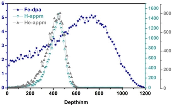
Figure 1.
Depth profiles of displacement damage and He and H concentration.
Microstructural analysis utilized a transmission electron microscope (TEM, FEI Company, Hillsboro, OR, USA) at 200 kV. Unirradiated TEM samples (3 mm in diameter) were prepared by mechanically thinning to ~50 μm, followed by final perforation using a twin-jet electropolisher (Struers ApS, Ballerup, Denmark) with a solution of HClO4-C2H5OH (1:19 vol.). In contrast, irradiated ones were fabricated using a dual-beam FIB system at Beijing University of Technology. The voltage of the ion gun is 0.5~30 kV, and the ion source is Ga ions. The sample cutting process uses a voltage of 30 kV, and the later cleaning work uses a voltage of 1 kV to reduce the FIB damage. The thickness of TEM analysis areas in this study is around 80 nm determined by the thickness fringe method. Dislocation loops and He bubbles were statistically analyzed from five regions per sample, counting ~200 loops and ~250 bubbles. Error bars indicate standard errors. The observation area was selected at a scale of 400 nm, that is to say, the peak of H and He concentration. On the one hand, this enables the most accurate reflection of the H-He synergistic effects. On the other hand, this can avoid the effect of the sample surface on the results [27] and exclude the influence of injected interstitials.
Nanoindentation (NI) tests employed a Nano indenter XP (Agilent Technologies, Santa Clara, CA, USA) equipped with a triangular cone for Berkovich indenter in continuous stiffness mode (2 nm harmonic displacement, 45 Hz, 50 nN, 0.05 nm/s strain rate) at RT. Eight indentations per sample, up to 2000 nm depth, ensured data reliability. An electron backscatter diffraction (EBSD) study was conducted, and the data were collected by Aztec Crystal software 2.12.
3. Results
3.1. Pre-Irradiation Microstructure
Figure 2a presents a typical low-magnification morphology of CLF-1 steel. Fine MX particles in the matrix and M23C6 phases at the grain boundaries (GBs) can be observed. The martensitic laths and high-density dislocations are also present. The corresponding EDS spectra of the matrix, Ta-rich MX phase, and Cr-rich M23C6 phase are given in Figure 2b–d, respectively.
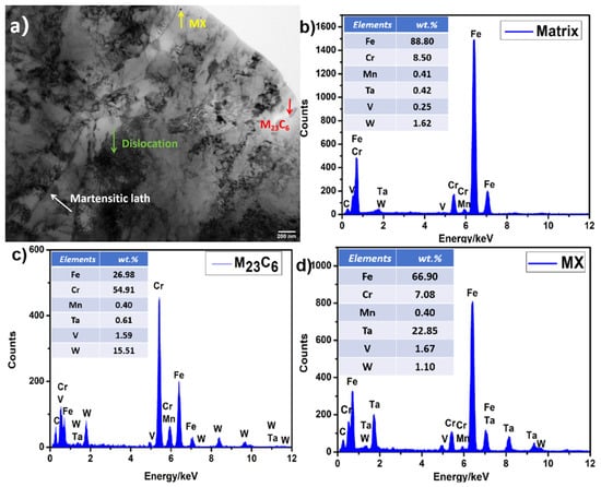
Figure 2.
(a) Bright-field (BF) TEM image of CLF-1 steel. (b) EDS image of the matrix. (c) EDS image of the M23C6 phase. (d) EDS image of the MX phase.
Based on the XRD patterns (Figure 3), the dislocation density is evaluated by the Williamson–Hall expressions [28]:
where is the micro-strain, which can be obtained by Equation (2):
where is the diffraction (Bragg) angle, is the full width at half maximum, and b is the Burger vector (≈0.26 nm) [12].
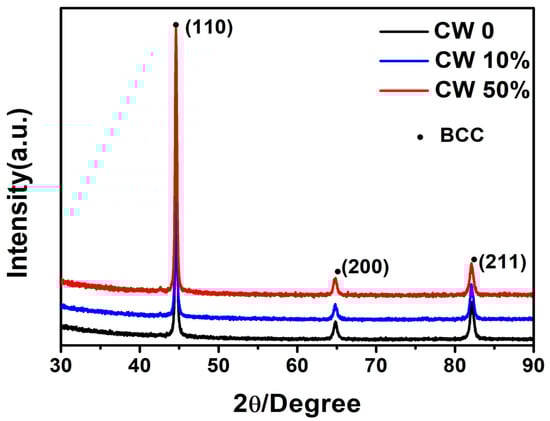
Figure 3.
The XRD pattern of cold-worked CLF-1 steels.
The specific values of the three samples are given in Table 2, which indicates that the dislocation density increases with increasing cold work amount.
Table 2.
The pre-irradiation dislocation density for the cold-worked CLF-1 steels.
3.2. Irradiation Hardening
NI profiles (Figure 4) showed a decrease in hardness, with depth beyond ~50 nm due to the indentation size effect. The average NI hardness of CW 0% is greatly increased after irradiation, while there is no significant difference between unirradiated and irradiated samples of CW 10% and CW 50%.
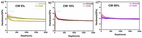
Figure 4.
Indentation-depth dependence of NI samples for (a) CW 0%, (b) CW 10%, and (c) CW 50%, respectively.
The Nix–Gao model was used to estimate the hardness of the samples and the relationship between NI hardness and indentation depth is described as the following Equation (3) [29]:
where is the hardness for a given indentation depth , is the hardness at the infinite depth that can be considered to the bulk hardness, and is a characteristic length that relies on the material and the shape of the indenter tip. Figure 5a–c show the plots of − of all samples.
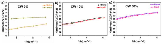
Figure 5.
H2 plotted against 1/h for the averaged NI hardness of (a) CW 0%, (b) CW 10%, and (c) CW 50%, respectively.
Based on the model, the nominal hardness of all samples can be obtained. The results are given in Table 3. The hardness increased by ~1.22 GPa, and the irradiation hardening rate reached ~38% for CW 0%, while there is no distinct difference in hardness between the irradiated and unirradiated samples in the deformed specimens (Figure 4), suggesting that cold working can improve the irradiation tolerance by introducing defect sinks.
Table 3.
NI hardness calculated using the Nix–Gao model for samples before and after irradiation.
Additionally, considering the negative hardening rate of CW 10% (−2.00% in Table 3), NI tests on the back side of three irradiated samples were conducted to evaluate the temperature effect under different deformations. Since the implanted depth was only 1200 nm, the backs of the samples were only affected by temperature and are denoted as Backirra-CW 0%, Backirra-CW 10%, and Backirra-CW 50%, respectively. Figure 6 exhibits averaged NI hardness profiles, with the depth for the backs of three irradiated samples. Compared with the irradiated side Hirra, the back-side hardness Hback of the two deformed samples decreased (listed in Table 3 using the same fitting method), indicating the defect recovery during 723 K. The larger the deformation, the greater the decrease.
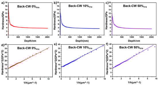
Figure 6.
Indentation-depth dependence of NI samples for (a) Backirra-CW 0%, (b) Backirra-CW 10%, and (c) Backirra-CW 50%, respectively. H2 plotted against 1/h for the averaged NI hardness of (d) Backirra-CW 0%, (e) Backirra-CW 10%, and (f) Backirra-CW 50%, respectively.
3.3. Grain Evolution After Irradiation
It is worth noting that the difference in the irradiation hardening between CW 10% and CW 50% is very small, although a much larger deformation, that is, sink density, was introduced to CW 50%. EBSD results revealed the grain morphology and size evolution subjected to cold working. Figure 7a–f show the inverse pole figures (IPF) of the unirradiated and irradiated samples, and Figure 7g–l give the related distribution of grain size. For CW 0%, both grain morphology and grain size remain almost unchanged after irradiation (Figure 7a,b,g,h). Some grains elongate in CW 10%, but no significant difference in grain size was found between Irra-CW 10% and Unirra-CW 10% (Figure 7c,d,i,j). However, the grain morphology has changed greatly in Unirra-CW50%, and the grains exhibit severe fragmentation, resulting in a ~20% reduction in the average grain size (Figure 7e,k), while for Irra-CW 50%, quite a few much finer equiaxed grains appeared, as denoted by black rectangles in Figure 7f, and the average grain size decreased by ~41% compared to Unirra-CW 50% (Figure 7l). We speculate that it is the triple factors of large cold-working deformation, 723 K, and relatively long-time multi-beam irradiation (4.8 h based on the dose rate of 1.09 dpa/h for Fe) that promote the occurrence of partial recrystallization in Irra-CW 50%, giving rise to the recovery of defects and a decrease in sink density. As a result, no significant difference was observed in irradiation hardening between CW 10% and CW 50%.
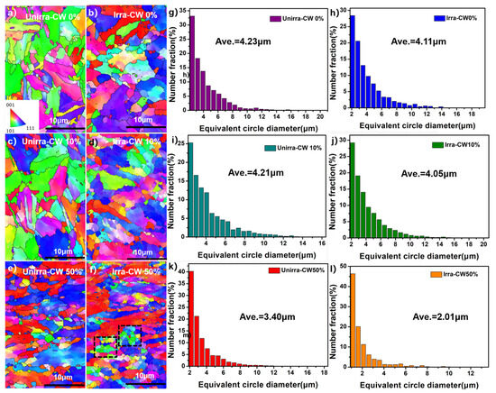
Figure 7.
The EBSD IPF maps and grain size distribution of CW 0%, CW 10%, and CW 50% before and after irradiation.
3.4. Microstructure Evolution After Irradiation
Figure 8 exhibited TEM images of He bubbles under- and over-focus for CW 0%, CW 10%, and CW 50%, respectively. The statistical results of bubble size are shown in Figure 9. The value of focus is about ±1 μm as described in reference [27] to determine the He bubbles. He bubbles tend to locate near dislocations and sub-grain boundaries. The number density of He bubbles experienced an initial increase followed by a decrease with the increase in the cold deformation, which was (2.10 ± 0.31) × 1022/m3, (2.40 ± 0.50) × 1022/m3, and (1.81 ± 0.29) × 1022/m3 for CW 0%, CW 10%, and CW 50%, respectively. In contrast, the mean size of He bubbles exhibited an opposite trend to the number density.
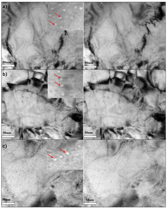
Figure 8.
TEM under- and over-focus images of He bubbles for the irradiated samples. (a) CW 0%, (b) CW 10%, and (c) CW 50%.
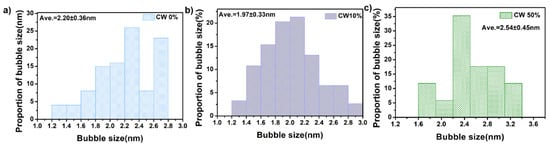
Figure 9.
The mean size of He bubbles for irradiated samples. (a) CW 0%, (b) CW 10%, and (c) CW 50%.
Figure 10 exhibits the typical TEM images of dislocation loops induced by irradiation. The observation of dislocation loops was conducted in the TEM BF image near the [111] zone axis. The representative dislocation loops were marked by red arrows. The similar two-beam condition with g vector of g = −110 was adopted to maintain the same imaging status at diffraction contrast. It is clearly found that the dislocation lines were decorated by dislocation loops [16,30,31]. Figure 11 presents the statistical results of loop size. The number density and mean size of dislocation loops are listed in Table 4. The trend in the dislocation loop number density and mean size was consistent with that of the He bubbles.
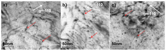
Figure 10.
TEM images of dislocation loops for varying samples. (a) CW 0%, (b) CW 10%, and (c) CW 50%.
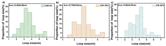
Figure 11.
The mean size of dislocation loops for varying samples. (a) CW 0%, (b) CW 10%, and (c) CW 50%.
Table 4.
The measured number density and average diameter of dislocation loops in irradiated samples.
4. Discussion
Non-Linear Effects of Cold Work on Defect Evolution and Irradiation Hardening
The non-linear evolution of irradiation defects in CLF-1 steels (dislocation loops/He bubbles: CW 50% < CW 0% < CW 10% in number density and CW 50% > CW 0% > CW 10% in mean size), as shown in Figure 12, stems from competing mechanisms between defect sinks and partial recrystallization at 723 K: (1) Pre-existing dislocations as defect sinks at CW 10%: Sink strength for dislocations can be estimated by Equation (4) [18]:
where (≈1.2) is the dislocation capture efficiency of order unity [20], and is the density of dislocations.
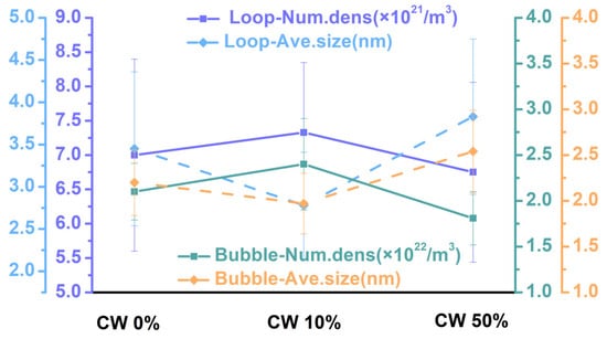
Figure 12.
The non-linear evolution of dislocation loops/He bubbles.
Moderate cold work introduces dense dislocations, enhancing sink strength to trap point defects and He atoms, promoting high-density nanoscale defects while suppressing coarsening [16,22]. (2) Dislocation annihilation induced by recrystallization at CW 50%: The combined effects of severe cold work and multi-beam irradiations at 723 K triggers partial recrystallization during irradiation. The recrystallized volume fraction () follows the Avrami equation, Equation (5) [32]:
where k is the Avrami constant, t is the irradiation time, n is the time exponent, and the value of n ranges from 1 to 2, 2 to 3, or 3 to 4 for one-, two-, or three-dimensional growth of the recrystallized grains, respectively [33].
The annihilation of dislocations (Δ∝) diminishes , enabling defect coalescence via enhanced diffusion, lowering number density but increasing sizes. (3) Thermal-diffusion competition: At 723 K, the diffusion coefficients of defects are thermally activated, which can be described by Equation (6):
where is pre-exponential factor, is the activation energy for diffusion, is Boltzmann constant, and is the absolute temperature.
The diffusion of point defects and He atoms are thermally enhanced [34]. In CW 10%, dislocations restrict the diffusion, stabilizing small bubbles/loops. In CW 50%, partial recrystallized zones enable long-range migration and coalescence of irradiation defects.
The non-linear relationship between irradiation hardening and cold work stems from the interplay of defect sink efficiency and microstructural evolution. Moderate cold work (10%) enhances sink strength via dense dislocation, effectively suppressing defect accumulation and hardening, whereas excessive cold work (50%) triggers partial recrystallization and stress relaxation under relatively long-time multi-beam irradiation, reducing dislocation density and enabling defects coalescence, which leads to the comparable hardening with CW 10%. For CW 0%, the absence of pre-deformation allows unmitigated irradiation defects accumulation, impeding the motion of dislocations, thus leading to significant hardening. Figure 13 summarizes the microstructural evolution and irradiation hardening mechanisms of the three samples.
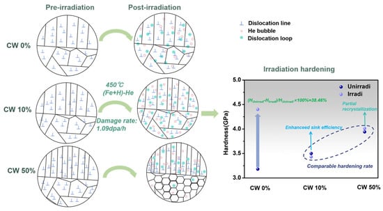
Figure 13.
Schematic diagrams of microstructural evolution and irradiation hardening mechanisms for three samples.
It is widely recognized that dislocation loops and He bubbles serve as obstacles to gliding dislocations in the slip plane and hinder their movements, thus leading to irradiation hardening [35]. The Dispersed Barrier Hardening (DBH) model (Equation (7)) is suitable for strong barriers, such as dislocation loops. And the FKH (Friedel–Kroupa–Hirsch) model (Equation (8)) was developed for weak barriers, such as He bubbles [36,37]. Here, the contributions of dislocation loops and He bubbles to irradiation hardening are evaluated by the two models, respectively.
where M is the averaged Taylor factor (≈3.0), and is the barrier strength, which is taken as 0.45 in BCC materials [12]. μ is shear modulus of matrix (≈84 GPa). b is the Burger vector (≈0.26 nm), N is the number density of the barrier, and d is the barrier size. is the yield stress increment, and stands for the hardening increase.
The contribution from dislocation loops induced by irradiation to the increment in is calculated as 0.459 GPa, 0.399 GPa, and 0.426 GPa for CW 0%, CW 10%, and CW 50%, respectively, while the contributions from He bubbles are 0.0372 GPa, 0.0447 GPa, and 0.0429 GPa. Thus, the total irradiation hardness increment is 0.462 GPa, 0.402 GPa, and 0.429 GPa for CW 0%, CW 10%, and CW 50%, respectively, based on Equation (9). Obviously, dislocation loops play a more important role in irradiation hardening compared to He bubbles. It should be emphasized that it is not easy to obtain the exact calculated hardness increment owing to the complexities of the experimental conditions. Errors are introduced both during the two-beam TEM analysis of dislocation loops and when the contrast of tiny He bubbles is covered by high-density defects, leading to significant statistical uncertainties [12].
Note that the DBH and FKH models, which quantify hardening from irradiation-induced defects alone, cannot fully explain the negligible hardening observed in the CW 10% and CW 50% samples, as the two models predict a relatively significant hardening effect.
The key to resolving this discrepancy lies in acknowledging the competing effect of irradiation-induced microstructural evolution, which encompasses stress relaxation, defect recovery, and partial recrystallization. For all cold-worked samples, the thermal and irradiation-enhanced diffusion at 723 K facilitates dislocation rearrangement and annihilation, leading to a softening that counteracts the hardening from new defect clusters. This stress relaxation effect occurs in both the CW 10% and CW 50% samples. However, in the CW 50% sample, this recovery is drastically accelerated into partial recrystallization, as directly evidenced by the EBSD results (Figure 7f,l), which create new, strain-free grains and drastically reduces the initial dislocation density.
Therefore, the final hardening is a balance: ΔH = (Hardening from defects) − (Softening from recovery/partial recrystallization). In the CW 10% and CW 50% samples, this competition results in the two opposing factors largely canceling each other out.
In summary, the design principle is not merely about increasing sink density but about optimizing it to ensure both high initial sink strength and microstructural stability under specific service conditions, such as temperature and dose. Moreover, systematically mapping this parameter space is a critical and logical next step. We plan to conduct a follow-up study investigating a finer series of cold work levels to precisely determine the optimal deformation window. Additionally, this study represents an initial step toward understanding the potential of cold work as a viable microstructural design strategy for enhancing irradiation tolerance. Subsequent studies will extend this investigation to prolonged irradiation durations and elucidate the synergistic contributions of precipitation, grain boundary segregation, and dislocation evolution to irradiation hardening. This work will provide essential scientific data for establishing quantitative microstructure design guidelines to maximize the radiation tolerance of RAFM steels.
5. Conclusions
In the present work, sequential (Fe2+ + H+)-He+ ions irradiations at 723 K were conducted to cold-worked CLF-1 steels. The non-linear relationship between cold work and defect evolution as well as irradiation hardening in CLF-1 steels was investigated. Moderate cold work (10%) in CLF-1 steel improves radiation resistance by introducing dense dislocation networks that suppress defect coarsening, achieving the highest defect density and smallest size. Excessive cold work (50%) triggers partial recrystallization under relatively long-time multi-beam irradiation, reducing sink density and enabling defect coalescence, which compromises radiation tolerance. Collectively, the amount of cold work (i.e., sink density) does not always correlate linearly with the improvement in irradiation hardening resistance, as this relationship is closely tied to the irradiation conditions. These findings highlight that a moderate level of cold-working deformation contributes to enhancing the sink strength, thus providing a viable approach for designing radiation-tolerant RAFM steels.
Note that this study represents an initial step toward understanding the potential of cold work as a microstructural design strategy for improving irradiation tolerance. Future work will explore longer irradiation durations and the synergistic effects of multiple mechanisms of irradiation hardening, including precipitation, grain boundary segregation, and dislocations evolution.
Author Contributions
Conceptualization, Z.X. and Q.Z.; methodology, Z.X., Q.Z., S.D. and H.L. (Hongtai Luo); software, S.D., H.L. (Hongtai Luo), F.Z., S.X., Y.C. and Y.W.; validation, Q.Z., Y.Z., L.G., H.L. (Hongbin Liao), G.Y. and C.W.; formal analysis, H.L. (Hongtai Luo), H.L. (Hongbin Liao) and G.Y.; investigation, Z.X., Q.Z., S.D., F.Z. and S.X.; resources, L.G., C.W., Y.C., Y.W., H.L. (Hongbin Liao) and G.Y.; data curation, S.D., H.L. (Hongtai Luo), F.Z., S.X., Y.C., Y.W., H.L. (Hongbin Liao) and G.Y.; writing—original draft preparation, Z.X.; writing—review and editing, Q.Z. and Y.Z.; visualization, Z.X., F.Z., S.X., Y.C. and Y.W.; supervision, Q.Z., Y.Z., L.G. and C.W.; project administration, Q.Z., L.G. and C.W.; funding acquisition, Q.Z. All authors have read and agreed to the published version of the manuscript.
Funding
This work is supported by the National MCF Energy R&D Program (Grant No. 2022YFE03110000), the National Natural Science Foundation of China (Grant No. 51971030), and the State Key Laboratory of Nuclear Physics and Technology, Peking University under Grant Nos. NPT2023KFJ26 and NPT2021KFJ24.
Data Availability Statement
The original contributions presented in this study are included in the article. Further inquiries can be directed to the corresponding author.
Conflicts of Interest
The authors declare no conflict of interest.
References
- Yvon, P.; Carré, F. Structural materials challenges for advanced reactor systems. J. Nucl. Mater. 2009, 385, 217–222. [Google Scholar] [CrossRef]
- Zinkle, S.J.; Busby, J.T. Structural materials for fission & fusion energy. Mater. Today 2009, 12, 12–19. [Google Scholar] [CrossRef]
- Cheng, Z.; Sun, J.; Cui, J.; Chen, D.; Ren, J.; Wang, T.; Chang, H.; Tai, P.; Zhang, L.; Tian, Y.; et al. Microstructural evolution, strengthening and high thermal conductivity mechanisms of FeCrV-based medium-entropy alloys with Laves phase precipitation formed by adding minimal Ti. Mater. Charact. 2023, 200, 112860. [Google Scholar] [CrossRef]
- Baluc, N. Materials for fusion power reactors. Plasma Phys. Control. Fusion 2006, 48, B165–B177. [Google Scholar] [CrossRef]
- Knaster, J.; Moeslang, A.; Muroga, T. Materials research for fusion. Nat. Phys. 2016, 12, 424–434. [Google Scholar] [CrossRef]
- Trinkaus, H.; Singh, B. Helium accumulation in metals during irradiation—Where do we stand? J. Nucl. Mater. 2003, 323, 229–242. [Google Scholar] [CrossRef]
- Molvik, A.; Ivanov, A.; Kulcinski, G.L.; Ryutov, D.; Santarius, J.; Simonen, T.; Wirth, B.D.; Ying, A. A Gas Dynamic Trap Neutron Source for Fusion Material and Subcomponent Testing. Fusion Sci. Technol. 2010, 57, 369–394. [Google Scholar] [CrossRef]
- Clowers, L.N.; Was, G.S. The effect of hydrogen co-injection on the microstructure of triple ion irradiated F82H. J. Nucl. Mater. 2024, 601, 155331. [Google Scholar] [CrossRef]
- Yin, Z.; Guo, L.; Chen, Y.; Xie, Z.; Lin, W.; Cao, J.; Long, Y.; Luo, H.; Yan, R. Effect of irradiation with varying H/He ratio on defect clusters and hardening in CLAM steel. J. Alloys Compd. 2025, 1016, 178935. [Google Scholar] [CrossRef]
- Ding, Z.; Zhang, C.; Yang, Y.; Chen, Y.; Zhang, X.; Song, Y.; Ma, T.; Xu, Y.; Luo, G. Vickers hardness change of the Chinese low-activation ferritic/martensitic steel CLF-1 irradiated with high-energy heavy ions. Plasma Sci. Technol. 2020, 22, 055601. [Google Scholar] [CrossRef]
- Yuan, D.Q.; Ma, H.L.; Fan, P.; Zheng, Y.N.; Zuo, Y.; Zhang, Q.L.; Wen, A.; Feng, W.; Liang, J.C.; Xiong, W.J.; et al. Synergistic Effect on Formation of Radiation Damage in CLAM Steel Studied by Triple Beam Irradiation. Defect Diffus. Forum 2017, 373, 117–121. [Google Scholar] [CrossRef]
- Wei, Y.; Liu, P.; Zhu, Y.; Wang, Z.; Wan, F.; Zhan, Q. Evaluation of irradiation hardening and microstructure evolution under the synergistic interaction of He and subsequent Fe ions irradiation in CLAM steel. J. Alloys Compd. 2016, 676, 481–488. [Google Scholar] [CrossRef]
- Zimber, N.; Vladimirov, P.; Klimenkov, M.; Jäntsch, U.; Vila, R.; Chakin, V.; Mota, F. Microstructural evolution of three potential fusion candidate steels under ion-irradiation. J. Nucl. Mater. 2020, 535, 152160. [Google Scholar] [CrossRef]
- Wakai, E.; Kikuchi, K.; Yamamoto, S.; Aruga, T.; Ando, M.; Tanigawa, H.; Taguchi, T.; Sawai, T.; Oka, K.; Ohnuki, S. Swelling behavior of F82H steel irradiated by triple/dual ion beams. J. Nucl. Mater. 2003, 318, 267–273. [Google Scholar] [CrossRef]
- Ding, J.; Yang, S.; Zhu, B.; Li, Q.; Long, Y.; Wan, F. Influence of high-temperature ion irradiation on microstructures of the deformed and heat-treated V-4Cr-4Ti alloy. Fusion Eng. Des. 2017, 125, 407–414. [Google Scholar] [CrossRef]
- Han, X.; Niu, M.; Yang, Y.; Li, Z.; Wang, T.; Zhang, C. Investigation of irradiation defects and hardening of cold-worked vanadium alloys. Fusion Eng. Des. 2023, 189, 113490. [Google Scholar] [CrossRef]
- Bai, X.-M.; Voter, A.F.; Hoagland, R.G.; Nastasi, M.; Uberuaga, B.P. Efficient Annealing of Radiation Damage Near Grain Boundaries via Interstitial Emission. Science 2010, 327, 1631–1634. [Google Scholar] [CrossRef]
- Zinkle, S.; Snead, L. Designing Radiation Resistance in Materials for Fusion Energy. Annu. Rev. Mater. Res. 2014, 44, 241–267. [Google Scholar] [CrossRef]
- Zinkle, S.; Boutard, J.; Hoelzer, D.; Kimura, A.; Lindau, R.; Odette, G.; Rieth, M.; Tan, L.; Tanigawa, H. Development of next generation tempered and ODS reduced activation ferritic/martensitic steels for fusion energy applications. Nucl. Fusion 2017, 57, 092005. [Google Scholar] [CrossRef]
- Duan, B.; Heintze, C.; Bergner, F.; Ulbricht, A.; Akhmadaliev, S.; Oñorbe, E.; de Carlan, Y.; Wang, T. The effect of the initial microstructure in terms of sink strength on the ion-irradiation-induced hardening of ODS alloys studied by nanoindentation. J. Nucl. Mater. 2017, 495, 118–127. [Google Scholar] [CrossRef]
- Ukai, S.; Uwaba, T. Swelling rate versus swelling correlation in 20% cold-worked 316 stainless steels. J. Nucl. Mater. 2003, 317, 93–101. [Google Scholar] [CrossRef]
- Han, X.; Niu, M.; Yang, Y.; Zhang, C.; Meng, X.; Li, Z.; Wang, T. Effect of cold work deformationon irradiation hardening of vanadium alloys. Nucl. Fusion 2022, 62, 126010. [Google Scholar] [CrossRef]
- Li, B.; Wang, Z.; Wei, K.; Shen, T.; Yao, C.; Zhang, H.; Sheng, Y.; Lu, X.; Xiong, A.; Han, W. Evaluation of helium effect on irradiation hardening in F82H, ODS, SIMP and T91 steels by nano-indentation method. Fusion Eng. Des. 2019, 142, 6–12. [Google Scholar] [CrossRef]
- Fu, H.; Li, B.; Xu, S.; Zhu, H.; Han, S.; Luo, R.; Liao, H.; Wang, X.; Chen, J.; Li, P. Effect of irradiation temperature on radiation hardening of CLF-1 steel. Fusion Eng. Des. 2023, 189, 113488. [Google Scholar] [CrossRef]
- Liao, H.; Wang, X.; Yang, G.; Feng, Y.; Wang, P.; Feng, K. Recent progress of R&D activities on reduced activation ferritic/martensitic steel (CLF-1). Fusion Eng. Des. 2019, 147, 111235. [Google Scholar] [CrossRef]
- ASTM E521–89; Standard Practice for Neutron Radiation Damage Simulation by Charged-Particle Irradiation. ASTM International: West Conshohocken, PA, USA, 2009.
- Yao, B.; Edwards, D.J.; Kurtz, R.J.; Odette, G.R.; Yamamoto, T. Multislice simulation of transmission electron microscopy imaging of helium bubbles in Fe. J. Electron Microsc. 2012, 61, 393–400. [Google Scholar] [CrossRef] [PubMed]
- Chen, Z.; Han, W.; Yu, J.; Kecskes, L.; Zhu, K.; Wei, Q. Microstructure and helium irradiation performance of high purity tungsten processed by cold rolling. J. Nucl. Mater. 2016, 479, 418–425. [Google Scholar] [CrossRef]
- Nix, W.D.; Gao, H. Indentation size effects in crystalline materials: A law for strain gradient plasticity. J. Mech. Phys. Solids 1998, 46, 411–425. [Google Scholar] [CrossRef]
- Abromeit, C. Aspects of simulation of neutron damage by ion irradiation. J. Nucl. Mater. 1994, 216, 78–96. [Google Scholar] [CrossRef]
- Hull, D.; Bacon, D.J. Introduction to Dislocations; Elsevier: Amsterdam, The Netherlands, 2011. [Google Scholar]
- Shirzad, K.; Viney, C. A critical review on applications of the Avrami equation beyond materials science. J. R. Soc. Interface 2023, 20, 20230242. [Google Scholar] [CrossRef]
- Matsui, T.; Ogawa, T.; Adachi, Y. Relationship between three-dimensional microstructure and Avrami exponent for recrystallization in pure iron. Results Mater. 2019, 1, 100002. [Google Scholar] [CrossRef]
- Zinkle, S. 1.03-Radiation-Induced effects on microstructure. Compr. Nucl. Mater. 2012, 1, 65–98. [Google Scholar]
- Was, G.S. Fundamentals of Radiation Materials Science: Metals and Alloys; Springer: Berlin/Heidelberg, Germany, 2007. [Google Scholar]
- Friedel, J. Vacancies and Interstitial Atoms. In Dislocations; Pergamon Press: Oxford, UK, 1964; pp. 76–103. [Google Scholar]
- Kroupa, F.; Hirsch, P.B. Elastic interaction between prismatic dislocation loops and straight dislocations. Discuss. Faraday Soc. 1964, 38, 49–55. [Google Scholar] [CrossRef]
Disclaimer/Publisher’s Note: The statements, opinions and data contained in all publications are solely those of the individual author(s) and contributor(s) and not of MDPI and/or the editor(s). MDPI and/or the editor(s) disclaim responsibility for any injury to people or property resulting from any ideas, methods, instructions or products referred to in the content. |
© 2025 by the authors. Licensee MDPI, Basel, Switzerland. This article is an open access article distributed under the terms and conditions of the Creative Commons Attribution (CC BY) license (https://creativecommons.org/licenses/by/4.0/).