Article

The Impact of Ce on the Microstructure and Properties of Weld Metal in Corrosion-Resistant Steel

1
Jiangsu Fuermu Welding Corporation, Wuxi 214442, China
2
State Key Laboratory of Metastable Materials Science and Technology, Yanshan University, Qinhuangdao 066004, China
3
Hebei Key Lab for Optimizing Metal Product Technology and Performance, Yanshan University, Qinhuangdao 066004, China
*
Author to whom correspondence should be addressed.
Metals 2025, 15(12), 1289; https://doi.org/10.3390/met15121289
Submission received: 21 October 2025 / Revised: 22 November 2025 / Accepted: 23 November 2025 / Published: 25 November 2025

Abstract

In this study, two types of submerged arc welding (SAW) wires were prepared—one without cerium (Ce) and another containing 0.14 wt.% Ce. Deposition experiments were carried out on corrosion-resistant crude oil storage tank steel plates using a multi-layer, multi-pass welding process. Through a combination of microstructural characterization techniques, including optical microscopy (OM), scanning electron microscopy (SEM), energy-dispersive spectroscopy (EDS), electron backscatter diffraction (EBSD), and transmission electron microscopy (TEM), along with mechanical property testing, a systematic investigation was conducted to evaluate the influence of Ce on the weld metal microstructure and its impact toughness at −20 °C. The results reveal that Ce introduced via the welding wire into the weld seam refines and disperses inclusions, leading to the formation of composite inclusions primarily composed of Ce2O3, Ce2O2S, and CeS. These Ce-enriched inclusions serve as heterogeneous nucleation sites, increasing the area fraction of acicular ferrite (AF) within the weld columnar grain region from 52% to 83%, and within the heat-affected zone from 20% to 37%. Correspondingly, the proportions of blocky and polygonal ferrite decrease, while the size of martensite/austenite (M/A) constituents is reduced. The addition of Ce thus diminishes the size of hard phase inclusions and M/A constituents in the weld metal, enhancing the critical fracture stress and increasing the energy required for crack initiation. Meanwhile, the higher proportion of AF elevates the density of high-angle grain boundaries, thereby improving crack propagation resistance. These combined effects raise the −20 °C impact energy of the weld metal from 117 J to 197 J.

1. Introduction

With the sustained growth of both the national economy and national defense construction, petroleum—serving as a vital strategic resource and a fundamental energy source—has experienced a steady increase in consumption, accompanied by the progressive development of petroleum reserve facilities. As the core infrastructure of strategic petroleum reserves, large crude oil storage tanks play a crucial role in ensuring national energy security, making their safety and durability of paramount importance [1,2]. However, the bottom plates of these tanks are continuously exposed to sedimentary water containing corrosive agents such as chloride ions (Cl) and hydrogen sulfide (H2S), which makes them highly susceptible to corrosion. In particular, welded joints are prone to localized degradation due to compositional and microstructural heterogeneities, thereby posing a significant threat to the overall service life and operational reliability of the tanks. Furthermore, large-scale storage tanks demand stringent performance requirements for weld strength and low-temperature toughness under complex service conditions, including external loading, plate thickness design, and stability verification. Consequently, the development of welding materials that exhibit high strength, superior toughness, and excellent corrosion resistance has become a key technological focus for ensuring the long-term safety and reliability of crude oil storage tanks.
Significant progress has been achieved in the development of corrosion-resistant steels for crude oil storage tanks, with grades such as 12MnNiVR, 08MnNiVR, and SPV490 being widely applied in engineering practice. However, the research and development of high-performance corrosion-resistant welding consumables compatible with these steels have not kept pace. Commonly used submerged arc welding consumables, such as US-49 and CHW-S7, while capable of meeting basic mechanical property requirements, lack a systematic incorporation of corrosion-resistant alloying elements in their compositional design. Consequently, the welds produced with these consumables exhibit inadequate durability under corrosive service conditions. To improve weld corrosion resistance, alloying elements such as Si, Mo, Ni, and Cu are typically introduced. Nevertheless, the addition of these elements often promotes the formation of brittle hard phases, which severely compromise the weld’s low-temperature toughness [3,4,5]. Furthermore, an excessive alloying content in the welding wire can deteriorate weldability, leading to defects such as poor bead morphology, porosity, and cracking. These challenges significantly limit the practical application of high-performance corrosion-resistant welding consumables.
It has been reported [6,7] that the addition of Ce to welding wire can lead to the formation of fine, uniformly distributed non-metallic inclusions. These inclusions are well-matched with acicular ferrite (AF) in the weld metal and can serve as effective nucleation sites for AF. Consequently, the proportion of AF in the weld increases, leading to grain refinement and alterations in the distribution of high-angle and low-angle grain boundaries. Since crack initiation and propagation are closely related to the microstructural features—such as grain size, grain boundary characteristics, and phase composition—these microstructural modifications have a significant influence on the impact toughness of the weld.
However, some researchers have suggested that Ce tends to segregate at grain boundaries, thereby increasing lattice distortion and grain boundary energy, which promotes the preferential nucleation of eutectic ferrite. Simultaneously, Ce addition may enhance the hardenability of the matrix and increase the presence of brittle, hard phases. This can lead to the coarsening of inclusions and a reduction in available nucleation sites, ultimately resulting in a deterioration of the weld’s mechanical properties [8].
To investigate the toughening mechanism of Ce in welds, this study designed two types of welding wires—one containing Ce and one without Ce—and conducted melting experiments. Characterization techniques including optical microscopy (OM), scanning electron microscopy (SEM), energy-dispersive spectroscopy (EDS), and transmission electron microscopy (TEM) were employed to examine the effects of Ce-containing elements on the microstructural evolution of the weld metal and on the nucleation behavior induced by non-metallic inclusions. Furthermore, the fracture characteristics of the Ce-containing welds were analyzed to elucidate the influence of Ce on the weld’s toughening mechanism.

2. Materials and Methods

2.1. Welding Wire Manufacturing

Steels intended for welding wires, both without Ce and containing 0.14 wt.% Ce, were produced in a 75 kg vacuum induction furnace, with each composition processed in a separate furnace. The molten steels were subsequently cast into single ingots. Samples were collected from various locations within each ingot, and their chemical compositions were analyzed using direct-reading spectrometry and standard chemical analysis methods. The results of these analyses are presented in Table 1.
The preparation of welding wires was initiated by removing the ingot riser and polishing the ingot surface. The ingot was then heated to 1200 °C in a heat treatment furnace and held at this temperature for 2 h. Subsequently, the billet was opened and forged into a square cross-section of 50 mm × 50 mm with a length of approximately 1500 mm. The forged billet was polished, reheated to 1200 °C, and then subjected to rolling and drawing processes to produce coils with a diameter of 6.5 mm. Finally, the coils were further processed into 4 mm submerged arc welding wire through a series of operations including pickling, borax treatment, rough drawing, fine drawing, additional pickling, and copper plating.
The test material is corrosion-resistant crude oil storage tank steel in a thermomechanically controlled processed (TMCP) and tempered condition. The dimensions of the test plates are 200 mm × 500 mm × 21.5 mm, and their chemical composition is provided in Table 2. Metallographic analysis reveals that the steel microstructure predominantly consists of acicular ferrite (AF) and granular bainite (GB), contributing to its excellent combination of mechanical properties. The comprehensive mechanical properties of the base material are summarized in Table 1.
Considering the severe corrosion environment at the joints of corrosion-resistant crude-oil storage tanks, 0.4% silicon was added to the welding wire to ensure corrosion resistance. To ensure that the Si element is fully transferred from the welding wire to the weld metal and that the weld strength meets the standard, the fluoride–basic medium-silicon flux SJ105 is selected. The flux exhibits a basicity (BIIW) between 2.4 and 3.0 and a particle size ranging from 10 to 60 mesh. Table 3 presents the detailed composition of SJ105 flux. Prior to use, the flux was preheated in a drying oven at 300 °C for 1.5 h to remove moisture and optimize its performance.

2.2. Welding Process

Based on the prepared Ce-free and 14Ce welding wires, along with the selected base materials and fluxes, a welding wire melting test was conducted in accordance with the NB/T 47014-2011 standard, Welding procedure qualification for pressure equipment [9,10]. The welding parameters used are summarized in Table 4. To prevent an excessively large fusion ratio in the welded test panels—which could potentially affect the experimental results—the melting test was performed using a large-gap butt bevel, as illustrated in Figure 1a. The test panels were fabricated from the same parent material mentioned above, and welding was carried out using a KZ-1 automatic submerged arc welding machine (Tangking Electric Welding Machine Co., Ltd., Tangshan, China).

2.3. Experimental Procedure

Ultrasonic testing of the clad metal is performed 24 h after the completion of welding. Samples for chemical composition analysis and impact testing are taken from the qualified regions of the weld metal. Each sample is tested in triplicate, with the average value representing the chemical composition of the weld. Impact test specimens are uniformly extracted from the upper surface of the weld within 2 mm. The machining dimensions and testing methods for the welded joint specimens comply with GB/T 228.1-2021 “Metallic materials—Tensile testing—Part 1: Method of test at room temperature” [11] and GB/T 229-2020 “Metallic materials—Charpy pendulum impact test method” [12] The sampling plan is illustrated in Figure 1b. Impact testing is conducted using a ZBC2452-CE pendulum impact tester (Wuxi Deep Instrument Equipment Co., Ltd., Wuxi, China). Specimens measure 10 mm × 10 mm × 55 mm, with a V-notch oriented parallel to the weld thickness. Tests are carried out at −20 °C, achieved using a CDC-80 low-temperature impact testing chamber (Changzhou Tianjing Experiment Instrument Factory, Changzhou, China), with anhydrous ethanol as the cooling medium [13,14].
The microstructure of the weld was characterized and examined using an optical microscope (OM, ZEISS, Oberkochen, Germany). As shown in Figure 1c, vertical weld impact fracture notches were sampled using an EDM wire-cutting machine (TDK450C, Guangzhou Li Diao Electronic Equipment Co., Ltd., Guangzhou, China) and subsequently prepared into hot-mounted specimens. Coarse grinding was performed sequentially with 200#, 400#, 800#, 1000#, and 1500# grit sandpapers, followed by final fine grinding using 2000# sandpaper. The specimens were then mechanically polished, and the size, morphology, and distribution of inclusions were observed under the optical microscope.
For microstructural analysis, the specimens were etched with a 4% nitric acid-alcohol solution. The columnar grain regions and the heat-affected zone (HAZ) of the weld bead were examined under a metallographic microscope. For each weld group, ten representative fields of view were preserved from both the weld columnar grain zone and the HAZ. Image-Pro Plus 6.0 software was employed to quantify the proportions of acicular ferrite, blocky ferrite, and polygonal ferrite within the microstructure.
Subsequently, the specimens were re-polished and etched for 45 s using Leper’s reagent, consisting of a 1:1 mixture of 4% picric acid in alcohol and 1% sodium metabisulphite. The morphology, distribution, and size of the martensite/austenite (M/A) constituents were examined under a metallographic microscope, with ten fields of view preserved per weld group from both the columnar grain zone and the HAZ. Image-Pro Plus software was further employed to statistically analyze the area fraction and average diameter of the M/A components.
The microstructure of the weld metal specimens and their correlation with non-metallic inclusions were further investigated using a Hitachi S-4800 scanning electron microscope (Hitachi High-Tech, Tokyo, Japan). An X-ray energy-dispersive spectrometer (Xplore 30, Oxford Instruments plc, London, UK) was employed to conduct both point and area analyses of the non-metallic inclusions, allowing detailed characterization of their composition and elemental distribution within the weld.
To investigate the fracture mechanisms of the weld metal, scanning electron microscopy (SEM) was employed to analyze both the macroscopic morphology of the fracture surfaces and the microscopic features of the fibrous and radiating zones. Electron backscatter diffraction (EBSD) (EDAX, New York, NY, USA), integrated with the SEM, was used to examine the relationship between secondary crack propagation paths and the local microstructural orientation. Sample preparation involved sequential grinding and polishing, followed by electrochemical polishing using an electrolytic solution composed of 15% perchloric acid, 80% methanol, and 5% glycerol.
Transmission electron microscopy (TEM; JEOL, Tokyo, Japan) was employed to investigate the microstructural characteristics, dislocations, and distribution of non-metallic inclusions within the specimens. Selective area electron diffraction (SAED) was performed on the inclusions to determine their phase composition, while line scanning across the prior austenite grain boundaries (PAGB) was conducted to examine Ce element segregation. For sample preparation, 800 µm thick metal sections were initially extracted from the impact fracture surface using electrical discharge machining (EDM) and subsequently ground to a thickness of 30–40 µm with emery paper. The resulting metal sheets were then punched into circular specimens with a diameter of 3 mm. Final thinning of the specimens was achieved at room temperature using a dual-jet electrolytic polishing technique. The electrolyte consisted of a 7% perchloric acid–acetic acid solution, applied at a voltage of 18.5 V and maintained at 25 °C.

3. Results

3.1. Microstructural Characterization

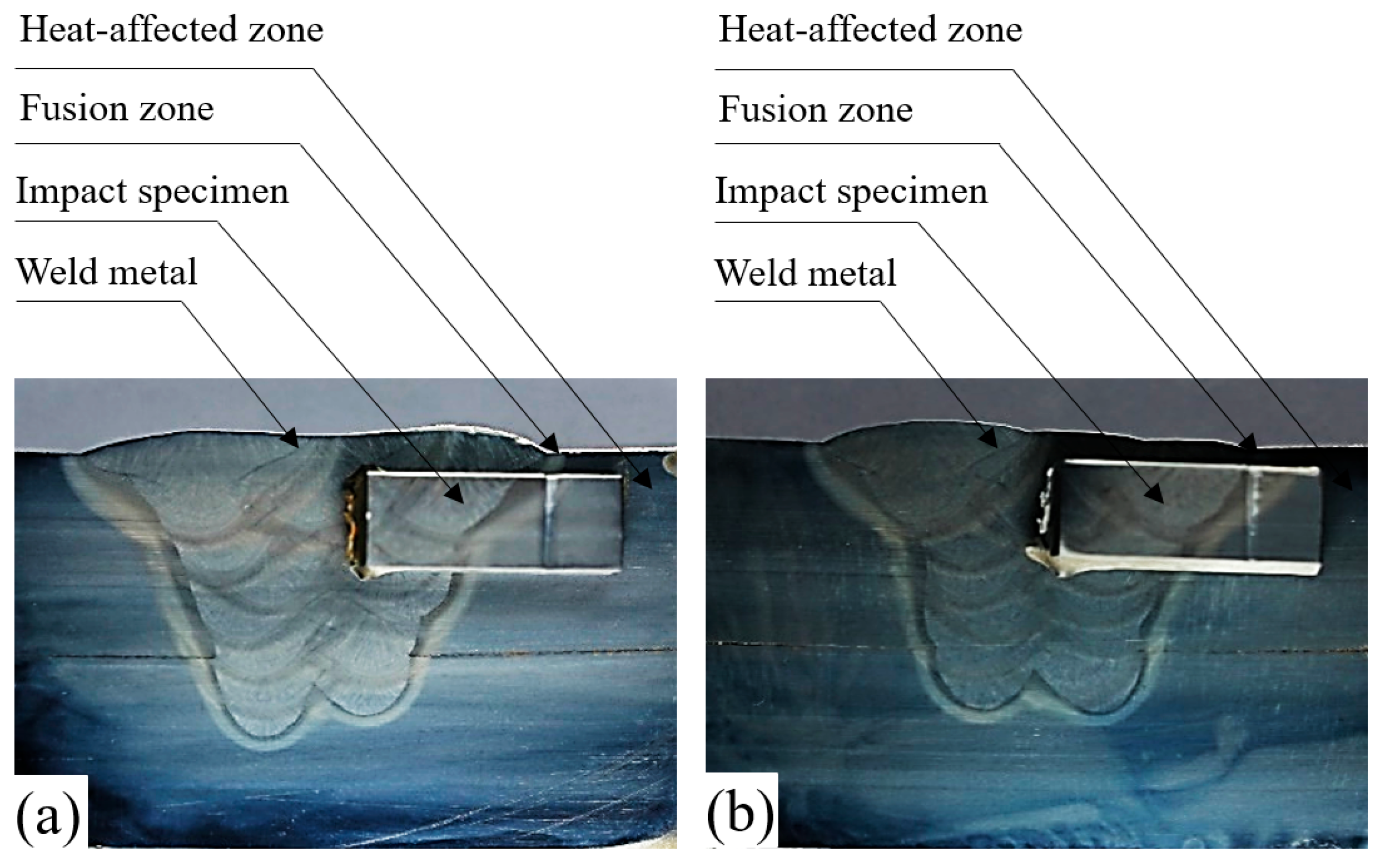
Figure 2a,b illustrates the macroscopic morphology of the deposited metal for Ce-free and 14Ce-containing welding wires, respectively. Owing to the multi-layer, multi-pass welding process employed, specimens for impact and tensile testing were extracted 2 mm below the weld surface. The impact specimens predominantly comprise two distinct regions: the columnar grain zone and the weld heat-affected zone [15]. Furthermore, the uniform weld bead height and consistent fusion width indicate a stable droplet transfer throughout the welding process.
The chemical composition analysis of the weld metal is presented in Table 5. No loss of Ni, Cu, or Mo was observed during welding, confirming that the base metal did not melt into the weld pool and interfere with the test results. This indicates that the deposition test design was appropriate. Elements such as C, Si, and Mn, which have a high affinity for oxygen, are oxidized to CO, SiO2, and MnO, respectively, during droplet transition in an oxygen-rich atmosphere. Based on the chemical composition of the deposited metal, the average transition coefficient for carbon was calculated to be 0.87. In contrast, the transition coefficients for silicon and manganese were 0.98 and 0.99, respectively, approaching unity and slightly elevated. This can be primarily attributed to the substantial quantities of SiO2 and MnO added to the flux, which are reduced by elemental iron in the molten state to release free silicon and manganese, thereby compensating for losses in the molten pool.
Furthermore, the addition of oxygen-affinitive elements such as Ce and Ti, which exhibit a stronger affinity for oxygen, promotes their preferential oxidation during droplet transition, thereby reducing the burn-off of Si and Mn. In welds, the oxides of Ce and Ti exist in multiple forms, predominantly as CeO2, Ce2O3, TiO, TiO2, and Ti2O3. Depending on the relative reactivity of Ce, Ti, and O, the reactions (1)–(8) may occur [16,17].
2 Ce + 3 O =   Ce 2 O 3
Ce 2 O 3 + O = 2 Ce O 2
2 Ti + 3 O =   Ti 2 O 3
Ti 2 O 3 + O = 2 Ti O 2
Non-metallic inclusions formed through oxidation during the droplet transition undergo nucleation, growth, and coalescence to form larger inclusions, with some rising to the surface of the slag. The slag, due to the addition of fluxing minerals, often contains trace amounts of sulfur, which increases the activity of sulfur within the slag. In its molten state the slag interacts with the weld pool, facilitating further desulfurization reactions, particularly involving elements such as Ce and Mn [18,19].
2 Ce + O + 2 S = Ce 2 S 2 O
Ce 2 O 3 + 2 S =   Ce 2 S 2 O + O 2
Ce + S = CeS
2 Ce + 3 S =   Ce 2 S 3
A portion of the oxidized inclusions of Ce, including sulphides and oxysulphides, is retained within the weld, while another portion rises to the surface and is expelled. Simultaneously, a small fraction of Ce may remain in solid solution within the weld metal. Consequently, the total Ce content in the weld is limited, resulting in a transition coefficient of Ce from the wire of only 0.03.
Figure 3a,c illustrates the metallographic structures of the columnar crystal regions of deposited metals with different Ce contents. The microstructures in these regions are composed of acicular ferrite (AF), quasi-polygonal ferrite (QPF), grain boundary ferrite (PF), and a small fraction of granular bainite (GB) or martensite/austenite (M/A). The morphology and relative proportion of each phase, however, differ significantly between the two Ce levels. The M/A constituent, consisting of untransformed austenite and martensite, plays a critical role in determining mechanical properties such as toughness and brittleness, with its amount, morphology, and distribution being particularly influential.
For the 0 wt% Ce deposited metal, the columnar crystal region is primarily dominated by PF and QPF. PF forms a reticulated, closed structure along the austenitic grains, while a small amount of AF nucleates and grows within the austenitic grains. In contrast, the deposited metal containing 0.005 wt% Ce is dominated by fine-grained AF with interlocking structures, accompanied by a small fraction of QPF. PF forms only sporadically near the prior austenite grain boundaries (PAGB). Quantitative analysis of the columnar crystal region indicates that the AF area fraction increases from 52% to 83% with the addition of Ce, whereas the fractions of PF and QPF decrease from 26% to 4% and 12% to 8%, respectively.
The heat-affected zone (HAZ) of the weld passes exhibits a microstructure distinct from that of the columnar crystal region due to the thermal cycling effect of subsequent passes. As shown in Figure 3b,d, the HAZ consists of QPF, AF, and GB. With 0.005 wt% Ce, the HAZ displays a higher fraction of AF and a more uniform equiaxed structure of QPF compared to the Ce-free metal. Overall, both AF and PF increase with the addition of Ce, rising from 20% to 37% and from 51% to 63%, respectively, as summarized in Table 6.
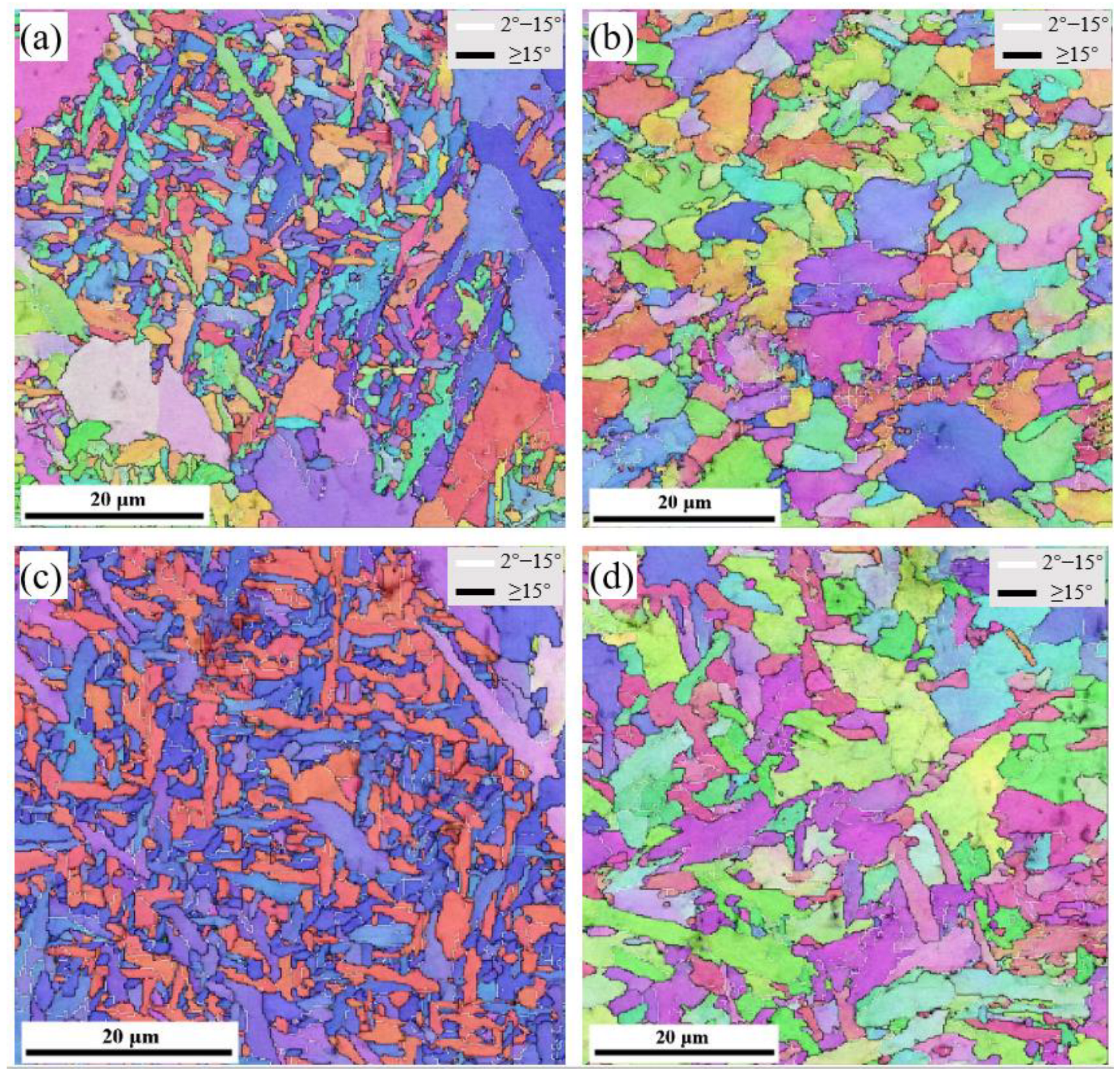
Electron backscatter diffraction (EBSD) characterization was employed to analyze microstructural features, including grain size and crystallographic orientation differences. Figure 4a–d presents the inverse pole figure (IPF) maps of the columnar crystalline zone and the heat-affected zone (HAZ) of the weld channel in Ce-free and 0.005 wt% Ce-containing deposited metals, respectively. In these maps, black lines indicate large-angle grain boundaries (LAGB) with a misorientation angle (MTA) greater than 15°, while white lines denote small-angle grain boundaries (SAGB) with orientation differences between 2° and 15°. Color variations represent the degree of grain orientation difference [13]. The fraction of LAGB in the columnar zone was 59.2% for the Ce-free metal and 80.1% for the 0.005 wt% Ce-containing metal. In the HAZ, the corresponding fractions were 32% and 46%. The mean equivalent diameters (MEDs) of grains in the columnar zone were 1.85 μm for the Ce-free metal and 1.05 μm for the Ce-containing metal, whereas in the HAZ, the MEDs were 2.65 μm and 2.12 μm, respectively.
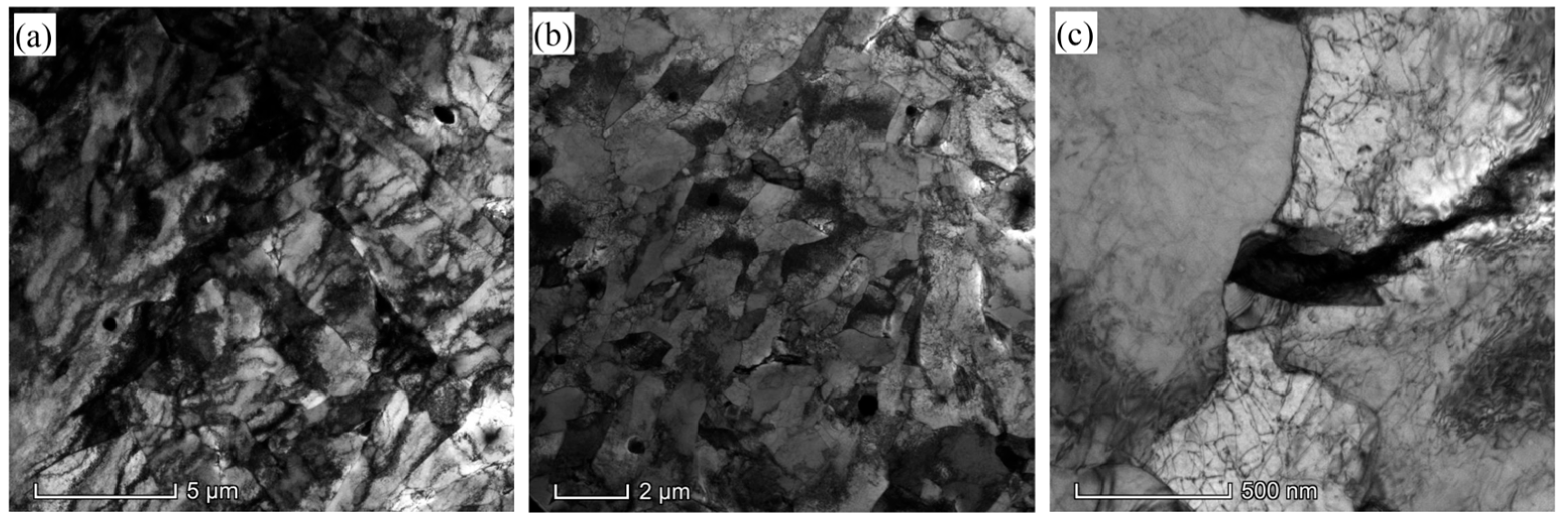
The micro-morphology of the 0.005 wt% Ce deposited metal in the columnar crystal region and the heat-affected zone (HAZ) of the weld channel, as observed under TEM, is shown in Figure 5a,b. In the columnar crystal region, acicular ferrite (AF) is observed to grow radially around the inclusions. In contrast, the microstructure of the HAZ is primarily dominated by quasi-polygonal ferrite (QPF). Compared with QPF, AF contains a higher density of internal dislocations, which are entangled to form a dislocation network. Figure 5c presents a high-magnification view of the martensite/austenite (M/A) constituent, revealing that it preferentially grows in the adjacent ferrite gaps and possesses a significant number of internal dislocations [20].
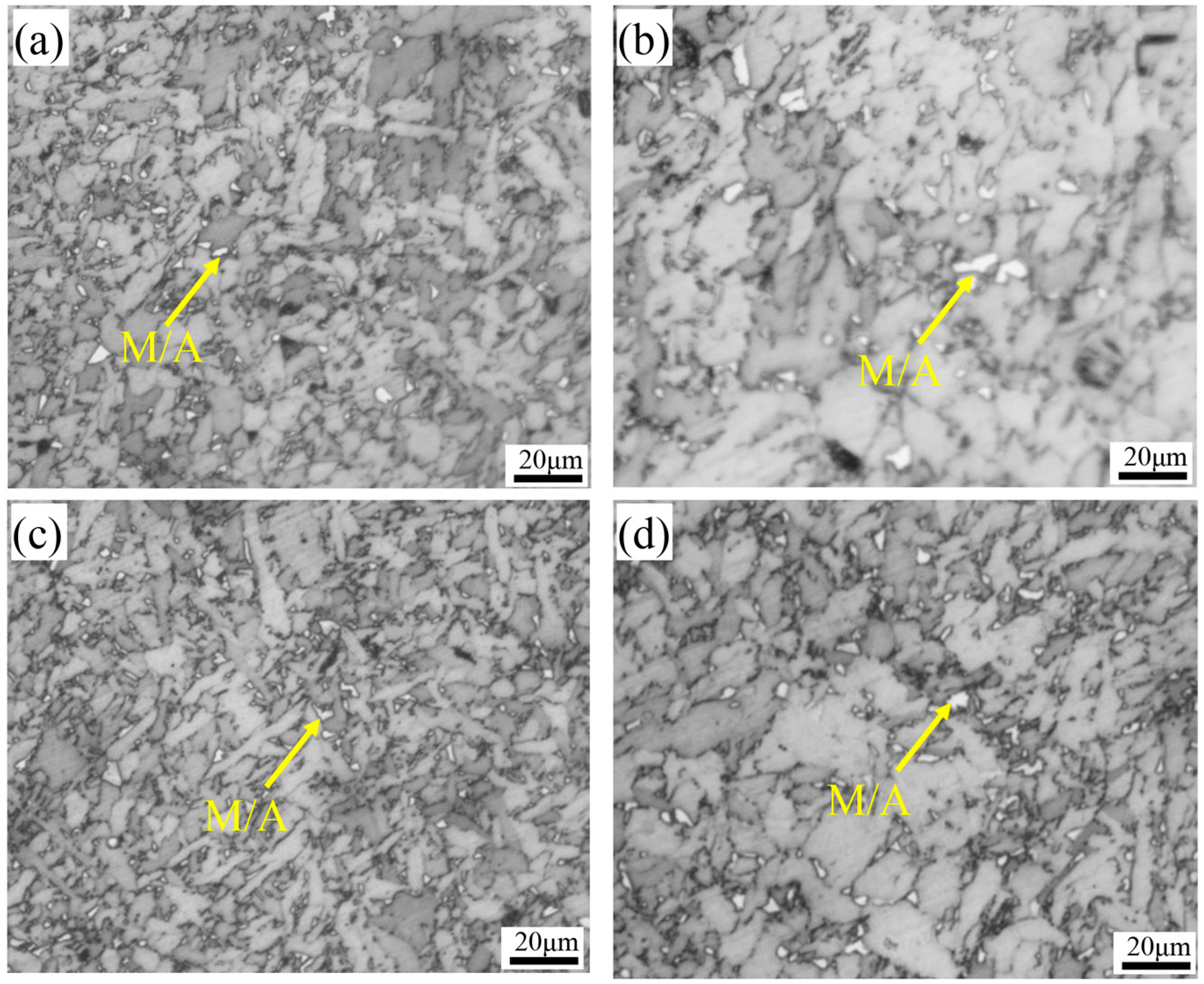
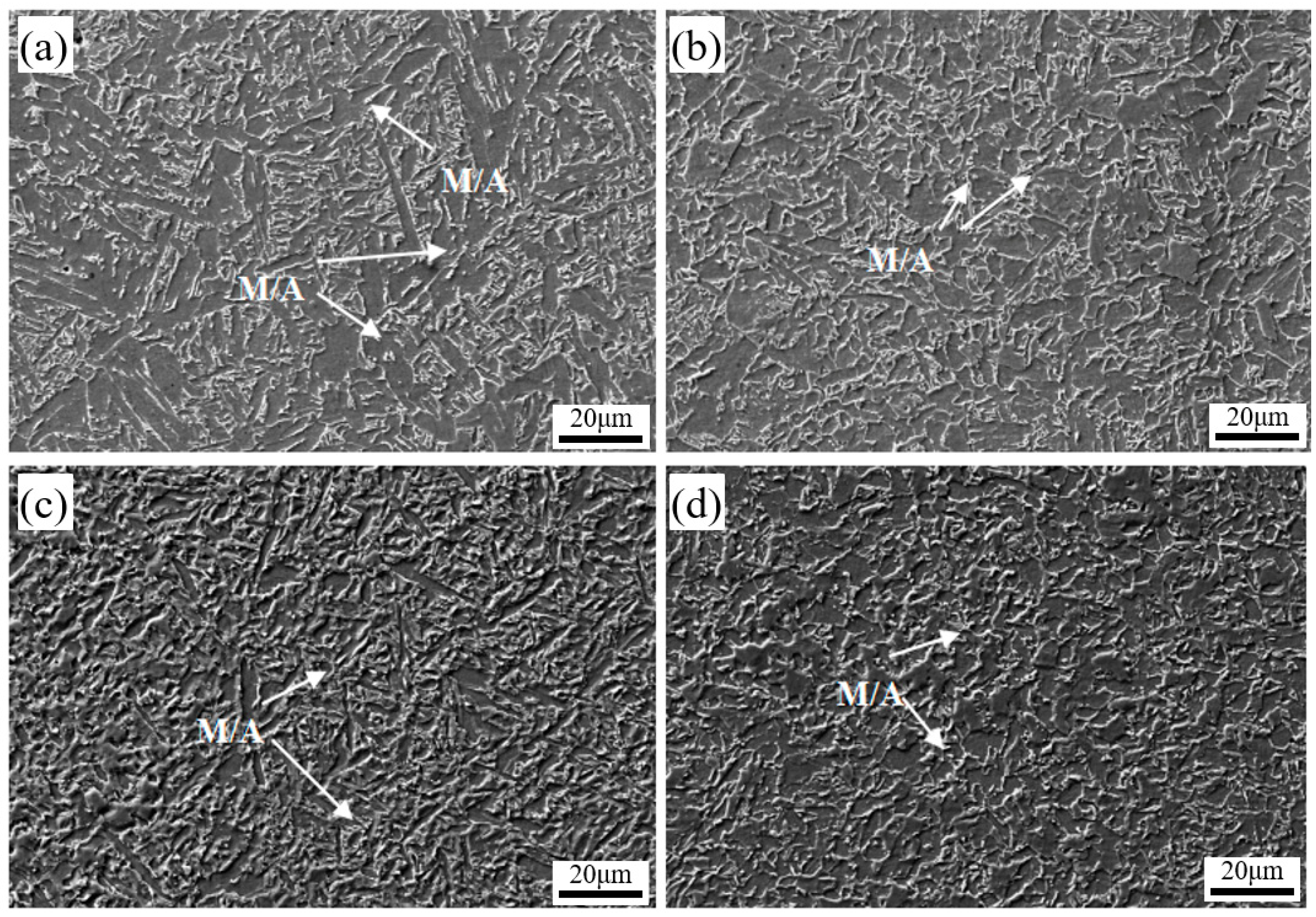
Figure 6 shows the microscopic morphology of the deposited metal’s columnar crystal region, the weld channel heat-affected zone (HAZ), and the M/A (martensite/austenite) constituents under metallographic examination, where the M/A phase appears bright white. It can be observed that, under the thermal cycling of subsequent weld passes, the M/A constituents in the HAZ are more uniformly distributed, smaller in size, and more dispersed compared to those in the columnar crystal region. Moreover, the size of the M/A constituents in the columnar crystal region of the deposited metal is further refined when 0.005 wt% Ce is added, compared to the composition without Ce.
The area fraction and average size of M/A constituents in the heat-affected zone (HAZ) and columnar crystal zone of the weld channel were quantified, and the results are presented in Table 7. The data indicate that the addition of Ce reduces the proportion of M/A constituents in both the HAZ and the columnar crystal zone, from 9.2% to 7.8% and from 5.3% to 4.2%, respectively. Similarly, the average grain size decreases from 1.15 μm to 0.87 μm in the HAZ and from 0.75 μm to 0.69 μm in the columnar crystal zone. These results suggest that a moderate addition of Ce promotes the refinement of M/A constituents. However, the effect of Ce on M/A refinement is somewhat diminished under the influence of welding thermal cycling.
Figure 7 presents the microstructure of the weld columnar crystal region and the heat-affected zone (HAZ) of the weld channel as observed under a scanning electron microscope (SEM). The M/A constituents are clearly visible as bright white, island-like features in the SEM images, predominantly forming on the surfaces of grain boundary ferrite (PF) and acicular ferrite (AF), as well as near prior austenite grain boundaries (PAGB). As shown in Figure 7a,c, the M/A constituents in the weld columnar zone primarily appear as coarse lumps. In contrast, in the HAZ of the weld channel, the M/A constituents are finer and mainly appear as discrete grains, which are more diffusely distributed within the deposited metal, as illustrated in Figure 7b,d.
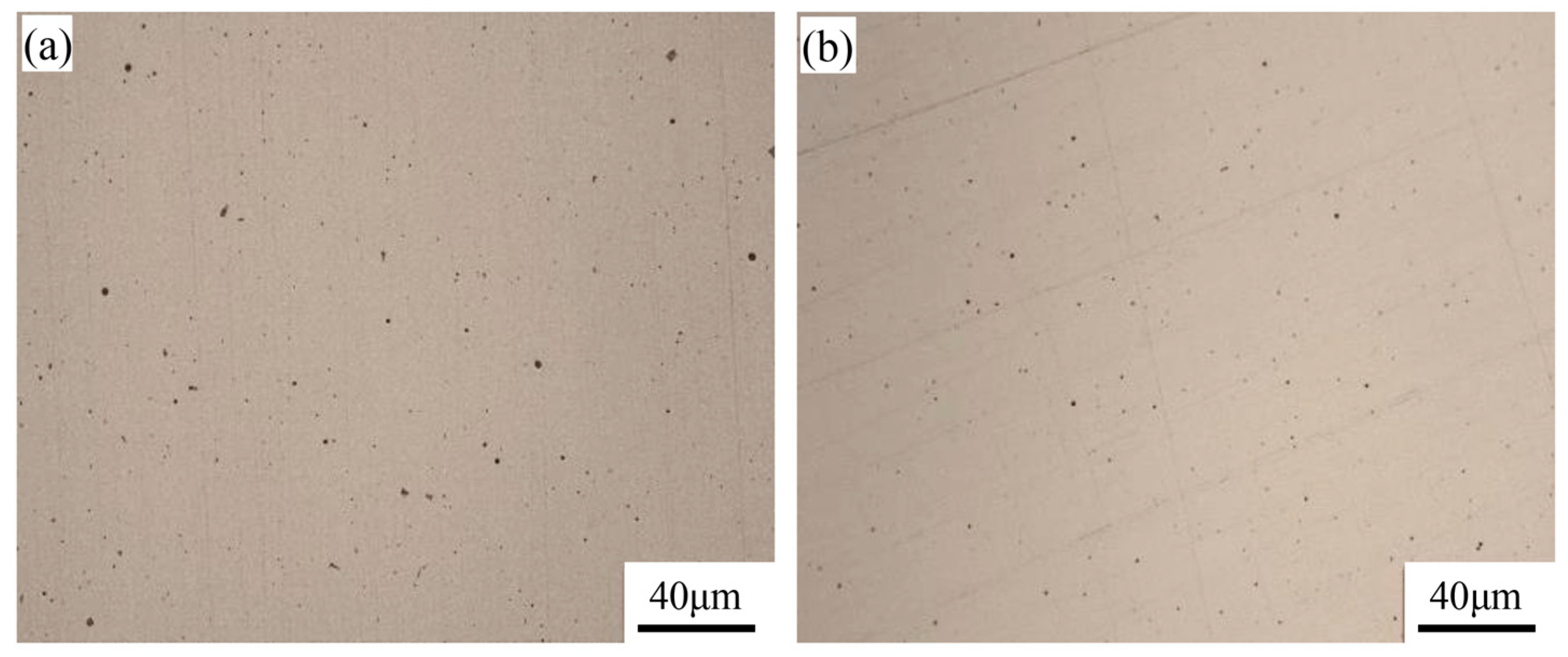
Figure 8a,b illustrates the micromorphology of inclusions in the metallographic phase of deposited metals with different Ce contents (0 wt% Ce and 0.005 wt% Ce, respectively). The inclusions are predominantly spherical and ellipsoidal in shape; however, their size and number vary depending on the Ce content. Compared to the sample without Ce, the deposited metal containing 0.005 wt% Ce exhibits finer inclusions, although the number of inclusions is slightly higher.
The number and size of inclusions were quantified using Image-Pro Plus. A total of 182 and 209 inclusions were observed under a 500× metallurgical microscope, corresponding to average inclusion densities of 4350 and 5225 inclusions per square millimeter, and area fractions of 0.150% and 0.169%, respectively. The average inclusion diameters were 0.473 μm and 0.431 μm, with maximum diameters of 2.69 μm and 2.48 μm, respectively. The detailed statistical results are presented in Table 8. These results indicate that the addition of 0.005 wt% Ce to the deposited metal led to a refinement of inclusions and an increase in their number.
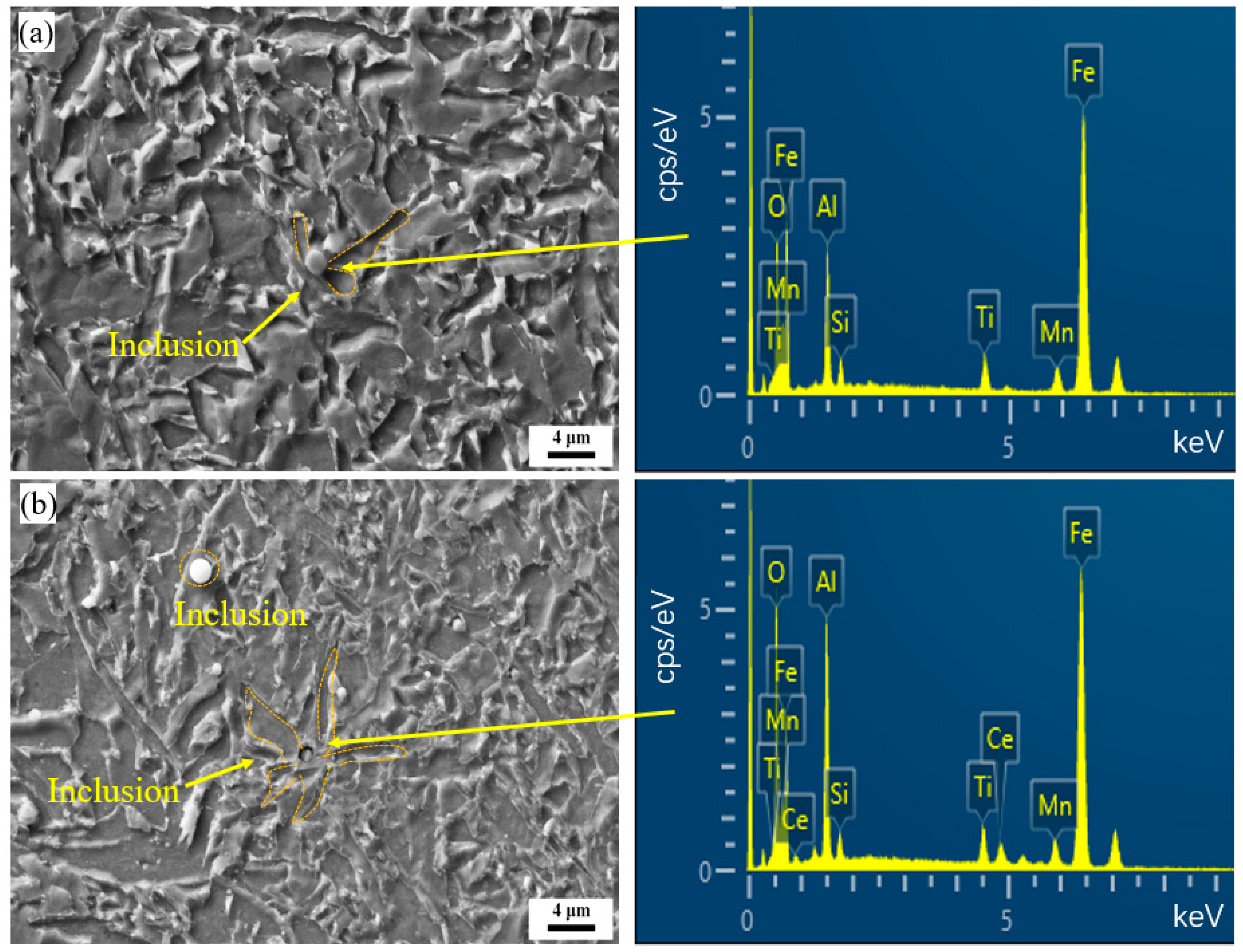
The inclusions in the weld are partially retained due to the transition of molten droplets and metallurgical reactions within the molten pool. During the welding process, various types of inclusions can form as a result of these metallurgical reactions. To investigate the morphology and composition of the inclusions, SEM imaging and EDS analyses were performed. Figure 9a,b presents the SEM observations and corresponding EDS spectra of the inclusions. It is observed that in the 0.005 wt% Ce fused metal, acicular ferrite (AF) grows radially around the inclusions, indicating that the inclusions act as nucleation sites for AF. However, the influence of larger inclusions on AF-assisted nucleation appears to be diminished, as shown in Figure 9b. In the 0 wt% Ce deposited metal, inclusions were also found to induce AF nucleation, as illustrated in Figure 9a. EDS analysis revealed that the inclusions are composite in nature, consisting of multiple elemental constituents. Specifically, inclusions in the 0 wt% Ce weld metal showed enrichment in Si, Mn, Al, Ti, and O, whereas in the 0.005 wt% Ce weld metal, inclusions were additionally enriched with Ce alongside Si, Mn, Al, Ti, and O.
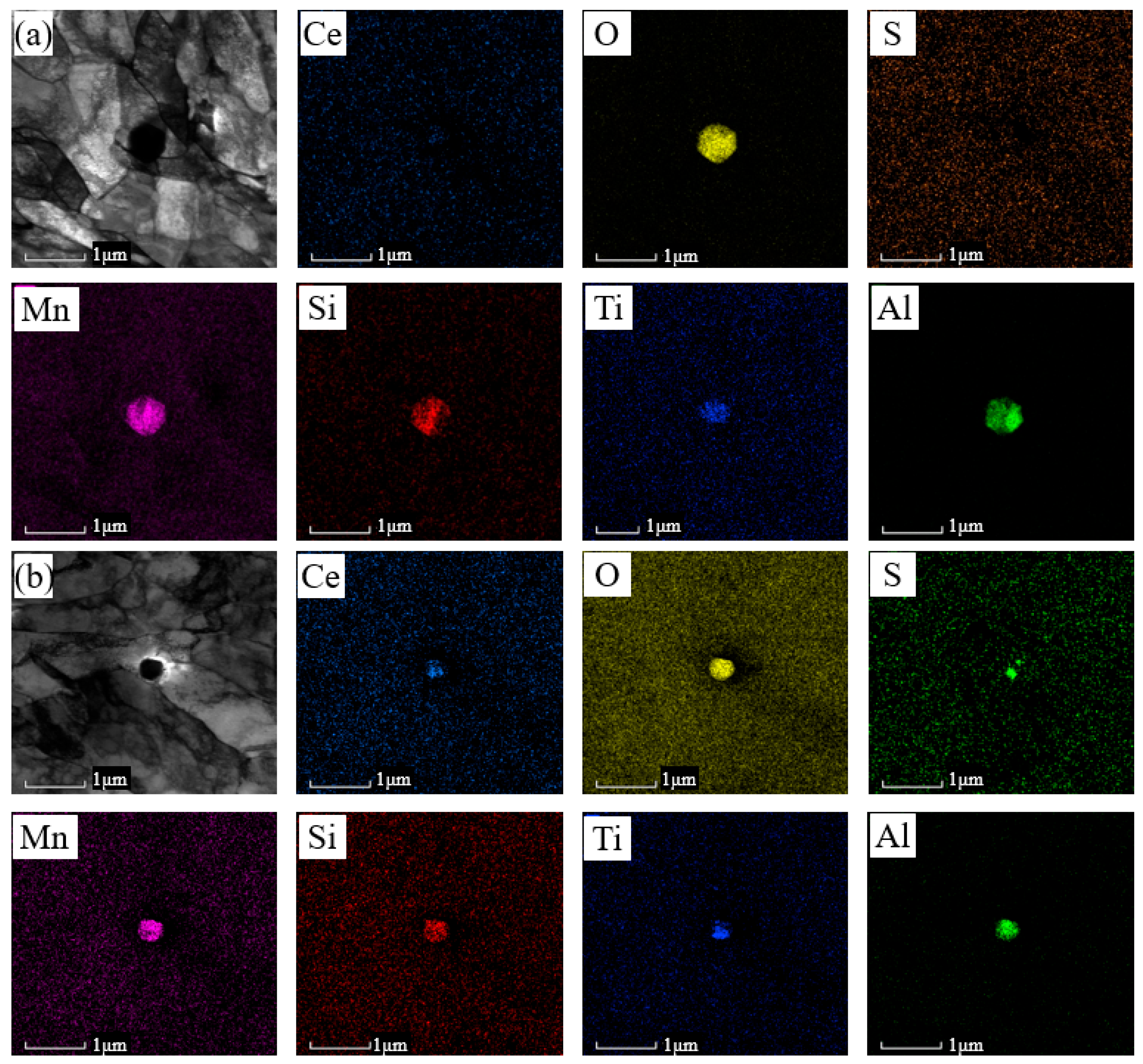
Figure 10 presents the microscopic morphology of the inclusions observed under TEM, along with a selective surface scan to examine the elemental distribution and composition. As shown in Figure 10a, elements such as Si, Mn, Al, Ti, and O are primarily concentrated at the center of the 0 wt% Ce melt-deposited metal inclusions. Based on the observed elemental distribution and the likely metallurgical reactions, it can be inferred that the 0 wt% Ce melt-deposited metal inclusions are composite in nature, consisting of SiO2, MnO, Al2O3, and TiOx, with TiOx forming the core.
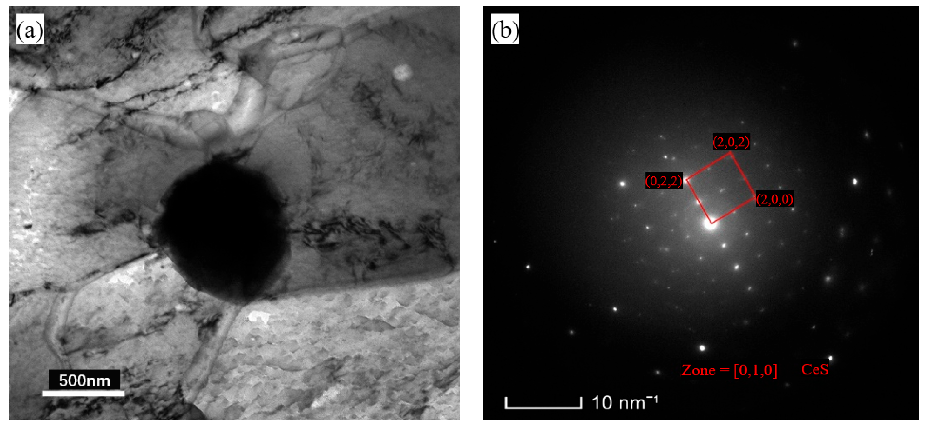
In addition to Si, Mn, O, Ti, Al, and Ce, the edges of the elemental metal inclusions in the presence of 0.005 wt% Ce also show slight enrichment of S, leading to the formation of “sulfur-rich blocks.” In order to determine the presence form of the S element, the inclusions were selected for diffraction spot testing and physical phase analysis [21] and the results are shown in Figure 11, which confirms that the S element and Ce element form CeS to be retained in the weld instead of MnS. W.G. Wilson et al. [22] proposed a model for the growth of Ce-based inclusions by analyzing the free energy of formation for various inclusions and the critical solute elemental activity required for each reaction. According to this model, elemental Ce initially undergoes oxidation with O to produce Ce2O3 rather than CeO2, primarily due to the low oxygen content in the steel and welds, which inhibits CeO2 formation. Subsequently, Ce participates in oxygen-sulfur reactions to form Ce2O2S [23,24], and ultimately CeS. The presence of CeS observed in this study supports this sequence, suggesting that the 0.005 wt% Ce-containing fused metal inclusions are complex SiO2-MnO-Al2O3-TiOx-Ce2O3-Ce2O2S-CeS composites, with Ce2O3 and TiOx serving as the nucleation cores.

3.2. Impact Properties and Fracture Characterisation of Welds

Figure 12 presents the mechanical properties of the deposited metal with varying Ce content. It can be observed that the addition of Ce leads to an increasing trend in impact performance. Specifically, compared to the deposited metal without Ce, the impact work is enhanced by 80 J with the incorporation of Ce.
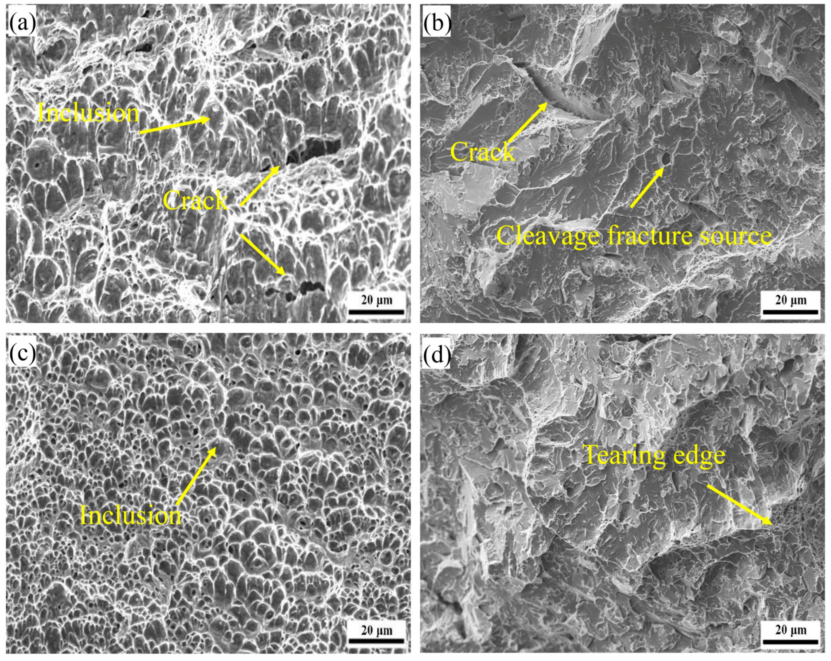
Under the action of an applied load, an impact specimen experiences local tensile and compressive stresses, as well as elastic and plastic deformations. The resulting fracture morphology can be divided into three distinct regions: the shear lip, the fibrous zone, and the radial zone [25]. During crack propagation, compressive stresses act to slow crack growth, leading to localized plastic deformation and the formation of a secondary fibrous zone. Figure 13a–d present the microscopic morphology of the fibrous and radial zones in the deposited metals with 0 wt% Ce and 0.005 wt% Ce, respectively. The observed fracture mode is identified as transgranular [26].
In the 0.005 wt% Ce deposited metal, the fracture surface in the fiber zone exhibits a large number of small, uniformly sized, isometric ligamentous nests. [27] These ligamentous nests are predominantly spherical and relatively deep, with some nests containing observable inclusions (Figure 13c). This fiber zone is primarily indicative of the material’s toughness. In contrast, the radiation zone displays typical quasi-cleavage fracture characteristics, characterized by distinct river patterns and tear ridges, with a small number of ductile dimples present on the tear ridges. The river patterns have an average size of 9.3 μm. Overall, the fracture morphology of the 0.005 wt% Ce deposited metal suggests favorable impact properties.
In the fibrous region of the fracture of 0 wt% Ce, the ligamentous nests become larger, formed by the aggregation of several smaller ligamentous nests. In the radial region, the average size of the river pattern is 12.3 μm. A small number of short, coarse cracks are also observed on the microfracture surfaces. Additionally, river patterns originating from inclusions, which act as centers of disintegration, are evident on the fracture surfaces. These observations indicate that inclusions serve as initiation sites for the disintegration-type fractures (see Figure 13a,b).

3.3. Microstructural Evolution Analysis

Statistical analysis of the microstructural distribution indicates that the proportion of acicular ferrite (AF) within the columnar grain region of the deposited metal and the heat-affected zone of the weld bead increases with the addition of Ce. This enhancement is primarily attributed to the formation of cerium-induced metamorphic inclusions. As shown in Figure 9 and Figure 10, the inclusions in the deposited metal without Ce addition predominantly consist of composite inclusions with a TiOx core surrounded by MnO, SiO2, and Al2O3. In contrast, in the Ce-added deposited metal, the inclusions comprise composite structures with a TiOx and Ce2O3 core, encased by MnO, SiO2, Al2O3, Ce2O2S, and Ce2O3. A schematic representation of these inclusion structures is presented in Figure 14.
Surface inclusions play a crucial role in the nucleation of acicular ferrite (AF), according to the theory of inclusion-induced nucleation mismatch [22]. The smaller the lattice mismatch between ferrite and inclusions, the lower the interfacial energy required for nucleation. Consequently, the nucleation driving force decreases, making nucleation more favorable. Compared to quasi-polygonal ferrite (QPF), AF experiences less distortion during nucleation around inclusions, further facilitating its formation at these sites. The lattice constants of various inclusions with respect to ferrite are as follows: Al2O3 (4.7 Å), SiO2 (4.9 Å), MnO (4.5 Å), TiO2 (3.88 Å), Ce2O3 (0.57 Å), CeS (4.0 Å), and Ce2O2S (2.88 Å). Notably, Ce2O3 and Ce2O2S exhibit significantly lower lattice mismatch with ferrite compared to Al2O3, SiO2, MnO, and TiO2, indicating that they are more effective as nucleation sites for AF. The addition of cerium-based filler metal promotes the formation of complex composite inclusions, including SiO2-MnO-Al2O3-TiOx-Ce2O3-Ce2O2S-CeS, which increases the number of available nucleation sites for AF and consequently enhances its content.
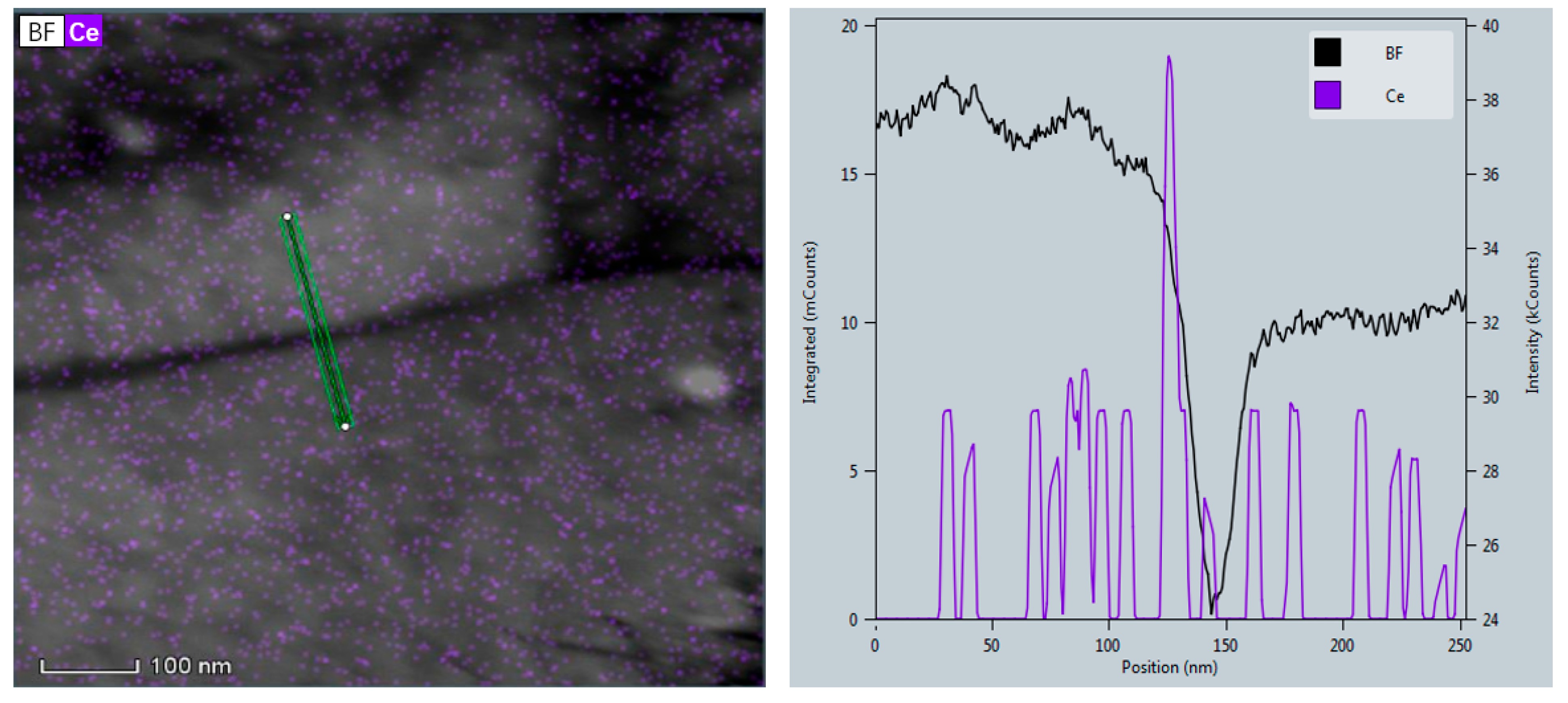
The increased AF content restricts the available growth space for QPF and PF, which compete with AF during the growth process. Simultaneously, Ce segregate at grain boundaries, reducing the segregation of impurities. This reduction lowers the grain boundary energy and alters the growth environment for PF. As illustrated in Figure 15, the combined effects of limited growth space and Ce-induced grain boundary stabilization result in a decrease in the content of both QPF and PF.
During the solid-state phase transformation within the molten pool, the γ→α transformation occurs. Carbon atoms diffuse outward from the ferrite, leading to the formation of carbon-enriched zones near prior austenite grain boundaries (PAGB) and acicular ferrite (AF) grain boundaries. This localized carbon enrichment enhances the stability of austenite. As the temperature decreases, a portion of the austenite transforms into martensite, resulting in a microstructure composed of martensite and retained austenite (M/A). The addition of Ce reduces the diffusion rate of carbon and simultaneously increases the fraction of AF. Compared to quasi-polygonal ferrite (QPF), AF has a greater capacity to accommodate carbon, which suppresses the outward diffusion of carbon. Consequently, this leads to a reduction in carbon-enriched zones and promotes the formation of finer M/A constituents (Figure 6 and Figure 7).

3.4. Impact Fracture Analysis

As shown in Figure 12, the impact toughness of the weld metal increases significantly with rising Ce content. Impact toughness is generally understood to consist of two components: crack initiation energy and crack propagation energy [28]. Therefore, the toughening effect of Ce was analyzed by examining its influence on both crack initiation and crack propagation mechanisms.
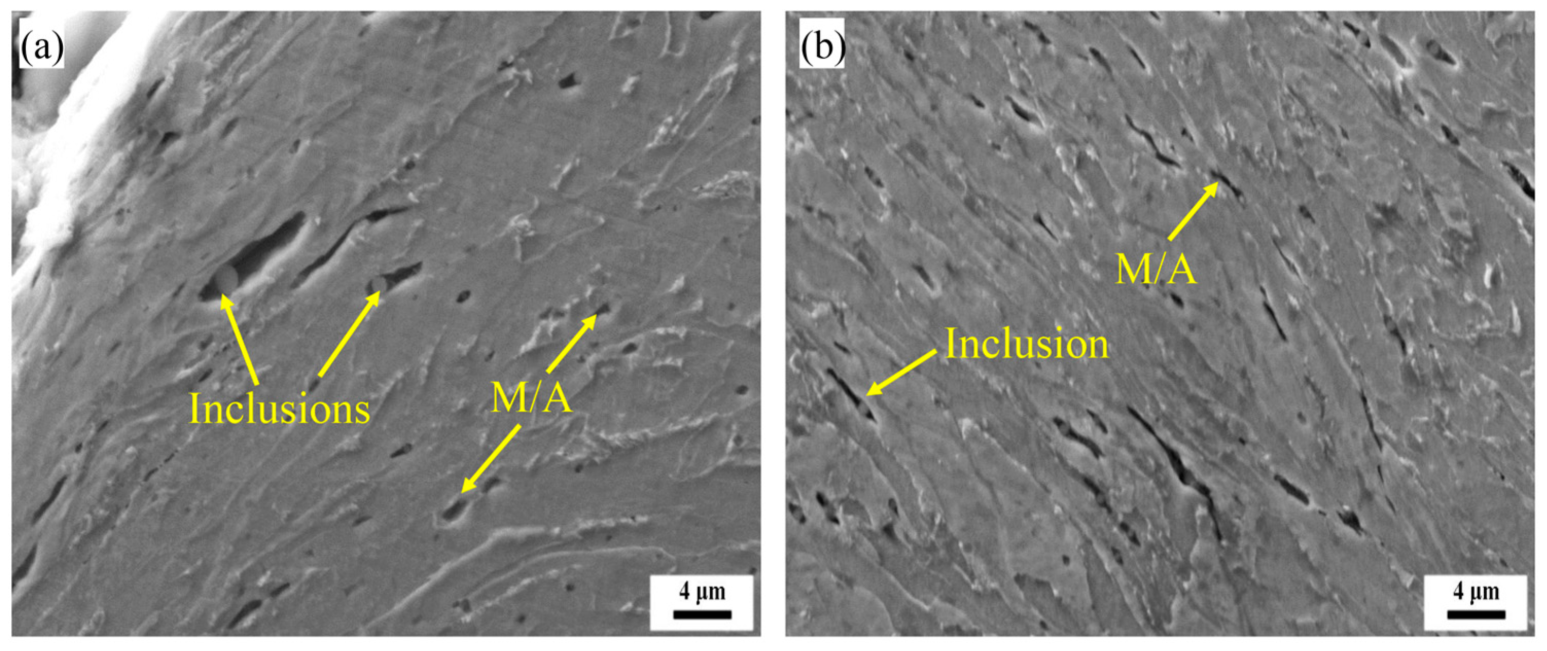
To investigate the fracture behavior of the deposited metal, longitudinal sampling was conducted on the fracture surfaces to examine crack propagation beneath the fibrous zones. The results are presented in Figure 16. Microcracks and microvoids were observed beneath the fracture surfaces of both the 0 wt% Ce and 0.005 wt% Ce fiber zones, primarily attributed to hard-phase inclusions and martensite/austenite (M/A) constituents. Notably, compared with the Ce-free fibers, the Ce-containing fibers exhibited greater plastic deformation prior to crack initiation, and the microcracks and microvoids in these fibers were significantly smaller in size than those observed in the Ce-free specimens.
In low-alloy steels, hard phase inclusions and martensite/austenite (M/A) constituents play a significant role in determining the critical stresses for micro-pore and micro-crack nucleation. A lower critical stress corresponds to a higher susceptibility to crack initiation. The critical stresses for micro-pore and micro-crack nucleation are defined by Equations (9) and (10), respectively [14]. According to these expressions, the critical stresses are closely related to the size of inclusions or M/A constituents. As the transition Ce content in the weld increases, both the size of inclusions and M/A constituents are refined (as illustrated in Figure 6 and Figure 8). This refinement leads to an increase in the critical stresses for microporosity and micro-crack nucleation, thereby enhancing the energy required for crack initiation.
σ v = 6 γ E q d
where σ v —Critical stress for microporous nucleation;
  • d —Equivalent diameter of brittle phase structures such as inclusions or M/A components;
  • E —Young’s modulus of the particle;
  • q —Stress concentration factor at inclusions;
  • γ —Surface energy of inclusions.
σ C = ( π E γ ( 1 v 2 ) d 0 ) 1 / 2
where σc—Critical fracture stress;
  • E—Young’s modulus;
  • γ—Effective surface energy at fracture;
  • ν—Poisson ratio;
  • d0—Microcrack dimensions.
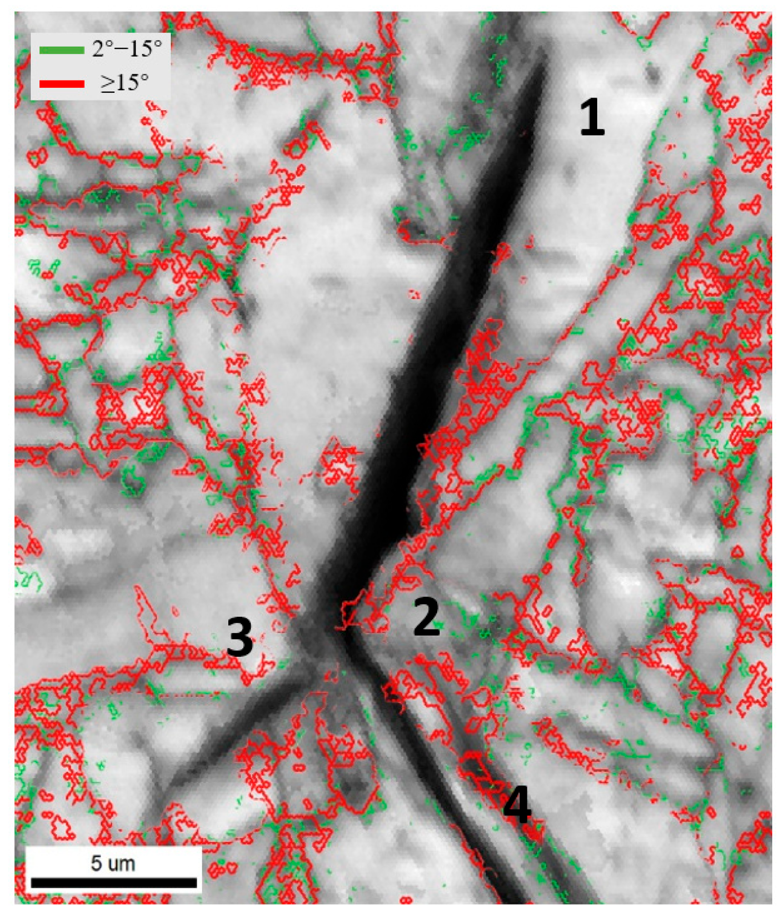
Research indicates that during crack propagation, austenitic grain boundaries, fine martensite/austenite (M/A) phase boundaries, and high-angle grain boundaries between grains of different orientations act to impede crack growth [29,30]. The secondary cracks beneath the radiating zone of the 0.005 wt.% carbon impact fracture surface were characterized using EBSD, with results shown in Figure 17. Grain boundaries with misorientation angles between 2° and 15° were defined as low-angle grain boundaries (marked in green), while those with angles greater than 15° were defined as high-angle grain boundaries (marked in red). In Figure 17, the secondary crack initiates at position 1, exhibiting a coarse fracture with strong propagation capability. At position 2, the crack undergoes deflection and branches into two extensions propagating toward positions 3 and 4. The secondary crack becomes finer, its propagation capability diminishes, and it terminates at position 3. Notably, position 2 corresponds to a grain trilateral boundary with a high-angle grain boundary. The crack deflection and reduction in crack width at this location indicate that the high-angle grain boundary consumes crack propagation energy, thereby hindering crack extension and improving impact performance. The density of high-angle grain boundaries thus directly influences the amount of energy required for crack propagation.
In 0.005 wt.% Ce-modified weld metal, Ce acts as an inclusion to promote the nucleation of columnar grains and refine the austenite in the weld heat-affected zone (HAZ). As a result, the fractions of acicular ferrite (AF) in the weld metal and HAZ increased from 52% and 20% to 83% and 37%, respectively, while the proportions of polygonal ferrite (PF) and quasi-polygonal ferrite (QPF) significantly decreased. The increased AF content subdivides the austenite grains into finer segments, refining the microstructure. Furthermore, the addition of Ce increased the proportion of high-angle grain boundaries in the columnar zone from 59.2% to 80.1%, and in the HAZ from 32% to 46%. This increase in high-angle grain boundary density enhances resistance to crack propagation and raises the associated crack extension work.

4. Conclusions

This study investigated the effect of Ce addition (0.14 wt.% Ce) on the microstructure and impact toughness of submerged arc weld metals. Key findings are:
(1)
The weld metal consists of a columnar crystal zone and a heat-affected zone. The columnar zone mainly contains acicular ferrite, grain boundary ferrite, polygonal ferrite, granular bainite, and M/A constituents, while the heat-affected zone has a coarser microstructure dominated by polygonal and acicular ferrite, granular bainite, and minor M/A constituents.
(2)
Increasing Ce from 0 to 0.005 wt% in the weld metal raises the acicular ferrite fraction in the columnar zone and heat-affected zone from 52% and 20% to 83% and 37%, respectively, while reducing polygonal and grain boundary ferrite. Large-angle grain boundaries also increase from 59.2% to 80.1%.
(3)
Ce addition refines M/A constituents and inclusions, enhancing critical fracture stress and crack-initiation resistance. The increased acicular ferrite and large-angle grain boundaries improve crack-propagation resistance, resulting in a notable rise in low-temperature (−20 °C) impact energy from 117 J to 197 J.
Overall, Ce effectively refines weld microstructure and significantly improves low-temperature impact toughness.

Author Contributions

Conceptualization, Q.W. (Qingfeng Wang); methodology, Q.W. (Qingfeng Wang) and Y.W.; software, J.Q.; validation, Q.W. (Qiuming Wang); formal analysis Q.W. (Qiuming Wang); investigation, Y.W.; resources, Q.W. (Qingfeng Wang); data curation, J.Q.; writing—original draft preparation, Q.W. (Qingfeng Wang) and Y.W.; writing—review and editing, Q.W. (Qingfeng Wang) and Y.W.; visualization, Q.W. (Qingfeng Wang) and J.Q.; supervision, Q.W. (Qingfeng Wang); project administration, Q.W. (Qingfeng Wang); funding acquisition, Q.W. (Qingfeng Wang). All authors have read and agreed to the published version of the manuscript.

Funding

This work was supported by the National Natural Science Foundation of China (52127808) and National Key Research and Development Program of China (Grant No. 2017YFB0304800 and Grant No. 2017YFB0304802 for the second sub project).

Data Availability Statement

The original contributions presented in the study are included in the article. Further inquiries can be directed to the corresponding author.

Conflicts of Interest

Author Yuwei Wang was employed by the company Jiangsu Fuermu Welding Corporation. The remaining authors declare that the research was conducted in the absence of any commercial or financial relationships that could be construed as a potential conflict of interest.

References

  1. De Baere, K.; Verstraelen, H.; Willemen, R.; Smet, J.-P.; Tchuindjang, J.T.; Lecomte-Beckers, J.; Lenaerts, S.; Meskens, R.; Jung, H.G.; Potters, G. Assessment of corrosion resistance, material properties, and weldability of alloyed steel for ballast tanks. J. Mar. Sci. Technol. 2017, 22, 176–199. [Google Scholar] [CrossRef]
  2. Hao, X.; Dong, J.; Wei, J.; Ke, W.; Wang, C.; Xu, X.; Ye, Q. Influence of microstructure of AH32 corrosion resistant steel on corrosion behavior. Acta Met. Sin 2012, 48, 534–540. [Google Scholar] [CrossRef]
  3. Liu, W.; Zhao, H.; Wang, B.; Tian, Y. Impact of Mo/Ni alloying on microstructural modulation and low-temperature toughness of high-strength low-alloy steel. J. Iron Steel Res. Int. 2024, 31, 1746–1762. [Google Scholar] [CrossRef]
  4. Li, Y.; Baker, T.N. Effect of morphology of martensite–austenite phase on fracture of weld heat affected zone in vanadium and niobium microalloyed steels. Mater. Sci. Technol. 2010, 26, 1029–1040. [Google Scholar] [CrossRef]
  5. Honma, Y.; Sasaki, G.; Hashi, K.; Minami, F. Improving the toughness of the weld-heat-affected zone of Cu-containing low-alloy steel for offshore applications by optimizing chemical composition. J. Eng. Mater. Technol. 2021, 143, 011006. [Google Scholar] [CrossRef]
  6. Fu, W.; Li, C.; Di, X.; Fu, K.; Gao, H.; Fang, C.; Lou, S.; Wang, D. Refinement mechanism of nanoscale Cu-rich precipitates by Mo addition and its effect on strength-toughness of Cu-bearing low carbon high strength steel. Mater. Sci. Eng. A 2022, 849, 143469. [Google Scholar] [CrossRef]
  7. Bhattacharya, A.; Biswal, S.; Barik, R.K.; Mahato, B.; Ghosh, M.; Mitra, R.; Chakrabarti, D. Comparative interplay of C and Mn on austenite stabilization and low temperature impact toughness of low C medium Mn steels. Mater. Charact. 2024, 208, 113658. [Google Scholar] [CrossRef]
  8. Yu, H.; Zhang, T.; Chen, Y.; Wang, W.; Wu, W. Effect of CeO2 on microstructures and mechanical properties of welded high-strength steel weld metal. Mater. Res. Express 2021, 8, 016515. [Google Scholar] [CrossRef]
  9. Wang, C.; Di, X.; Dai, L.; Liu, J.; Han, J.; Yang, X.; Yang, Z.; Cui, S.; Zhang, C.; Ma, Z.; et al. Synchronously improving strength and toughness for pipeline steel weld via cerium adding. Int. J. Press. Vessel. Pip. 2025, 215, 105466. [Google Scholar] [CrossRef]
  10. NB/T 47014-2011; Welding Procedure Qualification for Pressure Equipment. National Energy Administration: Beijing, China, 2011.
  11. GB/T 228.1-2021; Metallic Materials—Tensile Testing—Part 1: Method of Test at Room Temperature. State Administration for Market Regulation, Standardization Administration of PRC: Beijing, China, 2021.
  12. GB/T 229-2020; Metallic Materials—Charpy Pendulum Impact Test Method. State Administration for Market Regulation. Standardization Administration of PRC: Beijing, China, 2020.
  13. Yin, T.W.; Shen, Y.F.; Xue, W.Y.; Jia, N.; Zuo, L. Ce addition enabling superior strength and ductility combination of a low-carbon low-manganese transformation-induced plasticity steel. Mater. Sci. Eng. A 2022, 849, 143474. [Google Scholar] [CrossRef]
  14. Na, X.; Lei, C.; Luo, W. Microstructure and Mechanical Properties of GMAW+ SAW Joint of Heavy Thickness High Strength Marine Engineering Steel DH36. Silicone Mater. 2022, 36, 615–620+629. [Google Scholar] [CrossRef]
  15. Liang, J.M.; Tang, D.; Wu, H.B.; Zhang, P.C.; Liu, W.; Mao, H.Y.; Liu, X.T. Corrosion behaviors of Cr low-alloy steel in bottom plate environment of cargo oil tanks. J. South China Univ. Technol. Nat. Sci. 2013, 41, 72–98. [Google Scholar]
  16. Kozlov, L.J.; Vorobyev, A.P. The role of rare-earth metals in the process of spheroidal graphite formation. Cast Met. 1991, 4, 7–11. [Google Scholar] [CrossRef]
  17. Jia, S.; Ma, Q.; Hou, Y.; Li, B.; Zhang, H.-S.; Liu, Q.-Y. Changes in microstructure and properties of weld heat-affected zone of high-strength low-alloy steel. J. Iron Steel Res. Int. 2024, 31, 2041–2052. [Google Scholar] [CrossRef]
  18. Ning, Y.A.N.; Shengfu, Y.U.; Ying, C. In situ observation of austenite grain growth and transformation temperature in coarse grain heat affected zone of Ce-alloyed weld metal. J. Rare Earths 2017, 35, 203–210. [Google Scholar] [CrossRef]
  19. Liang, G.L.; Yang, S.W.; Wu, H.B.; Liu, X. Microstructure and mechanical performances of CGHAZ for oil tank steel during high heat input welding. Rare Met. 2013, 32, 129–133. [Google Scholar] [CrossRef]
  20. Li, Y.; Huang, M. A method to calculate the dislocation density of a TWIP steel based on neutron diffraction and synchrotron X-ray diffraction. Acta Met. Sin 2020, 56, 487–493. [Google Scholar]
  21. Zhang, J.; Li, G.; Wang, H.; Wan, X.; Hu, M.; Cao, Y. Effect of cerium on microstructure and microsegregation behavior of novel cryogenic high-Mn austenitic steel weld metal. Mater. Charact. 2022, 194, 112427. [Google Scholar] [CrossRef]
  22. Wilson, W.G.; Kay, D.A.R.; Vahed, A. The use of thermodynamics and phase equilibria to predict the behavior of the rare earth elements in steel. JOM 1974, 26, 14–23. [Google Scholar] [CrossRef]
  23. Khalaj, G.; Yoozbashizadeh, H.; Khodabandeh, A.; Tamizifar, M. Austenite grain growth modelling in weld heat affected zone of Nb/Ti microalloyed linepipe steel. Mater. Sci. Technol. 2014, 30, 424–433. [Google Scholar] [CrossRef]
  24. Curry, D.A.; Knott, J.F. Effects of microstructure on cleavage fracture stress in steel. Met. Sci. 1978, 12, 511–514. [Google Scholar] [CrossRef]
  25. Thewlis, G. Effect of cerium sulphide particle dispersions on acicular ferrite microstructure development in steels. Mater. Sci. Technol. 2006, 22, 153–166. [Google Scholar] [CrossRef]
  26. Wang, G.; Kang, D.; Ye, Y.; Deng, D. Effect of Cr addition on microstructure, mechanical properties, and corrosion behavior of weld metal in weathering steel of high-speed train bogie. Weld. World 2024, 68, 3115–3128. [Google Scholar] [CrossRef]
  27. Zhang, J.; Li, G.; Wang, H.; Wan, X.; Hu, M.; Cao, Y. Achieving superior cryogenic impact toughness and sufficient tensile properties in a novel high-Mn austenitic steel weld metal via cerium addition. J. Mater. Res. Technol. 2023, 23, 5016–5030. [Google Scholar] [CrossRef]
  28. Maalekian, M.; Radis, R.; Militzer, M.; Moreau, A.; Poole, W. In situ measurement and modelling of austenite grain growth in a Ti/Nb microalloyed steel. Acta Mater. 2012, 60, 1015–1026. [Google Scholar] [CrossRef]
  29. Yan, N.; Yu, S.F.; Chen, Y. Inclusions, microstructure and properties of flux copper backing submerged arc weld metal. Sci. Technol. Weld. Join. 2015, 20, 418–424. [Google Scholar] [CrossRef]
  30. Stone, R.H.V.; Cox, T.B.; Low, J.R.; Psioda, J.A. Microstructural aspects of fracture by dimpled rupture. Int. Met. Rev. 1985, 30, 157–180. [Google Scholar] [CrossRef]
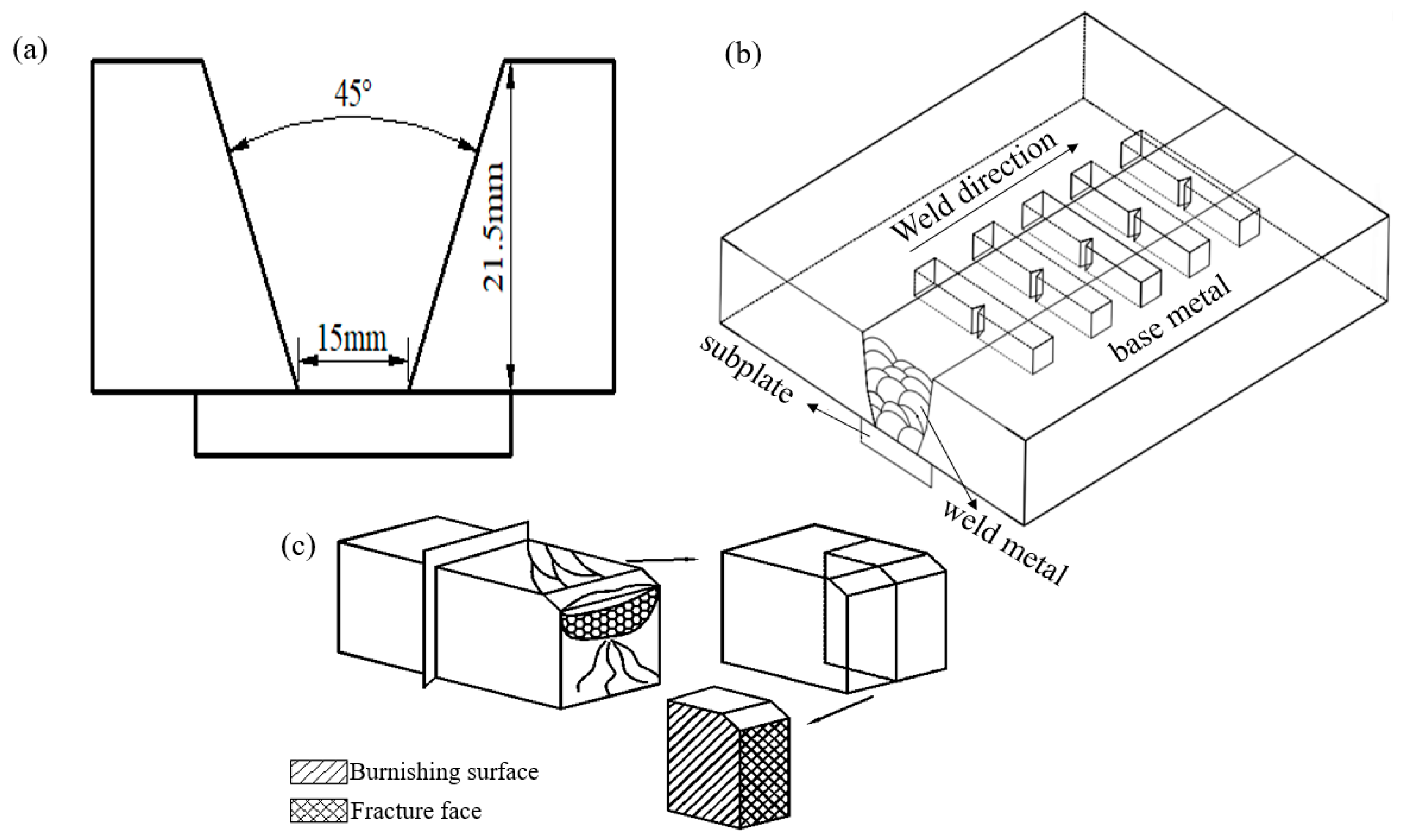
Figure 1. Groove Types for Deposition Test Specimens (a), Schematic diagram for impact test specimen extraction from weld metal (b), Schematic diagram for microstructure and impact fracture surface characterization sampling (c).
Metals 15 01289 g001
Figure 2. Macroscopic morphology of weld metal deposited by Ce-free (a) and 14Ce-containing (b) welding wire.
Metals 15 01289 g002
Figure 3. Microscopic morphology of the deposited metal microstructure under OM. Without Ce: (a) columnar crystal region, (b) heat affected zone of the weld channel. With 0.005 wt% Ce: (c) columnar crystal region, (d) heat affected zone of the weld channel.
Metals 15 01289 g003
Figure 4. IPF diagrams of deposited metal with different Ce contents. Without Ce: (a) cylindrical zone, (b) heat affected zone of the welded channel. With 0.005 wt% Ce: (c) cylindrical zone, (d) heat affected zone of the welded channel.
Metals 15 01289 g004
Figure 5. Microstructure and morphology of the deposited metal under TEM, 0.005 wt% Ce: (a) Columnar crystal region, (b) Heat affected zone of the welded channel; (c) Morphology of the M/A component.
Metals 15 01289 g005
Figure 6. Microscopic morphology of the deposited metal M/A group elements under OM, 0 wt% Ce: (a) columnar crystal area, (b) heat affected zone of the welded channel; 0.005 wt% Ce: (c) columnar crystal area, (d) heat affected zone of the welded channel.
Metals 15 01289 g006
Figure 7. SEM microstructure of the deposited metal, 0 wt% Ce: (a) columnar crystal region, (b) heat affected zone of the welded channel; 0.005 wt% Ce: (c) columnar crystal region, (d) heat affected zone of the welded channel.
Metals 15 01289 g007
Figure 8. Microscopic morphology under OM of deposited metal inclusions: (a) 0 wt% Ce; (b) 0.005 wt% Ce.
Metals 15 01289 g008
Figure 9. SEM morphology and EDS analysis of deposited metal inclusions: (a) 0 wt% Ce; (b) 0.005 wt% Ce.
Metals 15 01289 g009
Figure 10. Morphology and elemental distribution of deposited metal inclusions under TEM: (a) 0 wt% Ce; (b) 0.005 wt% Ce.
Metals 15 01289 g010
Figure 11. Observation of inclusions in 0.005 wt% Ce weld (a) and physical phase calibration of diffraction spots (b).
Metals 15 01289 g011
Figure 12. Impact property test results of weld metal.
Metals 15 01289 g012
Figure 13. SEM observation of fibre and radiation zones of deposited metal fracture. With 0 wt% Ce: (a) fibre zone, (b) radiation zone. With 0.005 wt% Ce: (c) fibre zone, (d) radiation zone.
Metals 15 01289 g013
Figure 14. Schematic diagram of inclusion structure.
Metals 15 01289 g014
Figure 15. TEM observation of Ce segregation at grain boundaries.
Metals 15 01289 g015
Figure 16. Observation of fracture behaviour beneath the fibrous zone of the impact fracture surface: (a) 0 wt% Ce; (b) 0.005 wt% Ce.
Metals 15 01289 g016
Figure 17. EBSD observation of secondary cracking below the emission zone of the 0.005 wt% Ce fracture.
Metals 15 01289 g017
Table 1. Chemical Composition of Welding Wire Steels (wt.%).
Welding Wire TypeCSiMnPSNiCuMoTiCe
Ce-free0.0710.411.510.0100.0040.400.280.180.041/
14Ce0.0680.391.500.0090.0030.410.290.170.0420.14
Table 2. Base Material Chemical Composition (wt.%).
CSiMnPSNbVTiMoNiCuSnAlFeCEVPcm
0.0880.311.380.0090.0020.020.0420.020.130.210.200.020.036Bal.0.4260.191
Table 3. Chemical Composition of Flux (wt.%).
MgCaOSiO2TiO2Al2O3MnOCaF2PSOthers
335142162250.0260.017Bal.
Table 4. Welding Parameters for Welding Wire Deposition Test.
Interlayer
Temperature
(°C)
Current
(A)
Voltage
(V)
Welding
Speed
(cm/min)
Welding
Heat Input
(kJ/cm)
Number of
Welding Passes
120 ± 1060032383013
Table 5. Chemical Composition of Weld Metal.
Welding Wire TypeCSiMnPSNiCuMoTiCeFe
Ce-free0.0610.381.470.0110.0040.400.280.180.016/Bal.
14Ce0.0630.411.490.0100.0030.410.290.170.0180.005Bal.
Table 6. Statistics on the Percentage of Organisation in the Columnar Crystal Zone of the Deposited Metal and the Heat-Affected Zone of the Weld Channel (%).
Ce Content in WeldColumnar Crystal Region (Math.)Heat-Affected Zone of the Weld Channel
AFPFQPFAFPFQPF
Ce-free52261220/51
0.005 wt%834837/63
Table 7. Deposited Metal M/A Group Element Size Statistics.
Ce Content of WeldColumnar Crystal Region (Math.)Heat-Affected Zone of the Weld Channel
fM/A/%dM/A/μmfM/A/%dM/A/μm
0 wt.%9.21.155.30.75
0.005 wt.%7.80.874.20.65
Table 8. Deposited Metal Inclusions Size Statistics.
Ce Content of WeldArea
Proportion/%
Average
Diameter/um
Maximum
Diameter/um
Area
Destiny/mm−2
Ce-free0.1500.4732.694550
0.005 wt%0.1690.4312.485225
Disclaimer/Publisher’s Note: The statements, opinions and data contained in all publications are solely those of the individual author(s) and contributor(s) and not of MDPI and/or the editor(s). MDPI and/or the editor(s) disclaim responsibility for any injury to people or property resulting from any ideas, methods, instructions or products referred to in the content.