Article

Aluminum Surface Corrosion Behavior and Microstructural Evolution in Dissimilar AA6016-T4 Aluminum to DP600 Steel via Refill Friction Stir Spot Welding

by
Willian S. de Carvalho
1,
Guilherme dos Santos Vacchi
1,*,
Uceu F. H. Suhuddin
2,
Rodrigo da Silva
3,*,
Danielle C. C. Magalhães
1 and
Carlos A. D. Rovere
1
1
Munir Rachid Corrosion Laboratory, Department of Materials Engineering, Federal University of São Carlos—UFSCar, Rodovia Washington Luis Km 235, São Carlos 13565-905, SP, Brazil
2
Solid-State Materials Processing, Institute of Material and Process Design, Helmholtz-Zentrum Hereon GmbH, Max-Planck-Strasse 1, 21502 Geesthacht, Germany
3
Corrosion Laboratory, Material and Metallurgical Engineering Program, COPPE, Federal University of Rio de Janeiro, Technology Center, Rio de Janeiro 21941-971, RJ, Brazil
*
Authors to whom correspondence should be addressed.
Metals 2025, 15(12), 1288; https://doi.org/10.3390/met15121288
Submission received: 14 October 2025 / Revised: 18 November 2025 / Accepted: 20 November 2025 / Published: 25 November 2025

Abstract

Refill friction stir spot welding (refill FSSW) is a solid-state joining technique that enables dissimilar welding between aluminum and steel alloys with minimal intermetallic compound (IMC) formation. Previous studies have focused on the interfacial mechanical performance of such joints, limited attention has been given to the localized corrosion behavior of the aluminum surface after welding, particularly in relation to microstructural evolution. This study investigates the effect of refill FSSW on the localized corrosion resistance of the aluminum surface in dissimilar joints with DP600 steel, since the Al side is typically the exposed surface in automotive service conditions. Emphasis is placed on the correlation between microstructural changes induced by the welding thermal cycle, such as grain refinement and precipitate coarsening, and localized corrosion behavior. The welded samples were characterized by optical and scanning electron microscopy, Vickers hardness measurements and potentiodynamic polarization techniques. Corrosion tests revealed a slight reduction in corrosion resistance in the stir zone compared to the base metal, mainly attributed to Mg2Si coarsening. Pit initiation sites were associated with Al(Fe, Mn)Si and Mg2Si precipitates. These findings offer new insights into the corrosion mechanisms acting on the aluminum surface of refill FSSW joints, supporting the development of more corrosion-resistant dissimilar structures.

1. Introduction

The integration of aluminum and steel alloys into dissimilar structures aims to leverage the unique properties of both materials—aluminum’s (Al’s) lightweight nature, corrosion resistance, and formability, alongside steel’s high strength, durability, and cost-effectiveness. This approach enables the development of solutions that meet complex engineering requirements. The automotive industry is a prime example where aluminum–steel dissimilar joints are widely studied and applied. According to Cheah [1], a weight reduction of 10% in a middle-sized sedan can represent a reduction in its fuel consumption ranging from 5.6% to 8.2%, which justifies the increased adoption of lightweight Al alloys. However, Al alloy exhibit lower strength than conventional steels, which may compromise passenger safety during high-speed collisions. Consequently, the joinability of Al alloy and more modern steels, such as the so-called advanced high-strength steel (AHSS), is of great importance for this industrial sector [2].
Despite their advantages, dissimilar Al–steel joints pose significant challenges, as both materials have significant differences in their melting points, mechanical response, and physical properties (for instance, thermal conductivity, thermal expansion, and specific heat). In addition, the iron element from steel presents very low solubility in an aluminum matrix, leading to the formation of intermetallic compounds (IMCs) of the FexAly type, which decreases the strength of the welded joints [2]. Conventional fusion welding techniques apply prolonged thermal cycles in the weld region, which tends to promote the nucleation and growth of an IMC layer at the interface [3,4]. Consequently, there is an opportunity for the development of optimized solid-state welding processes, which may minimize or avoid the formation of IMCs, thereby improving the mechanical performance achieved by these welds compared to traditional fusion processes [5].
In recent years, refill friction stir spot welding (refill FSSW) has attracted considerable interest as an alternative to other solid-state welding techniques [6,7,8]. The refill FSSW offers some advantages over conventional fusion welding methods, such as low thermal input (which may reduce or even inhibit the IMC layer formation), the ability to join dissimilar materials, high energy efficiency, high welding speed, reproducibility, ease of automation, costs reduction due to non-use of supplies, and among others [6,9,10,11]. The refill FSSW process uses a tool with three non-consumable, independent cylindrical, and concentric moving parts: a stationary clamping ring, rotating shoulder and probe. The processing steps are illustrated in Figure 1.
Initially, the clamping ring holds the overlapped welding sheets tightly together against a backing element, preventing any plasticized material from leaking during the welding procedure. At the same time, the shoulder and probe start to rotate in the same direction with the same rotational speed, as presented in Figure 1a. Secondly, the shoulder plunges into the workpiece and the probe moves upwards, creating a cavity inside the tool. The rotating shoulder deforms the workpiece and generates frictional heating, plasticizing the material that flows and fills the cavity inside the tool, which was created by the probe retraction, as presented in Figure 1b. Two alternatives are available for this variant, where the shoulder part plunges until a pre-determined final position is reached: (i) through both sheets or (ii) exclusively on the upper sheet. Most reported studies favor the former approach when addressing similar Al alloy joints. However, in the case of Al-steel dissimilar joints, the contact between the refill FSSW tool and the bottom steel sheet may increase the tool wear, which strongly decreases the weld strength [9,12]. In this scenario, the latter route is usually employed, and its detailed representation is provided in Figure 1b. When the desired plunge depth is reached, the shoulder can either remain rotating in this position for a few seconds or directly move to the following phase. In the third step, the shoulder and probe return to the upper sheet surface level, forcing the plasticized material entrapped inside the tool cavity to refill the keyhole that is left by the shoulder (Figure 1c). Finally, the clamping pressure is released and the tool is withdrawn, thus leaving the welded spot without a keyhole and allowing the removal of the welded part (Figure 1d) [13,14]. A probe-plunge process variation is also feasible; however, the literature indicates that this approach results in reduced mechanical performance [8,15], limiting its practical application.
The refill FSSW process continues to broaden its scope, encompassing an increasing range of components and materials. This expansion ensures that the process has great potential to become a major industrial technology [16,17,18,19]. So far, very little attention has been paid to the effect of refill FSSW process on the corrosion behavior of dissimilar welded joints [10,20]. Aluminum alloys may undergo corrosion in high-energy regions such as grain boundaries or areas with a high dislocation density within the aluminum matrix itself. However, when precipitates are present in the matrix, these sites become preferential locations for pit nucleation due to galvanic corrosion mechanisms [21,22,23]. In 6xxx series aluminum alloys, such as AA6016-T4, two primary phases that commonly form during solidification are Al(Fe, Mn)Si and Mg2Si. These phases nucleate sequentially during the solidification process according to the following path: L → α-Al + L1 → α-Al + Al(Fe, Mn)Si + L2 → α-Al + Al(Fe, Mn)Si + (α-Al + Mg2Si) + L3 → α-Al + Al(Fe, Mn)Si + (α-Al + Mg2Si) + (α-Al + Mg2Si + Al(Fe, Mn)Si), with solidification typically concluding at approximately 555 °C [24]. Al(Fe, Mn)Si particles are thermodynamically stable and typically exhibit a higher volume fraction than Mg2Si precipitates, despite both being present in modest quantities. These particles act cathodically relative to the matrix, thus promoting anodic dissolution of the surrounding aluminum. Mg2Si precipitates, in contrast, are finer and less abundant in the as-received material but may coarsen under thermal cycles such as those encountered during welding [25]. Initially anodic, Mg2Si can become silicon-enriched over time, eventually shifting to cathodic behavior and promoting matrix corrosion rather than undergoing dissolution themselves [26]. The microstructure evolution of the different welding zones, due to the thermomechanical cycle of the refill FSSW process, can modify the corrosion behavior of dissimilar Al-steel welds, which may reduce the lifetime of welded structures. Paglia et al. [27] highlighted this issue for Al joined by means of conventional friction stir welding (FSW). Gharavi et al. [28] demonstrated that the welded regions of lap joints in AA6061-T6 aluminum alloy, particularly the heat-affected zone (HAZ), produced by FSW, were more susceptible to intergranular and pitting corrosion than the base metal (BM). According to the authors, the increase in intermetallic constituent particles during the solid-state process enhances galvanic coupling, thereby reducing the corrosion resistance of the weldments. Consequently, further studies evaluating the influence of the solid-state welding processes on corrosion behavior are essential for the development and expansion of the industrial application of refill FSSW technology. Chen et al. [29], while evaluating the microstructure, mechanical properties, and corrosion resistance of AA6061 alloy welded by FSW, observed an improvement in the corrosion resistance of the welded region.
Despite increasing interest in Refill FSSW for joining aluminum and steel alloys, limited studies have explored the implications of this process on the corrosion resistance of the aluminum surface after welding. In automotive or aerospace applications, the aluminum surface in dissimilar joints is the outermost exposed region and thus directly subjected to aggressive environments. For this reason, the present study aims to evaluate the effect of the refill FSSW process on the localized corrosion resistance of the AA6016-T4 surface of a welded joint of dissimilar Al 6016-T4 (AA6016-T4) and uncoated dual-phase 600 (DP600) steel alloys based on potentiodynamic polarization tests of the different welding regions. The novelty of the present work lies in expanding the discussion on the effects of the refill FSSW process in dissimilar joints by investigating short dwell times of 1 s, whereas the existing literature predominantly reports values above 2 s. Microstructural changes were analyzed by light optical microscopy (LOM) and scanning electron microscopy (SEM). In addition, the mechanical behavior was evaluated based on Vickers hardness mapping and lap shear testing.

2. Materials and Methods

2.1. Base Materials and Welding Process

The experiments combined 1.5-mm AA6016-T4 and 1.2-mm uncoated DP600 sheets in as-received condition. Table 1 presents the standard ranges for the chemical compositions of both alloys. Before welding, the sheets in the bare metal condition were degreased and properly cleaned to avoid any contamination.
The welds were performed by applying the shoulder plunge variant with plunge exclusively on the upper sheet in a RPS 100 equipment (Harms & Wende, Hamburg, Germany), with the Al placed over the steel. A standard welding tool made of AISI H13 tool steel with 45 to 52 HRC was employed, and the main components are shown in Figure 2. The external diameters of the clamping ring, shoulder and probe tool components were 17, 9 and 6 mm, respectively, whereby the shoulder had a thread groove profile (Figure 2b). The welded joints were produced using optimized process parameters described in Table 2. The plunge depth was fixed at 1.3 mm to avoid any contact between the tool and the steel plate, as a way to minimize the tool wear and the welds’ strength. Moreover, the tool was installed in the welding equipment with the aid of a dial gauge, in order to keep the misalignment of its main axis below a tolerance of 0.05 mm at the end of the tool and, therefore, minimize the contact and consequent undesired abrasion among tool components.

2.2. Quasi-Static Lap Shear Tests and Thermal Characterization

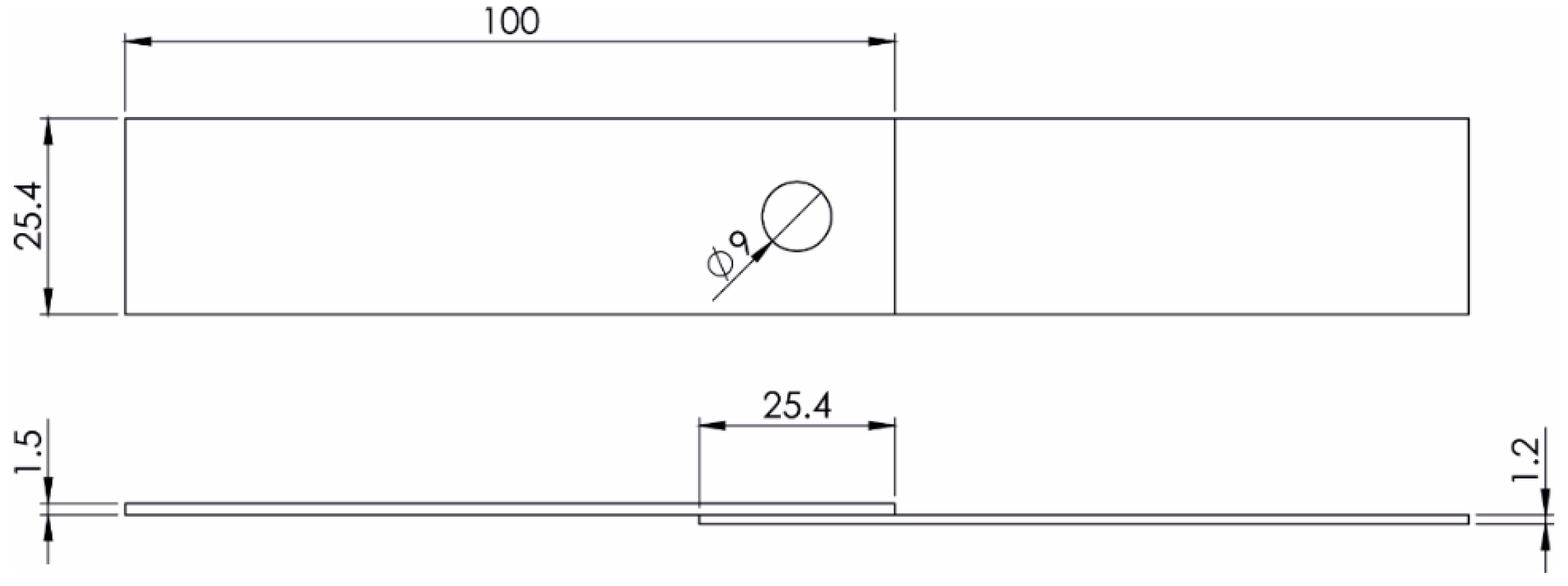
Quasi-static lap shear tests were performed to assess the mechanical performance and further characterize the produced welds. Coupon specimens with 100 × 25.4 mm and an overlap length of 25.4 mm were used in accordance with the AWS D17.2 [32]. An overview of the configuration is presented in Figure 3. The quasi-static lap shear tests were performed at room temperature, with a crosshead speed of 2 mm/min in a universal testing machine (Zwick/Roell Group, Ulm, Germany) equipped with a 100 kN load cell. Five replicates were analyzed to calculate the average ultimate lap shear force (ULSF) of the samples. The steel surface after testing was examined by SEM. An FEI Inspect S50 microscope (FEI, Hillsboro, OR, USA) equipped with an EDAX energy-dispersive spectroscopy (EDS) detector was used for the microstructural characterization.
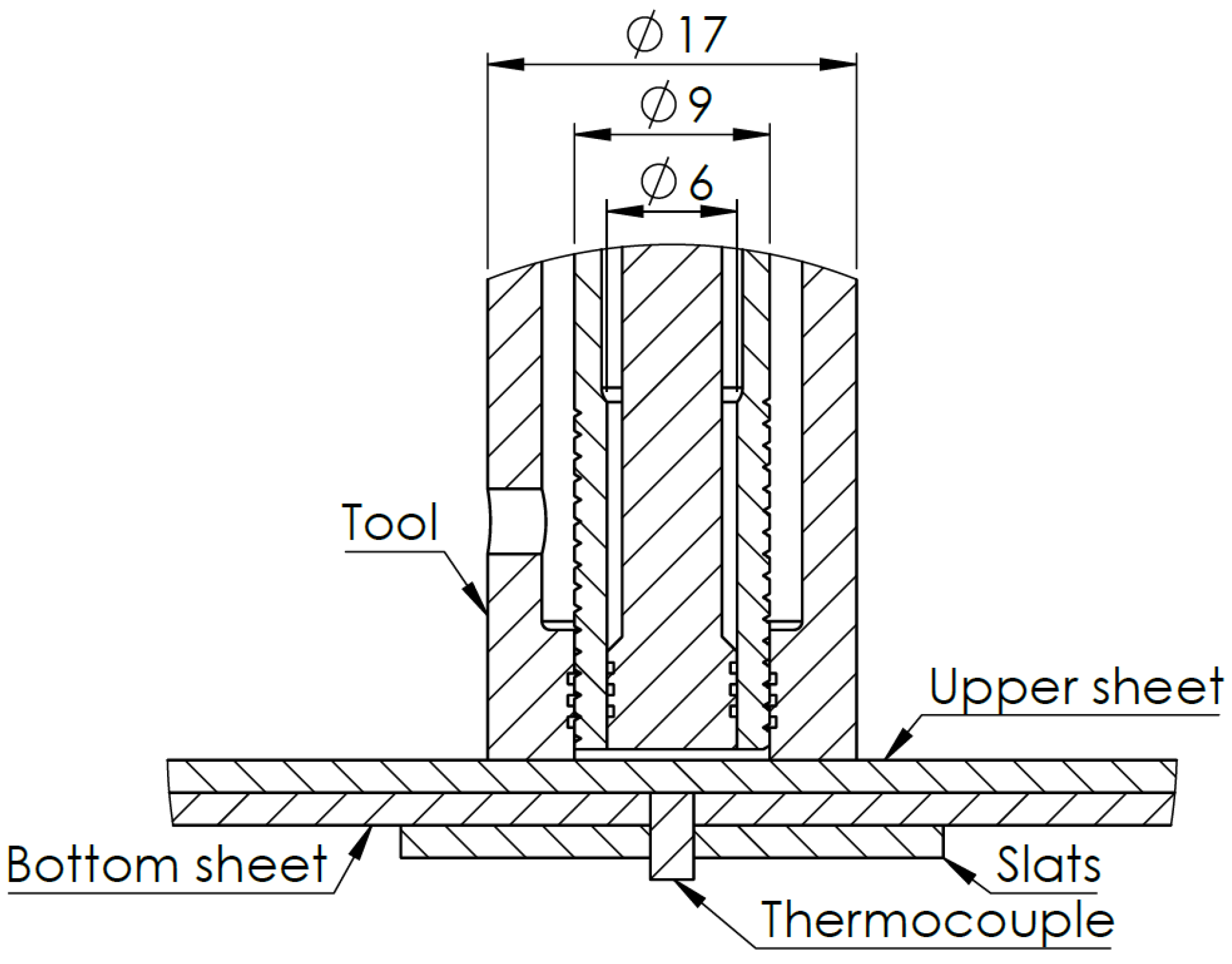
The temperature development was monitored throughout the entire welding cycle. Accurately measuring the temperature during refill FSSW is challenging as the maximum temperatures are reached predominantly at the volumetric center of the spot, a region with challenging access due to tool rotation and motion. Therefore, the present study monitored the temperature development using a K-type thermocouple positioned underneath the welding spot area, at the interface between the upper and bottom sheets. A hole was drilled in the bottom sheet, and the thermocouple was securely installed in this region, just tenths of a millimeter away from the spot center. To ensure optimal thermal contact and measurement accuracy, the thermocouple was welded in place and the surrounding contact area was fully filled with thermal paste. This setup provided both mechanical stability and efficient heat transfer. To prevent the thermocouple from being destroyed under the clamping pressure of the equipment, two supporting slats were placed beside it, leaving a gap for the thermocouple to be safely placed, as shown in Figure 4.

2.3. Hardness and Microstructure Characterization

Hardness tests were performed to investigate the effects of the thermomechanical welding cycle on the local mechanical properties of the material and to identify the transition regions between the welding zones. Plaine et al. [11] observed that the temperature reached during the refill FSSW process for dissimilar materials, and a tool plunge focused exclusively on the upper sheet, is normally not enough to promote significant microstructural changes in the bottom plate. A similar behavior was observed in preliminary investigations by the authors and, therefore, the present study will solely focus on the changes in the upper Al plate. Vickers hardness measurements were performed in accordance with the ASTM E384 [33] standard at the mid-thickness of the aluminum sheet in the transverse section and on the upper Al surface. The transverse profile covered a 16 mm line across the weld, while the surface mapping spanned an area of 15 × 11 mm, encompassing the entire welded spot. These measurements were carried out using a load of 300 gf (HV0.3) with a dwell time of 15 s and a minimum spacing of 0.5 mm between two adjacent indentations.
The interface and surface of the AA6016-T4 weld were prepared for microstructural characterization using a standard metallographic procedure involving flat grinding and mechanical polishing with diamond suspensions. The polished interface was subsequently etched with Keller’s reagent (2.5 mL HF (40%), 1.5 mL HCl, 1.0 mL HNO3, and 95 mL H2O) to assess the interfacial microstructure. In turn, the polished surface of the AA6016-T4 weld was electrochemically etched with Barker’s solution (5 mL of HBF4 in 200 mL H2O) at an operating voltage of 20 V for 90 s, thereby revealing the grain structure of the welding zones. The resulting microstructure was examined by LOM under polarized light. The average grain size for each region was determined using the intercept method following the ASTM E112 standard [34]. Polished samples were also analyzed via SEM and energy dispersive spectroscopy (EDS) using a Magellan 400 L (FEI, Hillsboro, OR, USA) with an acceleration voltage of 25 kV.

2.4. Potentiodynamic Anodic Polarizaton Tests

Potentiodynamic polarization tests evaluated the localized corrosion resistance of the welding zones. A neutral, naturally aerated solution containing 0.01 M sodium chloride (NaCl) and 0.1 M sodium sulfate (Na2SO4) was used at 25 °C. This electrolyte composition had been previously established in an earlier study by our research group [20]. Na2SO4 was added to improve the identification of pitting potential (Epit) during the polarization tests of the aluminum alloy. Lee et al. [35] observed that sulfate (SO42−) ions retard the breakdown of the aluminum oxide passive film by chlorides (Cl), therefore increasing the passive region in the polarization curve and facilitating the visualization of Epit. A three-electrode electrochemical cell with a platinum sheet (area of 5 cm2) counter electrode and silver/silver chloride—Ag/AgCl—(in saturated KCl solution) reference electrode was used for the potentiodynamic polarization tests.
The working electrodes—consisting of samples from different welding regions, were positioned at the electrochemical cell, leaving a 0.215 cm2 circular area of the aluminum alloy surface exposed to the test solution. Samples were carefully wet sanded with a 600-grit silicon carbide (SiC) sandpaper, followed by distilled water washing and air drying before polarization measurements. After immersion in the solution, the samples were left in an open circuit for 30 min to ensure that a steady potential would be reached, and the resulting potential value was regarded as the open circuit potential (Eoc).
The potentiodynamic polarization tests started at 300 mV below Eoc and ended immediately after the Epit was reached to prevent a deeper corrosive attack. A scan rate of 1 mV/s was applied. The mean values of corrosion potential (Ecorr) and Epit were obtained from five independent measurements, along with the standard deviation. After the corrosion tests, each welding region was analyzed by SEM to identify the surface corrosion morphology.

3. Results and Discussion

3.1. Interface Characterization

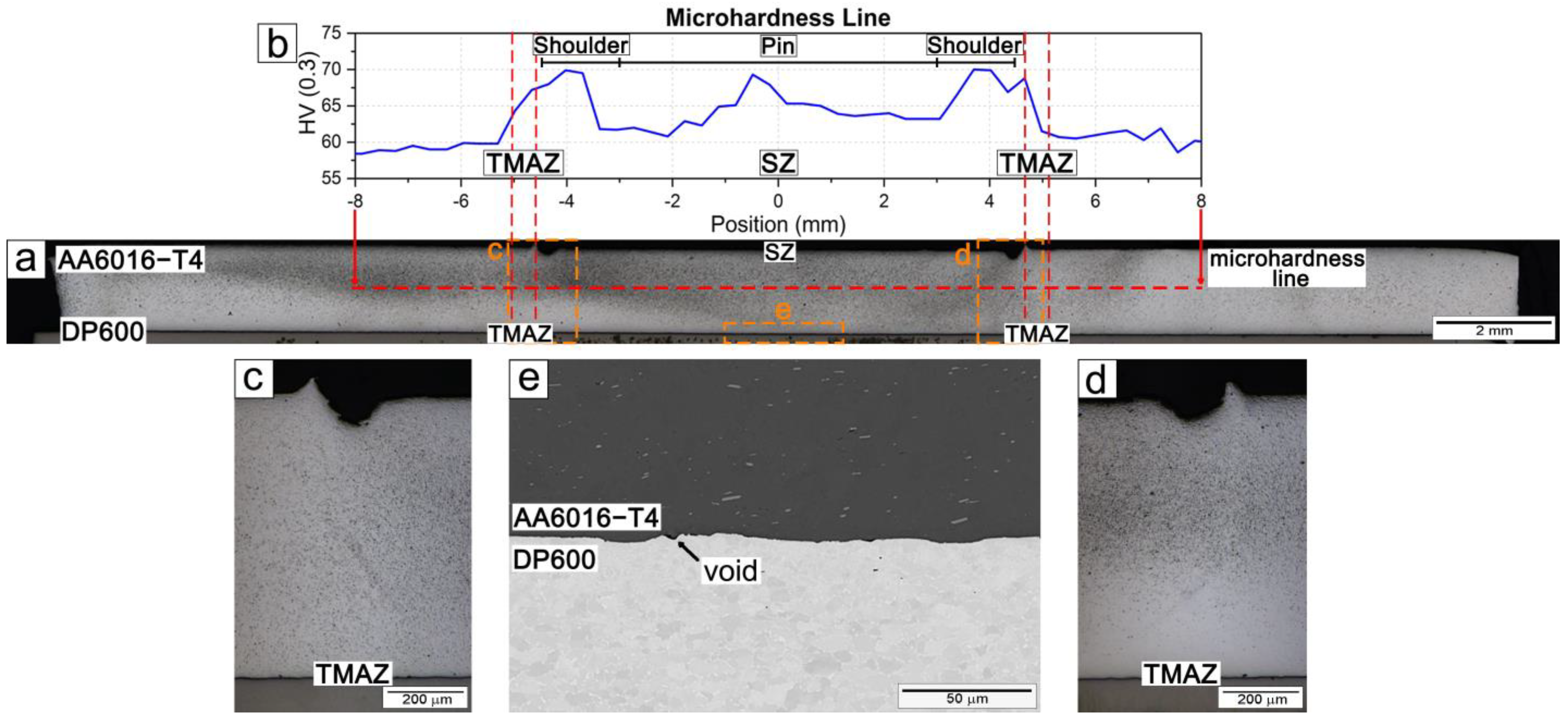
Figure 5a shows the cross-section of the AA6016-T4/DP600 dissimilar joint produced by RFSSW, where the AA6016-T4 aluminum alloy is joined to the DP600 steel sheet. The Al/steel interface appears relatively uniform, with no evidence of macroscopic plastic deformation in the steel substrate, as the tool does not penetrate into the bottom sheet. Nevertheless, the aluminum and steel are continuously bonded due to the high pressure and temperature generated by the RFSSW process.
Figure 5b presents the hardness mapping across the mid-thickness of the AA6016-T4 sheet (dashed red line). The hardness distribution is symmetrical around the tool axis and exhibits an intermediate hardness of approximately 65 HV0.3 in the central pin region. Hardness increases towards the shoulder area, reaching values close to 70 HV0.3, before gradually decreasing to stabilize at the base material level (around 60 HV0.3). Figure 5c,d show higher magnification images of the thermo-mechanically affected zone (TMAZ), confirming the absence of typical defects such as wormholes or cracks.
Figure 5e shows the Al/steel interface, revealing a metallurgical bond with only a few isolated voids that do not compromise the lap shear mechanical performance. It is well established that when the sleeve plunging depth is lower than the aluminum sheet thickness, the process behaves similarly to friction stir brazing [36]. Under these conditions, the aluminum and steel sheets bond mainly through interdiffusion at the interface, leading to the formation of a serrated Fe–Al intermetallic compound (IMC) layer. The development of this layer is governed by the diffusion of Fe and Al atoms, with its thickness being highly sensitive to both the peak temperature reached and the applied dwell time. Dong et al. [19] reported the formation of an approximately 0.68 μm thick IMC layer in dissimilar Al/steel RFSSW joints with a dwell time of 2 s. In this study, at a dwell time of 1 s, no IMC layer was detectable by SEM. Nevertheless, it must be emphasized that SEM resolution may not reveal nanometric intermetallic layers. High-resolution analyses such as TEM or STEM-EDS are necessary to confirm their presence or absence. Future work should address this limitation.
Figure 6a evaluates the mechanical performance through a representative force–displacement curve of a refill FSSW dissimilar AA6016-T4/DP600 joint obtained from quasi-static lap shear testing. During the lap shear test, the force–displacement curve exhibited a typical behavior with an initial elastic region followed by pronounced plastic deformation before failure. After a linear rise in load, the curve entered a plastic regime in which the softer aluminum (AA6016-T4) sheet around the weld yielded and deformed significantly, accommodating further displacement at near-maximum load. This plastic plateau indicates that the joint sustained load through ductile deformation (primarily in the aluminum sheet and the weld zone) up to the peak force. Ultimately, the curve dropped as the joint failed, corresponding to crack propagation and final fracture. The plastic regime is associated with bending and stretching of the aluminum around the weld and any mechanical interlocks present, which contributes to energy absorption before failure. Such behavior is desirable as it delays fracture; a more brittle, interfacial failure would show a more abrupt load drop with lower displacement [37]. The welded specimens exhibited an ultimate lap shear force of 4.6 ± 0.25 kN and a displacement at failure of 1.7 ± 0.2 mm. These results confirm that the welding parameters were properly selected, as the joints satisfied the requirements for aerospace applications by surpassing the minimum ULSF specified in AWS D17.2M [32] (3.6 kN) by approximately 25%. Moreover, the performance values are consistent with those reported in the literature for similar Al sheet thicknesses in dissimilar combinations, such as AA6181-T4/Ti-6Al-4V [14], AA6022-T4/DP600 [38], as well as for dissimilar AA7075-T6 welds [39].
Figure 6b shows the fracture surface after the lap shear testing. The image corresponds to a top view of the lower steel sheet, and the area fractions were estimated by image analysis of SEM micrographs. The failure mode observed was a mixed “pull-out” type: the weld did not fail by pure interface delamination at the peak load; instead, part of the aluminum nugget was pulled out from the steel sheet, involving both interfacial and through-thickness fracture of the aluminum. This mixed failure mode is consistent with higher joint ductility and strength compared to a purely interfacial fracture. The fracture surface analysis confirms a mixed ductile–brittle fracture mode for these dissimilar Al/steel welds. The first (Figure 6c) exhibits ductile fracture morphology characterized by elongated parabolic dimples morphology and corresponding to 70–80% of the analyzed area, which is characteristic of ductile shear failure under lap shear loading. Such dimples result from microvoid nucleation, growth, and coalescence during plastic deformation, and their parabolic/elongated morphology indicates a significant shear stress component during fracture. Between these dimples, however, it can be observed smoother facets—areas that appear cleavage plane-like—especially in a certain zone of the fracture surface. These facets indicate that locally the crack propagated in a brittle mode (cleavage or quasi-cleavage) with minimal plastic deformation. Such mixed-mode failure in dissimilar aluminum/steel friction stir welds has also been reported by other researchers [37,40]. Chitturi et al. [40] observed that lap welds between AA5052 and steel fractured with a combination of dimples and quasi-cleavage facets at different zones. Zhang et al. [37] noted a clear brittle-to-ductile transition region in Al/steel spot weld fractures, with the crack often initiating in a brittle manner and then propagating through a ductile shear-tear area. The second one (Figure 6d) displays brittle fracture features with cleavage planes with 20—30% of the analyzed area. This zone is associated with the material flow and local metallurgical condition at the Al/steel interface. According to Dong et al. [19], a vortex forms at this stage, with material flowing from the center to the edge. This is driven by the relative counter-rotation of the probe and the shoulder. The authors reported that in these regions the Fe–Al intermetallic layer was absent, as the vortex-like material flow displaced the IMC layer toward the periphery, weakening the metallurgical bond and promoting brittle and intergranular fracture. In contrast, in the central pin region and the outermost areas, where the material was not significantly affected by this flow, the metallurgical bonding was preserved, leading to a predominantly ductile fracture mode.
Although the peak temperatures reached during refill FSSW are considerably lower than those observed in conventional fusion welding, de Carvalho et al. [9] demonstrated that the combined effects of plastic deformation and frictional heating in refill FSSW strongly influence the microstructure, as well as the mechanical and chemical properties of the joint. Figure 7 presents three representative temperature–time curves obtained during the analyzed welding cycles, indicating a resulting welding cycle of 5.0 ± 0.5 s for the selected parameters. A steep increase in temperature is observed within the first 3 s, reaching peak values of approximately 427 ± 33 °C. With a dwell time of 1 s (i.e., the period during which the tool remains rotating within the sheets, as depicted in Figure 1b, the cooling stage begins immediately after tool retraction (Figure 1c). During this stage, the temperature decreases from approximately 427 °C to 100 °C within about 60 s. Similar temperatures were reported by Shen et al. [38] for RFSSW in dissimilar Al/steel joints.
Although this cooling cycle appears longer than those reported in previous studies [9], it must be emphasized that, as described in Section 2.2, the thermocouple was placed directly at the Al/steel interface, rather than below the bottom steel sheet as is typically done in the literature. However, it should be noted that this single thermocouple measurement reflects only the local thermal history near the Al/steel interface. Given the complex heat flow in RFSSW, significant temperature gradients may exist between the SZ, TMAZ, and HAZ. As such, while the measured peak temperature supports the interpretation of grain refinement and precipitate evolution in the SZ, microstructural changes in surrounding zones must be interpreted with caution due to potential thermal variation. Consequently, the thermal data reported here more accurately reflects the region closest to the weld center, where higher temperatures are expected. Higher peak values can therefore be anticipated at the volumetric core of the weld. Notably, the maximum temperature at the interface was around 420 °C, indicating insufficient energy input to plasticize the steel. This observation confirms the suitability of shoulder plunge depth of 1.3 mm, which ensures adequate joint formation and prevents excessive tool wear by avoiding direct contact between the tool and the steel substrate.
As a precipitation-hardenable Al alloy, the AA6016 alloy has its mechanical properties mainly determined by the volumetric fraction, size and distribution of strengthening precipitates, which will be affected by the welding cycle [8,41,42]. Dolan and Robison [43] observed that the 6XXX Al alloys have a high quench sensitivity and a critical temperature range of 220 °C and 440 °C. Therefore, based on the temperatures presented in Figure 7, microstructural changes are expected in the upper material (Al sheet), mostly in the grain size distribution and secondary particle features, which certainly influence the corrosion behavior of the welded sheet.

3.2. Surface Characterization

3.2.1. Microstructure and Hardness Characterization

Figure 8a shows the etched surface of the welded AA6016-T4 alloy, together with a schematic representation of the diameters of the three tool components and their relative position to the spot area. The microstructure resulting from the refill FSSW cycle can be divided into four distinct regions, which are typical for friction-based processes applied to aluminum alloys: BM; HAZ; TMAZ; and stir zone (SZ) [44]. The BM remains unaffected by the welding cycle, retaining its original condition without undergoing plastic deformation or microstructural modification. The HAZ is exclusively influenced by the thermal cycle and does not undergo plastic deformation; however, some grain coarsening relative to the BM can occur, as is often reported in precipitation-hardenable 6xxx series alloys. The TMAZ, which is located outside the shoulder’s outer radius and usually has highly deformed and elongated grains. This reflects the combined effects of straining and moderate thermal exposure [6]. In contrast, the SZ experiences the most intense thermo-mechanical conditions, with severe plastic deformation and elevated temperatures leading to dynamic recrystallization and the formation of refined equiaxed grains [45,46,47]. Microstructural refinement in the SZ has a significant impact on the mechanical and electrochemical response of the joint. Due to practical constraints, it was impossible to clearly define the transitions between BM and HAZ, even after calculating the average grain size. Therefore, the HAZ was excluded from the analyses below.
Figure 8b–d presents higher-magnification views of the BM, TMAZ, and SZ regions, respectively. The BM (Figure 8b) exhibits equiaxed, randomly oriented grains with an average size of 37 ± 17 µm. In the TMAZ (Figure 8c), the grains exhibit a distorted structure and are oriented toward the shoulder rotation due to the deformation process occurring at moderate temperatures in this region. In contrast, the SZ (Figure 8d), clearly shows a homogeneous microstructure with equiaxed and refined grains resulting from the dynamic recrystallization process due to the high temperature and shear strain rate reached during the welding process. Moreover, note that the grains in the SZ are smaller (average grain size of 19 ± 8 µm) than those in the BM.
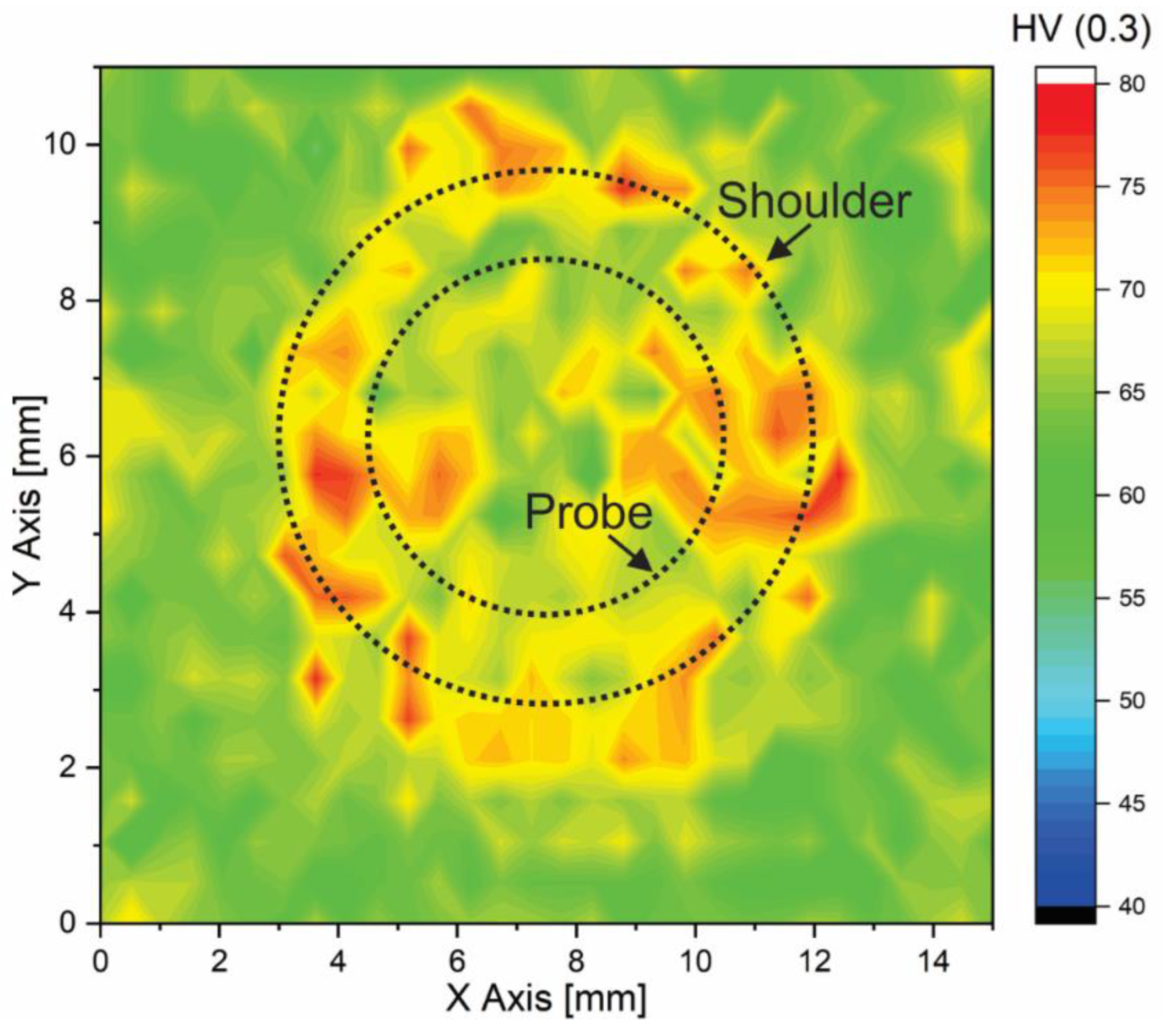
Figure 9 shows the hardness distribution of the AA6016-T4 alloy at the top surface of the welded region. Figure 9 also outlines the external diameters of the shoulder and probe, along with their relative positions to the spot area. The map reveals that the BM exhibits an average hardness of approximately 65 HV0.3, which corresponds to the lowest values observed across the analyzed region. In contrast, the TMAZ displays increased hardness, reaching around 80 HV0.3. This enhancement can be attributed to the severe plastic deformation induced by the rotation and plunging action of the shoulder, which produced the elongated and distorted grains shown in Figure 8c.
The SZ exhibits intermediate hardness values, which are slightly higher than those of the BM, but lower than those of the TMAZ. This reflects the conflicting effects of grain refinement through dynamic recrystallisation, which increases hardness, and possible overaging or partial dissolution of strengthening precipitates, which can cause softening [48]. It is also notable that the hardness map indicates that a clear distinction between the BM and the HAZ could not be made, which suggests that the HAZ is very narrow. This is in accordance with what is reported in the literature for a similar process applied to the same alloy [41].
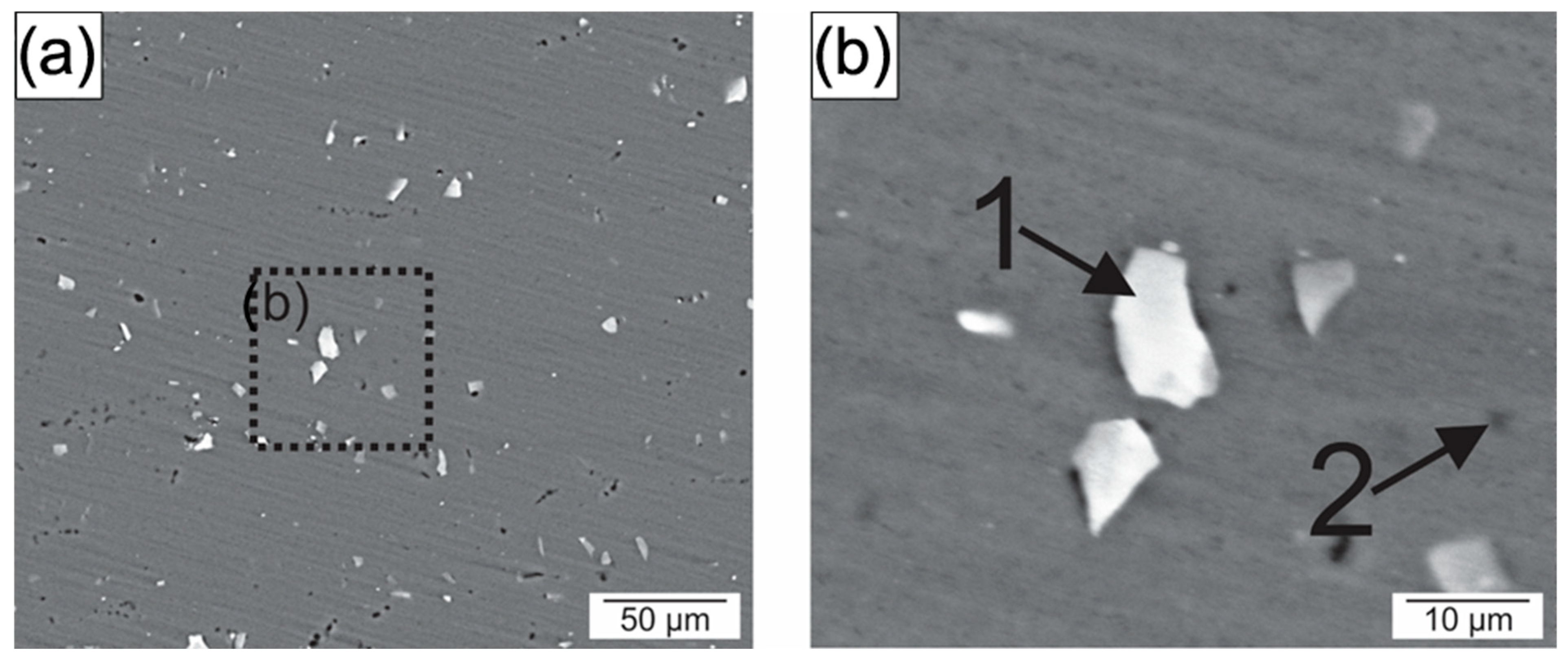
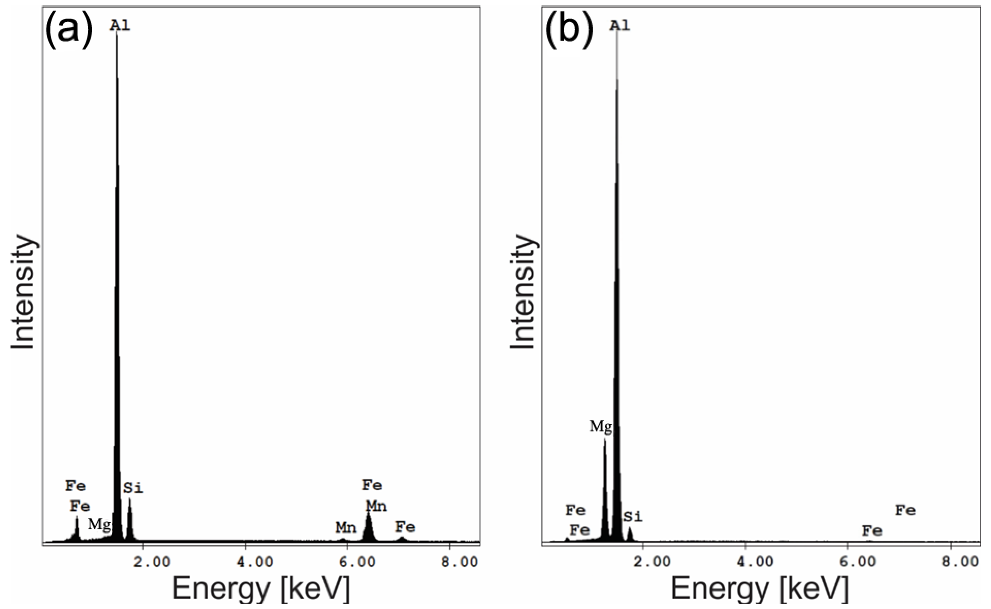
Figure 10 shows SEM images of the BM, here two main types of precipitates can be distinguished, as indicated by the arrows. Complementary EDS analyses enabled the chemical identification and characterization of these particles, whose morphologies are displayed in Figure 10b. These precipitates were the only secondary constituents observed uniformly distributed throughout the aluminum matrix. The EDS spectra, presented in Figure 11 and summarized in Table 3, reveal that the light-contrast particles are enriched in Fe, Si, Mn, and can thus be assigned to Al(Fe, Mn)Si particles, with residual Mg arising from the interaction volume of the EDS signal with the surrounding matrix. In contrast, the dark-contrast precipitates are rich in Si and Mg, corresponding to Mg2Si precipitates. Similar findings regarding the coexistence of these two phases in 6XXX alloys have been reported in the literature [49]. In the base material, the volumetric fraction of particles measured from Figure 10a was 1.89 ± 0.20%.
The presence of the light-colored secondary particles can be attributed to the alloy’s chemical composition and the applied heat treatment. This alloy contains 0.17 wt.% iron (Fe), whereas the maximum solubility of Fe in Al alloys is only 0.05 wt.% at 655 °C. Consequently, such Fe-rich particles are expected to form during solidification and are difficult to dissolve during subsequent heat treatments due to their high thermodynamic stability. In contrast, the dark precipitates (Mg2Si) typically form during processing.
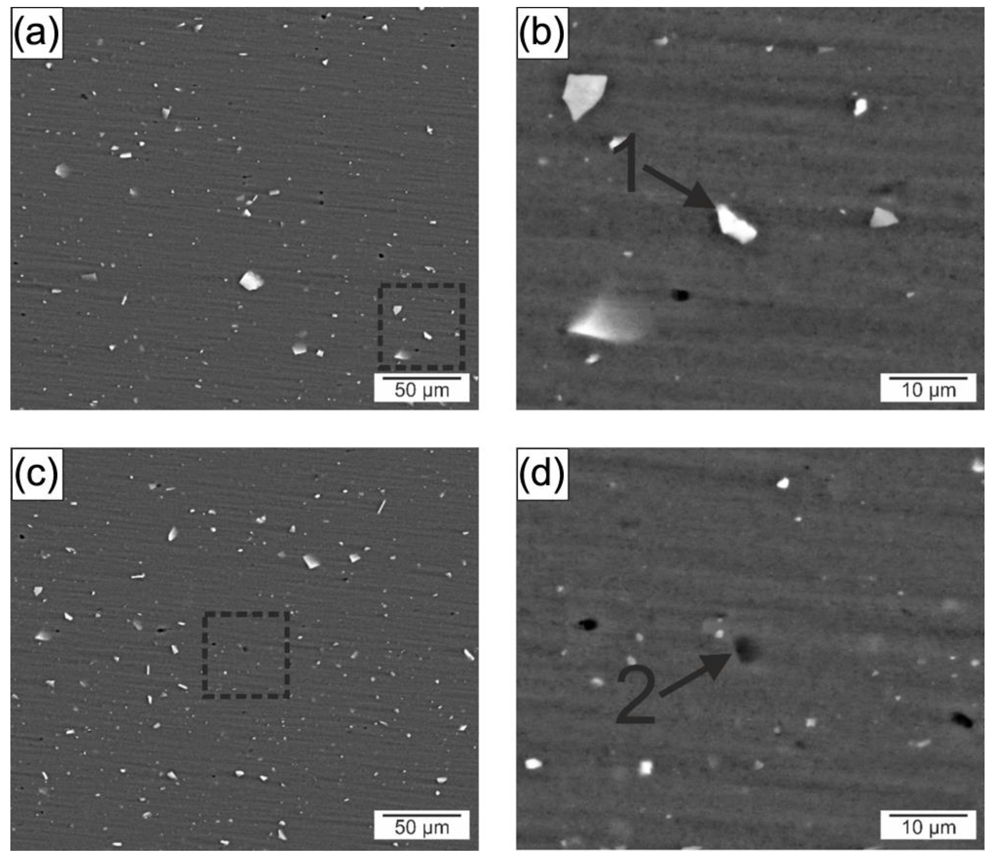
A similar analysis was performed in the SZ, the results of which are shown in Figure 12. These reveal a reduction in residual porosity in this region, resulting from the compressive forces applied by the tool during welding. The same types of precipitates observed in the BM were also identified in the SZ, as reported in Table 4. However, the Al(Fe, Mn)Si particles appear to have a smaller average sizes, which is consistent with the fragmentation of larger particles occurring during severe plastic deformation at elevated temperatures. Yang et al. [50], investigating 2xxx series aluminum alloys subjected to friction stir welding (FSW), similarly reported a reduction in precipitate size within the SZ, attributing this effect to the fragmentation of larger BM particles. These findings corroborate the present results.
On the other hand, the Mg2Si precipitates that form in SZ seem to be slightly larger than those in BM. Similar trends have been documented by Donatus et al. [51] and Gallais et al. [48] in 6xxx series friction stir welded alloys, where Mg2Si coarsening was observed particularly in the HAZ. This phenomenon arises from the thermal cycle during welding, which can reach temperatures near 450 °C. These temperatures promote Mg2Si coalescence and loss of coherency, thereby enhancing precipitation hardening [48].
Additionally, the volumetric fraction of particles in the SZ, as quantified from Figure 12a,c, was 1.74 ± 0.21%. This value indicates that the overall precipitate density remained largely unchanged between the BM and SZ.
The correlation between thermal profile, hardness distribution, and mechanical performance can be understood as a direct consequence of the thermo-mechanical history imposed by the RFSSW process. The process, carried out with a 1 s dwell time, successfully promoted joint formation between aluminum and steel sheets, achieving lap shear strength values above the threshold required by aerospace standards (Figure 6). Fractographic analysis revealed a mixed fracture mode: brittle features were observed beneath the shoulder region, while the central and outer regions exhibited ductile characteristics, indicating localized differences in microstructural response. Temperature measurements indicated peak values near 440 °C at the AA6016-T4/DP600 interface, which likely contributed to the coarsening of Mg2Si precipitates. At the same time, Al(Fe, Mn)Si particles that are insoluble under these thermal conditions, appeared slightly fragmented and more uniformly distributed as a result of the thermo-mechanical processing (Figure 12). In addition, dynamic recrystallization led to grain refinement in the stir zone (Figure 8), contributing to the moderate hardness increase observed in the SZ and TMAZ.

3.2.2. Corrosion Characterization

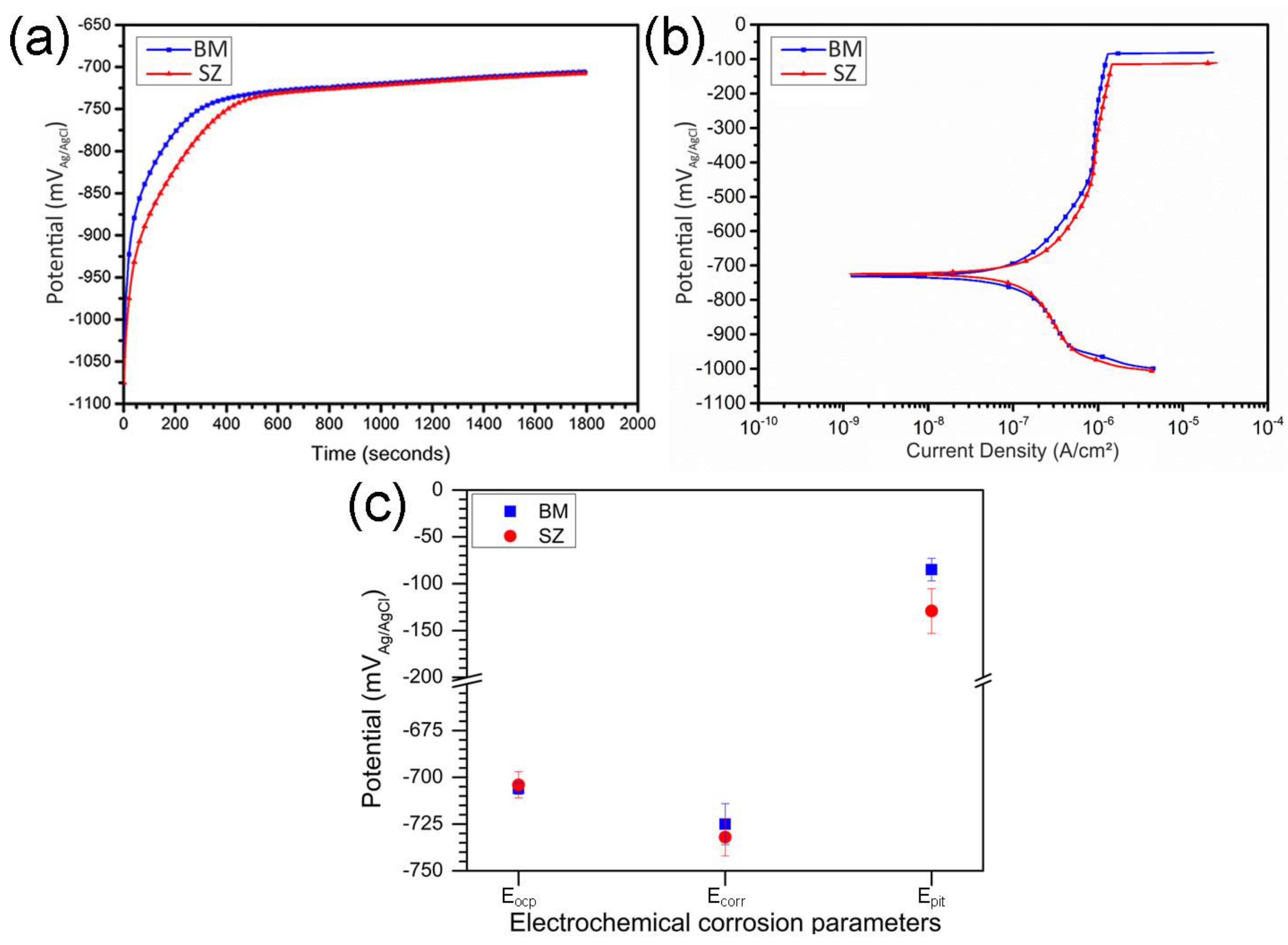
Since the aluminum surface is the region directly exposed to aggressive environments in service, the corrosion tests were deliberately focused on this surface. This approach provides essential insights into the durability of dissimilar Al/steel joints by isolating the intrinsic corrosion behavior of aluminum. Microstructural observations (Figure 8) and hardness mapping (Figure 9) revealed that the HAZ and TMAZ were extremely narrow, preventing a reliable and independent assessment of their corrosion response. For this reason, the electrochemical evaluation was restricted to the BM and SZ. Figure 13 presents the open-circuit potential and potentiodynamic polarization curves for both regions and the electrochemical parameters extracted from polarization curves are summarized in Figure 13c and Table 5. Figure 13a shows a rapid increase in the potential up to 600 s with an open circuit potential (Eocp) stabilization around 700 mVAg/AgCl after 3600 s, indicating that the steady state has been reached for both conditions.
The corrosive behaviors between the BM and SZ regions were similar during the potentiodynamic polarization curve (Figure 13b). The Ecorr were statistically equivalent, measured at −725 ± 12 mVAg/AgCl for the BM and −732 ± 10 mVAg/AgCl for the SZ. Although the refill FSSW process promoted microstructural changes in the SZ microstructure, these changes were not sufficient to affect the kinetics of the anodic and cathodic reactions occurring on the surface [52]. A difference of approximately 25 mVAg/AgCl between Ecorr and Eocp was observed, which can be attributed to partial reduction in metallic ions within the passive film during cathodic polarization, thereby shifting Ecorr toward more negative values [53]. Both the BM and the SZ exhibited very low passive current densities (approximately 10−6 A/cm2), which is consistent with the presence of an effective passive film. These values align with previously reported data for aluminum alloys joined by solid-state welding techniques [10,20].
However, the Epit differ for BM and SZ regions. These differences may be attributed to the type, size and distribution of precipitates. The Al(Fe, Mn)Si particle behaves cathodically with respect to the matrix, promoting localized dissolution of the surrounding aluminum [54], while Mg2Si exhibits anodic behavior and preferentially dissolves during chloride exposure due to the formation of a galvanic cell [55]. Precipitate size and density are therefore critical parameters. A smaller cathode-to-anode area ratio weakens galvanic interactions, whereas high precipitate density intensifies them, thereby accelerating localized dissolution. Jiang et al. [56], studying an Al-Si alloy subjected to severe plastic deformation, reported that refining precipitate size diminished galvanic intensity, improving resistance to localized attack. In the present welds, the Epit of the BM was −85 ± 12 mVAg/AgCl, compared with −129 ± 39 mVAg/AgCl for the SZ. Although the values may appear statistically similar, the SZ exhibited a slightly lower average value compared to the BM. Since both regions contained Al(Fe, Mn)Si and Mg2Si particles, the observed difference is attributed to variations in size and volume fraction. Vacchi et al. [20], evaluating the corrosion resistance of AA6181-T4 aluminum during refill FSSW welding of an Al-Ti joint, observed that welding promoted a breakdown and reduction in the size of the Al(Fe, Mn)Si precipitates. This reduction caused an improvement in the SZ corrosion resistance compared to the BM. In the present study, however, the shorter dwell time (1 s vs. 3 s) and lower rotational speed (1000 rpm vs. 2500 rpm) limited the refinement of precipitates, which was insufficient to improve SZ corrosion resistance. Instead, the reduction in Epit was likely accounted for by the slight coarsening of Mg2Si precipitates due to thermal exposure (Figure 12), as these particles act as preferential nucleation sites for pitting. These findings are consistent with those of Gharavi et al. [28], who reported lower Epit values in the SZ of friction stir welded AA6061 lap joints than in the BM. They attributed this behavior to the higher density of precipitates formed during welding. Additionally, the difference in standard deviations between the BM and SZ is also related to these precipitates, whose size and density may vary slightly from one test to another, leading to greater data dispersion, particularly in the SZ.
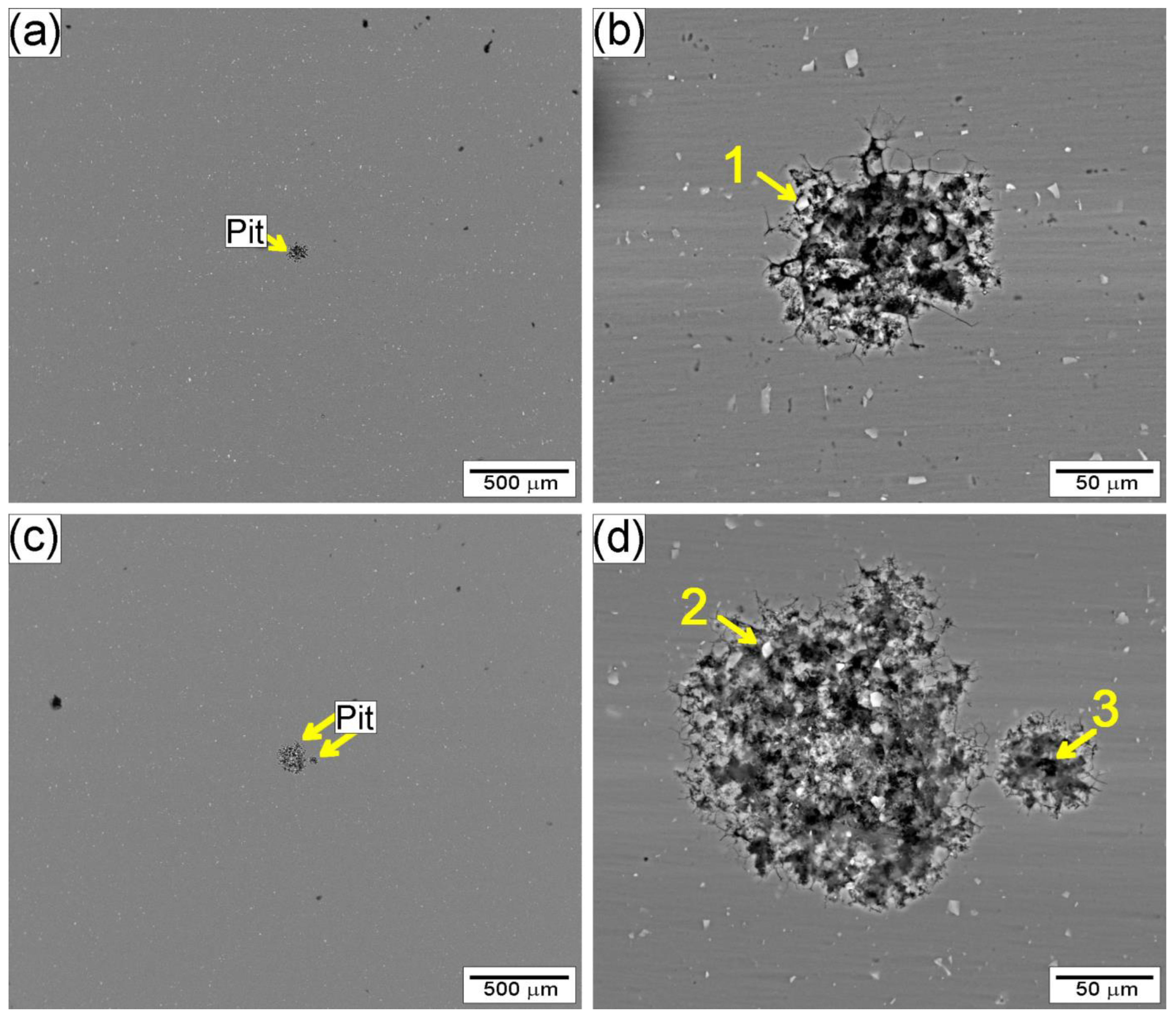
Figure 14 presents the surface morphologies of the BM (a and b) and SZ (c and d) after potentiodynamic polarization testing. From Figure 14a,c, the presence of pits can be clearly observed on the surfaces of both the BM and the SZ. Pitting in aluminum alloys may occur within the aluminum matrix, along grain boundaries, in regions with a high dislocation density, or adjacent to precipitates and even through the dissolution of the precipitates themselves. Although regions with high dislocation density exhibit elevated energy, the recrystallization process observed in Figure 8d reduced the presence of such areas in the SZ. In comparison, the widespread distribution of second-phase particles throughout the material promotes pit nucleation driven by galvanic mechanisms, which occurs preferentially over nucleation associated with grain boundaries or directly within the aluminum matrix. Figure 14 shows that pits predominantly form adjacent to precipitates, as confirmed by EDS analysis (Table 6). The pit areas are significantly larger than the precipitates themselves, a fact likely associated with the addition of Na2SO4 to the test solution. This inorganic compound expands the passive region but accelerates the dissolution of the aluminum matrix once pit nucleation has occurred [35]. However, the pits on the BM surface were smaller and shallower compared with those in the SZ, indicating a lower severity of localized corrosion attack. This is consistent with the higher Epit value measured for the BM. It is also noteworthy that a second pitting mechanism associated with the Mg2Si precipitates (Table 6) was identified in the SZ. These particles acted as preferential nucleation sites for pit initiation compared to the matrix, thereby contributing to the reduction in Epit observed in the SZ. Similar behavior has been reported for Al–Mg–Si alloys, where the anodic dissolution of Mg2Si facilitates localized breakdown of the passive film and accelerates pit propagation [26,56].
Figure 15 presents the proposed corrosion mechanism models for the BM and the SZ. The primary secondary phases identified in both regions are Al(Fe, Mn)Si and Mg2Si particles; however, their size and distribution differ. In the BM, the Al(Fe, Mn)Si particles are significantly larger than the Mg2Si precipitate (Figure 10). In contrast, within the SZ, the refill FSSW process induces a slight refinement of the Al(Fe, Mn)Si particles, while the thermal cycle promotes coarsening of Mg2Si precipitates. After immersion in the test solution (0.01 M NaCl + 0.1 M Na2SO4), galvanic cells form between the precipitates and the aluminum matrix. In the BM, pit nucleation occurs preferentially adjacent to the Al(Fe, Mn)Si precipitates due to their larger size and higher volume fraction compared to Mg2Si. Conversely, in the SZ, the increased size and volume fraction of Mg2Si results in both types of precipitates acting as pit nucleation sites. The surrounding matrix dissolves around Al(Fe, Mn)Si, whereas Mg2Si exhibits intrinsic anodic behavior and undergoes preferential dissolution. Zeng et al. [26] have described the corrosion mechanism of Mg2Si in detail, showing that selective dissolution of Mg enriches the precipitate in Si (Table 6). This compositional shift alters its electrochemical character from cathodic to anodic. With prolonged immersion, the Al matrix undergoes accelerated localized attack, preferentially dissolving around Si-enriched Mg2Si particles.

4. Conclusions

The present study investigated the effects of the refill FSSW process on the microstructure, mechanical performance, and localized corrosion resistance of the aluminum surface in dissimilar AA6016-T4/DP600 joints. The main conclusions are as follows:
  • Defect-free welds were achieved under the selected parameters, reaching an ultimate lap shear force of 4.6 ± 0.25 kN. The joints exhibited a mixed fracture mode, predominantly ductile, with limited brittle regions near the shoulder/pin interface.
  • The aluminum stir zone (SZ) displayed refined equiaxed grains and increased hardness relative to the base metal, reflecting the combined influence of plastic deformation and dynamic recrystallization. Fe-rich precipitates were fragmented, whereas Mg2Si precipitates showed slight coarsening under the welding thermal cycle.
  • Electrochemical tests indicated similar corrosion potentials (Ecorr) for the SZ and base metal, but a lower pitting potential (Epit) in the SZ. Pit initiation occurred primarily near Al(Fe, Mn)Si and coarsened Mg2Si precipitates, explaining the modest reduction in localized corrosion resistance.
  • The Al/steel interface exhibited a continuous metallurgical bond with minimal voids. No intermetallic layer was detected by SEM, suggesting that if present, it is of nanometric thickness and requires high-resolution characterization.
Overall, this study broadens the understanding of the mechanical and localized corrosion behavior of the aluminum surface in RFSSW dissimilar joints. The results highlight both the potential and the challenges of this technique for lightweight aluminum–steel applications. The analyses were limited to the aluminum surface and based mainly on SEM and potentiodynamic polarization. Future investigations incorporating alloy design strategies aimed at refining Fe-rich intermetallics, along with high-resolution TEM/STEM-EDS, electrochemical impedance spectroscopy (EIS), and galvanic testing, are recommended to further elucidate interfacial reactions and long-term durability. From a practical perspective, the findings suggest that precise control of dwell time and rotational speed is critical to balance heat input: minimizing precipitate coarsening and local softening, while still ensuring adequate material flow and metallurgical bonding. Optimizing these parameters can improve both corrosion resistance and mechanical performance in dissimilar AA6016-T4/DP600 joints produced by RFSSW.

Author Contributions

Conceptualization: W.S.d.C., G.d.S.V. and C.A.D.R.; methodology: W.S.d.C., G.d.S.V., U.F.H.S., D.C.C.M. and C.A.D.R.; validation, W.S.d.C., G.d.S.V., U.F.H.S., D.C.C.M. and C.A.D.R.; formal analysis, W.S.d.C., G.d.S.V., U.F.H.S., D.C.C.M. and C.A.D.R.; investigation, W.S.d.C. and G.d.S.V.; resources, U.F.H.S., D.C.C.M., C.A.D.R. and R.d.S.; data curation, W.S.d.C., G.d.S.V. and R.d.S.; writing—original draft preparation, W.S.d.C., G.d.S.V. and C.A.D.R.; writing—review and editing, W.S.d.C., G.d.S.V., U.F.H.S., D.C.C.M., C.A.D.R. and R.d.S.; visualization, W.S.d.C. and G.d.S.V.; project administration, U.F.H.S. and C.A.D.R.; funding acquisition, U.F.H.S., C.A.D.R. and R.d.S. All authors have read and agreed to the published version of the manuscript.

Funding

This study was financed in part by the Coordenação de Aperfeiçoamento de Pessoal de Nível Superior—Brasil (CAPES)—Finance Code 001. This work was also supported by the Brazilian research funding agency CNPq (grant no. 315903/2023-6) and by the Helmholtz Association of German Research Centers for their technical support.

Data Availability Statement

The original contributions presented in the study are included in the article. Further inquiries can be directed to the corresponding authors.

Acknowledgments

The authors gratefully acknowledge CAPES (Coordination for the Improvement of Higher Education Personnel), CNPq (National Council for Scientific and Technological Development and PPGCEM/UFSCar (Materials Science and Engineering Postgraduate Program at the Federal University of São Carlos).

Conflicts of Interest

The authors declare no conflicts of interest.

References

  1. Cheah, L.W. Cars on a Diet: The Material and Energy Impacts of Passenger Vehicle Weight Reduction in the US. PhD Thesis, Massachusetts Institute of Technology, Cambridge, MA, USA, 2010. [Google Scholar]
  2. Polmear, I.; St John, D.; Nie, J.F.; Qian, M. Light Alloys: Metallurgy of the Light Metals; Butterworth-Heinemann: Oxford, UK, 2017. [Google Scholar]
  3. Coelho, R.S.; Kostka, A.; dos Santos, J.F.; Pyzalla, A.R. EBSD technique visualization of material flow in aluminum to steel friction-stir dissimilar welding. Adv. Eng. Mater. 2008, 10, 1127–1133. [Google Scholar] [CrossRef]
  4. Lee, C.-Y.; Choi, D.H.; Yeon, Y.-M.; Jung, S.-B. Dissimilar friction stir spot welding of low carbon steel and Al-Mg alloy by formation of IMCs. Sci. Technol. Weld. Join. 2009, 14, 216–220. [Google Scholar] [CrossRef]
  5. Şık, A. Comparison between microstructure characteristics and joint performance of AZ31 magnesium alloy welded by TIG and friction stir welding (FSW) processes. Kov. Mater. 2013, 51, 197–203. [Google Scholar] [CrossRef]
  6. Zou, Y.; Li, W.; Shen, Z.; Su, Y.; Yang, X. Refill friction stir spot welding of aluminum alloys: State-of-the-art and Perspectives. Weld. World 2023, 67, 1853–1885. [Google Scholar] [CrossRef]
  7. Zhao, Y.Q.; Yang, H.K.; Andriia, A.; Lo, H.H.; Li, J.X. Refill friction stir spot welding (RFSSW): A review of processing, similar/dissimilar materials joining, mechanical properties and fracture mechanism. J. Iron Steel Res. Int. 2024, 31, 1825–1839. [Google Scholar] [CrossRef]
  8. Feng, X.S.; Li, S.B.; Tang, L.N.; Wang, H.M. Refill Friction Stir Spot Welding of Similar and Dissimilar Alloys: A Review. Acta Metall. Sin. (Engl. Lett.) 2020, 33, 30–42. [Google Scholar] [CrossRef]
  9. de Carvalho, W.S.; Vioreanu, M.C.; Lutz, M.R.A.; Cipriano, G.P.; Amancio-Filho, S.T. The influence of tool wear on the mechanical performance of AA6061-T6 refill friction stir spot welds. Materials 2021, 14, 7252. [Google Scholar] [CrossRef]
  10. Vacchi, G.S.; Silva, R.; Plaine, A.H.; Suhuddin, U.F.H.; Alcântara, N.G.; Sordi, V.L.; Rovere, C.A.D. Refill friction stir spot welded AA5754-H22/Ti-6Al-4V joints: Microstructural characterization and electrochemical corrosion behavior of aluminum surfaces. Mater. Today Commun. 2020, 22, 100759. [Google Scholar] [CrossRef]
  11. Plaine, A.H.; Suhuddin, U.F.H.H.; Alcântara, N.G.; dos Santos, J.F. Fatigue behavior of friction spot welds in lap shear specimens of AA5754 and Ti6Al4V alloys. Int. J. Fatigue 2016, 91, 149–157. [Google Scholar] [CrossRef]
  12. Fritsche, S.; Schindler, F.; de Carvalho, W.S.; Amancio-Filho, S.T. Wear mechanisms and failure analysis of a tool used in refill friction stir spot welding of AA6061-T6. Wear 2025, 560–561, 205610. [Google Scholar] [CrossRef]
  13. Rosendo, T.; Parra, B.; Tier, M.A.D.; da Silva, A.A.M.; dos Santos, J.F.; Strohaecker, T.R.; Alcântara, N.G. Mechanical and microstructural investigation of friction spot welded AA6181-T4 aluminium alloy. Mater. Des. 2011, 32, 1094–1100. [Google Scholar] [CrossRef]
  14. Plaine, A.H.H.; Gonzalez, A.R.R.; Suhuddin, U.F.H.F.H.; dos Santos, J.F.F.; Alcântara, N.G.G. The optimization of friction spot welding process parameters in AA6181-T4 and Ti6Al4V dissimilar joints. Mater. Des. 2015, 83, 36–41. [Google Scholar] [CrossRef]
  15. Shen, Z.; Ding, Y.; Gopkalo, O.; Diak, B.; Gerlich, A.P. Effects of tool design on the microstructure and mechanical properties of refill friction stir spot welding of dissimilar Al alloys. J. Mater. Process. Technol. 2018, 252, 751–759. [Google Scholar] [CrossRef]
  16. Amancio-Filho, S.T.; Camillo, A.P.; Bergmann, L.; Dos Santos, J.F.; Kury, S.E.; Machado, N.G. Preliminary Investigation of the Microstructure and Mechanical Behaviour of 2024 Aluminium Alloy Friction Spot Welds. Mater. Trans. 2011, 52, 985–991. [Google Scholar] [CrossRef]
  17. Shen, Z.; Yang, X.; Yang, S.; Zhang, Z.; Yin, Y. Microstructure and mechanical properties of friction spot welded 6061-T4 aluminum alloy. Mater. Des. 2014, 54, 766–778. [Google Scholar] [CrossRef]
  18. Suhuddin, U.; Fischer, V.; Kroeff, F.; dos Santos, J.F. Microstructure and mechanical properties of friction spot welds of dissimilar AA5754 Al and AZ31 Mg alloys. Mater. Sci. Eng. A 2014, 590, 384–389. [Google Scholar] [CrossRef]
  19. Dong, H.; Chen, S.; Song, Y.; Guo, X.; Zhang, X.; Sun, Z. Refilled friction stir spot welding of aluminum alloy to galvanized steel sheets. Mater. Des. 2016, 94, 457–466. [Google Scholar] [CrossRef]
  20. Vacchi, G.S.; Plaine, A.H.; Silva, R.; Sordi, V.L.; Suhuddin, U.F.H.; Alcântara, N.G.; Kuri, S.E.; Rovere, C.A.D. Effect of friction spot welding (FSpW) on the surface corrosion behavior of overlapping AA6181-T4/Ti-6Al-4V joints. Mater. Des. 2017, 131, 127–134. [Google Scholar] [CrossRef]
  21. Liao, C.M.; Wei, R.P. Galvanic coupling of model alloys to aluminum—A foundation for understanding particle-induced pitting in aluminum alloys. Electrochim. Acta 1999, 45, 881–888. [Google Scholar] [CrossRef]
  22. Buchheit, R.G.; Boger, R.K.; Carroll, M.C.; Leard, R.M.; Paglia, C.; Searles, J.L. The electrochemistry of intermetallic particles and localized corrosion in Al alloys. JOM 2001, 53, 29–33. [Google Scholar] [CrossRef]
  23. Frankel, G.S. Pitting Corrosion of Metals: A Review of the Critical Factors. J. Electrochem. Soc. 1998, 145, 2186–2198. [Google Scholar] [CrossRef]
  24. Liu, Y.L.; Kang, S.B. The solidification process of Al-Mg-Si alloys. J. Mater. Sci. 1997, 32, 1443–1447. [Google Scholar] [CrossRef]
  25. Hillel, G.; Kalabukhov, S.; Frage, N.; Zaretsky, E.; Meshi, L. Direct observation of initial stages of precipitation hardening process in commercial Al 6061 alloy. J. Mater. Sci. 2022, 57, 10395–10406. [Google Scholar] [CrossRef]
  26. Zeng, F.L.; Wei, Z.L.; Li, J.F.; Li, C.X.; Tan, X.; Zhang, Z.; Zheng, Z.Q. Corrosion mechanism associated with Mg2Si and Si particles in Al-Mg-Si alloys. Trans. Nonferr. Met. Soc. China 2011, 21, 2559–2567. [Google Scholar] [CrossRef]
  27. Paglia, C.S.; Buchheit, R.G. A look in the corrosion of aluminum alloy friction stir welds. Scr. Mater. 2008, 58, 383–387. [Google Scholar] [CrossRef]
  28. Gharavi, F.; Matori, K.A.; Yunus, R.; Othman, N.K.; Fadeifard, F. Corrosion evaluation of friction stir welded lap joints of AA6061-T6 aluminum alloy. Trans. Nonferr. Met. Soc. China 2016, 26, 684–696. [Google Scholar] [CrossRef]
  29. Chen, Z.; Li, S.; Hihara, L.H. Microstructure, mechanical properties and corrosion of friction stir welded 6061 Aluminum Alloy. arXiv 2019, arXiv:1511.05507. [Google Scholar]
  30. ASM Handbook. Volume 2: Properties and Selection: Nonferrous Alloys and Special-Purpose Materials, 10th ed.; ASM International: Novelty, OH, USA, 1990.
  31. ASM Handbook. Volume 1: Properties and Selection: Irons, Steels, and High-Performance Alloys, 10th ed.; ASM International: Novelty, OH, USA, 1990; Volume 1, p. 1063.
  32. AWS D17.2/D17.2M:2013; Specification for Resistance Welding for Aerospace Applications, 2nd Edition. American Welding Society: Doral, FL, USA, 2013.
  33. ASTM E384-11; Standard Test Method for Knoop and Vickers Hardness of Materials. American Society for Testing and Materials: West Conshohocken, PA, USA, 2016.
  34. ASTM E112-13; Standard Test Methods for Determining Average Grain Size. American Society for Testing and Materials: West Conshohocken, PA, USA, 2016.
  35. Lee, W.-J.; Pyun, S.-I. Effects of sulphate ion additives on the pitting corrosion of pure aluminium in 0.01 M NaCl solution. Electrochim. Acta 2000, 45, 1901–1910. [Google Scholar] [CrossRef]
  36. Zhang, G.; Su, W.; Zhang, J.; Wei, Z. Friction stir brazing: A novel process for fabricating Al/steel layered composite and for dissimilar joining of Al to steel. Metall. Mater. Trans. A Phys. Metall. Mater. Sci. 2011, 42, 2850–2861. [Google Scholar] [CrossRef]
  37. Zhang, Z.; Yu, Y.; Zhao, H.; Wang, X.; Al, D.; Fssw, S.K. Interface Behavior and Impact Properties of Dissimilar Al/Steel Keyhole-Free FSSW Joints. Metals 2019, 9, 691. [Google Scholar] [CrossRef]
  38. Shen, Z.; Chen, J.; Ding, Y.; Hou, J.; Shalchi Amirkhiz, B.; Chan, K.; Gerlich, A.P. Role of interfacial reaction on the mechanical performance of Al/steel dissimilar refill friction stir spot welds. Sci. Technol. Weld. Join. 2018, 23, 462–477. [Google Scholar] [CrossRef]
  39. Kubit, A.; Bucior, M.; Wydrzyński, D.; Trzepieciński, T.; Pytel, M. Failure mechanisms of refill friction stir spot welded 7075-T6 aluminium alloy single-lap joints. Int. J. Adv. Manuf. Technol. 2018, 94, 4479–4491. [Google Scholar] [CrossRef]
  40. Chitturi, V.; Pedapati, S.R.; Awang, M. Investigation of Weld Zone and Fracture Surface of Friction Stir Lap Welded 5052 Aluminum Alloy and 304 Stainless Steel Joints. Coatings 2020, 10, 1062. [Google Scholar] [CrossRef]
  41. Rodrigues, D.M.; Loureiro, A.; Leitao, C.; Leal, R.M.; Chaparro, B.M.; Vilaça, P. Influence of friction stir welding parameters on the microstructural and mechanical properties of AA 6016-T4 thin welds. Mater. Des. 2009, 30, 1913–1921. [Google Scholar] [CrossRef]
  42. Shen, Z.; Yang, X.; Zhang, Z.; Cui, L.; Li, T. Microstructure and failure mechanisms of refill friction stir spot welded 7075-T6 aluminum alloy joints. Mater. Des. 2013, 44, 476–486. [Google Scholar] [CrossRef]
  43. Dolan, G.P.; Robinson, J.S. Residual stress reduction in 7175-T73, 6061-T6 and 2017A-T4 aluminium alloys using quench factor analysis. J. Mater. Process. Technol. 2004, 153–154, 346–351. [Google Scholar] [CrossRef]
  44. Threadgill, P.L.; Leonard, A.J.; Shercliff, H.R.; Withers, P.J. Friction stir welding of aluminium alloys. Int. Mater. Rev. 2009, 54, 49–93. [Google Scholar] [CrossRef]
  45. Mishra, R.S.S.; Ma, Z.Y.Y. Friction stir welding and processing. Mater. Sci. Eng. R Rep. 2005, 50, 1–78. [Google Scholar] [CrossRef]
  46. Huang, G.Q.; Sun, T.; Meng, F.Q.; Jiang, X.W.; Chou, T.H.; Ju, J.; Gan, J.; Yang, T.; Li, M.S.; Shen, Z.K.; et al. Microstructural evolution and wear behavior of friction stir processed L12 strengthened AlFeCrCuNi-type high-entropy alloy. Mater. Charact. 2024, 216, 114250. [Google Scholar] [CrossRef]
  47. Qiang, F.; Xin, S.; Tu, X.; Wang, H.; Guo, P.; Hou, H.; Lian, Z.; Zhang, L.; Hou, W. Low-temperature superplastic deformation mechanism of ultra-fine grain Ti-6Al-4V alloy by friction stir processing. J. Mater. Res. Technol. 2024, 30, 7413–7419. [Google Scholar] [CrossRef]
  48. Gallais, C.; Denquin, A.; Bréchet, Y.; Lapasset, G. Precipitation microstructures in an AA6056 aluminium alloy after friction stir welding: Characterisation and modelling. Mater. Sci. Eng. A 2008, 496, 77–89. [Google Scholar] [CrossRef]
  49. Sri Ram Vikas, K.; Ramanab, V.S.N.V.; Mohammedc, R.; Reddyd, G.M.; Raoe, K.S. Influence of post weld heat treatment on microstructure and pitting corrosion behavior of dissimilar Aluminium alloy friction. Mater. Today Proc. 2019, 15, 109–118. [Google Scholar] [CrossRef]
  50. Yang, B.; Yan, J.; Sutton, M.A.; Reynolds, A.P. Banded microstructure in AA2024-T351 and AA2524-T351 aluminum friction stir welds. Mater. Sci. Eng. A 2004, 364, 55–65. [Google Scholar] [CrossRef]
  51. Donatus, U.; Thompson, G.E.; Zhou, X.; Wang, J.; Cassell, A.; Beamish, K. Corrosion susceptibility of dissimilar friction stir welds of AA5083 and AA6082 alloys. Mater. Charact. 2015, 107, 85–97. [Google Scholar] [CrossRef]
  52. El-Menshawy, K.; El-Sayed, A.-W.A.; El-Bedawy, M.E.; Ahmed, H.A.; El-Raghy, S.M. Effect of aging time at low aging temperatures on the corrosion of aluminum alloy 6061. Corros. Sci. 2012, 54, 167–173. [Google Scholar] [CrossRef]
  53. Sarlak, H.; Atapour, M.; Esmailzadeh, M. Corrosion behavior of friction stir welded lean duplex stainless steel. Mater. Des. 2015, 66, 209–216. [Google Scholar] [CrossRef]
  54. Aballe, A.; Bethencourt, M.; Botana, F.J.; Cano, M.J.; Marcos, M. Localized alkaline corrosion of alloy AA5083 in neutral 3.5% NaCl solution. Corros. Sci. 2001, 43, 1657–1674. [Google Scholar] [CrossRef]
  55. Escalera-Lozano, R.; Pech-Canul, M.I.A.; Pech-Canul, M.I.A.; Montoya-Davila, M.; Uribe-Salas, A. The Role of Mg2Si in the Corrosion Behavior of Al-Si-Mg Alloys for Pressureless Infiltration. Open Corros. J. 2010, 3, 73–79. [Google Scholar] [CrossRef]
  56. Jiang, J.-H.H.; Ma, A.-B.B.; Lu, F.-M.M.; Saito, N.; Watazu, A.; Song, D.; Zhang, P.; Nishida, Y. Improving corrosion resistance of Al-11mass%Si alloy through a large number of ECAP passes. Mater. Corros. 2011, 62, 848–852. [Google Scholar] [CrossRef]
Figure 1. Illustration of refill FSSW stages for the shoulder-plunge variant. (a) Clamping and tool rotation, (b) shoulder plunge and probe retraction, (c) shoulder and probe return, (d) tool retraction.
Metals 15 01288 g001
Figure 2. Refill FSSW tool: (a) probe—Ø6 mm, (b) shoulder—Ø9 mm, (c) clamping ring—Ø17 mm and (d) assembled tool adapted from [9].
Metals 15 01288 g002
Figure 3. Schematic illustration of the specimens used for quasi-static lap shear tests (dimensions in mm).
Metals 15 01288 g003
Figure 4. The set-up used for temperature measurements.
Metals 15 01288 g004
Figure 5. Cross-sectional characterization of RFSSW dissimilar joint between AA6016-T4/DP600 steel: (a) overview of the welded region highlighting the SZ and TMAZs; (b) hardness profile (HV0.3) along the transverse line across the joint; (c,d) optical micrographs of the TMAZ; (e) SEM micrograph of the AA6016-T4/DP600 steel interface, showing the present of a void in this region.
Metals 15 01288 g005
Figure 6. Mechanical performance and fracture surface analysis of refill FSSW joints between AA6016-T4 and DP600 steel: (a) representative lap shear force–displacement curve with inset showing the welded spot and the AWS minimum ULSF requirement (3.6 kN); (b) macroscopic fracture DP600 surface highlighting regions associated with ductile and brittle failure modes under the shoulder and pin action; (c) SEM micrograph of a brittle region and (d) SEM micrograph of a ductile region.
Metals 15 01288 g006
Figure 7. Evolution of the temperature underneath the spot region during the welding process.
Metals 15 01288 g007
Figure 8. (a) overview of the welded spot with indication of the clamping ring, shoulder, and probe areas; (b) BM exhibiting equiaxed grains with no evidence of deformation; (c) TMAZ characterized by elongated and distorted grains due to severe plastic deformation under shear; and (d) SZ displaying refined equiaxed grains produced by dynamic recrystallization during the welding cycle.
Metals 15 01288 g008
Figure 9. Hardness map of the AA6016-T4 welded surface.
Metals 15 01288 g009
Figure 10. (a) SEM micrographs of the BM region, and (b) highlights the morphology of the two identified secondary particles.
Metals 15 01288 g010
Figure 11. EDS analysis spectrum of (a) secondary particle 1 and (b) particle 2 identified in the BM region (presented in Figure 10).
Metals 15 01288 g011
Figure 12. (a,c) SEM micrographs of the SZ region, (b,d) highlight the presence of two secondary particles in two different regions.
Metals 15 01288 g012
Figure 13. (a) Open circuit potential, (b) potentiodynamic polarization curves and (c) electrochemical corrosion parameters obtained in 0.01 M NaCl and 0.1 M Na2SO4 solution for the BM and SZ.
Metals 15 01288 g013
Figure 14. Pitting corrosion morphology of the surface of AA6016-T4 samples after potentiodynamic polarization in 0.01 M NaCl and 0.1 M Na2SO4 solution in the BM (a,b) and SZ (c,d).
Metals 15 01288 g014
Figure 15. Schematic model of the corrosion behavior of AA6016 welds produced by RFSSW, showing pit nucleation associated with Al(Fe, Mn)Si and Mg2Si precipitates in the BM and SZ after polarization in NaCl solution.
Metals 15 01288 g015
Table 1. Standard chemical compositions (wt.%) for AA6016-T4 (Data From [30]) and DP600 alloys (Data From [31]).
AlloyAlFeCMgSiCuMnMoCr
AA6016Bal.0.5-0.25–0.61–1.50.20.2-0.1
DP6000.03–0.1Bal.0.04–0.12-0.4–1.40.150.9–20.05–0.30.1–0.5
Table 2. Refill FSSW process parameters used for welding.
Refill FSSW ParameterValue
Tool rotational speed (rpm) (Ω)1000
Shoulder plunge depth (mm)1.3
Plunging and retracting speed of the shoulder (mm/s)4
Dwell time (s)1
Table 3. EDS chemical analysis (wt.%) of regions 1 and 2 from Figure 10.
RegionAlSiFeMgMnPrecipitates
175.112.3312.10.51.2Al(Fe, Mn)Si
281.46.60.511.5-Mg2Si
Table 4. EDS chemical analysis (wt.%) of regions 1 and 2 from Figure 12.
RegionAlSiFeMgMnPrecipitates
173.911.3313.60.60.6Al(Fe, Mn)Si
274.211.30.214.10.2Mg2Si
Table 5. Electrochemical corrosion parameters obtained from potentiodynamic polarization curves in 0.01 M NaCl and 0.1 M Na2SO4 solution for the BM and SZ.
Weldment RegionEocp (mVAg/AgCl)Ecorr (mVAg/AgCl)Epit (mVAg/AgCl)
BM−706 ± 3−725 ± 12−85 ± 12
SZ−704 ± 7−732 ± 10−129 ± 24
Table 6. EDS chemical analysis (wt.%) of the regions 1, 2 and 3 in Figure 14.
RegionAlSiFeMg
176.710.610.40.6
277.810.910.70.6
375.224.1-0.7
Disclaimer/Publisher’s Note: The statements, opinions and data contained in all publications are solely those of the individual author(s) and contributor(s) and not of MDPI and/or the editor(s). MDPI and/or the editor(s) disclaim responsibility for any injury to people or property resulting from any ideas, methods, instructions or products referred to in the content.