Abstract
The surface quality of hot-rolled steel products derived from recycled materials is critically impacted by oxide scale formation and adhesion, a behavior significantly influenced by residual silicon (Si) and the processing atmosphere. This study addresses a key research gap by thoroughly investigating the combined effect of water vapor content (10% to 30%) and residual Si content (across various slab types) on scale formation and adhesion, with a direct focus on process optimization to minimize surface defects. Crucially, this research introduces a novel quantitative assessment utilizing a macro-tensile test. This innovative method provides accurate mechanical scale adhesion energy data (measured in J/m2) directly applicable to hot-rolled recycled steel, a technique previously underexplored for this challenging material system. Results reveal that increasing water vapor concentrations significantly accelerate the formation of thicker and more defective oxide scales, thereby directly diminishing scale adhesion strength substantially across tested conditions. Conversely, steel with higher residual Si consistently maintained significantly higher scale adhesion energy than low-Si steel under similar steam conditions. Based on these quantitative findings, this study proposes a specific two-factor strategy for industrial application, strictly minimizing residual Si content while maintaining the furnace water vapor concentration at an intermediate level (approximately 20%). This strategy is shown to optimize scale formation conditions, facilitating efficient scale removal. Such results are crucial for optimizing hot-rolling parameters in recycled steel production, enabling enhanced surface quality and promoting sustainable manufacturing practices by providing a reliable quantitative metric (adhesion energy) for industrial quality control.
1. Introduction
The raw material used in the hot-rolling process is a slab, which can be produced through different routes [1,2]. In the blast furnace route, slab is produced from raw materials such as iron ore, coal, and limestone. The resulting iron, commonly referred to as pig iron, is subsequently refined in the steelmaking process to produce a slab. Alternatively, slab can be produced through the electric arc furnace (EAF) route, in which recycled steel or scrap is melted using an electric arc furnace and refined through secondary processing. Due to the use of scrap as the main raw material, elements such as Si, Cu, Sn, Pb, and As are often found in higher concentrations than in steel produced by the blast furnace route [3]. With the growing demand for sustainable steel production, the use of recycled steel in hot-rolled steel manufacturing has become increasingly prevalent. Slab produced via the EAF route primarily consists of metallic iron (Fe), carbon (C), and silicon (Si), which is commonly added as a deoxidizer during steelmaking. As a result, Si may be present in the steel slab in the range of 0.03 wt.% to 0.25 wt.%. However, the presence of Si poses challenges to the formation and adhesion of oxide scale on the hot-rolled steel substrate.
In the steel industry, medium slabs typically range from 200 to 250 mm in thickness, while thin slabs range from 50 to 70 mm. Slab is first heated in a re-heating furnace to temperatures between 1100 and 1250 °C. During this stage, a primary oxide scale forms on the surface due to high-temperature oxidation. Before rolling, the slab is descaled using high-pressure water jets to remove this primary scale. The slab then passes through roughing and finishing mills to reduce thickness and achieve the desired surface quality. As the steel remains at elevated temperatures (850–950 °C) during rolling, further oxidation occurs, forming a secondary oxide scale. After rolling, the steel strip is rapidly cooled on a run-out table using laminar water sprays, and then coiled at temperatures around 600–700 °C. This completes the hot-rolling process, during which the formation and evolution of oxide scale play a critical role in determining surface quality and downstream process efficiency.
The oxide scale formed on the steel surface at high temperatures is generally composed of a multi-layered structure consisting of wustite (FeO), magnetite (Fe3O4), and hematite (Fe2O3) [4,5]. Among the various factors affecting scale formation, water vapor in the atmosphere plays a significant role in influencing oxidation kinetics. It has been reported that water vapor enhances the diffusion of oxidizing species such as H2O and O2 through the oxide layer, thereby accelerating the growth rate of the oxide scale and altering its morphology. As a result, steels oxidized under humid atmospheres tend to exhibit higher oxidation rates and form thicker and less compact scale compared to those formed under dry conditions [6,7]. According to the study of Jia et al. [8], traditional cracking tubes relying on Cr2O3 suffer from spalling. Fe-Ni-Cr-based AFA alloy with Al is a promising solution, as it forms a more stable Al2O3 film. However, simultaneously improving its mechanical performance and oxide stability remains critical. Their investigation examined Si concentration (0–1.5 wt.%). Si addition enhanced the B2-NiAl phase, leading to a beneficial trade-off: increased tensile strength and hardness but reduced elongation. Crucially, under low oxygen pressure, Si facilitated the development of a continuous multi-layer film, forming an important continuous SiO2 middle layer that enhances oxidation resistance. Moreover, the presence of alloying elements such as silicon (Si), copper (Cu), and nickel (Ni) can significantly modify the characteristics of the oxide scale. These elements influence the phase composition, microstructure, and adhesion of the scale by promoting the formation of protective oxide layers, thereby affecting the overall oxidation behavior [9,10]. Evaluating the failure mechanism of protective coatings and scales is crucial for lifetime prediction. According to the study of Yu et al. [11], Mo-Si-B alloys are promising for ultra-high-temperature use but are limited by medium–low-temperature oxidizability. The research confirmed that alloying is an effective solution, providing a comprehensive review that examined both low-silicon and high-silicon Mo-Si-B alloys. High-silicon alloys showed better oxidation resistance due to forming a continuous borosilicate film. The study systematically showed that adding metallic elements (e.g., Cr, Fe) improves performance by refining the structure and influencing oxidation behavior. Similarly, the control of alloying elements and the resulting oxide phases is crucial in other industrial materials. According to the study of Vivekanandam et al. [12], oxide inclusions (likely containing Si and other alloying elements that form stable oxides during processing) are identified as the critical microstructural defect causing wide variation and premature fatigue failure in aluminum alloy 6082. The investigation found a direct correlation between larger sizes and higher volume fractions of these oxide particles, which act as stress concentrators, and a significantly shorter fatigue life. Similarly, in high-temperature materials, the resulting oxide phases are critical, According to the study of Zhang et al. [13], despite their high melting point, Nb-Si-based alloys are severely limited by poor high-temperature oxidation resistance; however, adding elements like Ti, Hf, and Mo, which promote the formation of stable phases like Nb5Si3 and protective oxides including SiO2 and TiO2, synergistically improves oxidation resistance, particularly for the Nb-16Si-20Ti-5Mo-3Hf-2Al-2Cr alloy. Despite the challenges in reliable adhesion measurement, innovations continue to emerge for testing joint strength under complex loads. According to the study of Yamazaki [14], a novel fixture was developed to evaluate adhesive joint strength under a compression–shear stress state. The results demonstrated that the adhesive joint strength increased with the compressive stress ratio, exhibiting more ductile behavior and higher strength compared to pure shear. This highlights the hydrostatic dependency of the strength and is expected to improve the accuracy of crash analysis models for automobiles.
While existing research has explored oxidation mechanisms and oxide compositions in detail, few studies have specifically examined how two key factors influence oxide scale formation and adhesion in hot-rolled steel. Specifically, the influence of water vapor content in the oxidation atmosphere and the effect of slab type with varying silicon content remain underexplored, particularly in industrial hot-rolling conditions where these parameters significantly control scale quality. This study focuses on the influence of water vapor and slab type on oxidation behavior and scale adhesion in hot-rolled steel produced from recycled materials, with the goal of improving processing methods and enhancing scientific understanding.
Several methods have been employed to assess the adhesion of oxide scale to metallic substrates, including indentation [15], bending [16], inverted-blister [17], peel [18], and micro-tensile tests [19,20]. These techniques have been mainly applied to stainless steel, which typically forms a more protective and adherent oxide layer. According to the study of Hou [21], the spallation of oxide scales from steam boiler tubes severely limits component lifetime, with failure involving cracking at or near the scale/alloy interface. The paper provides a comprehensive overview of various techniques, including flexure, scratch, indentation, tensile, and compression tests, developed to quantitatively assess the interfacial fracture toughness of brittle, thermally grown oxides, which is essential for component lifetime prediction modeling. Understanding the scale response under load is vital for adhesion and failure prediction. According to the study of Kondo [22], the adhesive strength of the oxide scale on steel is approximately 11 MPa, and this strength increases proportionally with applied axial compression stress. This enhancement is mechanistic: the axial compression reduces voids at the scale/steel interface, leading to a rougher interface and a larger contact area, which are the primary factors determined to influence the final adhesive strength. The principle of enhancing surface adhesion through engineered interlayers is widely applied across materials science, as demonstrated by the study of Laptoiu et al. [23], where electrical discharge machining followed by thermal and thermochemical treatments was successfully used to create a compositionally graded Ti-Al intermetallic layer on Ti6Al4V substrates. This treatment significantly enhanced the surface hardness, reaching values over 1000 HV (specifically up to 1057 HV), and adhesion tests confirmed the superior mechanical stability and adhesion of the intermetallic compounds (like TiAl2 and TiAl3) to the substrate, which is essential for supporting functional hydroxyapatite coatings in biomedical applications. This requirement for strong layer adhesion and mechanical stability extends directly to fatigue-critical components. According to the study of Zammit [24], a hybrid treatment WC/C coating on shot-peened Ti-6Al-4V significantly improved the fatigue limit over the untreated alloy. This success was attributed to the high coating hardness and adhesion despite the annealing of favorable residual compressive stresses, confirming the method’s potential for enhancing both the adhesive and fatigue performance of the alloy. The focus on achieving superior adhesion highlights a critical methodological challenge: accurately and reliably measuring this property. According to the study of Shinde [25], while tensile adhesion test is used for assessing the bond strength of thermal spray coatings and are accepted as a characterizing parameter of adhesion, their reliability and fidelity are significantly limited by inherent high variability arising from testing practices and intrinsic material attributes (especially flaw variations in brittle systems), leading to often inconclusive outcomes regarding service performance.
While macro-tensile tests have been reported for scale adhesion evaluation [26,27], their application to carbon or low-alloy steel, particularly those produced via the hot rolling of recycled steel, remains limited. This study introduces a novel and unique application of this method to precisely evaluate the scale adhesion behavior of hot-rolled steel from recycled materials, specifically investigating the critical combined effects of processing atmosphere and silicon content. This innovative approach allows for direct observation of scale delamination under tensile loading and provides accurate quantitative data on adhesion strength.
2. Materials and Methods
2.1. Materials and Oxidation Process
The materials used in this study were provided by G Steel Public Company Limited, Bangkok, Thailand, and consisted of hot-rolled steel strips produced from medium slabs (2.4 mm thick) and thin slabs (2.3 mm thick). The steel samples exhibited chemical compositions representative of recycled hot-rolled steel produced via the electric arc furnace (EAF) route, which enabled their use in studying oxidation and scale adhesion behavior. However, to isolate the effect of composition (specifically Si content) on the scale adhesion mechanism, the actual mill scale was removed from these industrial strips by mechanical grinding. Subsequently, the samples were subjected to a controlled re-oxidation process (simulated re-heating) in a laboratory furnace under strictly controlled atmospheric conditions to generate a new, uniform oxide scale layer for the experimental analysis. Table 1 summarizes the chemical compositions of the medium and thin slab steels, including key elements such as carbon (C), silicon (Si), copper (Cu), manganese (Mn), phosphorus (P), and sulfur (S). The composition values were accurately determined using optical emission spectrometry (OES) (Thermo Fisher Scientific, Waltham, MA, USA). Among these, the silicon content varied significantly between the two slab types, while the concentrations of other elements remained relatively constant. This difference in Si content was particularly relevant to understanding its influence on oxidation behavior and scale adhesion under the conditions studied.

Table 1.
Chemical compositions of hot-rolled steel strips obtained from medium and thin slabs produced using recycled steel.
These strips were produced under industrial hot-rolling conditions at the G Steel plant, where key process parameters were strictly controlled. The finishing rolling temperature (FT) was maintained at approximately 880 °C, and the coiling temperature (CT) at 580 °C. The cooling medium employed on the run-out table was standard recirculated process water, which is characteristic of the typical industrial setting for EAF route steel production. Specimens for oxidation testing were prepared in dimensions of 1 × 1 cm2, while those specimens for scale adhesion by tensile testing were dimensioned following the ASTM E8M standard [28]. For both the oxidation and adhesion tests, five (5) specimens were tested for each specific experimental condition. Prior to laboratory testing, specimens were precisely cut from low-carbon steel (produced via medium and thin slab hot rolling). To eliminate existing oxide scale and minimize surface roughness as a variable, all specimens were sequentially polished using silicon carbide (SiC) grinding papers with progressively finer grit sizes, starting from 120 and finishing at 1200 grit. Finally, specimens underwent ultrasonic cleaning in an acetone bath for 5 min to remove residues and contaminants, followed by rapid air drying before testing. The oxidation process, designed to simulate oxidation conditions relevant to hot rolling, was carried out in a horizontal tube furnace at a fixed temperature of 900 °C for a duration of 1 min, utilizing a precisely controlled atmosphere containing 10%, 20%, or 30% water vapor (H2O) balanced with nitrogen (N2) at a constant total flow rate of 6 L/min, as illustrated in Figure 1.
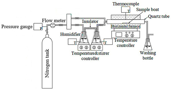
Figure 1.
Experimental setup for high-temperature oxidation under controlled water vapor atmosphere.
The oxidation process was highly controlled to ensure the accurate study of the oxidation stage. The target H2O concentrations (10%, 20%, 30% by volume) were achieved by precisely setting the volumetric flow rates of the N2 carrier gas and the H2O vapor, maintaining a constant total gas flow rate of 6 L/min throughout all experiments. The N2 flow was accurately controlled using a mass flow controller, while the H2O vapor flow was supplied by a humidifier system whose digital meter provided continuous monitoring and control to maintain the set flow rate. Numerical calculations were used to determine the exact flow settings; for instance, the 10% H2O condition required setting the H2O flow to 0.6 L/min and the corresponding N2 flow to 5.4 L/min. Similar precise calculations were applied to the 20% (1.2 L/min H2O; 4.8 L/min N2) and 30% (1.8 L/min H2O; 4.2 L/min N2) conditions. Following the 1 min oxidation period, the specimen was allowed to cool inside the furnace to room temperature under the controlled N2 atmosphere.
The Clausius–Clapeyron equation describes the relationship between temperature and vapor pressure and was employed to estimate the temperature corresponding to water vapor contents of 10%, 20%, and 30%, as follows.
where P is the vapor pressure (0.10, 0.20, and 0.30 atm), is the latent heat of vaporization of water (40,893 J/mol), is the gas constant (8.314 J/mol K), is the temperature (K), and 373 is the reference temperature (boiling point of water at 1 atm). Using this equation, the temperature corresponding to 10%, 20%, and 30% of the vapor pressure of water were determined to be 317.50 K (44.55 °C), 332.43 K (59.43 °C), and 341.79 K (68.79 °C), respectively.
2.2. Characterization of Microstructure
The morphology and composition of the oxide scale were characterized using scanning electron microscopy (SEM), energy dispersive spectroscopy (EDS), and X-ray diffraction (XRD). SEM analysis (Quanta 450, Quanta Computer Inc., Taoyuan City, Taiwan) provided high-resolution imaging of the surface morphology. EDS performed with SEM was used to identify the relative concentrations of key elements within the oxide layer. To further analyze the phase composition of the oxide scale, XRD measurements were carried out using a Bruker D8 Advance diffractometer, Bruker, Billerica, MA, USA with Cu Kα radiation (λ = 0.15406 nm). The diffraction data were collected with a step size of 0.02° and a counting time of 0.5 s per step.
2.3. Adhesion Behavior of the Oxide Scale
The adhesion of the oxide scale was evaluated using a tensile test to determine the interfacial strength between the oxide layer and the steel substrate. The tensile test was performed at room temperature under constant displacement control at a fixed strain rate of 0.04/s until the specimen fractured. This study introduces an initiating methodology for oxide scale adhesion characterization. During deformation, oxide scale failure was thoroughly observed and captured in real-time using a specially designed system featuring a high-magnification lens coupled with a high-resolution charge-coupled device (CCD) camera, specifically the imaging source DFK 23G274 (The Imaging Source, LLC, Charlotte, NC, USA) (a GigE camera utilizing a color CMOS sensor with a resolution of 2592 × 2048 pixels or 5.3 MP).
Video data were precisely recorded at 640 × 480 pixels resolution and a frame rate of 7.5 frames per second, with our internally developed image framework program specifically engineered to control and integrate the complex data acquisition. This coupling of real-time visual delamination tracking with quantitative mechanical adhesion data provides a comprehensive and enhanced understanding of the scale–steel interface behavior in hot-rolled recycled steel. The experimental setup and specimen dimensions are depicted in Figure 2, showcasing the novel design custom-engineered for this specific investigation.
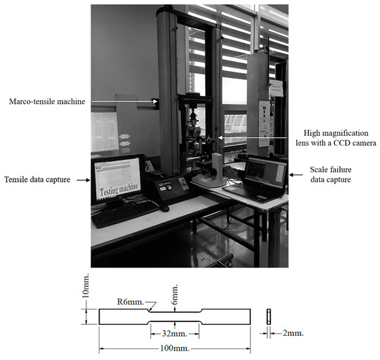
Figure 2.
Tensile testing machine with integrated real-time observation system (top) and dimensions of the tensile specimen (bottom).
3. Results and Discussion
3.1. Morphological and Chemical Characteristics of Oxide Scale
To gain a comprehensive understanding of oxide scale formation, scanning electron microscopy (SEM) and energy dispersive spectroscopy (EDS) were employed to analyze the scale–steel interface of medium and thin slabs subjected to oxidation in a gas mixture of 30% H2O and 70% N2. The SEM cross-sectional images of the medium slab (Figure 3) and thin slab (Figure 4) reveal a clear morphological distinction. While the medium slab overall develops a relatively thinner and more compact scale structure compared to the thin slab, the most significant difference lies precisely at the scale–steel interface. EDS analysis consistently confirms a multi-layered structure with the outer scale dominated by Fe3O4 and Fe2O3. However, high-resolution SEM and EDS mapping reveal a pronounced enrichment and segregation of residual silicon (Si) at the metal/oxide boundary, indicating preferential internal oxidation that forms an inner interfacial oxide layer, identified as Fe2SiO4 (Fayalite) in both slab types.
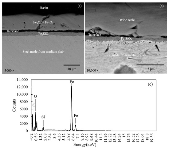
Figure 3.
Cross-sectional SEM image (a), magnified at interface (b), and corresponding EDS pattern at interface (c) of steel made from medium slab.
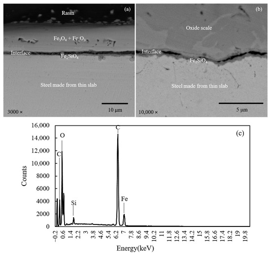
Figure 4.
Cross-sectional SEM image (a), magnified at interface (b), and corresponding EDS pattern at interface (c) of steel made from thin slab.
Specifically, Figure 3 (medium slab, higher Si content) demonstrates the formation of a Fe2SiO4 layer that is significantly thicker, highly dense, and laterally continuous. This continuity is crucial as the layer functions as an effective passive barrier, significantly suppressing the outward diffusion of Fe ions from the substrate and retarding the inward diffusion of oxygen. Conversely, Figure 4 (thin slab) exhibits a Fe2SiO4 layer that is noticeably thinner, porous, and discontinuous, failing to provide complete coverage of the metallic substrate. This difference in interfacial morphology (Fe2SiO4 continuity) is the structural feature directly dictating the mechanical adhesion behavior measured in later tests. The thick, continuous barrier shown in Figure 3 promotes a stronger interfacial bond and forces crack propagation along a more energy-intensive, tortuous path, directly correlating with the observed higher adhesion strength for the medium slab.
Table 2 presents a comparative analysis of the elemental composition of the medium and thin slabs, as determined by energy dispersive spectroscopy (EDS) at the scale–steel interfaces. The EDS data for Table 2 were acquired by performing a point measurement positioned directly on the interfacial Si-rich oxide layer adjacent to the steel substrate. The data was shown in both weight percent (wt.%) and atomic percent (at.%). The comparison reveals variations in the concentration of key elements such as iron, silicon, oxygen, and carbon between the two slab types. The analysis of silicon content at the scale–steel interface revealed a significantly higher silicon content in the medium slab compared to the thin slab. The increased silicon content at the interface plays a crucial role in the oxidation rate. Silicon, present in the form of SiO2 and Fe2SiO4, promotes the formation of a more protective oxide layer [3]. The protective effect of this oxide layer is evidenced by the reduced scale thickness shown in Figure 5 and supported by the data in Table 3. Moreover, increasing the water vapor content leads to a higher partial pressure of oxygen due to the equilibrium between H2O, H2, and O2. As the oxygen partial pressure increases, the Gibbs free energy for oxide formation decreases, thereby making oxide formation more thermodynamically favorable. This factor contributes to the formation of a thicker oxide scale. Furthermore, the thickness data used to construct Figure 5 and the mean values in Table 3 were obtained by measuring the scale layer at five distinct points across the cross-section of each specimen, and the reported standard deviation (SD) in Table 3 reflects the statistical variation among these five measurement points.

Table 2.
Comparative analysis of elemental composition at scale–steel interfaces on steel made from medium and thin slabs.
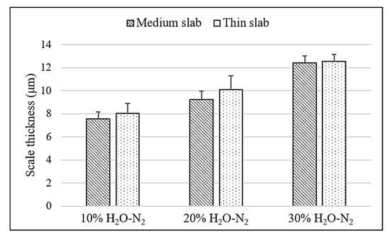
Figure 5.
Variation in oxide scale thickness across different slab types.

Table 3.
Comparison of oxide scale thickness across medium and thin slabs.
Figure 6 presents the X-ray diffraction (XRD) patterns on the oxide scale of the medium and thin slabs oxidized in 30%H2O-N2 at 900 °C, revealing the presence of hematite (Fe2O3, ICDD 01-087-1166) at 2θ of 24.2°, 33.2°, 40.9°, 49.5°, 54.1°, and 64.7°, respectively. Magnetite (Fe3O4, JCPDS-ICDD 07-0322) was observed at 2θ of 30.3°, 35.3°, 43.6°, 57.5°, and 63.2°, respectively, while iron (Fe, ICDD 00-001-1262) was observed at 2θ of 44.68°. The XRD analysis indicates that hematite and magnetite were predominantly located in the outermost layer of the oxide scale. The presence of both hematite and magnetite suggests that the oxide scale develops a multi-layered structure. It was noted that wustite (FeO) was not observed in the oxide scale.
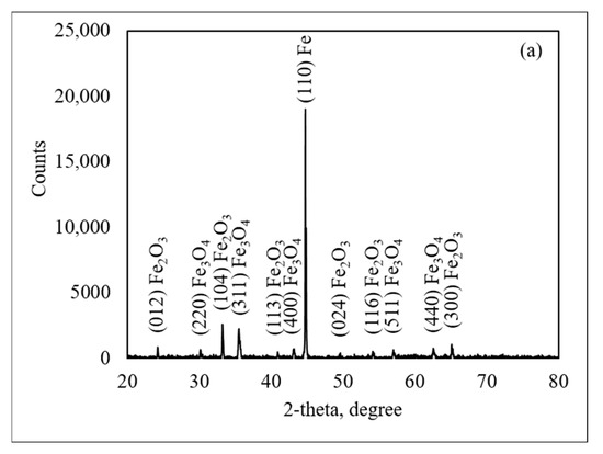
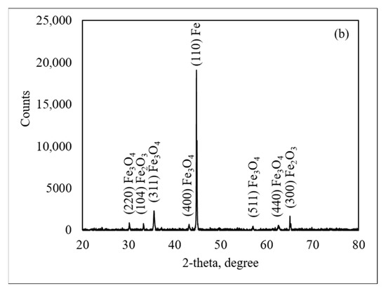
Figure 6.
X-ray diffraction patterns of steel made from medium slab (a) and thin slab (b).
The presence of an iron (Fe) peak in XRD patterns can be explained by the Fe-O phase diagram. Since the steel was allowed to cool slowly in the furnace, it followed an equilibrium cooling stage. Wustite becomes thermodynamically unstable at temperatures below 570 °C and tends to decompose into magnetite (Fe3O4) and metallic iron (Fe). On the contrary, at temperatures above 570 °C, wustite is more stable and tends to increase as the oxidation reaction progresses. Under these conditions, wustite can form more readily as Fe2+ ions diffuse rapidly through the oxide scale at high temperatures. The phase transition of wustite into magnetite and iron follows the eutectoid reaction, which can be represented by the following Reactions (2) and (3). In Reaction (2), the stability of wustite increases with temperature, which becomes increasingly thermodynamically favored as the reaction proceeds. In Reaction (3), wustite decomposes into magnetite and iron at lower temperatures.
3.2. Thermodynamics of Oxide Scale Formation
High-temperature oxidation leads to the formation of oxide scale on steel. For foundational understanding, the process is considered thermodynamically: the water vapor in the furnace atmosphere dissociates to produce oxygen, acting as the main oxidizing agent. The maximum oxygen partial pressure available for oxidation is governed by the thermodynamic equilibrium of Reaction (4).
Based on [29] and Equation (5), let y represent the initial percentage of water vapor in the gas mixture, taken as 10%, 20%, and 30% H2O in this study. If x denotes the portion of water vapor that dissociates, the remaining water vapor is ()%. As a result of the dissociation, the generated amounts of hydrogen and oxygen are % and ()%, respectively. The corresponding standard Gibbs free energy of formation is given by the following.
According to thermodynamic principles, at 900 °C, as determined by the equilibrium of Reaction (4), the following values were obtained for different water vapor concentrations. For 10% H2O, the equilibrium percentage of hydrogen () was 2.36 × 10⁻⁵, resulting in a water vapor-to-hydrogen partial pressure ratio of 423,729 (10 / 2.36 × 10⁻⁵), and a corresponding oxygen partial pressure of 1.18 × 10⁻⁵. For 20% H2O, x was 3.75 × 10⁻⁵, giving a partial pressure ratio of 533,333 and an oxygen partial pressure of 1.88 × 10⁻⁵. At 30% H2O, increased to 4.91 × 10⁻⁵, with a pressure ratio of 610,998 and an oxygen partial pressure of 2.46 × 10⁻⁵. During the oxidation of iron, hydrogen is concurrently generated as a byproduct, increasing the hydrogen concentration in the furnace. However, this change does not affect the overall stability of oxide formation due to the high initial ratio (exceeding 400,000), which is significantly greater than the equilibrium ratio required for oxide formation.
3.3. Oxidation Mechanism
To evaluate the influence of silicon content on defect formation in the oxide scale, the point defect concentration was calculated using a modified Arrhenius-type relation at 900 °C. The difference in Gibbs free energy of defect formation, ), as a function of silicon and water vapor contents, was assumed between the medium slab (0.254% Si) and the thin slab (0.153% Si). This effect was approximated as a linear increase in ) with increasing Si content, reflecting the role of silicon in stabilizing the oxide lattice. During oxidation, silicon can form stable phases such as SiO2 or Fe2SiO4, which tend to localize near the scale–steel interface. These phases contribute to reducing the mobility of point defects such as vacancies and electron holes. The modified Arrhenius-type Equation (6), together with Equation (7), was applied to adjust the Gibbs free energy of defect formation as a function of both silicon and water vapor contents ).
where is the total concentration of point defects (arbitrary unit), is the Gibbs free energy of defect formation as a function of silicon and water vapor contents (J/mol), is the gas constant (8.314 J/mol K), and is the temperature (K).
where is the Gibbs free energy of defect formation at Si and water vapor , is the reference value of 1.80 × 10⁵ J/mol (at = 0.153%, = 10%), is the decrease in /1% H2O (e.g., −100 J/mol), is the H2O concentration (%), is the reference H2O (e.g., 10%), is the increase in /0.1 wt.% Si (e.g., +1000 J/mol), is the actual Si content (wt.%), and is the reference Si content (e.g., 0.153 wt.%). The calculated defect concentrations are summarized in Table 4. The results show that for the medium slab (0.254% Si), increasing H2O content from 10% to 30% led to an increase in relative (X) from 0.90 to 1.10, representing an approximate 22% increase in defect concentration. For the thin slab (0.153% Si), the corresponding relative (X) increased from 1.00 to 1.22, indicating an approximate 22% increase as well, suggesting that the effect of water vapor on defect formation is independent of silicon content within this range. This implies that H2O influences the Gibbs free energy of defect formation uniformly, regardless of small variations in Si, and that the primary driver of the defect concentration increase is the water vapor content itself, not the Si level. The role of Si was seen more clearly in the absolute difference in (X), not in the rate of increase due to water vapor. When comparing the two slabs at the same H2O contents, the thin slab constantly exhibited higher defect concentrations, about 10% higher at 20% H2O and approximately 11% higher at 30% H2O. This confirms that increasing water vapor promotes defect formation, while higher silicon content suppresses it by increasing , thereby reducing the concentration of point defects in the oxide scale. It was noted that relative defect concentration was determined using the normalized form, defined as relative , here the subscript is the H2O concentration (%), and the reference value is taken from the thin slab at 10% H2O.

Table 4.
Calculated Gibbs free energy of defect formation () and resulting defect concentrations (X) for thin and medium slabs at varying H2O contents.
3.4. Adhesion Behavior of the Oxide Scale
The adhesion of oxide scale to hot-rolled steel substrates is a critical characteristic of the steel production process, significantly impacting descaling efficiency. This complex phenomenon is influenced by the steel chemical composition and the oxidizing atmosphere. This section introduces and utilizes an innovative and unique approach to comprehensively investigate the mechanical adhesion behavior of oxide scale on steel substrates.
The method employs an innovative combination of a macro-tensile testing machine and a precisely corresponding, real-time CCD camera system. The tensile machine accurately measures adhesion strength by applying a controlled tensile force, while the CCD camera provides continuous, real-time visual monitoring of scale detachment during the test. This unique integration allows for measuring the strain required to separate the oxide scale from the steel surface, thereby providing both accurate quantitative data (e.g., adhesion energy) and detailed qualitative assessments (e.g., spallation ratio).
The adhesion characteristics are examined through the following three critical analyses: detailed visual observation of the oxide scale spallation process during tensile loading, determination of the critical strain initiating the first spallation event, and subsequent calculation of the mechanical adhesion energy using the Galerie–Dupeux model, rigorously based on U.R. Evans’ criterion.
Figure 7 illustrates the evolution of scale failure on steel produced from both medium and thin slabs. The image, being captured by the high-resolution CCD camera, intentionally shows the entire surface of the specimen covered by the oxide scale. The horizontal band seen in the image serves as a marker indicating the specimen centerline, while scale spallation is observed as small, dark spots against the background oxide. During tensile loading, the initial spallation of the oxide scale was observed, marking a critical point for evaluating the interfacial bonding strength between the scale and the steel substrate. The results presented herein provide highly reliable data on the interfacial bonding strength unique to this recycled steel system.
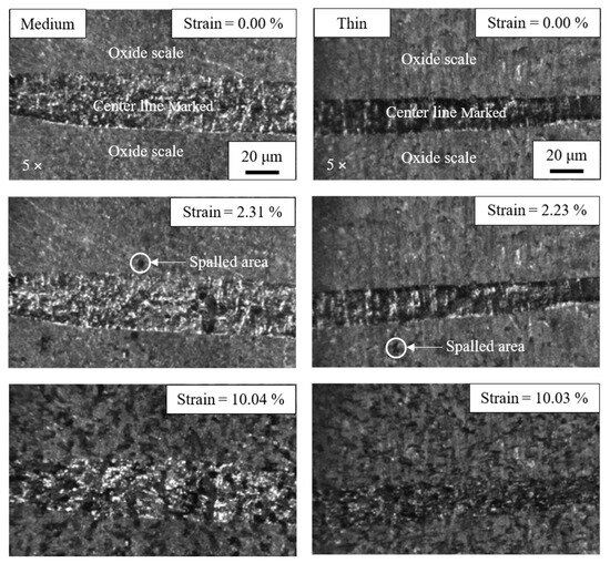
Figure 7.
Evolution of scale failure on steel made from medium slab (left) and thin slab (right) oxidized in 30% H2O-N2 during tensile load.
Figure 8 illustrates a comparison of the strain initiating the first spallation and the spallation ratio of steel for different slab types at the same water vapor content. The strain initiating the first spallation is defined as the area where the oxide scale first spalls from the steel surface under tensile loading. The spallation ratio was calculated by dividing the area of spalled oxide scale by the total area captured in the image. These values were obtained through video processing and compared with data from the tensile tests. Across all three water vapor concentrations, the scale adhesion behavior of different slab types varies significantly. Steel made from medium slab with higher silicon content tends to exhibit higher scale adhesion. The higher scale adhesion observed in steel containing higher silicon content was due to the formation of protective and adherent oxide layers, particularly silicon dioxide (SiO2). This oxide forms a dense and thermodynamically stable barrier that effectively inhibits oxygen diffusion into the substrate, promoting internal oxidation of fayalite (Fe2SiO4) by Fe diffusion from substrate, as evidenced in Figure 3 and Figure 4.
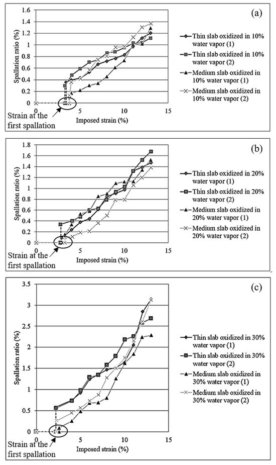
Figure 8.
Strain initiating the first spallation and spallation ratio for steel oxidized in 10% (a), 20% (b), and 30% (c) of H2O-N2 with different slab types.
SiO2 and Fe2SiO4 provide reduced thermal stress at the scale–substrate interface. The thermal stress was significantly reduced when the thermal expansion coefficients of oxide and steel were closely matched. In this situation, the presence of SiO2 and Fe2SiO4, which exhibit lower mismatch with the steel substrate, leads to better mechanical compatibility during thermal oxidation, therefore minimizing interfacial cracking and improving scale adhesion. The thermal expansion coefficients (CTEs) have been reported for silicon dioxide (SiO2) as approximately 0.24 × 10⁻⁶/°C [30] and for fayalite (Fe2SiO4) as 9.5 × 10⁻⁶/°C [31]. When considering these values, the CTE of fayalite is notably closer to that of steel which is approximately 11.8 × 10⁻⁶/°C [32]. It can be noted that iron oxides, such as wustite (FeO) is 12.0 × 10⁻⁶/°C, magnetite (Fe3O4) is 9.0 × 10⁻⁶/°C, and hematite (Fe2O3) is 8.50 × 10⁻⁶/°C [31]. As observed in Figure 3 and Figure 4, the scale–steel interface of steel made from medium slab exhibits a thicker layer of Fe2SiO4 compared to that made from thin slab. This increased thickness of Fe2SiO4 contributes to reduced thermal stress due to the closer match in thermal expansion coefficients between the oxide layer and the steel substrate, which in turn enhances scale adhesion in steel made from medium slab.
Figure 9 illustrates the comparation of strain initiating the first spallation and the spallation ratio of steel under different water vapor contents, compared for the same slab type. This result provides comprehension into the adhesion behavior of oxide scale under the influence of water vapor content. The results show that an increase in water vapor content tends to weaken the adhesion of the oxide scale, possibly due to enhanced oxidation kinetics and the promotion of defects at the scale–substrate interface.
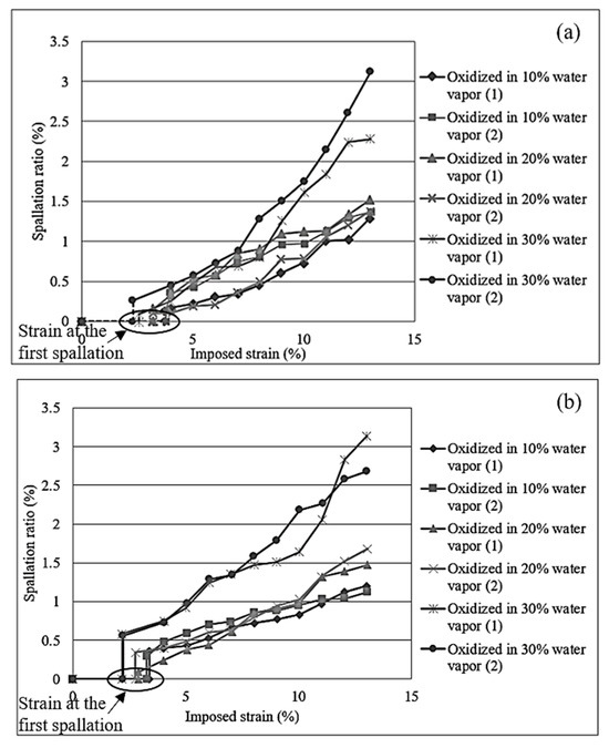
Figure 9.
Strain initiating the first spallation and spallation ratio for steel made from medium slab (a) and thin slab (b) oxidized in 10%, 20%, and 30% of H2O-N2.
For the strain initiating the first spallation and the spallation ratio of scale, at 10% H2O-N2, the oxide scale remains more adherent, with a higher strain required to initiate the first scale spallation, and the spallation ratio remains relatively low. The limited availability of water vapor results in reduced dissociation into free oxygen and hydrogen, corresponding to reduced weakening of the oxide–steel interface. Under this condition, a more compact and protective oxide scale can form, capable of withstanding higher mechanical stress before spallation takes place. This was attributed to the lower hydrogen diffusion resulting from the limited decomposition of water vapor and slight hydrogen release during oxide growth, which reduced hydrogen embrittlement and helped maintain better adhesion between the oxide scale and the steel substrate.
At 20% H2O-N2, the strain required to initiate the first scale spallation decreases, while the spallation ratio increases. This indicates that the oxide scale becomes less adherent under moderate water vapor conditions. This might be due to the increased availability of oxygen, which accelerates the oxidation process and leads to the formation of thicker oxide layers. Simultaneously, the enhanced dissociation of H2O and hydrogen released during oxide formation introduces more hydrogen into the system. Hydrogen tends to diffuse toward the oxide–steel interface, weakening the bonding strength between the oxide scale and the substrate. As a result, spallation initiates at a lower strain compared to the condition with 10% H2O-N2.
At 30% H2O-N2, the strain required to initiate scale spallation is the lowest, while the spallation ratio is significantly higher. This indicates a reduction in scale adhesion due to the aggressive oxidation environment. The higher concentration of water vapor leads to extensive dissociation, providing more free oxygen to accelerate the growth of iron oxides. These oxides were less adherent and exhibited a higher tendency to crack under tensile stress. This is due to hydrogen generated from water vapor dissociation and as a byproduct of oxide formation, which is believed to diffuse and accumulate at the scale–steel interface, weakening interfacial adhesion and promoting early spallation of the oxide layer under mechanical loading.
Based on the results for the strain initiating the first spallation and the spallation ratio of steel made from medium and thin slabs under 10%, 20%, and 30% H2O-N2 conditions, it is evident that increasing water vapor content promotes earlier spallation and greater scale detachment, while the presence of silicon in the steel enhances scale adhesion by the formation of more protective and adherent oxide phase. This information provides understanding into how alloy composition and water vapor concentration influence oxide scale adhesion. Understanding these factors is essential for assessing scale removal behavior during hot-rolled steel processing, as poor adhesion can lead to easier scale detachment, whereas strong scale adhesion may necessitate the use of more aggressive descaling methods or higher energy input to ensure effective removal. Such data can support the optimization of process parameters to balance oxide protection and descaling efficiency in industrial production, ultimately leading to improved surface quality of steel products.
The mechanical adhesion energy between the oxide scale and the steel substrate was quantitatively calculated using the Galerie–Dupeux model, rigorously based on U.R. Evans’ criterion [33,34] for scale spallation. Critically, our work introduces a novel application of this model by uniquely leveraging the precise experimental tensile data obtained from our integrated real-time observation system. This provides a highly reliable and distinct assessment of the interfacial bonding strength specifically for this interesting, recycled steel system, extending beyond conventional applications, with the calculations performed using Equation (8).
where is the mechanical adhesion energy (J/m2), is the stored energy in the oxide scale until the first spallation (J/m3), and is the oxide scale thickness (m).
The mechanical adhesion energy equation incorporates the stored energy () and the oxide scale thickness (). For calculation of the stored energy, the evolution of stress–strain relationships during the testing process was typically observed along both the tensile axis (designated as ) and the transverse tensile axis (designated as ), whereas it was conventionally assumed that the stress along the axis perpendicular to the interface (referred to as ) was negligible, as illustrated in Figure 10. Initially, the mechanical behavior of the steel substrate, denoted with the subscript , was characterized by elastic deformation, followed by a transition into the plastic deformation regime, while the oxide scale, denoted with the subscript , maintains an elastic state until the onset of the first spallation. To further clarify the analysis, a secondary subscript was employed to indicate the primary axis of interest (either and ), and superscripts were utilized to denote specific conditions, for residual stress, for the elastic behavior of the steel, and for its plastic behavior. This framework allows for a comprehensive understanding of the mechanical adhesion between the steel substrate and the oxide scale throughout the tensile testing process.
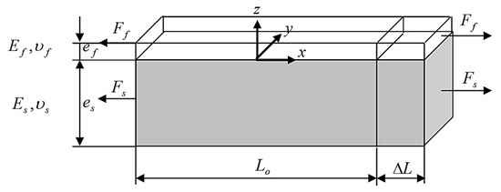
Figure 10.
Schematic representation of the steel substrate and the oxide scale during tension.
To accurately quantify the stored energy within this work, it was essential to consider several key mechanical parameters. It should be noted that the values employed in this study were derived from the average properties of hematite and magnetite oxides, as determined from the X-ray diffraction analysis. These include the Young’s modulus of the oxide scale (), measured as 210 GPa [35,36,37,38,39,40,41], and the Young’s modulus of the steel substrate (), recorded as 210 GPa [42]. Furthermore, it was important to note that both the Poisson’s ratios for the steel and the oxide were assumed to be equal at 0.3 ( = = 0.3) [37,39,43,44,45], under the assumption of a perfectly adherent steel–oxide interface. Additionally, the compressive residual stress present in the oxide layer () was quantified as −0.2 GPa [46,47,48,49,50,51]. Lastly, the strain at the limit of elasticity for the iron oxide ( was determined to be 0.0015, corresponding to 0.15% [20], which was critical for understanding the deformation behavior of the oxide under stress. The stored energy within the oxide scale, with respect to both the and directions, can be determined using a straightforward relationship that accounts for the mechanical parameters associated with the deformation of the oxide. This relation effectively captures the contributions of stress and strain in each respective direction, allowing for a comprehensive assessment of the stored energy due to the oxide mechanical response under applied loads.
Upon cooling from the oxidation temperature to room temperature, the distinct thermal expansion coefficients exhibited by the substrate and the oxides lead to the generation of thermal stresses, which arise as a consequence of differential contraction rates. These thermally induced stresses combine with the pre-existing stress state established at elevated temperatures, ultimately contributing to the residual stresses that can be experimentally measured at room temperature. During the process of tensile loading, the substrate experiences elastic tension up to its limit of elasticity (), after which it undergoes plastic deformation. In contrast, the oxide scale remains in an elastic state until the occurrence of the first spallation incident. This critical strain, referred to as (), was determined using Equation (9). Consequently, the strain experienced by the oxide along the -axis during the subsequent plastic deformation phase, as illustrated in stage 3 of the stored energy () analysis, can be expressed mathematically as . This formulation emphasizes the relationship between the strain in the oxide and the overall mechanical behavior of both the substrate and the oxide layer throughout the loading process.
The development of stored energy within the oxide scale can be analyzed through three successive stages, each characterized by specific mechanical behaviors and contributions to the overall energy accumulation process. These stages encompass the initial elastic deformation, the transition to plastic deformation, and the subsequent spallation occurrence, which collectively influence the oxide’s energy characteristics under tensile loading conditions. Each stage plays a critical role in defining the energy profile of the oxide as it responds to external stressors.
In stage 1 (A to B), the growth of the oxide scale occurs concurrently with its cooling, a process that significantly contributes to the accumulation of residual stress within the oxide structure. As the oxide forms and subsequently cools from the high temperatures associated with oxidation, the differential thermal expansion between the oxide and the substrate leads to the development of internal stresses. This accumulation of residual stress is critical, as it establishes the foundational mechanical state of the oxide layer, influencing its behavior in subsequent stages of deformation and adhesion.
In stage 2 (B to C), both the substrate and the oxide scale experience elastic tension, which was characterized by their ability to deform reversibly under applied stress. During this point, the substrate e undergoes elastic deformation up to its limit of elasticity, while the oxide maintains an elastic state until the point of first spallation. This simultaneous elastic behavior was crucial, as it allows both materials to absorb energy without permanent deformation, contributing to the overall mechanical integrity of the system. The interactions between the tensile stresses in the substrate and the oxide play a significant role in the subsequent stages of deformation and influence the stored energy dynamics within the oxide layer.
In stage 3 (C to D), the system enters a critical phase where both the substrate and the oxide film continue to experience tensile stress. At this stage, the substrate undergoes plastic deformation, meaning it has exceeded its elastic limit and is now deforming irreversibly under the applied load. Meanwhile, the oxide scale remains in an elastic state. However, this elastic behavior of the oxide persists only until the first spallation occurs, marking a significant mechanical failure where the adhesion between the oxide and the substrate begins to degrade. This phase is pivotal in the energy storage process, as the strain energy within the oxide reaches a critical point, contributing to the initiation of spallation and impacting the overall adhesion and mechanical stability of the oxide scale.
The stored energy in the oxide scale, in both the and directions, was represented by the equation , which corresponds to the area under the stress–strain curve as shown in Figure 11. The area under the stress–strain curve precisely quantifies the stored energy within the oxide scale, considering both the tensile () and transverse () directions. This is a common and critical analysis for oxide layers, as internal stresses and stored energy can significantly impact adhesion energy.
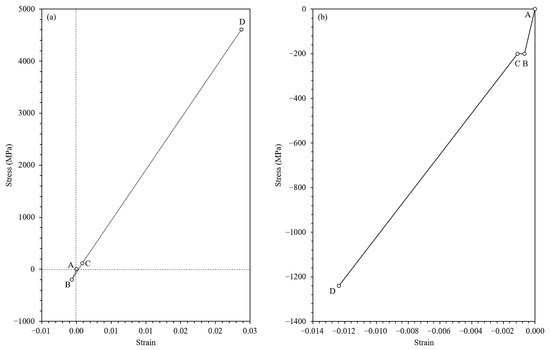
Figure 11.
The evolution of stress and strain during tensile loading along the x-axis (tensile direction) (a) and the y-axis (transverse direction) (b).
Table 5 summarizes the comprehensive set of critical experimental results obtained from this study, detailing the scale thickness, the strain at the initiation of the first spallation, and the calculated mechanical adhesion energy for hot-rolled steel produced from both medium and thin slabs. A consistent increase in oxide scale thickness was observed within both slab types when the water vapor concentration increased from 10% to 30% H2O-N2. For medium slab steel, the scale thickness increased from 7.532 μm at 10% H2O to 12.420 μm at 30% H2O, while thin slab steel showed a similar trend, increasing from 8.035 μm to 12.550 μm. This growth in scale thickness was attributed to enhanced oxidation kinetics under higher water vapor content. Strain initiating the first spallation, used as a qualitative indicator of scale adhesion, showed an inverse trend with increasing water vapor. In medium slab samples, the strain decreased from 3.783% at 10% H2O to 2.441% at 30% H2O. Thin slab samples exhibited lower strain values overall, ranging from 3.346% to 2.214% as water vapor content increased. This suggests that higher water vapor not only accelerates oxide growth but also promotes defect formation (e.g., and ), reducing the mechanical adhesion of the scale–substrate interface. The calculated mechanical adhesion energy, as illustrated in Figure 12 and serving as a quantitative indicator of interfacial bonding strength, further confirmed the weakening effect induced by increasing water vapor content. The decrease in adhesion energy with higher H2O levels indicates weaker bonding between the oxide scale and the steel surface. This result agrees with the observed increase in scale thickness and the formation of more defects at the interface. For medium slabs, adhesion energy decreased from 413.8 J/m2 to 273.6 J/m2 as water vapor increased. Thin slabs followed the same trend, with values decreasing from 342.1 J/m2 to 224.1 J/m2. The higher adhesion energy in medium slab steel under all conditions suggests a more compact and adherent scale structure. Additionally, the higher silicon content found in medium slab steel contributed to enhanced scale adhesion. Silicon was known to promote the formation of a thin, continuous SiO2-rich layer at the scale–substrate interface, which acts as a diffusion barrier, suppressing rapid Fe ion migration and limiting scale growth. This barrier effect not only enhances the overall scale morphology but also helps maintain a more adherent interface. As a result, even with increased water vapor, the medium slab steel maintained stronger bonding at the scale–steel interface and showed higher resistance to spallation compared to the thin slab steel.

Table 5.
Summary of key experimental results on oxide scale thickness and adhesion behavior of hot-rolled steel produced from medium and thin slabs under various H2O-N2 oxidations at 900 °C.
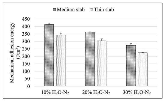
Figure 12.
Comparison of mechanical adhesion energy of oxide scale on hot-rolled steel produced from medium and thin slabs oxidized under various H2O-N2 atmospheres at 900 °C.
To better illustrate the interrelated effects of water vapor on oxide scale growth and adhesion behavior, Figure 13 presents a combined comparison of oxide scale thickness, strain at the first spallation, and mechanical adhesion energy under different water vapor conditions for both medium and thin slab steels. This clearly illustrates the opposite trends between oxide scale thickness and adhesion indicators, as the scale becomes thicker with increasing water vapor, both the strain required to initiate spallation and the mechanical adhesion energy decrease. These results indicate that increased oxidation, taken by higher water vapor content, reduces the bonding strength at the scale–substrate interface. Moreover, the comparison between the two slab types shows that medium slab steel consistently maintains better adhesion than thin slab steel under the same condition. Therefore, this supports the conclusion that controlling both oxidation environment and the retained Si content in the slab is important for improving surface quality in hot-rolled steel.
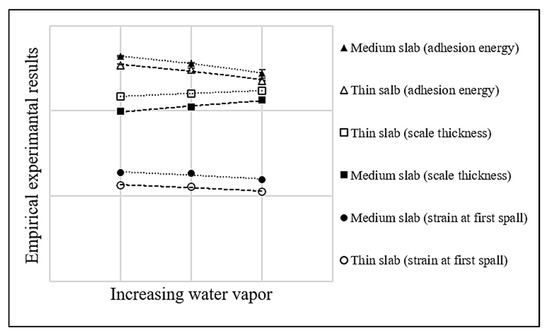
Figure 13.
Relationship between water vapor content and scale thickness, strain at first spall, and adhesion energy of hot-rolled steel produced from medium and thin slabs.
Based on microscopic observations and scale adhesion results, the proposed mechanism of scale adhesion behavior under the influence of water vapor is illustrated in Figure 14. At 10% H2O, the scale remains relatively dense with minimal defect and strong adhesion to the substrate. As the water vapor concentration increases to 20%, defects such as vacancies and brittleness caused by hydrogen embrittlement become more evident within the oxide scale, weakening the bonding strength. At 30% H2O, the oxide scale exhibits a significant increase in vacancy formation and hydrogen embrittlement, particularly near the scale–steel interface, resulting in decreased adhesion strength and more extensive spallation behavior.
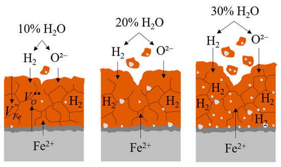
Figure 14.
Illustration of the oxidation and adhesion mechanisms under water vapor conditions.
4. Conclusions
This study successfully quantified the mechanical adhesion energy of oxide scale on hot-rolled recycled steel, employing a novel macro-tensile method. The findings provide critical parameters for industrial optimization. The main conclusions are itemized as follows:
- 1.
- Quantitative metric and innovation: The macro-tensile method successfully provided a reliable quantitative metric, the scale adhesion energy (J/m2), enabling precise mechanical assessment of scale bonding.
- 2.
- Effect of water vapor: The data established a precise inverse correlation between steam content and scale adhesion strength. Increasing water vapor concentration was shown to substantially degrade scale adhesion across different steel types due to the formation of defective scale layers.
- 3.
- Critical role of silicon: Residual Si content is a critical factor dictating the formation of protective interfacial layers. High-Si steel exhibited significantly higher scale adhesion energy than low-Si steel under all tested steam conditions.
- 4.
- Industrial recommendation: The findings are directly translatable into specific recommendations for production. Steel mills should strictly minimize residual silicon content and maintain the furnace steam concentration at an intermediate level (approximately 20%). This strategy optimizes scale formation conditions, ensuring a superior strip surface quality and facilitating efficient scale removal.
Funding
This research budget was allocated by the National Science, Research, and Innovation Fund (NSRF) and King Mongkut’s University of Technology North Bangkok (KMUTNB-FF-68-A-08).
Data Availability Statement
The original contributions presented in this study are included in the article. Further inquiries can be directed to the corresponding author.
Acknowledgments
The author would like to acknowledge the vital contribution of Thammaporn Thublaor (T.T.) for the provision of resources and funding acquisition essential for completing this study. The author also extends gratitude to G Steel Public Company Limited for supplying the materials used in this research.
Conflicts of Interest
The author declares no conflicts of interest.
References
- Fruehan, R.J. The Making, Shaping and Treating of Steel, 11th ed.; Steelmaking and Refining Volume; The AISE Steel Foundation: Pittsburgh, PA, USA, 1998. [Google Scholar]
- Ginzburg, V.B. Flat-Rolled Steel Process; CRC Press: Boca Raton, FL, USA, 2009. [Google Scholar]
- Ghosh, A.; Chatterjee, A. Ironmaking and Steelmaking, Theory and Practice; Prentice Hall of India: New Delhi, India, 2008. [Google Scholar]
- Kofstad, P. High Temperature Corrosion; Elsevier Applied Science: London, UK, 1988. [Google Scholar]
- Sarrazin, P.; Galerie, A.; Fouletier, J. Mechanisms of High Temperature Corrosion: A Kinetic Approach; Trans Tech Publications: Baech, Switzerland, 2008. [Google Scholar]
- Yuan, J.; Wang, W.; Zhu, S.; Wang, F. Comparison between the oxidation of iron in oxygen and in steam at 650–750 °C. Cor. Sci. 2013, 75, 309–317. [Google Scholar] [CrossRef]
- Saunders, S.R.J.; Monteiro, M.; Rizzo, F. The oxidation behaviour of metals and alloys at high temperatures in atmospheres containing water vapour: A review. Pro. Mater. Sci. 2008, 53, 775–837. [Google Scholar] [CrossRef]
- Jia, Q.; Jiang, X.; Wu, C.; Chan, J.; Zhu, X.; Liu, Y.; Su, X. Effect of Si on mechanical properties and oxide film formation of AFA alloy at low oxygen pressure. Coatings 2025, 15, 602. [Google Scholar] [CrossRef]
- Stott, F.H.; Wood, G.C.; Stringer, J. The influence of alloying elements on the development and maintenance of protective scales. Oxid. Met. 1995, 44, 113–145. [Google Scholar] [CrossRef]
- Chandra-ambhorn, S.; Nilsonthi, T.; Wouters, Y.; Galerie, A. Oxidation of simulated recycled steels with 0.23 and 1.03 wt.% Si in Ar-20% H2O at 900 °C. Corros. Sci. 2014, 87, 101–110. [Google Scholar] [CrossRef]
- Yu, L.; Shen, F.; Fu, T.; Zhang, Y.; Cui, K.; Wang, J.; Zhang, X. Microstructure and oxidation behavior of metal-modified Mo-Si-B alloys: A review. Coatings 2021, 11, 1256. [Google Scholar] [CrossRef]
- Vivekanandam, V.; Joshi, S.S.; Nebreda, J.L.; Fan, Z. Effect of processing-induced oxides on the fatigue life variability of 6082 Al-Mg-Si alloy extruded components. J. Manuf. Mater. Process. 2025, 9, 247. [Google Scholar] [CrossRef]
- Zhang, Y.; Shan, Z.; Luo, L.; Li, Z.; Liang, X.; Su, Y.; Yang, T.; Zang, Y.; Jin, D. Optimizing the high-temperature oxidation resistance of Nb-Si-based alloys by adding different Ti/Mo/Hf elements. Metals 2025, 15, 439. [Google Scholar] [CrossRef]
- Yamazaki, T.; Ikeda, K.; Sekiguchi, Y.; Sato, C. Experimental investigation of adhesive joint strength and stress-based criteria under tensile/compression–shear stress state using a developed fixture. J. Adhes. 2025, 1–22. [Google Scholar] [CrossRef]
- Sun, X.; Liu, W.N.; Stephens, E.; Khaleel, M.A. Determination of interfacial adhesion strength between oxide scale and substrate for metallic SOFC interconnects. J. Power Sources 2008, 176, 167–174. [Google Scholar] [CrossRef]
- Galerie, A.; Toscan, F.; N’Dah, E.; Przybylski, K.; Wouters, Y.; Dupeux, M. Measuring adhesion of Cr2O3 and Al2O3 scales on Fe-based alloys. Mater. Sci. Forum 2004, 461–464, 631–638. [Google Scholar] [CrossRef]
- Mougin, J.; Dupeux, M.; Antoni, L.; Galerie, A. Adhesion of thermal oxide scales grown on ferritic stainless steels measured using the inverted blister test. Mater. Sci. Eng. A. 2003, 359, 44–51. [Google Scholar] [CrossRef]
- Zhao, Y.Q.; Qu, H.L.; Zhu, K.; Wu, H.; Zhou, L. Oxidation and peel-off mechanisms of oxide layer of the highly stabilized. Rare Met. Mater. Eng. 2001, 30, 35–39. [Google Scholar]
- Toscan, F.; Antoni, L.; Wouters, Y.; Dupeux, M.; Galerie, A. Oxidation kinetics and scale spallation of iron-chromium alloys with different titanium contents. Mater. Sci. Forum 2004, 461–464, 705–712. [Google Scholar] [CrossRef]
- Chandra-ambhorn, S.; Roussel-dherbey, F.; Toscan, F.; Wouters, Y.; Galerie, A.; Dupeux, M. Determination of adhesion energy of thermal oxide scales on AISI 430Ti alloy. Mater. Sci. Technol. 2007, 23, 497–501. [Google Scholar] [CrossRef]
- Hou, P.Y.; Saunders, S.R.J. A survey of test methods for scale adhesion measurement. Mater. High Temp. 2005, 22, 121–129. [Google Scholar] [CrossRef]
- Kondo, Y.; Tanei, H. Adhesive strength of oxide scale formed on low-carbon steel. J. Jpn. Soc. Technol. Plast. 2013, 54, 984–987. [Google Scholar] [CrossRef]
- Laptoiu, S.A.; Miculescu, M.; Enescu, D.; Antoniac, I.; Miculescu, F. Formation and characterization of Ti-Al intermetallic and oxide layers on Ti6Al4V as interlayers for hydroxyapatite coatings. Metals 2025, 15, 1159. [Google Scholar] [CrossRef]
- Zammit, A.; Attard, M.; Subramaniyan, P.; Levin, S.; Wagner, L.; Cooper, J.; Espitalier, L.; Cassar, G. Investigations on the adhesion and fatigue characteristics of hybrid surface-treated titanium alloy. Surf. Coat. Technol. 2022, 431, 128002. [Google Scholar] [CrossRef]
- Shinde, S.; Sampath, S. A critical analysis of the tensile adhesion test for thermally sprayed coatings. J. Therm. Spray Tech. 2022, 31, 2247–2279. [Google Scholar] [CrossRef]
- Nilsonthi, T.; Chandra-ambhorn, S.; Wouters, Y.; Galerie, A. Adhesion of thermal oxide scales on hot-rolled conventional and recycled steels. Oxid. Met. 2013, 79, 325–335. [Google Scholar] [CrossRef]
- Chandra-ambhorn, S.; Ngamkham, K.; Jiratthanakul, N. Effect of process parameters on mechanical adhesion of thermal oxide scale on hot-rolled low carbon steels. Oxid. Met. 2013, 80, 61–72. [Google Scholar] [CrossRef]
- ASTM E8M; Standard Test Methods for Tension Testing of Metallic Materials. ASTM International: West Conshohocken, PA, USA, 2024.
- Chen, R.Y.; Yuen, W.Y.D. Oxidation of low-carbon steel in 17H2O-N2 at 900 °C. Metal. Mater. Trans. A 2009, 40, 3091–3107. [Google Scholar] [CrossRef]
- Tsou, C.; Huang, Y.-S.; Li, H.-C.; Lai, T.-H. Determination of thermal expansion coefficient of thermal oxide. Sen. Mater. 2005, 17, 441–451. [Google Scholar]
- Takeda, M.; Onishi, T.; Nakakubo, S.; Fujimoto, S. Physical properties of iron-oxide scales on Si-containing steels at high temperature. Mater. Trans. 2009, 50, 2242–2246. [Google Scholar] [CrossRef]
- Cao, L.-F.; Xu, G.; Deng, P.; Wang, G.-X.; Hu, D.-J. Study on thermal expansion properties of steels. J. Univ. Sci. Technol. Beijing 2014, 36, 639–643. [Google Scholar] [CrossRef]
- Evans, H.E. Stress effects in high temperature oxidation of metals. Int. Mater. Rev. 1995, 40, 1–40. [Google Scholar] [CrossRef]
- Evans, H.E. Predicting oxide spallation from sulphur-contaminated oxide/metal interfaces. Oxid. Met. 2013, 79, 3–14. [Google Scholar] [CrossRef]
- Samsonov, G.V. The Oxide Handbook; IFI/Plenum: New York, NY, USA, 1973. [Google Scholar]
- Nagl, M.M.; Saunders, S.R.J.; Evans, W.T.; Hall, D.J. The tensile failure of nickel oxide scales at ambient and at growth temperature. Corros. Sci. 1993, 35, 965–977. [Google Scholar] [CrossRef]
- Krzyzanowski, M.; Beynon, J.H. Measurement of oxide properties for numerical evaluation of their failure under hot rolling conditions. J. Mater. Pro. Tech. 2002, 125-126, 398–404. [Google Scholar] [CrossRef]
- Ouglova, A.; Berthaud, Y.; Francois, M.; Foct, F. Mechanical properties of an iron oxide formed by corrosion in reinforced concrete structures. Corros. Sci. 2006, 48, 3988–4000. [Google Scholar] [CrossRef]
- Chicot, D.; Mendoza, J.; Zaoui, A.; Louis, G.; Lepingle, V.; Roudet, F.; Lesage, J. Mechanical properties of magnetite (Fe3O4), hematite (α-Fe2O3) and goethite (α-FeO·OH) by instrumented indentation and molecular dynamics analysis. Mater. Chem. Phys. 2011, 129, 862–870. [Google Scholar] [CrossRef]
- Hearmon, R.F.S. The elastic constants of crystals and other anisotropic materials. In Landolt-Börnstein Tables, III/11; Hellwege, K.H., Hellwege, A.M., Eds.; Springer: Berlin, Germany, 1979; Volume 854, pp. 1–244. [Google Scholar]
- Seo, M.; Chiba, M. Nano-mechano-electrochemistry of passive metal surfaces. Elec. Acta 2001, 47, 319–325. [Google Scholar] [CrossRef]
- Momber, A. Blast Cleaning Technology; Springer: Berlin/Heidelberg, Germany, 2008. [Google Scholar] [CrossRef]
- Gercek, H. Review Poisson’s ratio values for rocks. Inter. J. Rock Mech. Min. Sci. 2007, 44, 1–13. [Google Scholar] [CrossRef]
- Taniguchi, S.; Yamamoto, K.; Megumi, D.; Shibata, T. Characteristics of scale/substrate interface area of Si-containing low-carbon steels at high temperatures. Mater. Sci. Eng. A 2001, 308, 250–257. [Google Scholar] [CrossRef]
- Krzyzanowski, M.; Beynon, J.H.; Farrugia, D.C.J. Oxide Scale Behavior in High Temperature Metal Processing; Wiley-VCH: Weinheim, Germany, 2010. [Google Scholar]
- Panicaud, B.; Renault, P.O.; Grosseau-Poussard, J.L.; Dinhut, J.F.; Thiaudière, D.; Gailhanou, M. Measurement of stress in phosphated-iron oxide layers by In-situ diffraction of synchrotron radiation. Mater. Sci. Forum 2002, 404–407, 809–816. [Google Scholar] [CrossRef]
- Kim, B.-K. High Temperature Oxidation of Low Carbon Steel. Ph.D. Thesis, McGill University, Montréal, QC, Canada, 2003. [Google Scholar]
- Panicaud, B.; Grosseau-Poussard, J.L.; Girault, P.; Dinhut, J.F.; Thiaudière, D. Comparison of growth stress measurements with modelling in thin iron oxide films. Appl. Sur. Sci. 2006, 252, 8414–8420. [Google Scholar] [CrossRef]
- Juricic, C.; Pinto, H.; Cardinali, D.; Klaus, M.; Genzel, C.; Pyzalla, A.R. Evolution of microstructure and internal stresses in multi-phase oxide scales grown on (110) surfaces of iron single crystals at 650 °C. Oxi. Met. 2010, 73, 115–138. [Google Scholar] [CrossRef]
- Panicaud, B.; Grosseau-Poussard, J.L.; Renault, P.O.; Dinhut, J.F.; Thiaudière, D.; Gailhanou, M. In-situ stress determination in thermally-grown iron oxide scales using X-ray diffraction of synchrotron radiation. J. Neut. Res. 2004, 12, 57–61. [Google Scholar] [CrossRef]
- Juricic, C.; Pinto, H.; Wroblewski, T.; Pyzalla, A. Dependence of oxidation behavior and residual stresses in oxide layers on armco iron substrate surface condition. Mater. Sci. Forum. 2006, 524–525, 963–968. [Google Scholar] [CrossRef]
Disclaimer/Publisher’s Note: The statements, opinions and data contained in all publications are solely those of the individual author(s) and contributor(s) and not of MDPI and/or the editor(s). MDPI and/or the editor(s) disclaim responsibility for any injury to people or property resulting from any ideas, methods, instructions or products referred to in the content. |
© 2025 by the author. Licensee MDPI, Basel, Switzerland. This article is an open access article distributed under the terms and conditions of the Creative Commons Attribution (CC BY) license (https://creativecommons.org/licenses/by/4.0/).