Article

Impact Butt Joining of Copper C1100 and Aluminum Alloy A6061-T6 Plates and Rolling of Joined Plate

1
Department of Mechanical Engineering, Gifu University, 1-1 Yanagido, Gifu City 501-1193, Japan
2
Graduate School of Engineering, Gifu University, 1-1 Yanagido, Gifu City 501-1193, Japan
*
Author to whom correspondence should be addressed.
Metals 2025, 15(11), 1207; https://doi.org/10.3390/met15111207
Submission received: 16 September 2025 / Revised: 22 October 2025 / Accepted: 24 October 2025 / Published: 29 October 2025
(This article belongs to the Special Issue Advances in Microstructure and Properties of Light Alloys)

Abstract

Impact butt joining of copper 5 mm thick C1100 and aluminum alloy A6061-T6 plates was carried out, according to a method recently devised by one of the authors. The joining method results in newly created surfaces being obtained by very large plastic deformation under high-speed conditions, wherein the two materials are subjected simultaneously to compression and a high-speed sliding motion. The new surface of C1100 is created by expansion, whereas for A6061-T6, the new surface is created by removal of the softened surface layer. This layer forms a foil, which is extruded from the joining interface by the compressive force. Using a high-speed video camera, the formation of the foil was observed to take place even in the early stages of deformation. The distribution of joint efficiency was evaluated by examining the joint boundary. When the compressive force increased, some specimens fractured in the C1100 region. The zone affected by the joining process was highly limited, to within 0.8 mm of the boundary; i.e., 20% of the plate thickness. The thickness of the joined plate was reduced by repetitive rolling operations, in which the true strain was about −1. This indicates that the layer of the intermetallic compounds is very thin. Once rolled, the joined sheet exhibited a maximum joint efficiency of 99.3%. In cases where the joining efficiency exceeded 80%, the main region exhibiting fracturing was in the A6061-T6 alloy.

1. Introduction

Various joining methods for combinations of dissimilar materials have been investigated to produce multi-material components with improved properties and functionality. Welding is commonly used for combinations of metals, though there are hard-to-weld combinations. In joining methods that rely on plastic deformation, the surface expands under high pressure, making appropriate surface preparation essential for the cold-state bonding of dissimilar metals. Pressure welding using forging and cold extrusion has been examined for different metals [1,2,3]. The various joining methods have been reviewed, and the effective parameters have been discussed [4]. The warm and cold roll bonding of aluminum alloy has also been examined [5].
The use of joined aluminum–copper components has proven effective in electric vehicle applications due to the need for cost and weight reductions [6]. A wider joined area can be obtained by the explosive welding of copper and aluminum plates [7]. The required joining time for pulsed laser beam welding of aluminum and copper has also been investigated to minimize the mixing of the two materials [8]. Large plastic deformation occurs in laser beam welding, and there is an unavoidable change in the material’s mechanical properties [9,10]. The ability of ultrasonic metal welding to produce tab-to-busbar joints using copper and aluminum busbars of various thicknesses has also been investigated [11]. Ultrasonic welding with resistance heating has also been investigated [12]. Both the optimal weld parameters and the process’s robust operating range were determined [13]. The microstructures of ultrasonically joined materials have been examined using TEM, and no intermetallic compounds were observed [14]. The cold joining of copper and aluminum can also be achieved through equal-channel angular pressing or backward extrusion, where the materials undergo severe plastic deformation [15,16,17,18]. Finally, the feasibility of the overlap bonding of plates combining pure copper and an aluminum alloy by cold spot forge welding has also been investigated [19].
Friction stir welding (FSW) is already available for the various combinations of dissimilar metal plates. These are butted or stacked, and a dedicated rotation tool is used to control their motion along the path. Guidance on FSW strategies to achieve high-quality aluminum–copper joints was offered in a review paper [20]. The effects of the process parameters in FSW on the mechanical properties and microstructure of the copper–aluminum joint have been investigated [21]. To achieve joining at the edges of the plates, one of the authors of this study has devised an impact joining method that involves a pair of sheared surfaces obtained by the high-speed shear rubbing of the plates against each other under compression and in cold conditions [22,23].
A copper plate and an aluminum alloy plate can also be joined at their edges by a high-speed sliding motion under compression, as recently devised by one of the authors of this study [24]. In this joining method, the plate edges are joined by sliding at high speed with increasing compressive forces, resulting in both materials undergoing very large plastic deformation near the interface. Aluminum alloy foil is extruded from the interface as the surface layer of the aluminum alloy softens. The advantage of this joining method is that it requires very little time.
Sliding contact behavior between the materials affects the joining performance. Surface finish with emery paper along the sliding direction was found to be suitable for high joining performance [25]. The joining is not achieved throughout the thickness of the plate, exhibiting notches near both surfaces of the joined plate. When the notched portions of the joined plate were eliminated, six of eight specimens fractured at the copper region. Considering the expansion of surface area, strain rate sensitivity, etc., the calculated temperature rise in the C1100 was more than 250 K during joining process. It is probable that the temperature in the very thin surface layer of A6061-T6 could also rise by more than 250 K, causing the strength of the A6061-T6 to become lower than that of C1100, and the softened aluminum surface layer is protruded to generate foil.
In the present study, a joining experiment using a similar method was carried out for the combination of a pure copper C1100-1/4H plate and an aluminum alloy A6061-T6 plate. The objective is to show the effect of the deformation behavior at the interface by altering both the shape of the test piece and the sliding distance. A repetitive rolling operation was also performed on the joined plate to confirm whether a desired thickness could be achieved without destroying the joint boundary. Finally, a tensile test was conducted on the rolled sheet to examine the effects of severe plastic deformation on the strength of the joint interface.

2. Impact Joining Device and Experimental Conditions

A schematic of the test plates and the initial configuration of the plates in the joining device are shown in Figure 1. An illustration of the device can be found in our previous study [25]. The dimensions of both test plates are similar, and they are sandwiched between two holders. The nominal thickness of each plate is 5 mm. The left part is movable, while the right part is stationary. The plates are fixed in the holder, and the edge of the plate protrudes 7.5 mm from the edge of the holder.
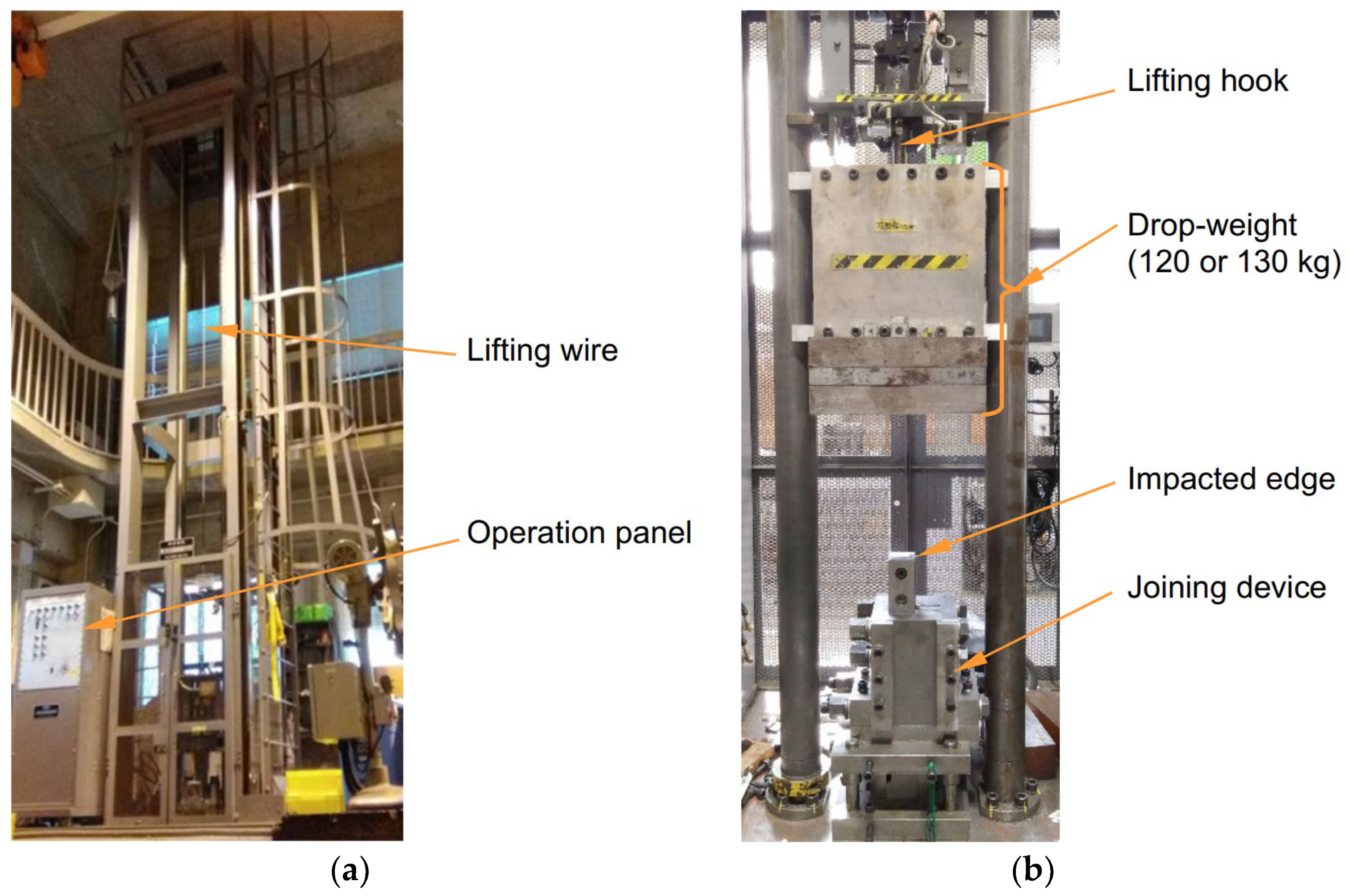
Figure 2 shows the impact testing machine with a maximum impact velocity of 10 m/s, the joining device, and the drop-weight. As shown in Figure 1a, the cross-sectional shape of the plate is a 60° tapered trapezoid with a 1 mm flat top to concentrate the plastic deformation under high pressure. The top edge of the left plate shown in Figure 1b is impacted at 10 m/s with a drop-weight to cause a sliding motion. Since the plate is wedge-shaped, where the edge lengths are 47.5 and 57.5 mm, the sliding surfaces press against each other, generating a compressive force. As a result, the high compressive stress produces a large new surface through large plastic deformation, which is a necessary part of the joining process. In the previous study, the wedge shape was shallower, where the edge lengths were 48 and 56 mm [25].
There are four holes in the holder to fix the plate with the M12 socket head cap screws; however, two holes were not used because it was found in the previous experiment that two bolts were sufficient to fix the plate [25]. The mass of the drop-weight was set to 120 or 130 kg. It should be noted that the compressive force, material deformation rate, and strain rate of the material affect the joining process, but these are not controllable experimental conditions.
The test materials were a pure copper C1100-1/4H (ultimate tensile strength: 249 MPa; 0.2% proof stress 194 MPa; plastic property: σ = 443 ε 0.25 MPa; Vickers hardness: 80 HV; and Cu > 99.9 mass %) and the aluminum alloy A6061-T6 (ultimate tensile strength: 322 MPa; 0.2% proof stress 291 MPa; plastic property: σ = 431 ε 0.08 MPa; and Vickers hardness: 107 HV). The standard chemical composition of A6061-T6 is shown in Table 1. A surface finish with #400 emery paper was applied to the 1 mm width tip part of both plates. The finishing direction is the longitudinal direction of the plate as this direction was found to be effective in the previous study [25].

3. Evaluation of Joining Performance

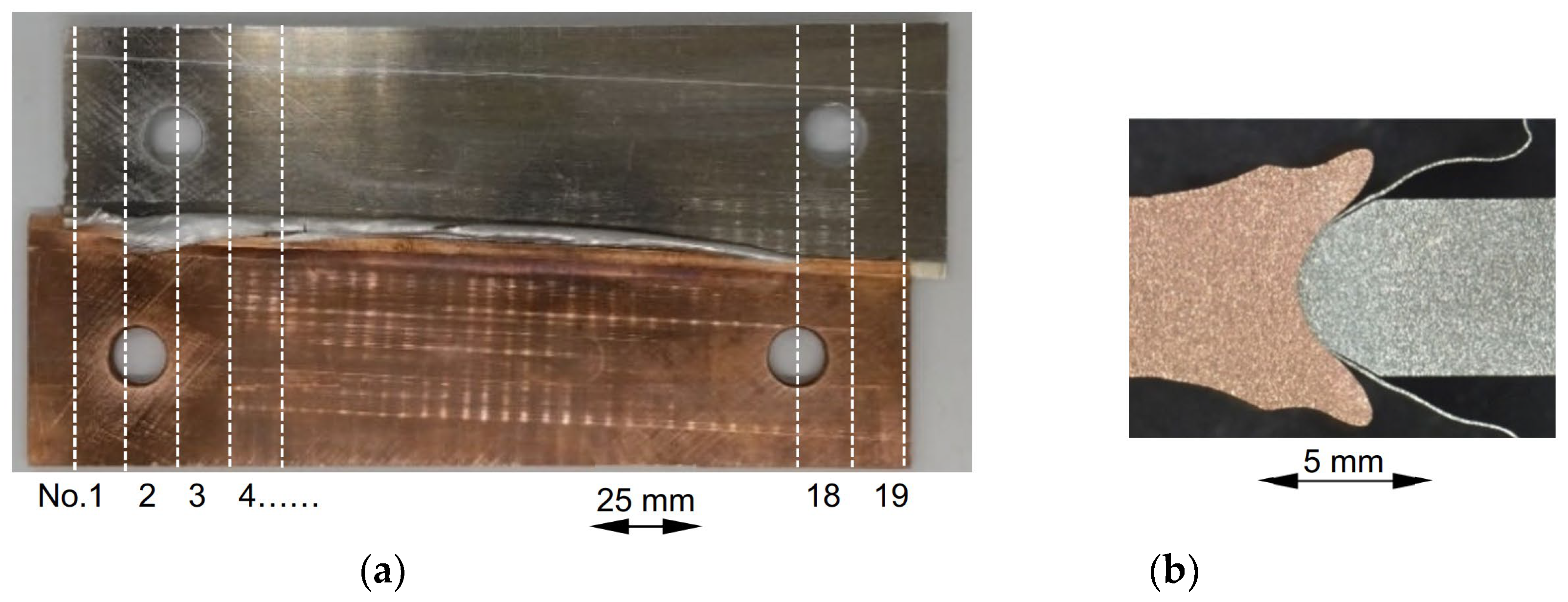
Figure 3 shows an example of the joined plates. It was cut along the dotted lines using a wire electrical discharge machine with a pitch of 10 mm to produce tensile test specimens. The distribution of joint efficiency along the joint boundary was evaluated. The joining is not achieved through the full thickness of the plate. Joint efficiency is expressed as a percentage of the strength of the weaker material when a tensile force is applied in a direction perpendicular to the boundary. The tensile test was conducted under quasistatic conditions. The joint boundary is not perfectly perpendicular to the tensile direction; however, the effect of this on the calculation is relatively small because the angle is 87.1°. Hence, it is assumed that the boundary is perpendicular to the tensile direction, and the cross-sectional area is obtained from the thickness and the width. The tensile test specimen was numbered starting from No. 1 at the left end of the photograph.
When the aluminum alloy foil is generated at the joint interface, as shown in Figure 3, the joint performance is relatively good [25]. The material was cut using a wire electrical discharge machine, resulting in a surface with a rough texture. The microscope used was a Keyence V-3000 (Osaka, Japan). The thin surface layer of A6061-T6 that comes into contact with C1100 softens due to the heat generated by the adiabatic plastic deformation of C1100 and the frictional sliding motion between the materials [26,27].

4. Results and Discussion

4.1. Effect of Wedge Dimensions of Test Plate on Joining Performance

In the author’s previous paper [25], the wedge shape of the test plate is shallower than that in this study. The mean effective stress at the joint boundary was calculated to be 695 MPa [25]. When the steeper shape was adopted, the plastic deformation of the material becomes greater under condition where the sliding stroke is comparable. The expectation is that this will result in an improvement in the performance of the joint.
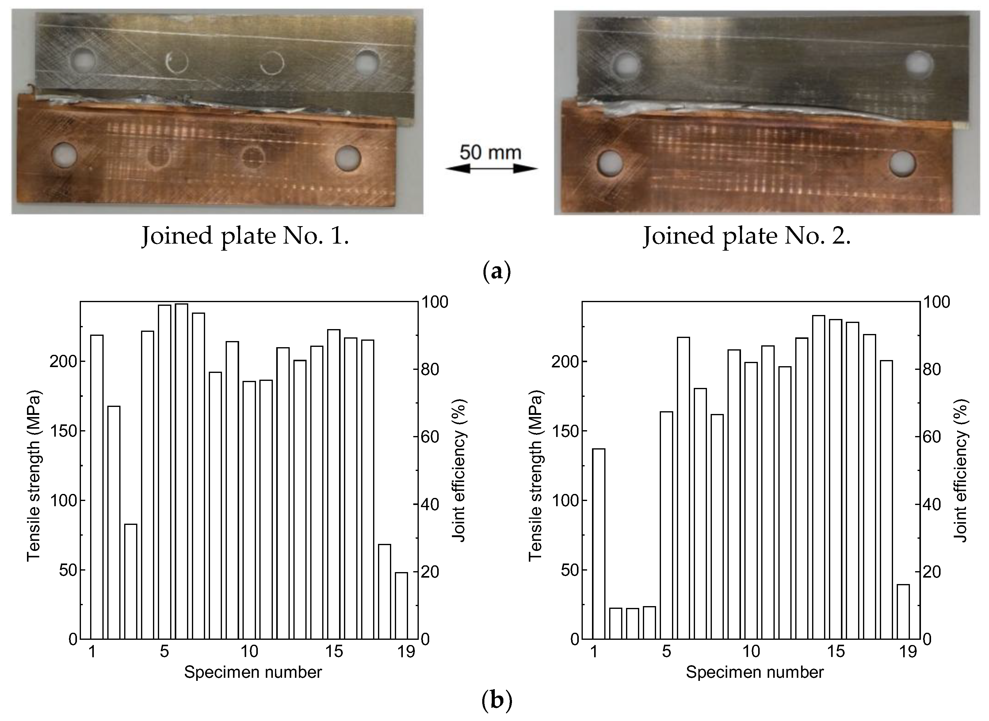
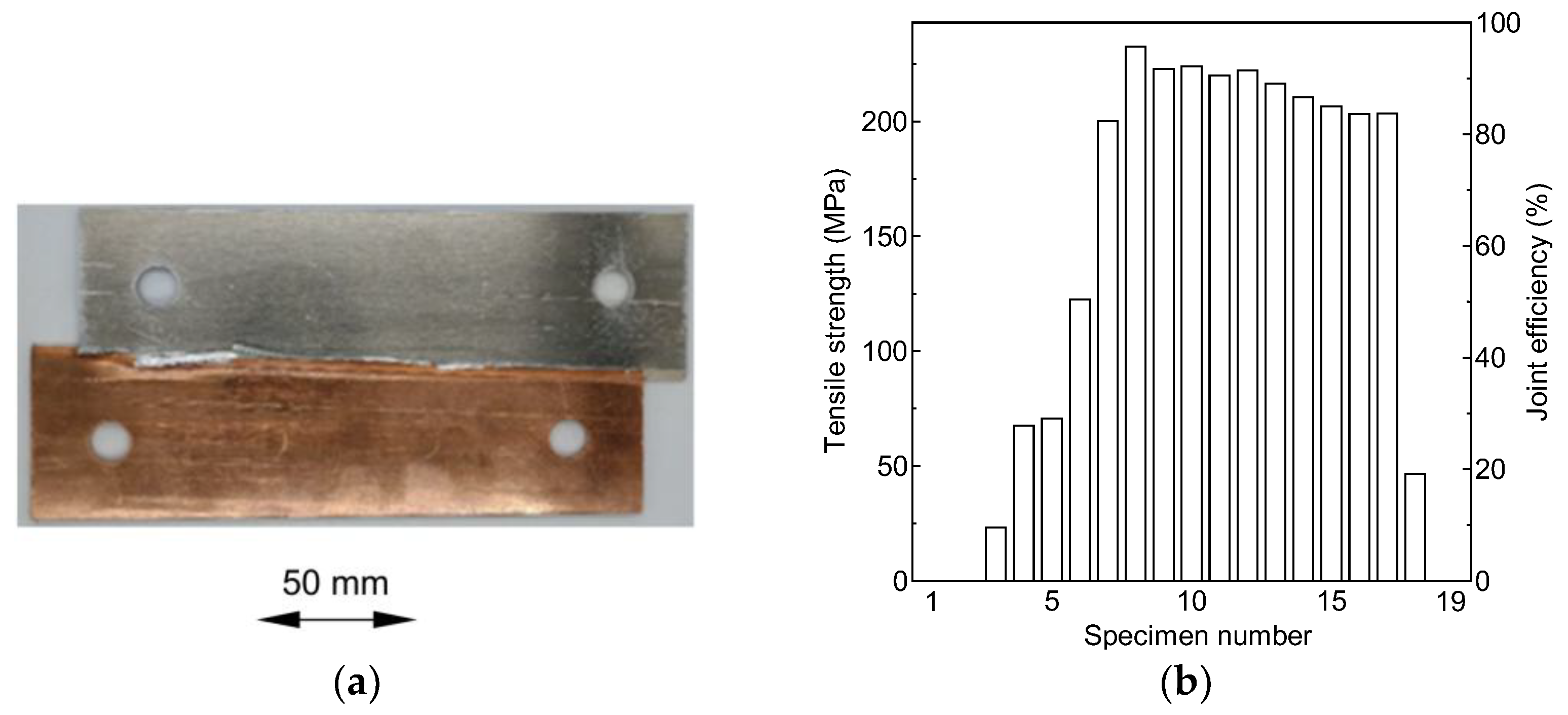
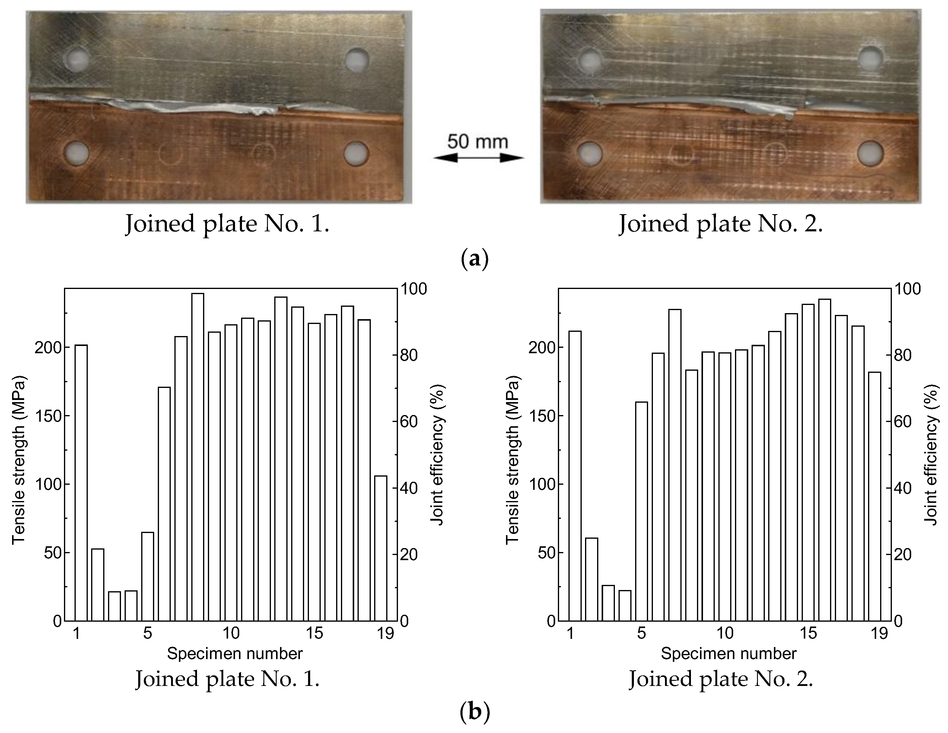
The joined plate and the distribution of the joint efficiency along the boundary are shown in Figure 4. The mass of the drop-weight was 120 kg. The same experiment was carried out twice under the same conditions to demonstrate the repeatability of the joining process. On both occasions, the sliding distance was about 92 mm. This length depends on the kinetic energy of the drop-weight and how the deformation takes place. On the other hand, Figure 5 shows the joining performance for the shallow wedge-shaped plates from the previous study [25]. The sliding distance here was about 90 mm, which is comparable to that of the cases shown in Figure 4. Comparing both results, the use of steeper wedge-shaped test plates resulted in a narrower joint boundary with a lower joint efficiency.
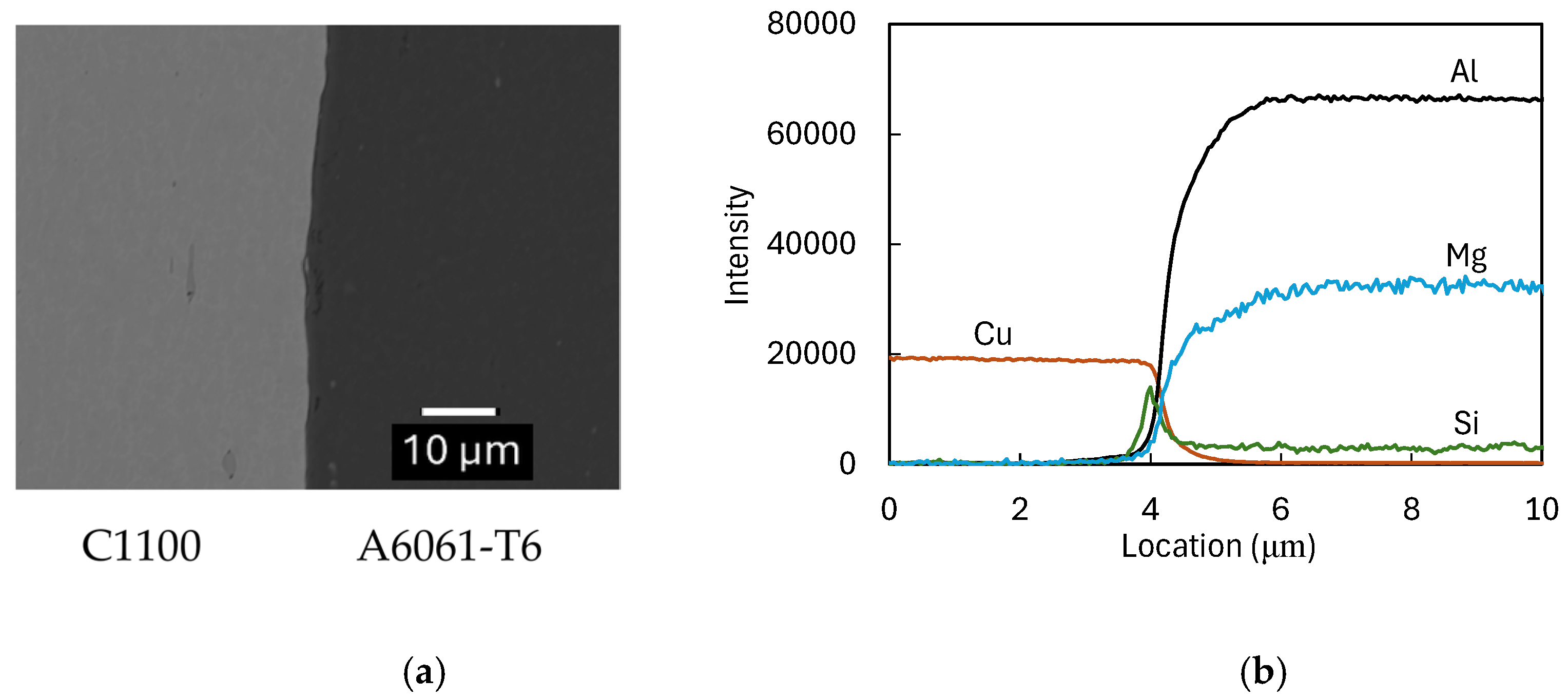
The joint boundary was analyzed using scanning electron microscopy with energy dispersive X-ray analysis (SEM-EDX), as shown in Figure 6. The SEM photograph is one reproduced from reference [25]. A thin layer whose contrast differs from both materials is observed. The intensities of Al, Cu, Mg, and Si across the joint boundary are also shown. The intensities of Mg and Si are magnified 20 times for ease of observation. The thickness of the layer is less than 2 μm. The intermetallic phase is possibly the Al-Cu system or overaged precipitates of Mg2Si.
The fracturing of the tensile test specimens in the C1100 region is demonstrated in Figure 7 for joined plate No. 1. The C1100 region is elongated, and necking is observed. Their joint efficiencies are 96.6 and 96.9%, respectively. They are effectively equal to 100%. The difference between them can probably be attributed to slight variations in the experimental conditions. The joint boundary of the other tensile specimens was fractured.
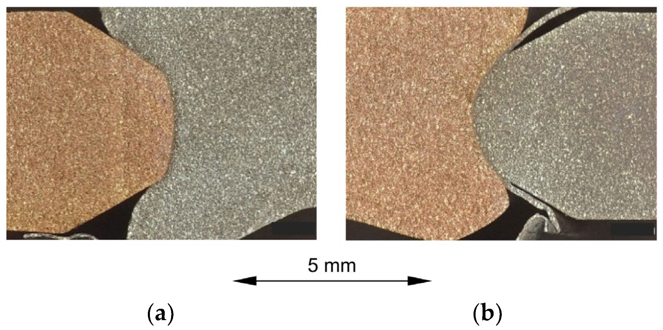
Figure 8 exhibits the joint boundaries of tensile test specimens Nos. 2 and 3 of joined plate No. 2, whose joint efficiency is shown in Figure 4b. A slight misalignment in both plates can be observed. The shape of the C1100 plate changes from convex to concave between the two specimens. The newly created surface of C1100 is not large enough to achieve joining, though the foil is generated.

4.2. Effect of Sliding Distance or Mass of Drop-Weight and Observation of Joining Process

To increase the sliding distance at the material interface, the mass of the drop-weight was increased from 120 kg to 130 kg. The joined plate and the distribution of joint efficiency are shown in Figure 9. The sliding distance is 100 mm. The joining performance did not improve significantly relative to the tests shown in Figure 4. The joint efficiency improved only in the right portion of the joined boundary. There were no specimens with fractures in the C1100 region because the alignment between the centers of plate thickness deviated due to buckling caused by excessive compression.
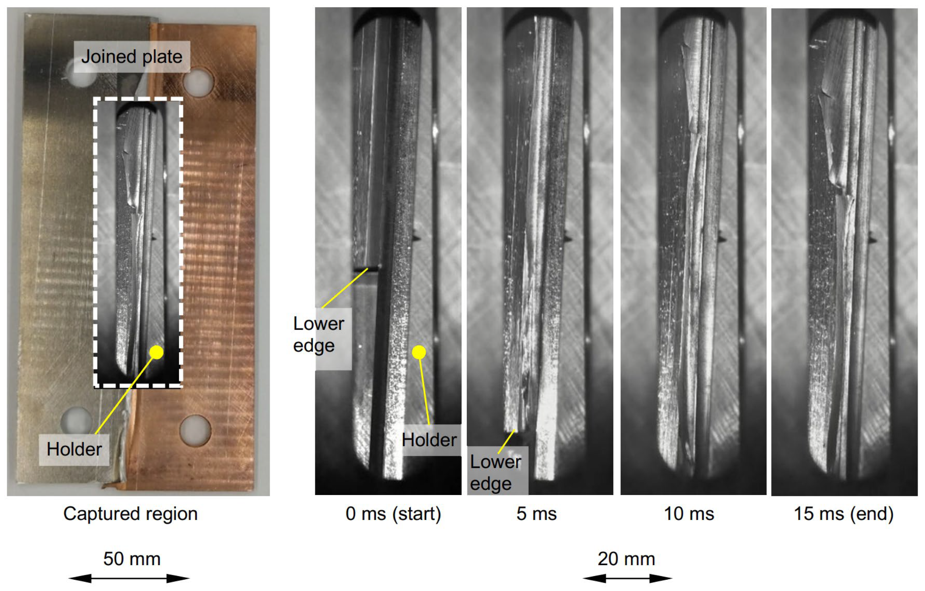
Figure 10 demonstrates the sliding motion and the generation of aluminum alloy foil during the joining process. The captured region is shown on the left side of the figure, where the left edge of the holder of the C1100 plate, which is stationary in this experiment, is visible. At the start of the test, the lower edge of the A6061 plate is positioned in the vertical center before the edge moves in a downward motion. The generation of aluminum alloy foil can already be observed at 5 ms, though the C1100 does not yet exhibit significant deformation, which begins to occur at 10 ms, where the plate’s cross-section with a 60° trapezoidal shape becomes concave along most of its length, and its thickness near the joint boundary increases. The initial speed of the drop-weight is 10 m/s, and it decelerates during the joining process. The sliding motion terminated at 15 ms, and the device vibrated for 16.6 ms.
In the previous study [25], the temperature rise in the thin surface layer of the A6061-T6 plate was calculated to be more than 250 K. After some amount of plastic deformation with frictional sliding, the yield stress of A6061-T6 becomes lower than that of C1100 and, as a result, foil is extruded by the compression. Considering that the foil is generated in the early stage of deformation, the calculated temperature may be underestimated. However, it is difficult to measure the frictional force independently of the material deformation.

4.3. Relationship Between Amount of Generated Aluminum Alloy Foil and Joint Efficiency

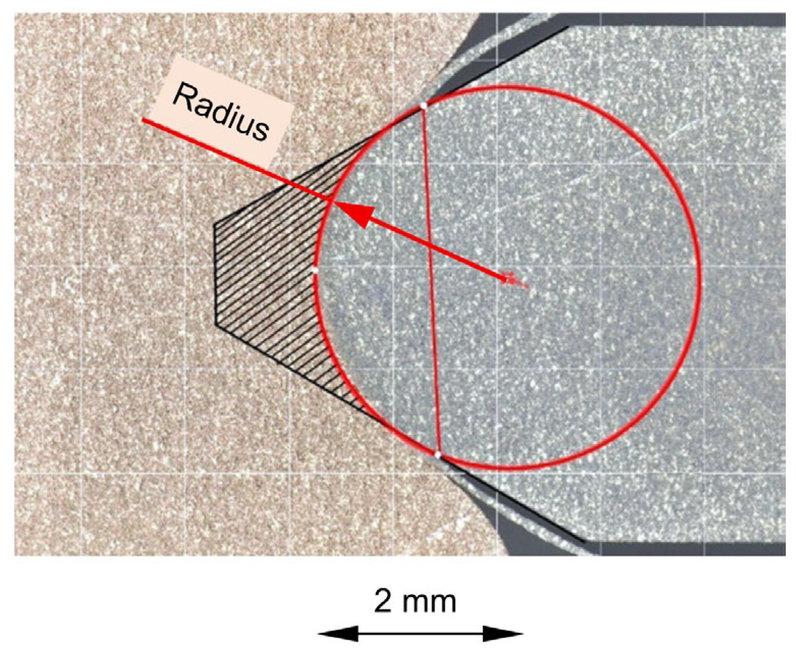
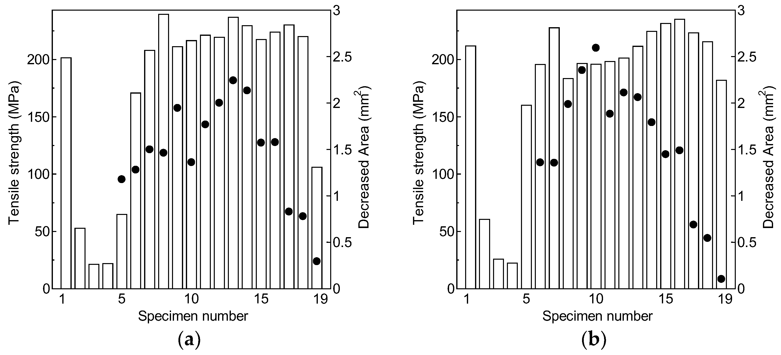
The generation of the aluminum alloy foil was earlier found to be essential for the joining process [25]. Joint efficiency may depend on the decreased cross-sectional area of A6061-T6. Hence, the decreased area was calculated by assuming that the cross-section of the joint boundary is circular, as depicted in Figure 11. In Figure 12, a decreased area is plotted with the tensile strength from the cases in Figure 9. Some areas, where the center lines of the plates are not well aligned, are not plotted.
Although the experimental conditions set for both experiments were similar, the decreased area differs even for the same location along the joint boundary. This is due to scattering and measurement errors. The decreased area is relatively small for the tensile test specimens with specimen numbers greater than 16, in which the sliding distance is relatively short—this is a feature common to both tests.
Since the A6061-T6 foil is formed soon after sliding starts, when the newly formed copper surface is large enough, the joint efficiency is high even if the sliding distance of the aluminum alloy plate is short. Joint efficiency can be high even when the actual joined area is not large because the copper near the boundary experiences large plastic deformation, resulting in significant work hardening.

4.4. Hardness Distribution near Joint Boundary

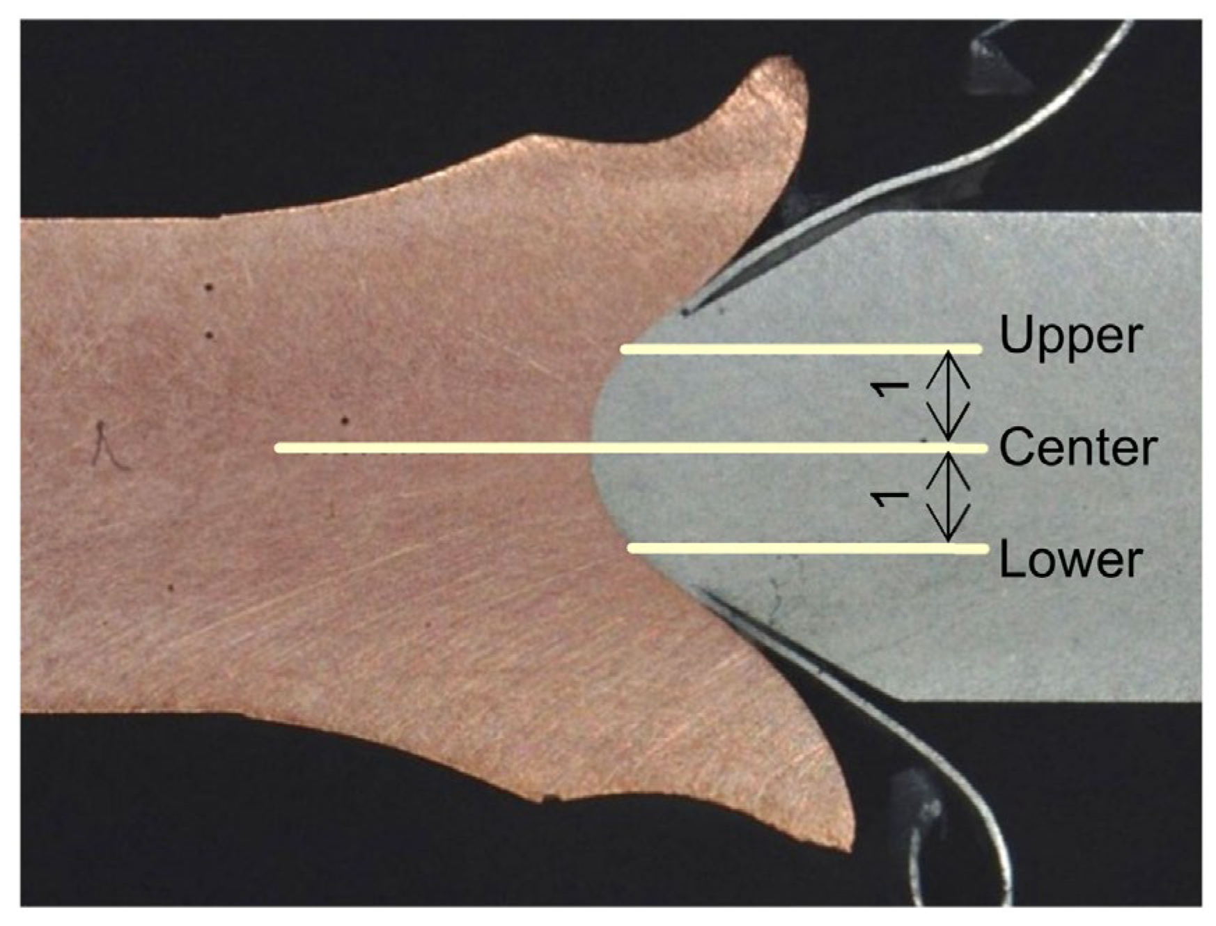
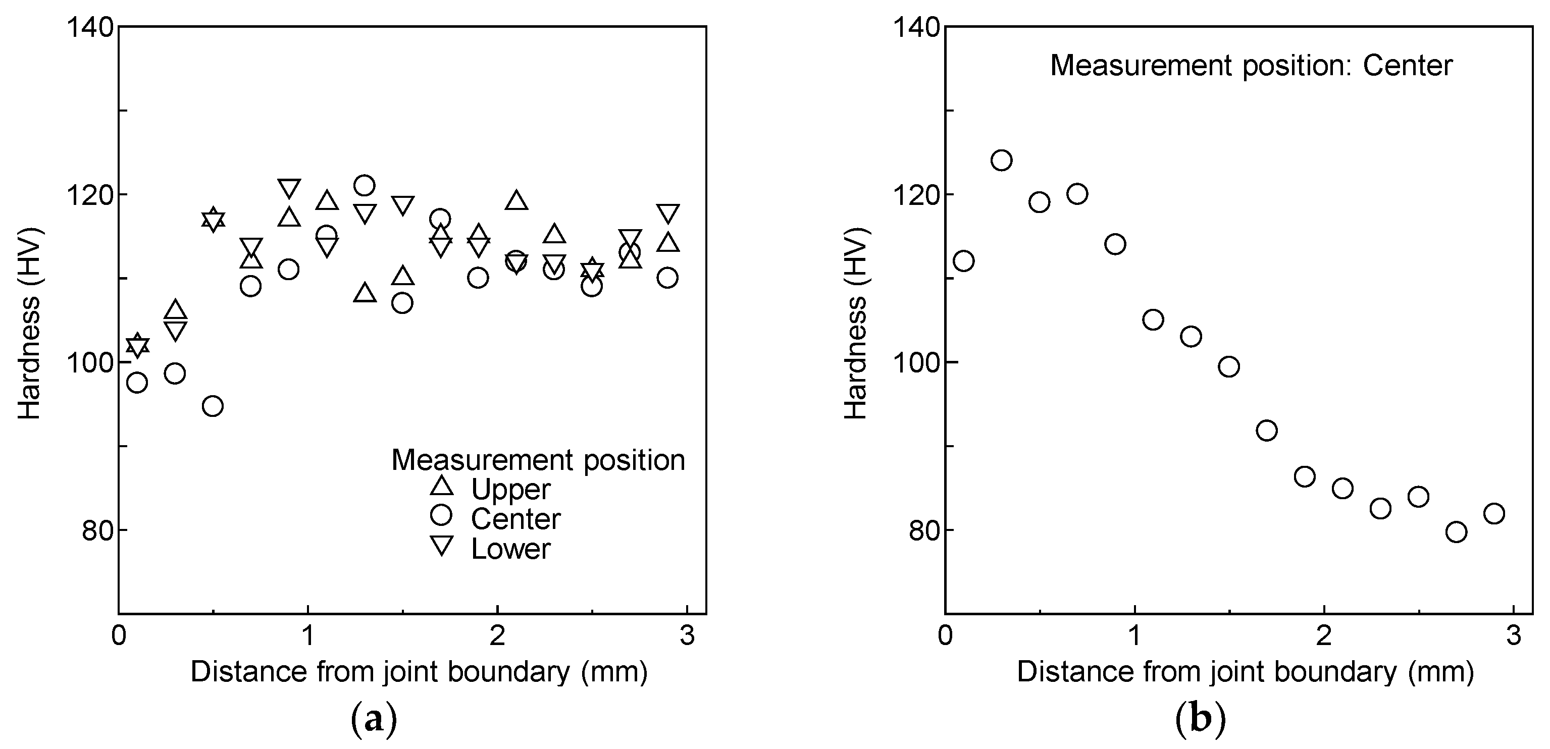
Conventional heat-based welding can be applicable to the joining of the same material combination with A6061-T6. However, this method decreases its strength significantly due to the effect of heat on the precipitation-hardened microstructure. Hence, it is worthwhile checking the changes in the material’s mechanical properties near the joint boundary, especially for A6061-T6. Vickers hardness was measured along the three lines, as described in Figure 13, and the results are plotted in Figure 14. The hardness tester used was the Mitutoyo HM-100. Before the measurement, a smooth surface was obtained using emery paper.
The Vickers hardness of A6061-T6 decreases within a narrow range of only 0.8 mm from the joint boundary, and the difference in hardness along the three measurement lines is not clear. Material softening occurs due to the temperature rise in A6061-T6 that generates the foil. The zone affected by the joining process is much smaller compared with that in heat-based welding. On the other hand, the hardness of C1100 increases about 1.5 times, with its at maximum located near the joint boundary, because of the large plastic deformation of the material. The hardness is comparable to or slightly greater than that of A6061-T6. The affected region is about 2 mm across.

4.5. Rolling of Joined Plate and Tensile Test of Rolled Sheet

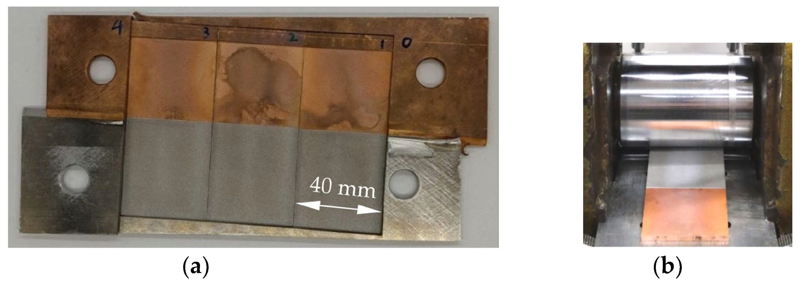
Three test plates for the rolling process were prepared from the joined plates obtained using a 120 or 130 kg drop-weight, as shown in Figure 15a. The surface layers were removed using a wire electrical discharge cutting machine because the joining was achieved in the central portion of the plate’s thickness. The thickness of the plate is 2.7 mm. The rolling operation was carried out using flat rollers with a diameter of 50 mm, as shown in Figure 15b. The reduction in the thickness was set to 0.1 mm for each pass, and the rolling operation was repeated until the thickness became 1.0 mm.
Figure 16 shows an example of the rolled sheet with its thickness reduced to 1 mm. Partial separation occurs at the edges of the joint boundary. The elastic deformation of the rollers may cause edge cracking during common cold rolling, and this has been numerically analyzed [28]. However, in the present study, the roller is relatively short. Therefore, partial separation takes place due to the difference in mechanical properties across the thickness of the plate, as well as the weak deformation constraint at the edges.
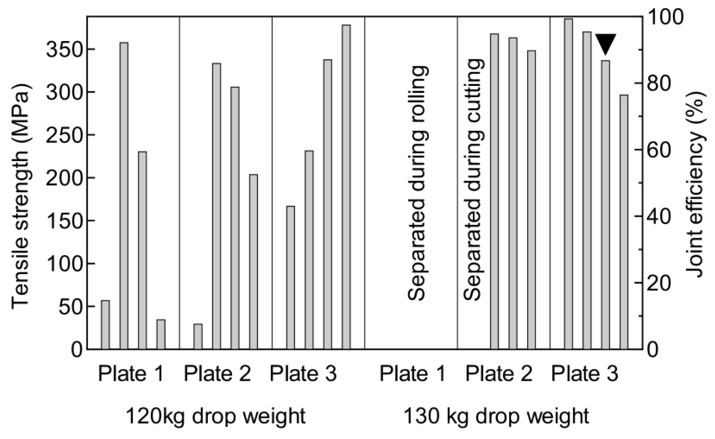
Cross-sectional profiles before and after the rolling operation are shown in Figure 17. The rounded profile before the rolling process changes to a pointed one. A tensile test was then carried out. The shape of the specimen is illustrated in Figure 18. Four specimens with a width of 10 mm were obtained from the rolled sheet with a width of 40 mm. Their tensile strengths are summarized in Figure 19. One plate obtained using the 130 kg drop-weight separated during the rolling operation, and another separated during cutting from the rolled sheet. Moreover, the strength of the rolled sheet varies remarkably.
In this graph, joint efficiency is also indicated. The strength of the base metal increases due to the rolling operation. The ultimate tensile strengths of the rolled C1100 and A6061-T6 sheet were 388 MPa and 411 MPa, respectively. Therefore, the joint efficiency was calculated using C1100’s lower strength of 388 MPa. The maximum joint efficiency obtained was 99%. When joint efficiency exceeds 80%, the main fractured region is the A6061-T6 material, as shown in Figure 20. This is probably because the hardness of C1100 becomes comparable to or marginally greater than that of A6061-T6, as demonstrated in Figure 14. When the joint efficiency is not high, fracturing occurs at the joint boundary, though the gap is not visible in the rolled sheet because compressive force is applied to the material during rolling.
In conventional welding, such as the friction welding of aluminum alloys to copper, brittle intermetallic compounds are formed at the joint interface. These significantly reduce the joint’s strength and ductility [29]. With a rolled sheet, the main region where fracturing takes place is in the A6061-T6, even though the joint boundary is subjected to a remarkably large plastic strain of ln 1 / 2.7 = 0.99 . In this regard, the SEM photograph and EDX analysis in Figure 6 indicate that the layer of the intermetallic compounds is thin enough to allow for large plastic deformation. This is a prominent feature of this joining method.

5. Conclusions

Impact butt joining of C1100 and A6061-T6 plates was investigated to show how varying the process parameters affects joint efficiency. A rolling operation was also conducted on the joined plate. The following conclusions were obtained:
  • The effect of compressive force was examined by changing the wedge shape of the test plate. The use of a steeper wedge-shape improved the joining performance significantly. Some tensile test specimens exhibited a fracture in the C1100 region.
  • The joining performance did not improve significantly even though the sliding distance increased from 90 mm to 100 mm. No tensile test specimen fractured in the C1100 region due to the misalignment between the centers of the plates caused by excessive compressive deformation.
  • Observation using a high-speed video camera during impact joining confirmed that aluminum alloy foil, the formation of which is essential to the joining process, began to form as early as just 5 ms into the test. The joining process was completed in 15 ms.
  • Measurement of Vickers hardness revealed that the hardness of A6061-T6 decreases within a very limited range of only 0.8 mm from the joint boundary. The hardness of C1100 is comparable to or slightly greater than that of A6061-T6 near the joint boundary. The affected region of C1100 is about 2 mm, which is only 40% of the plate’s thickness.
  • The joined plate was rolled until the true strain in the plate thickness reached about −1.0. A maximum joint efficiency of 99% was obtained, though statistical verification is necessary to confirm the reliability of the joint interface. When the joint efficiency was over 80%, the fracturing took place mainly in the A6061-T6 alloy.

Author Contributions

Conceptualization, M.Y.; methodology, M.Y. and Y.N.; investigation, M.Y., Y.N. and M.N.; writing—review and editing, M.Y. and M.N. All authors have read and agreed to the published version of the manuscript.

Funding

This research received no external funding.

Data Availability Statement

The original contributions presented in this study are included in the article. Further inquiries can be directed to the corresponding author.

Acknowledgments

This is a continuation of the research paper entitled “Joining of Copper and Aluminum Alloy A6061 Plates at Edges by High-Speed Sliding with Compression”, which was published in Metals 2024, 14, 878 [25].

Conflicts of Interest

The authors declare no conflicts of interest.

References

  1. Groche, P.; Wohletz, S.; Erbe, A.; Altin, A. Effect of the primary heat treatment on the bond formation in cold welding of aluminum and steel by cold forging. J. Mater. Process. Technol. 2014, 214, 2040–2048. [Google Scholar] [CrossRef]
  2. Krishna, B.V.; Venugopal, P.; Rao, K.P. Solid state joining of dissimilar sintered P/M preform tubes by simultaneous cold extrusion. Mater. Sci. Eng. A 2004, 386, 301–317. [Google Scholar] [CrossRef]
  3. Lilleby, A.; Grong, Ø.; Hemmer, H. Cold pressure welding of severely plastically deformed aluminum by divergent extrusion. Mater. Sci. Eng. A 2010, 527, 1351–1360. [Google Scholar] [CrossRef]
  4. Groche, P.; Wohletz, S.; Mann, A.; Krech, M.; Monnerjahn, V. Conjoint forming—Technologies for simultaneous forming and joining. Mater. Sci. Eng. 2016, 119, 012025. [Google Scholar] [CrossRef]
  5. Yan, H.; Lenard, J.G. A study of warm and cold roll-bonding of an aluminum alloy. Mater. Sci. Eng. A 2004, 385, 419–428. [Google Scholar] [CrossRef]
  6. Pragana, J.P.M.; Sapage, M.S.T.; Sampaio, R.F.V.; Braganca, I.M.F.; Ribeiro, I.; Silva, C.M.A.; Martins, P.A.F. Joining of hybrid busbars for E-Mobility: An economic and environmental study. J. Adv. Join. Process. 2023, 8, 100159. [Google Scholar] [CrossRef]
  7. Kaya, Y. Investigation of copper-aluminum composite materials produced by explosive welding. Metals 2018, 8, 780. [Google Scholar] [CrossRef]
  8. Seibold, M.; Schricker, K.; Bergmann, J.P. Systematic adjustment of the joining time in pulsed laser beam welding of aluminum-copper joints by means of a closed-loop control. J. Adv. Join. Process. 2022, 5, 100104. [Google Scholar] [CrossRef]
  9. Mathivanan, K.; Plapper, P. Laser welding of dissimilar copper and aluminum sheets by shaping the laser pulses. Procedia Manuf. 2019, 36, 154–162. [Google Scholar] [CrossRef]
  10. Dimatteo, V.; Ascari, A.; Liverani, E.; Fortunato, A. Experimental investigation on the effect of spot diameter on continuous-wave laser welding of copper and aluminum thin sheets for battery manufacturing. Opt. Laser Technol. 2022, 145, 107495. [Google Scholar] [CrossRef]
  11. Das, A.; Barai, A.; Masters, I.; Williams, D. Comparison of tab-to-busbar ultrasonic joints for electric vehicle Li-ion battery applications. World Electr. Veh. J. 2019, 10, 55. [Google Scholar] [CrossRef]
  12. Yang, J.; Cao, B. Investigation of resistance heat assisted ultrasonic welding of 6061 aluminum alloys to pure copper. Mater. Des. 2015, 74, 19–24. [Google Scholar] [CrossRef]
  13. Das, A.; Barai, A.; Masters, I.; Williams, D. Process robustness and strength analysis of multi-layered dissimilar joints using ultrasonic metal welding. Int. J. Adv. Manuf. Technol. 2019, 101, 881–900. [Google Scholar] [CrossRef]
  14. Hamed, A.A.; Yamagata, T.; Katoh, M.; Nishio, K.; Yamaguchi, T. Joining of A1050/A5052 and A1050/Cu by ultrasonic bonding and their materials evaluation. Q. J. Jpn. Weld. Soc. 2003, 21, 493–500. [Google Scholar] [CrossRef]
  15. Pawlicki, M.; Drenger, T.; Pieszak, M.; Borowski, J. Cold upset forging joining of ultra-fine-grained aluminum and copper. J. Mater. Process. Technol. 2015, 223, 193–202. [Google Scholar] [CrossRef]
  16. Eivani, A.R.; Mirzakoochakshirazi, H.R.; Jafarian, H.R. Investigation of joint interface and cracking mechanism of thick cladding of copper on aluminum by equal channel angular pressing (ECAP). J. Mater. Res. Technol. 2020, 9, 3394–3405. [Google Scholar] [CrossRef]
  17. Medvedev, A.E.; Lapovok, R.; Koch, E.; Höppel, H.B.; Göken, M. Optimization of interface formation by shear inclination: Example of aluminum-copper hybrid produced by ECAP with back-pressure. Mater. Des. 2018, 146, 142–151. [Google Scholar] [CrossRef]
  18. Matsumoto, R.; Hashimoto, K.; Utsunomiya, H. Improvement in bonding strength by applying circumferential sliding in cold copper/aluminum forge-bonding. J. Mater. Process. Technol. 2022, 307, 117685. [Google Scholar] [CrossRef]
  19. Yamagishi, H. Cu/Al dissimilar cold spot forge welding: Effects of bonding temperature and reduction ratio on joint strength and reaction layer growth. Metall. Mater. Trans. 2023, 54A, 3519–3536. [Google Scholar] [CrossRef]
  20. Habba, M.I.A.; Ahmed, M.M.Z. Friction stir welding of dissimilar aluminum and copper alloys: A review of strategies for enhancing joint quality. J. Adv. Join. Process. 2025, 11, 100293. [Google Scholar] [CrossRef]
  21. Celik, S.; Cakir, R. Effect of friction stir welding parameters on the mechanical and microstructure properties of the Al-Cu butt joint. Metals 2016, 6, 133. [Google Scholar] [CrossRef]
  22. Yamashita, M.; Shibuya, T.; Nikawa, M. Impact joining of metallic sheets and evaluation of its performance. Mater. Res. Proc. 2019, 13, 91–96. [Google Scholar] [CrossRef]
  23. Yamashita, M.; Iwatsuka, T.; Taguchi, H.; Nikawa, M. Impact joining of pure copper C1100 and aluminum alloy A6061-T6 plates at edges. Metals 2022, 12, 1565. [Google Scholar] [CrossRef]
  24. Yamashita, M.; Imayoshi, A.; Nikawa, M. Joining of metal plates at edges by high-speed sliding with compression. In Proceedings of the 14th International Conference on the Technology of Plasticity—Current Trends in the Technology of Plasticity, Mandelieu-La Napoule, France, 24–29 September 2023; pp. 19–26. [Google Scholar] [CrossRef]
  25. Yamashita, M.; Nishimura, Y.; Imayoshi, A.; Nikawa, M. Joining of copper and aluminum alloy A6061 plates at edges by high-speed sliding with compression. Metals 2024, 14, 878. [Google Scholar] [CrossRef]
  26. Scapin, M.; Manes, A. Behavior of Al6061-T6 alloy at different temperatures and strain-rates: Experimental characterization and material modelling. Mater. Sci. Eng. A 2018, 734, 318–328. [Google Scholar] [CrossRef]
  27. Ogar, P.; Ugryumov, E.; Koryakyn, I. The Influence of the mechanical properties of copper at elevated temperatures on the tightness of the sealing joint. Mater. Today Proc. 2021, 38, 1764–1768. [Google Scholar] [CrossRef]
  28. Roh, Y.; Byon, M.; Lee, Y. Numerical analysis of edge cracking in high-silicon steel during cold rolling with 3D fracture locus. Appl. Sci. 2021, 11, 8408. [Google Scholar] [CrossRef]
  29. Pan, L.; Li, P.; Hao, X.; Zhou, J.; Dong, H. Inhomogeneity of microstructure and mechanical properties in radial direction of aluminum/copper friction welded joints. J. Mater. Process. Technol. 2018, 255, 308–318. [Google Scholar] [CrossRef]
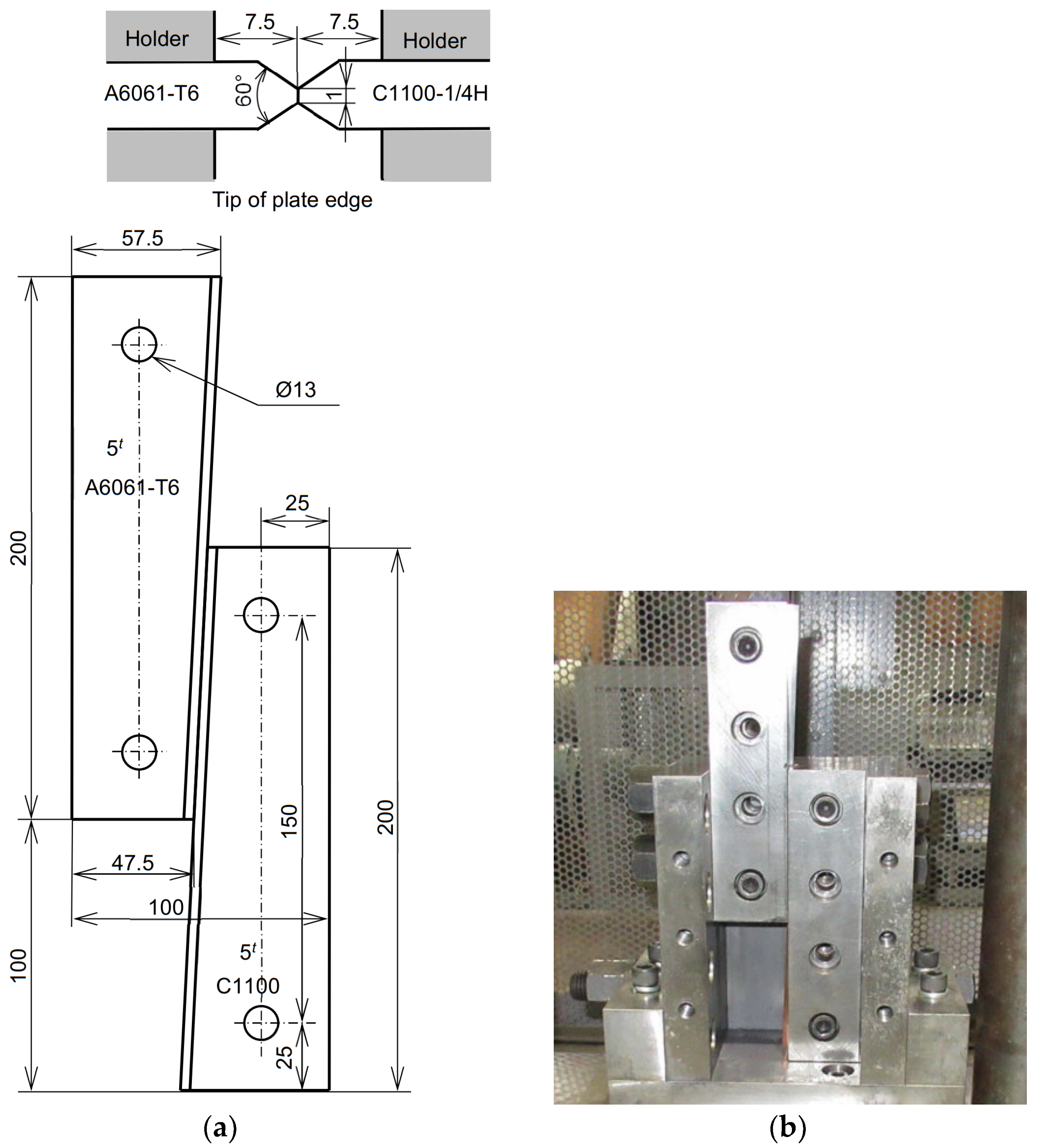
Figure 1. Test plates and setting in device: (a) schematic of wedge-shaped plate; (b) initial configuration of plates fixed to holders in joining device (with front components removed).
Metals 15 01207 g001
Figure 2. Impact testing machine and testing part: (a) general view of drop-weight impact testing machine; (b) joining device and drop-weight.
Metals 15 01207 g002
Figure 3. Joined plate and cross-section of joint boundary (120 kg drop-weight): (a) the joined plate with cutting lines and specimen numbers for the tensile test; (b) an example of the cross-section of the joint boundary.
Metals 15 01207 g003
Figure 4. Joined plate and joining performance obtained using 120 kg drop-weight: (a) joined plate; (b) tensile strength and joint efficiency along the joint boundary.
Metals 15 01207 g004
Figure 5. Joining performance of shallower wedge-shaped specimen [25] (edge length: 48 and 56 mm): (a) joined plate; (b) tensile strength and joint efficiency.
Metals 15 01207 g005
Figure 6. Magnified photograph and element analysis near joint boundary: (a) backscattered electron image [25]; (b) intensities of Cu, Al, Mg, and Si in elemental analysis.
Metals 15 01207 g006
Figure 7. Fractured specimens in C1100 region of joined plate No. 1 from Figure 4: (a) tensile test specimen No. 5; (b) tensile test specimen No. 6.
Metals 15 01207 g007
Figure 8. Cross-section of joint boundary of tensile test specimen of joined plate No. 2 shown in Figure 4b: (a) convex shape of C1100 tip of tensile test specimen No. 2; (b) concave shape of C1100 tip of tensile test specimen No. 3.
Metals 15 01207 g008
Figure 9. Joined plate and joining performance obtained using 130 kg drop-weight: (a) joined plate; (b) tensile strength and joint efficiency.
Metals 15 01207 g009
Figure 10. Joining process observed with high-speed video camera (left: A6061-T6; right: C1100; mass of drop-weight: 130 kg).
Metals 15 01207 g010
Figure 11. Decreased cross-sectional area of A6061-T6 due to sliding motion with compression.
Metals 15 01207 g011
Figure 12. Decreased cross-sectional area of A6061-T6 (dots) and tensile strength for the cases in Figure 8: (a) joined plate No. 1; (b) joined plate No. 2.
Metals 15 01207 g012
Figure 13. Measurement positions of Vickers hardness tests.
Metals 15 01207 g013
Figure 14. Vickers hardness distribution near the joint boundary of tensile test specimen No. 5 of joined plate No. 2 (ref. Figure 4): (a) A6061-T6; (b) C1100.
Metals 15 01207 g014
Figure 15. Rolling of joined plates: (a) three plates cut from joined plate (t = 2.7 mm, w = 40 mm); (b) rolling operation of joined plate.
Metals 15 01207 g015
Figure 16. Example of rolled sheet.
Metals 15 01207 g016
Figure 17. Change in cross-sectional profile of joint boundary: (a) before rolling; (b) after rolling.
Metals 15 01207 g017
Figure 18. Rolled sheet tensile test specimen.
Metals 15 01207 g018
Figure 19. Tensile strength of rolled sheet (initial thickness: 2.7 mm; final thickness: 1.0 mm).
Metals 15 01207 g019
Figure 20. Fractured specimen in rolled sheet tensile test (mark ▼ in Figure 19): (a) general view; (b) cross-sectional view of both sides.
Metals 15 01207 g020
Table 1. Chemical compositions of A6061-T6 (mass %).
SiFeCuMnMgCrZnAl
0.40~0.8Max. 0.700.15~0.40Max. 0.150.8~1.20.04~0.35Max. 0.25Bal.
Disclaimer/Publisher’s Note: The statements, opinions and data contained in all publications are solely those of the individual author(s) and contributor(s) and not of MDPI and/or the editor(s). MDPI and/or the editor(s) disclaim responsibility for any injury to people or property resulting from any ideas, methods, instructions or products referred to in the content.