Abstract
In the hot strip rolling process, inter-stand speed coordination directly affects product quality and production stability. Traditional linear speed compensation strategies perform poorly under extreme conditions such as strip tension and strip piling, making it difficult to maintain stable loop control. This study proposes a speed compensation strategy that integrates Particle Swarm Optimization (PSO) with Model Predictive Control (MPC). Based on the mechanism of hot rolling, a nonlinear state-space model is constructed, in which the compensation parameter is treated as an optimization variable to formulate a rolling optimization problem. PSO is employed to globally solve the nonlinear MPC problem, yielding an optimal compensation sequence that adapts to disturbance variations. The proposed algorithm can adaptively adjust the speed compensation parameter under typical strip piling and strip tension conditions, thereby achieving stable loop regulation and maintaining the looper angle within the desired range. This effectively addresses the speed coordination problem under abnormal conditions in hot strip rolling, improving the control performance. The experimental results verify the effectiveness of the proposed method.
1. Introduction
Hot strip rolling is one of the most critical processes in modern steel manufacturing, and its production efficiency and product quality directly impact the economic benefits and competitiveness of steel enterprises [1]. In this process, speed coordination between stands is crucial, particularly for the stable operation of the looper system, which is responsible for buffering speed fluctuations and coordinating the rolling rhythm [2,3,4]. During hot strip rolling, speed mismatch between adjacent stands can create asymmetrical conditions, leading to uneven deformation of the strip. Such asymmetry may cause the strip to bend toward one work roll, resulting in poor shape and profile deviations [5]. Equally, stable looper tension dynamics ensure safe production. Improper coordination may trigger severe disturbances such as equipment vibration or cobbling, leading to production interruptions [6]. Thus, stable control of the looper angle through coordinated speed adjustment is essential for process stability.
In practical hot strip rolling, abnormal looper angle deviations mainly manifest as two typical conditions: “strip tension” and “strip piling”. Strip tension refers to a continuous decrease in the looper angle, which may even approach zero, usually indicating that the speed of the preceding stand is too high, causing the strip to become excessively thin. Strip piling is characterized by an increasing looper angle and the accumulation of strip material at the looper, often caused by excessive speed of the following stand or insufficient deceleration of the preceding stand. Both of these abnormalities disrupt the tension balance between stands, affecting the accuracy of thickness control and potentially leading to equipment vibrations or even shutdowns [7,8,9]. Therefore, achieving stable control of the looper angle is essential for ensuring the efficient and stable operation of the hot strip rolling process.
1.1. Background of Analysis
The looper system plays a pivotal role in coordinating the speeds of adjacent stands and buffering thickness fluctuations, with its dynamic behavior directly influencing the stability of the inter-stand tension [10,11,12]. Consequently, existing research has primarily focused on controlling the looper angle to enhance system stability and improve strip thickness accuracy. Ref. [13] investigated an innovative guaranteed-cost sliding mode control method to improve the control accuracy of systems with uncertain looper tension in hot strip finishing mills. Ref. [14] studied the looper tension control problem in hot rolling mills, focusing on the instability of tension caused by slip uncertainties that affect strip thickness precision. An adaptive PI controller was proposed to mitigate the effects of slip uncertainty, achieving a satisfactory looper tension control performance. Ref. [15] proposed a dynamic matrix predictive control method for multivariable hydraulic looper systems, which outperformed traditional controllers under model mismatch conditions and effectively enhanced strip quality and control performance. Ref. [16] presented an control method based on a discrete-time model for looper tension system state feedback, where the system was approximated in discrete form, and an control law was designed using Lyapunov function techniques.
A fundamental prerequisite for effective looper system control is the establishment of an accurate and physically interpretable rolling process model. In the looper system, strong nonlinear coupling exists among mechanical motion, inter-stand thickness, and strip tension; thus, precise mathematical modeling is essential for controller design and performance evaluation. Although existing studies have developed relatively detailed physical models of looper systems, these models primarily capture mechanical and dynamic characteristics without incorporating the concept of active compensation. As a result, their applicability remains limited when designing control strategies capable of actively addressing abnormal conditions such as strip tension and strip piling. Ref. [17] provided a detailed description of the geometric structure of the looper system, characterizing the relationship between looper angle and looper tension based on geometric principles and presenting clear mathematical formulations. Ref. [18] proposed and validated a one-dimensional dynamic model of a hot strip finishing mill suitable for looper control analysis, demonstrating good scalability for other control and analysis tasks. Ref. [19] constructed a physical model of the hot strip looper system and, based on this model, proposed multiple control strategies that significantly improved the system performance, verifying the effectiveness of model-based control approaches in hot strip looper systems. However, systematic studies on active compensation mechanisms for typical abnormal conditions, such as strip tension and strip piling, are still lacking.
In practice, both strip tension and strip piling essentially manifest as persistent deviations in the looper angle in opposite directions. When stand speeds are adjusted according to fixed rules under such conditions, the abnormal state can be further aggravated. Therefore, beyond traditional controller designs, control frameworks based on active compensation are expected to identify and mitigate these abnormal conditions more effectively, thereby improving system robustness and operational stability. Ref. [20] proposed an active compensation method for periodic disturbances caused by roller eccentricity in rolling mills, integrating it into automatic thickness control systems to improve thickness tolerance. Ref. [21] introduced an active vibration suppression method based on disturbance estimation and compensation algorithms, addressing issues such as uneven plate thickness and equipment wear induced by mill vibration. Ref. [22] presented an online shape compensation method based on rolling load and torque monitoring to estimate shape defects and adjust mold compensation accordingly.
Inspired by recent studies on system identification and control under constrained or adversarial information environments, such as binary-valued observations and cyber-attacked communication channels [23,24,25,26], this work extends the idea of modeling precision and robustness into the hot strip looper control field. These studies demonstrate that accurate system modeling and identification remain feasible even under limited or tampered data conditions, providing valuable insight for developing control strategies that can actively compensate for abnormal process disturbances in complex industrial systems. With the continuous development of advanced algorithms, an increasing number of emerging control paradigms have been introduced, enabling more effective realization of active compensation strategies. Ref. [27] proposed a neural network model predictive control method combined with process monitoring to address product quality stabilization under abnormal industrial conditions, demonstrating the effectiveness of data-driven predictive control. Ref. [28] introduced a pass design method based on reinforcement learning and an analytical rolling model to ensure the mechanical properties of the final product. By combining a physical strengthening model with an analytical rolling model, this approach tracks microstructural evolution during rolling and predicts yield and tensile strength. Ref. [29] presented a plate shape recognition method for the roller cooling process, combining the global optimization capability of PSO with the descriptive power of Gaussian functions to capture shape defects better. Ref. [30] developed a hybrid model for the design and control of a continuous dry granulation process, facilitating the implementation of nonlinear model predictive control (NMPC) in the Alexanderwerk WP120 roller compactor. Ref. [31] proposed a PSO-NMPC control strategy that integrates the PSO algorithm into the NMPC controller to enhance the path tracking performance of underground Load-Haul-Dump (LHD) vehicles. Both refs. [30,31] demonstrated that the proposed control approaches possess practical engineering applicability.
Building upon the existing literature, although various control methods have been developed, there remains a significant gap in active compensation mechanisms for abnormal conditions such as strip tension and strip piling. Traditional control schemes often rely on fixed rules for speed adjustment or parameter tuning, making them difficult to adapt to dynamic variations in rolling conditions.
1.2. Contributions
This paper proposes a looper angle control method based on a speed compensation approach to address the two common extreme abnormal scenarios, strip tension and strip piling, during hot strip rolling. First, based on the physical mechanisms of hot strip rolling, a representative nonlinear state-space model is constructed by introducing a speed compensation parameter, integrating the looper set equation, strip thickness equation, and flow equation. Subsequently, the Model Predictive Control (MPC) strategy combined with Particle Swarm Optimization (PSO) is designed: MPC is used to formulate the nonlinear optimization problem under looper angle control, and PSO is employed to solve for the optimal speed compensation parameter sequence, achieving active control under dynamic conditions. Finally, numerical simulation experiments validate the effectiveness of the proposed control method in handling strip tension and strip piling abnormal scenarios, confirming that the introduction of the speed compensation parameter significantly improves the system’s operational stability and control performance.
The main objective of this paper is to achieve stable looper angle control in hot strip rolling under abnormal conditions such as strip tension and strip piling through a speed compensation strategy that integrates PSO with MPC. Based on this objective, the following research questions are formulated: RQ1: What are the fundamental mechanisms leading to strip tension and strip piling, and how can these abnormal conditions be theoretically prevented from the perspective of looper angle deviation and inter-stand speed mismatch? RQ2: How can a nonlinear state-space model of the looper and the inter-stand system be constructed with a dynamic compensation parameter, providing a physically interpretable foundation for control algorithm design? RQ3: How can the control algorithm be designed to achieve real-time optimization of the speed compensation parameter?
The main innovations and contributions of this paper are as follows:
- Existing research on looper angle control in hot strip rolling rarely addresses extreme scenarios such as strip tension and strip piling. This study proposes an active compensation control method based on speed compensation and investigates its performance under both strip tension and strip piling scenarios.
- By integrating the rolling mechanism of hot strip rolling, a nonlinear state-space model incorporating a speed compensation parameter is established, which describes the complex nonlinear relationship between the looper angle and the rolling speeds, thereby providing a mathematical foundation for the subsequent control algorithm design.
- A combined MPC–PSO strategy is adopted to formulate a nonlinear optimization problem for the hot strip rolling process, where the PSO algorithm is employed to obtain the optimal sequence of compensation parameters for dynamic adjustment during the control process.
The remainder of this paper is organized as follows: Section 2 introduces the two abnormal scenarios, strip tension and strip piling, and presents the proposed speed compensation based solution. Section 3 develops a nonlinear state-space model incorporating the speed compensation parameter based on the hot strip rolling mechanism. Section 4 applies MPC to formulating the looper angle optimization problem based on the aforementioned nonlinear model and employs the PSO algorithm to solve it. Section 5 presents numerical simulation experiments to verify the effectiveness of the proposed method. Section 6 summarizes the main findings of this work.
2. Problem Formulation
In the hot strip rolling process, maintaining the stability of the inter-stand strip tension is crucial. When the roll gap of the -th stand changes by , the thickness of the rolled material will undergo a corresponding change. Based on the mass flow conservation principle between two adjacent stands, the speed change in the i-th stand is proportional to the change in the roll gap of the -th stand, denoted as .
This relationship represents the traditional speed compensation model, which can maintain the stability of the strip tension to some extent. However, in actual production, this linear compensation mechanism has significant drawbacks. Specifically, when the loop length between adjacent stands is very small, the system is prone to strip tension. Conversely, when the loop length is too large, strip piling may occur. For example, when between the i-th stand and the -th stand is very small, severe strip tension problems can occur. In such cases, if the roll gap of the -th stand is reduced, the traditional model suggests that the speed should decrease. However, this would exacerbate the strip tension, and the correct approach should be to stop compensating for the speed. Similarly, when is large, leading to severe strip piling, if the roll gap of the -th stand is increased, the traditional model suggests speeding up . However, this would worsen the strip piling, and the correct approach should again be to stop compensating for the speed. Therefore, the traditional linear compensation model is not applicable in these extreme scenarios.
To avoid these situations, a weighted compensation strategy has been proposed, where a speed compensation parameter k is introduced to modify the speed compensation model:
where k is adjusted based on the deviation of the current looper angle from the reference looper angle , with the traditional compensation rules shown in Table 1.

Table 1.
Traditional speed compensation rule.
Although this rule alleviates strip tension and strip piling problems to some extent, it is based on manual experience and lacks sufficient responsiveness to the complex variations on site. As a result, unreasonable compensation may still occur under different production scenarios. Therefore, the core problem addressed in this paper is how to intelligently determine the compensation parameter k based on the system’s current state in order to achieve reasonable compensation for the speed of the i-th stand, thereby stabilizing the looper angle within the target range and preventing the occurrence of strip tension and strip piling scenarios.
3. Model Construction
To achieve intelligent compensation for the stand speeds, a model-based approach is essential. This section details the modeling of the three core physical processes critical to inter-stand tension and mass flow control and constructs mathematical formulations explicitly designed for the subsequent control algorithm.
- The looper length model: The primary relationship between the measurable looper angle and the unmeasurable looper length L is a fundamental geometric process. Starting from the exact geometric equation, a simplified third-order polynomial model is derived.
- An incremental model based on the speed compensation parameter: The core of speed compensation lies in governing the mass flow balance under abnormal conditions. Based on the principle of mass flow conservation and rolling deformation mechanics, an incremental speed–thickness model is developed. Crucially, a speed compensation parameter k is introduced, transforming the physical relationship into a tunable control input. The resulting incremental model is inherently discrete-time, aligning directly with digital control system requirements.
- Nonlinear state-space model construction: To provide a comprehensive foundation for advanced control algorithms, the aforementioned physical relationships are integrated into a nonlinear state-space model. This formulation is specifically constructed for algorithm design, enabling the prediction of system states and the calculation of optimal control actions.
The main physical quantities, their symbols, meanings, and units used in this paper are summarized in Table 2:
Table 2.
Main physical quantities.
3.1. Looper Length Model
In the hot strip rolling process, the looper length is one of the key parameters that affect the rolling rhythm coordination and product quality. However, due to the constraints of on-site conditions, the looper length cannot be directly measured and is usually inferred indirectly through its geometric relationship with the looper angle. Therefore, the model needs to balance accuracy and implementation complexity to ensure the stability of the control system and the reliability of the inferred results. The geometric relationship between looper length variation and looper angle is shown in Figure 1.
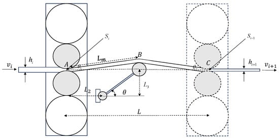
Figure 1.
The geometric structure of the looper system.
In the figure, r is the roll radius in meters; represents the distance between two adjacent stands in meters; is the length of the hydraulic looper arm in meters; is the distance from the looper support point to the upstream stand in meters; and is the height from the looper support point to the rolling plane in meters.
The relationship between looper length and looper angle is given as follows:
However, in practical engineering applications, such expressions are too complex. Therefore, the variation in looper length is approximated and regressed against the looper angle, yielding the following mapping function :
where are the fitting coefficients between the looper length and looper angle. Figure 2 shows the regression curve of the relationship between the looper angle and the looper length L in the actual hot strip rolling production line.
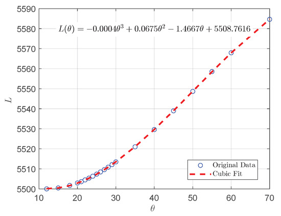
Figure 2.
Relationship between looper angle and looper length.
3.2. Incremental Model Based on Speed Compensation Parameter
In the hot strip rolling process, to ensure rolling stability, it is necessary to maintain close speed coordination between multiple stands. Especially when the downstream stand (stand ) adjusts its roll gap, the exit strip thickness will change, which will result in looper length variation. If the upstream stand (stand i) speed is not adjusted in time, issues such as strip tension or strip piling can occur. Therefore, a speed compensation mechanism must be introduced to quickly respond to these changes.
When the roll gap of stand changes by , the exit strip thickness will also change. According to the theory of rolling deformation mechanics, the thickness change can be approximated as
Let , and combined with (4), we find that
Similarly, the incremental model for the strip thickness at stand i can be expressed as
Based on the mass flow conservation principle for a single stand, the following equation holds:
By combining with (5), it is clear that
For mass flow conservation between two stands, it follows that:
From this, the speed change in stand i, , is derived by
Equation (10) shows that to maintain material flow continuity, the speed of stand i must be dynamically adjusted to accommodate downstream thickness changes. Mismatched speeds will directly impact looper length changes, which in turn affect the looper angle . The length of the strip produced by stand i per unit time is , while the throughput length of stand is . The difference between these two is the instantaneous variation rate of looper length. Accumulated over time, it is given that
From (14), we obtain
To improve system stability and adaptability, a speed compensation parameter k is commonly introduced in practical applications, leading to the speed compensation model:
where k is a proportional parameter that reflects the system’s adjusted magnitude and the direction of the speed compensation response due to thickness disturbances.
3.3. Nonlinear State-Space Model Construction
This section constructs the nonlinear state-space model of the system based on rolling physics principles, which will serve as the foundation for the subsequent compensation parameter k control design.
Consider the system between the i-th and -th stands, and construct the following nonlinear state-space model with the looper angle and looper length as outputs:
where the state , input , and output are defined as follows:
4. PSO-MPC-Based Speed Compensation Algorithm for Hot Strip Rolling
In this section, based on the nonlinear state-space model established in the previous section, a PSO-supported MPC algorithm is designed to achieve stable control and dynamic coordination of the looper angle during the hot strip rolling process. The algorithm treats the speed compensation parameter k as an optimization variable, solving the rolling optimization problem globally using the PSO algorithm at each control cycle to determine the optimal compensation that brings the predicted output as close as possible to the target, effectively avoiding rolling abnormalities such as strip tension or strip piling.
PSO-MPC is a control strategy that integrates predictive control principles with swarm intelligence optimization, making it especially suitable for industrial dynamic process control, which involves complex nonlinear modeling and constraint handling. The core idea is to predict the system’s evolution over a future time horizon, based on the current system state and known disturbances, using the system model. The PSO algorithm is then used to search for an optimal control sequence that minimizes the error between the predicted output and target while satisfying the system constraints. Afterward, only the first control input for the current time step is applied, and the process is repeated in the next control cycle, forming a rolling optimization feedback control mechanism, as shown in Figure 3.
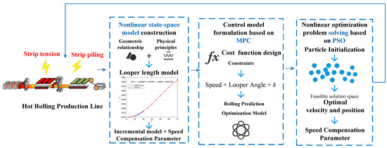
Figure 3.
Algorithm framework.
Therefore, the PSO-MPC control strategy not only can accurately adapt to the dynamic characteristics of the hot strip rolling system but also can provide a stable, controllable, and globally optimized compensation control solution in high-dimensional nonlinear space, laying a solid foundation for real-time optimization and adjustment of the intelligent rolling process.
4.1. Control Model Formulation Based on MPC
Based on the nonlinear state-space model in (15), the core of the MPC problem formulation is to transform the control objective, i.e., looper angle stability, into a cost function, while explicitly considering system constraints. Let the rolling optimization time horizon be , and the objective is to make the looper angle for the next steps as close as possible to the reference value . We further introduce a speed penalty term to ensure that the control variables remain within acceptable bounds and to avoid large, unstable speed, thus constructing the following constrained cost function:
where represents the i step prediction output based on the current system state at time t, is the speed boundary penalty coefficient, and are the acceptable speed limits.
The optimization variable for MPC is the compensation parameter sequence . To ensure that the speed adjustments during rolling remain within a reasonable range, the following constraints are imposed on the control variables:
Additionally, considering the strong coupling between the looper angle and the loop length , and to prevent the system from entering dangerous states such as strip tension or strip piling, hard constraints are set for the angle range:
To characterize the multi-step prediction process of MPC within the rolling time horizon, based on (17) and (18), considering the nonlinear state transition function and the output mapping , the recursive expressions for the predicted state and output are as follows:
Therefore, the control problem can be formulated as a nonlinear optimization problem:
4.2. Nonlinear Optimization Problem Solving Based on PSO
To solve the nonlinear MPC optimization problem (23) established in the previous section, this study adopts PSO as the solver. Compared to traditional gradient-based methods, PSO has advantages such as not relying on gradient information, ease of implementation, and fast convergence, making it especially suitable for optimization and control scenarios with strong coupling and highly nonlinear models, such as the hot rolling process. PSO is a swarm intelligence algorithm that simulates the foraging behavior of birds, where particles interact and cooperate to search for the optimal solution. In this study, each particle is encoded as a compensation factor sequence, denoted as :
where represents the position of particle j in generation g, i.e., a candidate compensation factor sequence, which is an estimate of the optimal control sequence in the nonlinear MPC problem.
The objective of the particles is to find an optimal compensation sequence that minimizes the cost function (19). Each particle in PSO has the following attributes:
- The position vector represents the compensation factor sequence of particle j at generation g, i.e., the current solution;
- The velocity vector controls the search direction and amplitude of the particle;
- The personal best position is the position of the particle with the smallest cost function value in its history;
- The global best position is the best solution found among all particles so far.
The update rule for each particle is as follows:
where is the inertia weight, which balances the search ability and convergence speed of the particle; are the learning factors for the individual and the group, respectively, and are random numbers between [0,1].
In each generation, all particles will predict the corresponding angle based on the current solution , compute the cost function J as the fitness value, and update the search space according to (25). The search process is iterated until the maximum number of iterations is reached. The final optimal solution is the optimal control input sequence at the current moment, and only the first value, , is applied to the system.
4.3. Algorithm Implementation
The PSO-MPC-based speed compensation algorithm for hot rolling (Algorithm 1) can be represented in the following pseudocode:
| Algorithm 1 PSO-MPC-based speed compensation algorithm for hot rolling |
|
5. Numerical Simulation
Considers a typical abnormal condition: the initial looper angle 30°, where the system is already in an excessive state. If, at this point, the gap of the stand increases continuously, resulting in an increase in , the downstream rolling speed slows down. If the front stand speed is not adjusted in time, the looper length L will increase, and the looper angle will continue to rise, ultimately leading to the risk of strip piling.
Figure 4, Figure 5 and Figure 6 show the dynamic evolution of the looper angle when the downstream thickness increases, with the corresponding increase in the front stand speed in the strip piling scenario.
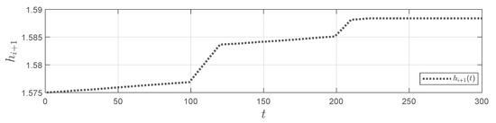
Figure 4.
variation in the strip piling.
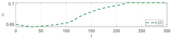
Figure 5.
in the strip piling.
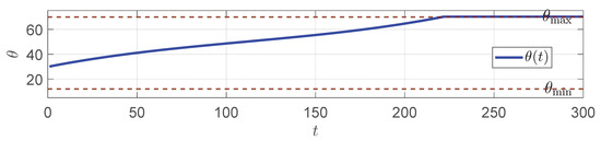
Figure 6.
in the strip piling.
From the figures, it is observed that the looper angle reaches the upper limit of 70°, reflecting a severe strip piling phenomenon.
Another typical abnormal condition is the strip tension scenario, where the system’s initial angle is set to be small, with 20°. Figure 7, Figure 8 and Figure 9 show the response process for various variables under the uncompensated condition.
Figure 7.
variation in the strip tension.
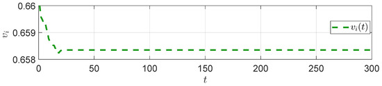
Figure 8.
in the strip tension.
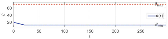
Figure 9.
in the strip tension.
From the figures, we can see that was not promptly increased to match the downstream speed changes, which resulted in the looper length continuing to decrease and approaching the lower limit of 12°. This indicates a significant strip tension risk. Combined with both the strip piling and strip stretching scenarios, this further illustrates the necessity of designing a speed compensation controller.
Thus, we perform simulations of the PSO-MPC-based speed compensation algorithm for the hot rolling process. The simulation sampling period is set to , the prediction horizon is , and the total simulation steps are 300. The target looper angle is set to 25°. The compensation factor k is constrained within the interval , and the front stand speed is limited to the range . The PSO parameters are set as 30 particles, a maximum iteration count of 50, an inertia weight , and learning factors .
Figure 10 shows the trend in the compensation parameter during the simulation process. It can be observed that the compensation factor can adaptively adjusted according to the disturbance. Figure 11 shows the front stand speed curve. With the compensation from , the speed is always kept within the safe range, ensuring the operational safety of the equipment. Figure 12 shows the looper angle response curve, indicating that the looper angle approaches the ideal value through the PSO-MPC control, thus solving the strip piling issue.
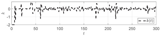
Figure 10.
variation in the strip piling.
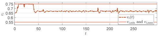
Figure 11.
response in the strip piling.
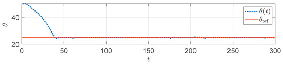
Figure 12.
response in the strip piling.
A simulation is also conducted for another typical abnormal condition: strip tension. In contrast to strip piling, strip tension corresponds to an initial system state that is set to be smaller, with the initial looper angle set to 15°. Meanwhile, a disturbance is applied that continuously decreases the downstream thickness . The other parameters are kept the same as in the strip piling scenario. Figure 13 shows the variation trend in the compensation parameter in the strip tension. Figure 14 displays the adjustment process of the front stand speed after compensation, which remains within the allowable range. Figure 15 shows that the looper angle successfully rises to near the reference value, fully demonstrating that the parameter k can effectively address the strip tension risk.
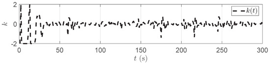
Figure 13.
variation in the strip tension.
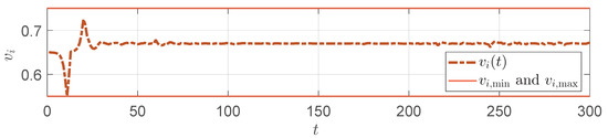
Figure 14.
response in the strip tension.
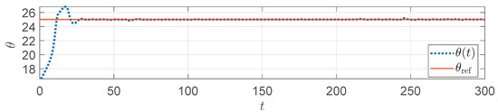
Figure 15.
response in the strip tension.
During the operation of the compensation controller, the PSO algorithm iteratively optimizes the compensation parameter sequence k within the prediction horizon at each time step to minimize the cost function J. At a simulation step , the trend in the cost function during the particle swarm optimization iteration is recorded, as shown in Figure 16. It can be seen that PSO can quickly converge to an optimal solution within a limited number of iterations. This rapid convergence indicates that the algorithm has practical feasibility for real-time industrial applications, as it can obtain effective compensation parameters within the short control cycle of the rolling process. Therefore, PSO ensures that the controller can respond to process fluctuations promptly and maintain looper stability in actual production.
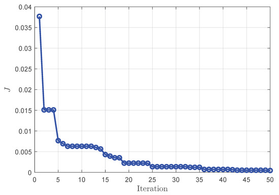
Figure 16.
Cost function convergence curve at simulation step .
6. Concluding Remarks
This paper addresses the issues of strip piling and strip tension caused by improper coordination between stands in the hot rolling process. A dynamic simulation model of the looper system is constructed, and a PSO-MPC-based speed compensation strategy is proposed to achieve dynamic compensation under abnormal scenarios.
- Nonlinear state-space modeling: By introducing a speed compensation parameter, the incremental equations for the front and rear stand speeds, strip thickness, and looper angle are derived. Based on these relationships, a nonlinear state-space model is established, where the speed compensation parameter and roll gap variation serve as inputs, and the looper length and angle serve as outputs.
- PSO–MPC-based compensation strategy: In the control algorithm design, MPC is combined with PSO to formulate a rolling optimization problem. The looper angle is defined as the optimization objective, while the speed compensation factor acts as the control variable. Through iterative optimization, the PSO algorithm obtains the optimal compensation sequence, thereby achieving precise dynamic compensation under abnormal conditions.
However, the present model have the following limitations. First, the looper length–angle relationship is approximated using cubic regression, which may not capture all plant nonlinearities. Second, the current formulation assumes idealized measurements (limited sensor noise and negligible communication/actuation delays). For further testing, we propose the following staged plan: (1) Using recorded historical data, perform parameter identification to more precisely fit and calibrate the mapping between the looper angle and looper length. (2) Extend the existing state-space model to include explicit representations of communication and actuation delays. (3) Profile the PSO–MPC solver on an on-site server, measuring and reporting the average computation time per control cycle, memory footprint, and scalability with respect to the prediction horizon and particle count, in order to assess feasibility under real control cycles and to guide algorithmic optimization.
The method proposed in this paper is based on mechanism modeling and follows the approach of “constructing an optimization problem + solving”. It can effectively address typical abnormal scenarios, such as strip piling and strip tension, and achieve precise tracking of the looper angle in the hot rolling system.
Author Contributions
Conceptualization, S.Z.; methodology, S.Z.; software, J.G.; validation, S.Z. and J.G.; formal analysis, J.G.; investigation, S.Z.; resources, S.Z.; data curation, J.G.; writing—original draft preparation, J.G.; writing—review and editing, J.G.; visualization, J.G.; supervision, S.Z.; project administration, S.Z. All authors have read and agreed to the published version of the manuscript.
Funding
This research received no external funding.
Data Availability Statement
The original contributions presented in this study are included in the article. Further inquiries can be directed to the corresponding author.
Conflicts of Interest
The authors declare no conflicts of interest.
References
- Tan, Y.; Zhou, M.; Guo, X.; Qi, L. A hybrid MIP–CP approach to multistage scheduling problem in continuous casting and hot-rolling processes. IEEE Trans. Autom. Sci. Eng. 2019, 16, 1860–1869. [Google Scholar] [CrossRef]
- Ding, H.; Wang, Y.; Shen, H. A reinforcement learning integral sliding mode control scheme against lumped disturbances in hot strip rolling. Appl. Math. Comput. 2024, 465, 128407. [Google Scholar] [CrossRef]
- Hu, K.; Ye, J.; Song, W. Vulnerability assessments of induction machine-based multistage rolling mill system under sensor integrity attacks. IEEE Trans. Ind. Inform. 2024, 20, 8616–8627. [Google Scholar] [CrossRef]
- Jing, F.; Li, F.; Song, Y.; Li, J.; Feng, Z.; Guo, J. Root cause tracing using equipment process accuracy evaluation for looper in hot rolling. Algorithms 2024, 17, 102. [Google Scholar] [CrossRef]
- Knight, C.W.; Hardy, S.J.; Lees, A.W.; Brown, K.J. Influence of roll speed mismatch on strip curvature during the roughing stages of a hot rolling mill. J. Mater. Process. Technol. 2005, 168, 184–188. [Google Scholar] [CrossRef]
- Dong, Q.; Cao, J.; Li, H.; Zhou, Y.; Yan, T.; Wang, W. Analysis of Spalling in Roughing Mill Backup Rolls of Wide and Thin Strip Hot Rolling Process. Steel Res. Int. 2015, 86, 129–136. [Google Scholar] [CrossRef]
- Park, C.; Hwang, I. New tension control at the head of strip in hot strip finishing mill. J. Mater. Process. Technol. 2008, 206, 69–77. [Google Scholar] [CrossRef]
- Andryushin, I.Y.; Shubin, A.G.; Gostev, A.N.; Radionov, A.A.; Karandaev, A.S.; Gasiyarov, V.R.; Khramshin, V.R. Automatic tension control in the continuous roughing train of a wide-strip hot-rolling mill. Metallurgist 2017, 61, 366–374. [Google Scholar] [CrossRef]
- Gao, H.; Li, X.; Jin, S.; Qin, Y.; Cao, J.; Luan, F.; Zhang, D. Strip deviation analysis and prediction based on time series methods in hot rolling process. J. Manuf. Process. 2024, 131, 1143–1157. [Google Scholar] [CrossRef]
- Hong, W.K.; Kim, P.H.; Moon, Y.H.; Yi, J.J. Hot strip width control method by using looper tension measuring system in finishing mill. J. Mater. Process. Technol. 2001, 111, 74–78. [Google Scholar] [CrossRef]
- Meng, L.; Ding, J.; Li, X.; Cao, G.; Li, Y.; Zhang, D.H. Novel shape control system of hot-rolled strip based on machine learning fused mechanism model. Expert Syst. Appl. 2024, 255, 124789. [Google Scholar] [CrossRef]
- Liu, H.; Li, X.J. Data-driven H_ /H∞ fault detection and control in finite-frequency domain with application to steel rolling process. IEEE Trans. Autom. Sci. Eng. 2025, 22, 252–263. [Google Scholar] [CrossRef]
- Wang, H.; Jing, Y.; Yu, C. Guaranteed cost sliding mode control for looper–tension multivariable uncertain systems. Nonlinear Dyn. 2015, 80, 39–50. [Google Scholar]
- Huang, Y.C.; Peng, C.C. Rolling mill looper-tension control for suppression of strip thickness deviation by adaptive PI controller with uncertain forward/backward slip. Machines 2025, 13, 238. [Google Scholar]
- Yin, F.; Sun, J.; Peng, W.; Wang, H.; Yang, J.; Zhang, D.H. Dynamic matrix predictive control for a hydraulic looper system in hot strip mills. J. Cent. South Univ. 2025, 2, 1369–1378. [Google Scholar] [CrossRef]
- Chen, J.; Yang, W.; Sun, Y. H∞ control of looper-tension control systems based on a discrete-time model. J. Iron Steel Res. Int. 2013, 20, 28–31. [Google Scholar] [CrossRef]
- Choi, I.S.; Rossiter, J.A.; Fleming, P.J. Looper and tension control in hot rolling mills: A survey. J. Process. Control 2006, 17, 509–521. [Google Scholar] [CrossRef]
- Yildiz, S.K.; Forbes, J.F.; Huang, B.; Zhang, Y.; Wang, F.; Vaculik, V.; Dudzic, M. Dynamic modelling and simulation of a hot strip finishing mill. Appl. Math. Model. 2009, 33, 3202–3225. [Google Scholar] [CrossRef]
- Gaber, A.; Elnaggar, M.; Fattah, H.A. Looper and tension control in hot strip finishing mills based on different control approaches. J. Eng. Appl. Sci. 2022, 69, 100. [Google Scholar] [CrossRef]
- Kugi, A.; Haas, W.; Schlacher, K.; Aistleitner, K.; Frank, H.M.; Rigler, G.W. Active compensation of roll eccentricity in rolling mills. IEEE Trans. Ind. Appl. 2002, 36, 625–632. [Google Scholar] [CrossRef]
- Yan, X.; Qi, J.; Wang, X. An active method suppressing rolling mill vibration: Disturbance estimation and compensation algorithm. J. Iron Steel Res. Int. 2019, 26, 697–703. [Google Scholar] [CrossRef]
- Abeyrathna, B.; Rolfe, B.; Hodgson, P.; Matthias, W. A first step towards a simple in-line shape compensation routine for the roll forming of high strength steel. Int. J. Mater. Form. 2016, 9, 423–434. [Google Scholar] [CrossRef]
- Peng, Y.; Hu, Y.; Wang, Y.; Jia, R.; Guo, J. Optimal Consensus Control Strategy for Multi-Agent Systems Under Cyber Attacks via a Stackelberg Game Approach. IEEE Trans. Autom. Sci. Eng. 2025, 22, 18875–18888. [Google Scholar] [CrossRef]
- Guo, J.; Zhang, Q.; Zhao, Y. Identification of FIR Systems with binary-valued observations under replay attacks. Automatica 2025, 172, 112001. [Google Scholar] [CrossRef]
- Jia, R.; Wang, T.; Xue, W.; Guo, J.; Zhao, Y. Multi-Time Scale Consensus Algorithm of Multi-Agent Systems with Binary-valuedData under Tampering Attacks. IEEE Trans. Ind. Inform. 2025. [Google Scholar] [CrossRef]
- Guo, J.; Wang, X.; Xue, W.; Zhao, Y. System identification with binary-valued observations under data tampering attacks. IEEE Trans. Autom. Control 2021, 66, 3825–3832. [Google Scholar] [CrossRef]
- Xu, Q.; Dong, J.; Peng, K.; Yang, X. A novel method of neural network model predictive control integrated process monitoring and applications to hot rolling process. Expert Syst. Appl. 2024, 237, 121682. [Google Scholar] [CrossRef]
- Idzik, C.; Krämer, V.; Hirt, G.; Lohmar, J. Coupling of an analytical rolling model and reinforcement learning to design pass schedules: Towards properties controlled hot rolling. J. Intell. Manuf. 2024, 35, 1469–1490. [Google Scholar] [CrossRef]
- Zhang, W.; Wu, M.; Du, S.; Chen, L. Plate shape recognition based on Gaussian function and particle swarm optimization for roller quenching process. J. Process Control 2022, 119, 115–127. [Google Scholar] [CrossRef]
- Huang, Y.; Lagare, R.B.; Bailey, P.; Sixon, D.; Gonzalez, M.; Nagy, Z.K.; Reklaitis, G.V. Hybrid model development and nonlinear model predictive control implementation for continuous dry granulation process. Comput. Chem. Eng. 2024, 183, 108586. [Google Scholar] [CrossRef]
- Liu, Y.; Peng, P.; Wang, L.; Wu, J.; Lei, M.; Zhang, C.; Lei, R. PSO-NMPC control strategy based path tracking control of mining LHD (scraper). Sci. Rep. 2024, 14, 28516. [Google Scholar] [CrossRef] [PubMed]
Disclaimer/Publisher’s Note: The statements, opinions and data contained in all publications are solely those of the individual author(s) and contributor(s) and not of MDPI and/or the editor(s). MDPI and/or the editor(s) disclaim responsibility for any injury to people or property resulting from any ideas, methods, instructions or products referred to in the content. |
© 2025 by the authors. Licensee MDPI, Basel, Switzerland. This article is an open access article distributed under the terms and conditions of the Creative Commons Attribution (CC BY) license (https://creativecommons.org/licenses/by/4.0/).