Article

Effect of Overlap Rate on Microstructure and Corrosion Behavior of Laser-Clad Ni60-WC Composite Coatings on E690 Steel

1
School of Mechanical Engineering, Nantong University, Nantong 226019, China
2
COSCO Shipping (Qidong) Offshore Co., Ltd., Nantong 226200, China
3
School of Information Science and Technology, Nantong University, Nantong 226019, China
*
Authors to whom correspondence should be addressed.
Metals 2025, 15(10), 1153; https://doi.org/10.3390/met15101153
Submission received: 17 September 2025 / Revised: 13 October 2025 / Accepted: 15 October 2025 / Published: 17 October 2025
(This article belongs to the Special Issue Fabricating Advanced Metallic Materials)

Abstract

To investigate the influence of laser cladding overlap rate on the microstructure and corrosion resistance of cladded layers, Ni60-WC composite coatings with different overlap rates (30%, 50%, and 70%) were prepared on E690 offshore steel in this study. The relationship between the corrosion resistance and microstructure of the cladded layers fabricated at different overlap rates was analyzed using an electrochemical workstation, scanning electron microscope, X-ray diffractometer, and energy dispersive spectrometer. The results demonstrate that the overlap rate exerts a significant impact on the corrosion resistance of the cladded layers, and the corrosion resistance of the cladded layers gradually improves with the increase in overlap rate. The cladded layer prepared with a 70% overlap rate exhibits excellent corrosion resistance, featuring the highest open-circuit potential (−0.31 V vs. SCE), the lowest corrosion current density (3.35 μA/cm2), the largest capacitive arc radius in the electrochemical impedance spectroscopy (EIS), and a relatively flat surface after corrosion tests. Microstructural characterization results indicate that the increase in overlap rate promotes grain refinement and the formation of reinforcing phases (e.g., M23C6). The coating with a 70% overlap rate possesses the densest microstructure and abundant flocculent carbides, which act as an effective barrier against the penetration of corrosive media, thereby endowing it with optimal performance.

1. Introduction

The extensive application of E690 steel on pile leg components of offshore platforms is often plagued by severe corrosion in harsh marine environments, which not only affects structural integrity, but also poses substantial safety risks to offshore platforms [1]. Considering the high manufacturing cost of pile legs, developing effective repair strategies for corroded regions holds both economic and practical significance. Since corrosion usually occurs first in the splash zone of the pile leg, the preparation of protective coatings on the E690 steel can effectively solve this problem [2]. Laser cladding, an advanced surface engineering technique, has emerged as a promising solution for this challenge [3]. This technology feeds corrosion-resistant powder on the damaged part and uses a high-energy density laser beam to rapidly heat and melt the powder along with the substrate surface, forming a metallurgically bonded composite coating. This process not only repairs the corroded part but also significantly improves the corrosion resistance of components [4,5,6]. As such, it provides an effective solution to the corrosion problems of offshore platform pile legs. Although laser cladding has great application potential in the field of surface repair, research on laser cladding applications for E690 steel remains limited, particularly concerning the corrosion resistance of the composite coatings [7,8,9].
Tungsten carbide (WC) has good wettability with nickel (Ni); it is widely used for surface modification of metallic materials due to its high hardness and good corrosion resistance [10,11]. Cao et al. [12] fabricated Ni-WC coating by laser cladding on the AISI 4145H steel and studied the effect of different Y2O3 additions on the corrosion resistance of the coating. The results showed that the coating with 0.5 wt% Y2O3 addition showed the best corrosion resistance among all specimens. Wang et al. [13] developed a Ni-WC/Al-Ni functionally graded coating on AZ91D Mg alloy, achieving superior corrosion protection through gradient microstructure design. Ge et al. [14] identified 2500 W as the optimal laser power for fabricating Ni-60%WC coatings on H13 steel, yielding the highest corrosion resistance. Zeng et al. [15] reported that a scanning speed of 120 mm/min maximized microhardness and corrosion resistance in Ni-WC coatings on AlSi5Cu1Mg alloy. Nevertheless, although parameters such as laser power and scanning speed have been extensively studied, the role of overlap rate (OR) in multi-pass cladding—a critical factor controlling thermal history, dilution, and inter-track bonding—has received relatively less attention, particularly in the context of laser cladding of Ni60-WC on E690 steel. The OR defined by Equation (1) is a critical parameter in laser cladding that dictates the morphology and quality of the clad layer. It is calculated from the single-track clad width (W) and the center-to-center distance (D) between adjacent tracks.
O R = 1 D W × 100 %
The OR value governs the interaction between successive tracks. An OR of 0% (D = W) results in grooves and poor density due to non-overlapping tracks. Conversely, as OR approaches 100% (D→0), excessive energy and material accumulation cause defects like stress concentration and high dilution. Therefore, selecting an appropriate OR within the 0–100% range is essential for achieving a dense, continuous, and defect-free clad layer with controlled residual stress and surface flatness [16].
To address this issue, the present study employed Ni60-WC powder to repair defective E690 high-strength steel samples under optimized process parameters, with the overlap rate as the variable. The effects of OR (30%, 50%, 70%) on the microstructural evolution and corrosion mechanism of Ni60-WC coatings on E690 steel were carefully investigated. The research findings provide mechanistic insights and practical guidance for optimizing laser cladding processes in marine applications.

2. Materials and Methods

E690 steel (Baowu Steel, Shanghai, China), a high-strength low-alloy (HSLA) steel used in marine equipment, was employed as the substrate material. The cladding feedstock consisted of Ni60-WC (Chengfeng, Foshan, China) composite powder with a bimodal particle size distribution (30–150 μm), containing 65 wt% tungsten carbide reinforcement (purity: 99.9%). Detailed chemical compositions of both the E690 substrate and Ni60 binder phase are summarized in Table 1. Prior to cladding, rectangular coupons (50 mm × 50 mm × 10 mm) were sectioned via wire-cutting from the base metal. The cladding surfaces were progressively ground using SiC abrasive papers (Jicheng, Hubei, China) from #240 to #2000 grit to achieve a surface roughness (Ra) < 0.8 μm, followed by ultrasonic cleaning in 95% ethanol for 15 min (frequency: 40 kHz, temperature: 25 °C) to remove surface contaminants. To minimize residual stress, all specimens underwent preheating at 150 °C for 2 h in a vacuum furnace (SIMUWU, Shanghai, China) before laser processing.
The Ni60-WC composite powder was deposited on the E690 steel substrate using the coaxial powder-feeding laser cladding system (Raycham, Nanjing, China) (as shown in Figure 1). Prior to cladding, the substrate surface was sanded with SiC abrasive papers to remove the oxide layer, followed by ultrasonic cleaning in 95% ethanol (40 kHz, 25 °C) for 15 min to ensure surface cleanliness. During the cladding process, the Ni60-WC powder was conveyed to the molten pool by a powder feeder, with high-purity argon (99.99%) serving as the powder carrier gas—this same argon also functioned as the shielding gas for the entire process. Simultaneously, the substrate surface was irradiated by a high-power laser beam (TEM00 mode) to melt the delivered powder and a thin layer of the substrate material, thereby creating a metallurgically bonded cladding layer. The optimized process parameters detailed in Table 2 were applied to fabricate single-layer multi-pass coatings with controlled overlap rates of 30%, 50%, and 70%. Post-cladding, the cladded specimens were cut into sizes of 15 mm × 15 mm × 10 mm using electric discharge cutting technology. Cross-sectional surfaces were progressively ground with SiC abrasive papers (#240 to #2000 grit) and mirror-polished using diamond suspension on a vibratory polishing system. To eliminate residual polishing compounds, all specimens underwent ultrasonic cleaning in 95% ethanol (40 kHz, 25 °C) for 15 min, followed by nitrogen drying prior to characterization.
Electrochemical corrosion tests were performed using an electrochemical workstation (CHI660C, Chenhua, Shanghai, China) with a conventional three-electrode system, As shown in Figure 2 The tests were conducted in a 3.5 wt% NaCl aqueous solution, which simulates the concentration of seawater. All experiments were carried out at room temperature (approximately 25 °C) and under atmospheric pressure (1 atm). The working electrode was the specimen with an exposed area of 1 cm2. A platinum sheet served as the counter electrode, and a saturated calomel electrode (SCE) was used as the reference electrode.
The surface morphology and microstructural characteristics of the composite coatings, as well as the post-corrosion surface topography, were meticulously examined using a field emission high-resolution scanning electron microscope (FE-SEM, JSM-7000F, JEOL, Tokyo, Japan). For phase composition analysis, X-ray diffraction (XRD) measurements were conducted using a Rigaku Ultima IV diffractometer (Rigaku Corporation, Tokyo, Japan). The energy dispersive spectrometer was used to measure the elemental composition of the coatings.

3. Results and Discussion

3.1. Analysis of Electrochemical Corrosion Performance of Composite Coating

Figure 3 presents the time-dependent evolution of open circuit potential (OCP) for specimens in 3.5 wt% NaCl solution. The OCP reflects the tendency of electrochemical corrosion, with a lower value indicating that the specimen is more susceptible to oxidation and corrosion [17]. The OCP of the E690 steel substrate exhibited a gradual and slow decline, with a final value of −0.64 V vs. SCE, which indicates that it is difficult to form an effective protective film on the substrate surface during the corrosion test. In contrast, laser-clad specimens demonstrated markedly improved electrochemical stability. The composite coating with 30% overlap rate achieved an OCP of −0.34 V vs. SCE, while specimens with 50% and 70% overlap rates both attained −0.31 V vs. SCE. The OCP of the coatings shifted positively by approximately 0.33 V, representing a 51.6% improvement relative to the substrate’s potential. Overall, the differences in OCP among the specimens with different overlap rates were minimal. The OCP of the substrate was significantly lower. The OCPs of specimens with overlap rates of 50% and 70% were closer to positive values, indicating the formation of a denser passivation film on the coating surface [18], which significantly reduced the corrosion tendency.
Figure 4 displays the potential dynamic polarization curves of specimens in corrosive media. All composite coatings demonstrated comparable polarization behavior with distinct passivation regions, though notable differences emerged in their electrochemical responses. The 50% and 70% overlap rate coatings exhibited more pronounced passivation regions, indicating that the coatings are more likely to form a passivation film during the corrosion process, thereby significantly inhibiting corrosion. Following the passivation region, a rapid rise in current density occurred at approximately −0.31 V vs. SCE, corresponding to breakdown events in the protective oxide layer under increasing anodic polarization, as documented in prior studies [19,20]. This breakdown leads to a reduction in the corrosion resistance of the specimens. Subsequently, a smaller passivation zone reappears, indicating that the passivation film of the composite coating has a strong ‘self-healing’ ability after corrosion rupture. Electrochemical parameters extracted through Tafel extrapolation (Table 3) reveal significant improvements in the corrosion resistance of the specimens. The 70% overlap coating showed the lowest icorr (3.35 μA/cm2), representing a 61.2% reduction compared to the substrate (8.63 μA/cm2). After laser cladding, the Ecorr of the cladded specimens shifted positively, and the icorr decreased significantly compared to the substrate, indicating a reduction in corrosion rate and an improvement in corrosion resistance. Among the specimens, the icorr followed the order: 70% < 50% < 30% < substrate. These results demonstrate that the composite coating with a 70% overlap rate has better corrosion resistance.
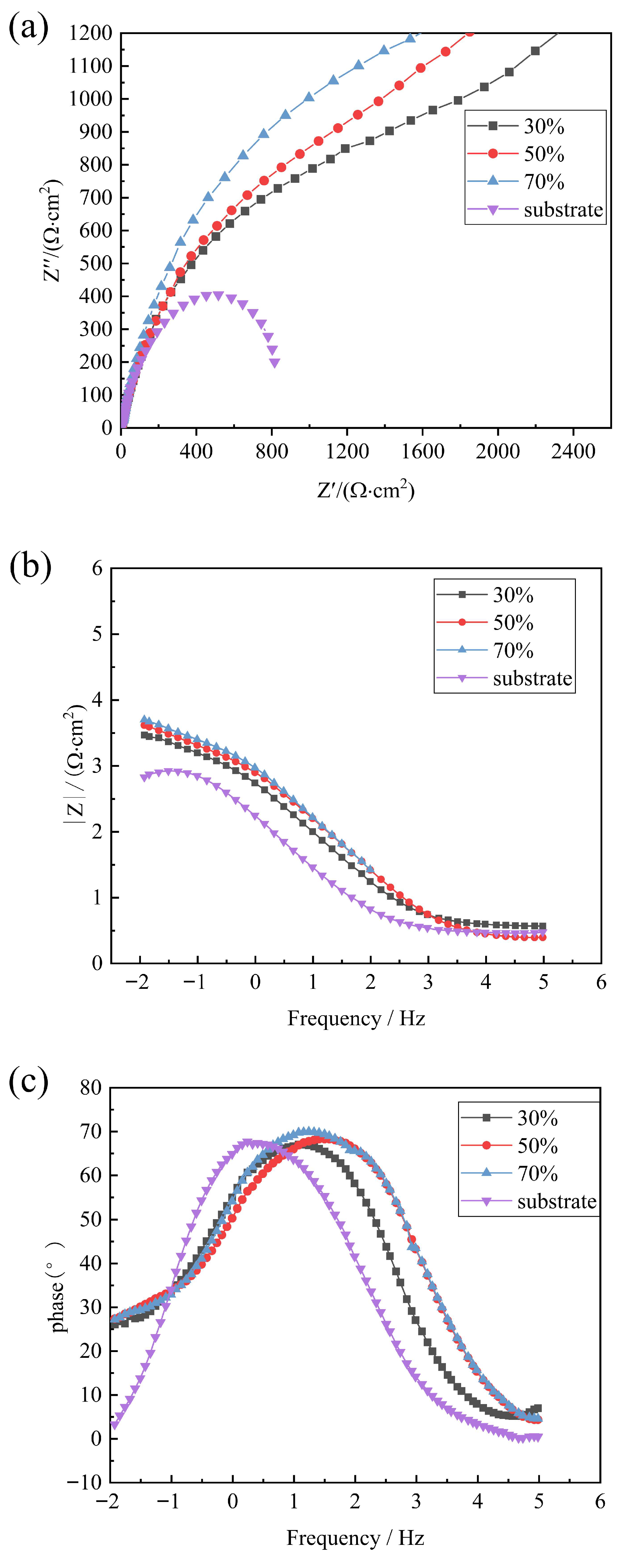
Figure 5a presents the Nyquist plots of the composite coatings and substrate, where the real impedance (Z′) and imaginary impedance (Z″) represent resistive and capacitive/reactance components, respectively. The Nyquist plot is used to evaluate the corrosion resistance of materials in corrosive environments. The capacitive arc radius in the low-frequency domain (10−1–101 Hz) directly correlates with corrosion resistance—larger radii indicate superior barrier properties against charge transfer processes. All specimens exhibited single capacitive semicircles, confirming a unified charge transfer mechanism at the electrode-electrolyte interface. During electrochemical reactions, metal oxidation (electron loss) at the working electrode couples with cathodic reductions (e.g., H+/OH- reactions) at the counter electrode, while ion adsorption forms a protective double-layer capacitance. Notably, the laser-clad coatings demonstrated capacitive arc radii 3–5 times greater than the substrate, with the hierarchy 70% > 50% > 30% > substrate. This systematic enhancement aligns with polarization curve analyses, confirming optimal corrosion resistance at 70% overlap rate.
Figure 5b,c present the Bode plots of the electrochemical corrosion data, which consist of two curves: Figure 5b shows the |Z|-frequency curve, where the Log|Z| in the low-frequency region corresponds to Rct (charge transfer resistance), and the Log|Z| in the high-frequency region corresponds to Rs (solution resistance). Figure 5c displays the phase angle-frequency curve. From Figure 5b,c, it is evident that the impedance values increase significantly after laser cladding, and the phase angle plateau in the low-frequency region of the composite coatings becomes broader, indicating enhanced corrosion resistance. Each specimen exhibits only one peak in the phase angle curve, suggesting the presence of a single time constant. The width of the peak reflects the corrosion resistance of the corresponding composite coating. In the low-frequency range (10−1~101 Hz), the impedance modulus value |Z| of the composite coating is higher than that of the substrate, and the phase angle of the composite coating is slightly larger than that of the substrate.
By fitting the equivalent circuit model to the electrochemical impedance spectroscopy (EIS) data obtained from the tests, the corrosion resistance of the coatings can be evaluated. Since the Nyquist plot of the substrate specimen only contains one capacitive arc, its equivalent circuit is shown in Figure 5d, where Rs represents the resistance of the NaCl solution, Qc denotes the constant phase element (CPE), and Rct represents the charge transfer resistance. The impedance spectrum of the cladding specimen includes diffusion impedance, and its equivalent circuit is illustrated in Figure 5e, where Rc represents the resistance of the composite coating.
In summary, the corrosion resistance of the coatings on different samples follows the order: 70% OR > 50% OR > 30% OR > substrate. The 70% OR coating exhibits excellent corrosion resistance, which can be attributed to its enhanced microstructural uniformity and more compact passive film-forming ability. The positive shift in corrosion potential (Ecorr) and the decrease in corrosion current density (icorr) indicate a lower thermodynamic tendency toward corrosion and a slower corrosion kinetic rate, respectively [21]. For the sample with 70% OR, the larger radius of the capacitive arc in the Nyquist plot suggests a higher charge transfer resistance (Rct), indicating a more effective barrier against electrolyte penetration [22]. This is consistent with the results from the Bode plots, where the highest magnitude of impedance (|Z|) at low frequencies and the broadest phase angle peak are observed, further confirming the formation of a more stable protective interface.

3.2. Microstructure and Performance Analysis of Composite Coatings

The cross-sectional morphologies of the composite coatings fabricated at overlap rates of 30%, 50%, and 70% were analyzed via scanning electron microscopy (SEM) to elucidate the microstructural evolution and its correlation with corrosion resistance, as illustrated in Figure 6. The SEM micrographs confirm that all coatings exhibit defect-free microstructures, characterized by the absence of pores and cracks, alongside a well-organized arrangement of morphological features.
The temperature gradient (G) and the solidification rate (R) synergistically determine the microstructure morphology during laser cladding [23]. During the initial cladding stage, rapid heat transfer from the molten pool to the substrate elevates the substrate temperature, thereby reducing (G) at the pool bottom while increasing (R), which in turn decreases the ratio of the temperature gradient (G) to the solidification rate (R). Subsequently, under conditions of limited component supercooling, a large number of columnar crystals and cellular crystals and a small number of dendrites are formed in the bottom area of the coating in the opposite direction of the heat flow, and many white eutectic structures are generated between these crystals. The structure morphology is shown in Figure 6a–c.
The mid-region of the coating (Figure 6d–f) is dominated by dense dendrites. The grains in the middle of the coating with a 30% overlap rate exhibit relatively coarse dendrites. As the overlap rate increases to 50%, the grains are further refined. At an overlap rate of 70%, the structure becomes even finer and denser, consisting of numerous fine strip crystals. These strip crystals lack a fixed orientation, and the overall microstructure presents a fine and dense dendritic structure arrangement. Zhang et al. [24] attributed this refinement to secondary crystallization in overlapped regions, where remelting of coarse columnar crystals generates slender grains. At an overlap rate of 70%, the remelted portion of the composite coating increases, and the heat absorbed by the composite coating intensifies, causing the grains at the top and middle of the composite coatings to continue growing after crystallization.
Near the coating surface (Figure 6g–i), the interplay between latent heat absorption from the substrate and convective cooling by protective gas minimizes the (G/R) ratio, enabling multidirectional heat dissipation. According to the studies of Zhang and Xue et al. [25,26], some WC particles in the molten pool are dissolved by high-energy laser heating. The fragmented WC particles, along with the dissolved W and C elements, are separated and distributed within the metal solution, where they interact with Ni, Cu, and W in the Ni-based alloy matrix, ultimately solidifying to form cellular crystals, flocculent carbides, and strip crystals with random orientations. The top of the composite coating with a 30% overlap rate exhibits abundant strip crystals but sparse flocculent carbides. As the overlap rate increases, the number of strip crystals decreases while the flocculent carbides increase, correlating with enhanced corrosion resistance due to the barrier effect of carbides against corrosive media penetration.
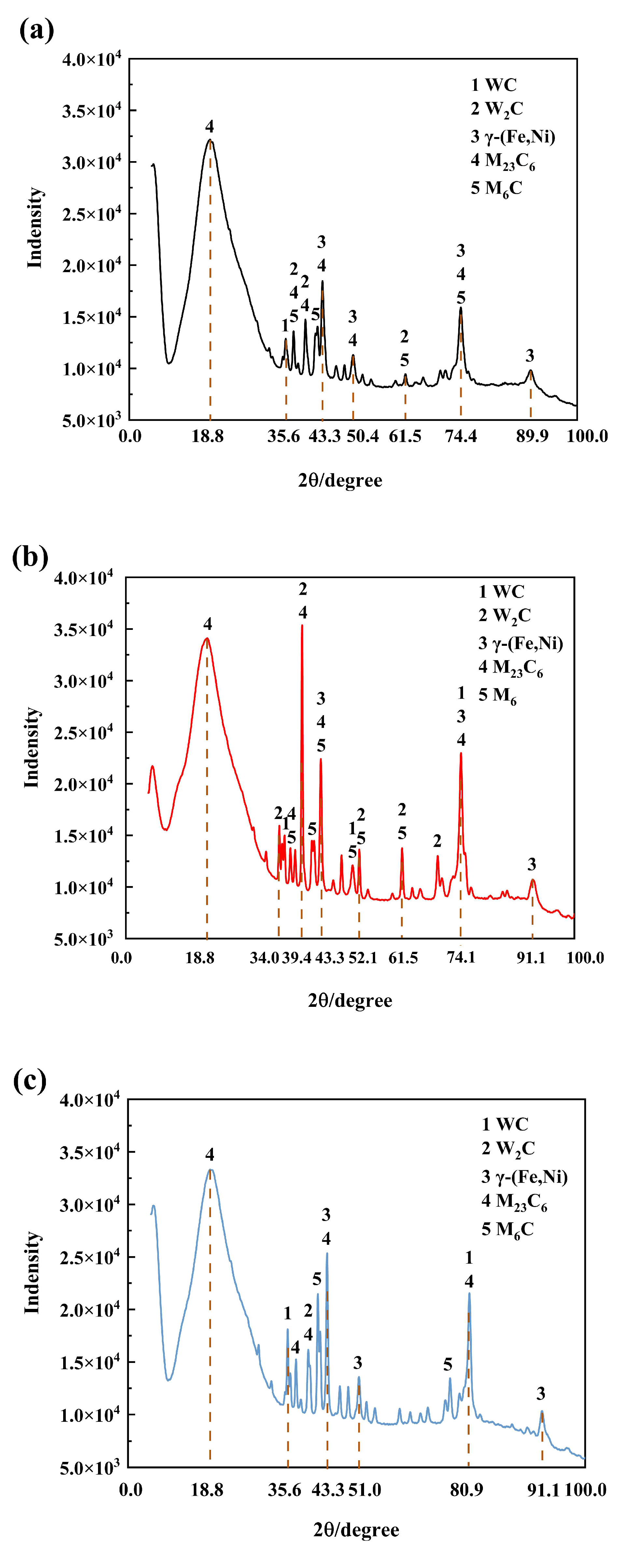
The XRD patterns of composite coatings fabricated at different overlap rates are presented in Figure 7. All coatings exhibit similar chemical compositions across the tested overlap rates. The composite coating primarily consists of γ-(Fe, Ni), WC, W2C, M23C6 and M6C (where M represents Fe, Ni, Cu, W, etc.). The matrix phase of the composite coating is γ-(Fe, Ni), while the reinforcement phase is WC, W2C, M23C6 and M6C. A stronger diffraction peak intensity of a given phase indicates a more preferred growth orientation, suggesting that variations in the overlap rate can influence the preferred growth orientation of the phases in the coating. Notably, the coating produced at 30% overlap rate shows relatively weak diffraction intensities for all phases. Optimal crystallization occurs at 50% overlap rate, evidenced by enhanced peak intensities for both γ-(Fe, Ni) and M23C6 phases. When increasing to 70% overlap rate, we observe a slight reduction in peak heights for these phases coupled with marginal full width at half maximum (FWHM) broadening, suggesting grain refinement within the coating microstructure. This phenomenon aligns with thermal history variations induced by overlap rate adjustments, where increased energy input at higher overlap rates promotes nucleation over crystal growth. The (Fe, Ni) solid solution serves as a binder and support for these reinforcement phases [27].
The Ni60-WC coating is a typical multi-phase composite, as confirmed by XRD (Figure 7). Consequently, a high density of grain boundaries (within the γ-(Fe, Ni) matrix) and phase boundaries (between the matrix, carbides like M23C6, and undissolved WC particles) are inherently present, as clearly observed in the SEM micrographs (Figure 6). These interfaces play a critical role in determining the coating’s properties. While they can potentially serve as initiation sites for corrosion if compositional heterogeneity exists, the refined and homogeneous microstructure obtained at 70% OR, with its uniformly distributed fine boundaries, promotes the formation of a more continuous and protective passive film. This effect outweighs the potential negative aspects, contributing to the superior corrosion resistance observed [28].
The X-ray diffraction (XRD) analysis revealed that the composite coating with 70% overlap rate exhibited significant grain refinement characteristics. To further investigate the elemental distribution features of the Ni-WC composite coating, energy dispersive spectroscopy (EDS) point scanning analysis was conducted on the surface region of the 70% overlap rate coating. As shown in Figure 8, three typical microstructures were identified in the test area: white spherical particles (Zone A), white flocculent eutectic carbides (Zone B), and cellular crystals (Zone C). The quantitative analysis data in Table 4 demonstrated that the coating primarily consisted of Ni and Fe-W elements, with trace amounts of Cu and C.
Combined with the research by Ma et al. [29] on elemental migration at laser-clad interfaces, Fe elements from the substrate entered the molten pool through thermal diffusion during the cladding process, forming multi-component solid solutions and intermetallic compounds with Ni and W. Microstructural analysis indicated that the white spherical particles in Zone A represented incompletely decomposed WC hard phases, while the surrounding white blocky structures (containing 46.1 wt% W) originated from W element segregation during solidification. Thermodynamic analysis demonstrated that during the initial cooling stage of the molten pool (T > 1600 °C), W-enriched zones formed in the liquid phase due to concentration fluctuations, preferentially nucleating and evolving into M23C6 or M6C-type carbides through the Ostwald ripening mechanism.
Table 4 data further revealed: Zone A exhibited significant W-C-O enrichment characteristics (W: 46.1 wt%, C: 31.2 wt%, O: 4.6 wt%). Combined with XRD phase identification results, this suggests the presence of thermally decomposed and recrystallized W2C phases in this region. The W content in Zone B eutectic carbides decreased to 33.8 wt%, while Fe and Ni contents increased to 21.8 wt% and 23.8 wt%, respectively, consistent with the chemical stoichiometry of M23C6-type carbides. In Zone C cellular crystals, the Fe/Ni ratio approached 1:1 (Fe: 17.2 wt%, Ni: 17.4 wt%) with 45.7 wt% W content, indicating this region corresponds to face-centered cubic γ-(Fe,Ni) solid solutions.

3.3. Morphology Analysis After Electrochemical Corrosion

The post-corrosion surface morphologies of specimens under different processing parameters are systematically presented in Figure 9. As illustrated in Figure 9a, the E690 steel substrate exhibits substantial corrosion damage characterized by abundant rough and loosely adherent corrosion products, accompanied by extensive surface spalling indicative of severe material degradation.
Figure 9b shows the post-corrosion morphologies of specimen with a 30% overlap rate. The surface of the composite coating appears relatively smooth; however, numerous spalling pits and a small number of corrosion holes are evident. The enhanced corrosion performance can be primarily attributed to the γ-(Fe, Ni) matrix phase with face-centered cubic (FCC) structure, which demonstrates superior chemical stability compared to conventional steel substrates [30]. However, at 30% overlap rate, insufficient laser energy input results in incomplete WC decomposition, leading to inadequate formation of reinforcement phases (M23C6 and W2C) as confirmed by XRD analysis in Figure 7a. This energy deficiency also restricts secondary crystallization, resulting in coarse microstructural features observable in Figure 6d–g, ultimately compromising the coating’s barrier effectiveness against corrosive media.
Figure 9c shows the post-corrosion morphologies of specimen with a 50% overlap rate. The corroded surface remains relatively smooth, with only a few spalling pits observed. Significant microstructural evolution occurs at 50% overlap rate (Figure 6e,h), where optimized laser energy distribution promotes the formation of strip-like and flocculent carbide reinforcements. EDS mapping reveals these features correspond to M23C6, whose homogeneous distribution synergistically enhances electrochemical stability. This microstructural refinement correlates with superior corrosion resistance.
Figure 9d shows the post-corrosion morphologies of specimen with a 70% overlap rate. The surface of the composite coating is notably smooth, with only a very small number of spalling pits, demonstrating a significant improvement in corrosion resistance. The enhanced corrosion resistance can be attributed to the synergistic action of WC particles and their decomposition products. The inherently stable and hard WC phases serve as effective physical barriers, blocking the penetration of corrosive chloride ions and thereby increasing the coating’s compactness. Under the optimized thermal conditions in the molten pool at the 70% overlap rate, more complete decomposition of WC occurs, leading to considerable dissolution of W and C into the Ni–Cu–W matrix. This promotes the formation of multiple reinforcing phases such as W2C, M23C6, and M6C. In particular, EDS analysis confirms that the characteristic flocculent structures in Figure 6i correspond to M23C6 carbides, which help catalyze the development of a dense passivation film [31]. Furthermore, the dissolved W and C aid in forming a more stable and compact passive layer on the γ-(Fe, Ni) matrix, substantially reducing the corrosion current density and improving overall passivation performance. At the same time, the steeper temperature gradient (G) induced by the 70% overlap rate promotes secondary crystallization, resulting in significant grain refinement, as shown in Figure 6f. XRD analysis in Figure 7 supports this structural refinement, where peak broadening indicates a clear reduction in grain size. Such a refined microstructure enhances the coating’s ability to block aggressive anions [32].

4. Conclusions

(1)
The matrix phase of the composite coatings is γ-(Fe, Ni), with reinforcing phases including WC, W2C, and flocculent carbides formed. The overlap rate exerts a significant influence on the microstructure of the cladded layers. The cladded layer fabricated with a 30% overlap rate contains coarse dendrites and strip crystals, accompanied by a small quantity of flocculent carbides. The cladded layer prepared at a 50% overlap rate exhibits grain refinement, consisting of fine dendrites, strip crystals, and flocculent carbides. The microstructure of the cladded layer with a 70% overlap rate is further refined, containing numerous fine strip crystals and a large amount of flocculent carbides.
(2)
Laser cladding treatment significantly improves the corrosion resistance of E690 steel surfaces. Electrochemical characterization indicates that the coating with a 70% overlap rate demonstrates excellent corrosion resistance, primarily reflected in three key parameters: ① a notable positive shift in open circuit potential; ② a significant reduction in corrosion current density; and ③ the largest capacitive arc radius in electrochemical impedance spectroscopy analysis.
(3)
The enhanced corrosion resistance is mainly attributed to the acquisition of a denser and more uniform microstructure at a 70% overlap rate, which effectively hinders the penetration of corrosive Cl ions and facilitates the formation of a stable passive film.
Due to the limitations of existing technical means, this study cannot accurately determine the phase composition of individual crystals, and only infers the phase composition of each crystal based on the results of EDS point scanning elemental composition analysis. Future research will continue to focus on the elemental bonding mechanisms and clarify the phase composition of each crystal. It is important to note that this study was conducted under standard laboratory conditions (25 °C, 1 atm). In practical marine applications, especially in deep-sea environments, factors such as increased hydrostatic pressure and lower temperatures can significantly alter corrosion behavior. Elevated pressure can enhance the susceptibility to localized corrosion, while temperature changes directly influence the kinetics of electrochemical reactions and the stability of the passive film. Therefore, future work should focus on evaluating the performance of these coatings under simulated service conditions that more closely mimic the target environment.

Author Contributions

Y.C.: Conceptualization, Methodology, Software, Funding acquisition, Resources; G.G.: Writing—Reviewing and Editing, Visualization, Investigation; R.Z.: Data curation, Formal analysis, Writing—Original draft; M.Q.: Supervision, Project administration; J.Q.: Software, Validation. All authors have read and agreed to the published version of the manuscript.

Funding

This research was funded by Key Project of Basic Science Research (Natural Science) in Colleges and Universities in Jiangsu Province, grant number 25KJA416002; Research on the Precision Control Technology System for the Entire Process of Offshore Module Design and Manufacturing, grant number 24ZH362, and Foundation of National Key Laboratory for Remanufacturing, grant number 61420052022KJW01.

Data Availability Statement

The data presented in this study are available on request from the corresponding author. The data are not publicly available due to to the sensitive nature of the questions asked in this study, survey respondents were assured that the raw data would be kept confidential.

Acknowledgments

We sincerely thank Nantong University for the experimental facilities.

Conflicts of Interest

Author Ming Qiu was employed by the company COSCO Shipping (Qidong) Offshore Co., Ltd. The remaining authors declare that the research was conducted in the absence of any commercial or financial relationships that could be construed as a potential conflict of interest.

Abbreviations

The following abbreviations are used in this manuscript:
ORoverlap rate
WCTungsten carbide
OCPopen circuit potential
EISelectrochemical impedance spectroscopy
HSLAhigh-strength low-alloy
CPEconstant phase element
SEMscanning electron microscopy
Gtemperature gradient
Rsolidification rate
FWHMfull width at half maximum
XRDX-ray diffraction
EDSenergy dispersive spectroscopy
FCCface-centered cubic

References

  1. Hu, J.; Lin, G.; Deng, P.; Li, Z.; Tian, Y. Galvanic Corrosion of E690 Offshore Platform Steel in a Simulated Marine Thermocline. Metals 2024, 14, 287. [Google Scholar] [CrossRef]
  2. Lesyk, D.A.; Mordyuk, B.N.; Martinez, S.; Iefimov, M.O.; Dzhemelinskyi, V.V.; Lamikiz, A. Influence of Combined Laser Heat Treatment and Ultrasonic Impact Treatment on Microstructure and Corrosion Behavior of AISI 1045 Steel. Surf. Coat. Technol. 2020, 401, 126275. [Google Scholar] [CrossRef]
  3. Shan, B.; Chen, J.; Chen, S.; Ma, M.; Ni, L.; Shang, F.; Zhou, L. Laser Cladding of Fe-Based Corrosion and Wear-Resistant Alloy: Genetic Design, Microstructure, and Properties. Surf. Coat. Technol. 2022, 433, 128117. [Google Scholar] [CrossRef]
  4. Luo, X.; Zhang, K.; Cao, J.; Meng, G.; Yu, F.; Zhou, Y.; Zhou, H.; La, P.; Xie, H. Effect of Line Energy Density of the Laser Beam on the Microstructure and Wear Resistance Properties of the Obtained Fe3Al Laser Cladding Coatings. Optik 2022, 261, 169256. [Google Scholar] [CrossRef]
  5. Guo, Y.; Song, S.N.; Huang, Y.B.; Wang, G.L.; Li, Y.B.; Li, Z.Q. Effect of Phase Constituents on Tribological and Corrosion Properties of Fe-Based Laser Clad Carbon Steel. Lasers Eng. 2023, 54, 313–327. [Google Scholar]
  6. Li, S.; Yi, L.; Jia, X.; Xiang, D.; Liu, T.; Ji, B. A Dense and Compact Laser Cladding Layer with Solid Metallurgical Bonding Significantly Improved Corrosion Resistance of Mg Alloy for Engineering Applications. Mater. Corros. 2020, 71, 1442–1452. [Google Scholar] [CrossRef]
  7. Yan, Q.; Yin, Q.; Cui, J.; Wang, X.; Qiao, Y.; Zhou, H. Effect of Temperature on Corrosion Behavior of E690 Steel in 3.5 wt.% NaCl Solution. Mater. Res. Express 2021, 8, 016528. [Google Scholar] [CrossRef]
  8. Wang, J.; Cui, X.; Jin, G.; Zhao, Y.; Wen, X.; Zhang, Y. Effect of In-Situ Ni Interlayer on the Microstructure and Corrosion Resistance of Underwater Wet 316L Stainless Steel Laser Cladding Layer. Surf. Coat. Technol. 2023, 458, 129341. [Google Scholar] [CrossRef]
  9. Jia, D.; Shi, W.; Zhang, H.; Wu, T.; Diao, Y.; Li, K.; Lu, C. Effects of Y2O3 Content on Wear Resistance and Corrosion Resistance of 316L/TiC Coating Fabricated by Laser Cladding. Coatings 2023, 13, 1348. [Google Scholar] [CrossRef]
  10. Liu, Y.; Sun, W.; Tian, S.; Jia, Y.; Xiao, Y. Microstructures and High-Temperature Friction and Wear Behavior of High-Velocity Oxygen-Fuel-Sprayed WC-12%Co-6%Cr Coatings before and after Sealing. J. Mater. Eng. Perform. 2022, 31, 448–460. [Google Scholar] [CrossRef]
  11. Liu, Y.; Xu, T.; Li, G. Research on Wear and Corrosion Resistance of Ni60-WC Coating Fabricated by Laser on the Preheated Copper Alloy. Coatings 2022, 12, 1537. [Google Scholar] [CrossRef]
  12. Cao, Q.; Fan, L.; Chen, H.; Hou, Y.; Dong, L.; Ni, Z. Wear and Corrosion Mechanisms of Ni-WC Coatings Modified with Different Y2O3 by Laser Cladding on AISI 4145H Steel. Sci. Eng. Compos. Mater. 2022, 29, 364–377. [Google Scholar] [CrossRef]
  13. Wang, G.; Wang, S.; Yin, Z.; Yang, X.; Wen, D.; Sun, Y. Synthesis of Ni-WC/Al-Ni Functionally Graded Coating with Advanced Corrosion and Wear Resistance on AZ91D Mg Alloy by Laser Cladding. Mater. Lett. 2023, 333, 133645. [Google Scholar] [CrossRef]
  14. Ge, Y.; Zheng, C.-Y.; Dai, L.-J.; Liu, C.; Kong, D.-J. Effect of Laser Power on the Electrochemical Performance of a Ni-60%WC Alloy Laser Clad Coating on H13 Steel. Laser Eng. 2023, 56, 177–190. [Google Scholar]
  15. Zeng, M.; Yan, H.; Yu, B.; Hu, Z. Microstructure, Microhardness and Corrosion Resistance of Laser Cladding Ni-WC Coating on AlSi5Cu1Mg Alloy. Trans. Nonferrous Met. Soc. China 2021, 31, 2716–2728. [Google Scholar] [CrossRef]
  16. Nie, B.; Xue, Y.; Luan, B. Effect of Overlap Rate on the Microstructure and Corrosion Behavior of Pure Copper Laser Cladding. J. Mater. Sci. 2024, 59, 6564–6582. [Google Scholar] [CrossRef]
  17. Katiyar, P.K.; Randhawa, N.S. Corrosion Behavior of WC-Co Tool Bits in Simulated (Concrete, Soil, and Mine) Solutions with and without Chloride Additions. Int. J. Refract. Met. Hard Mat. 2019, 85, 105062. [Google Scholar] [CrossRef]
  18. Hu, Y.; Wang, Z.; Pang, M. Effect of WC Content on Laser Cladding Ni-Based Coating on the Surface of Stainless Steel. Mater. Today Commun. 2022, 31, 103357. [Google Scholar] [CrossRef]
  19. Human, A.M.; Exner, H.E. Relationship between Electrochemical Behaviour and In-Service Corrosion of WC Based Cemented Carbides. Int. J. Refract. Met. Hard Mater. 1997, 15, 65–71. [Google Scholar] [CrossRef]
  20. Human, A.M.; Exner, H.E. Electrochemical Behaviour of Tungsten-Carbide Hardmetals. Mater. Sci. Eng. A 1996, 209, 180–191. [Google Scholar] [CrossRef]
  21. Yuan, W.; Li, R.; Chen, Z.; Gu, J.; Tian, Y. A Comparative Study on Microstructure and Properties of Traditional Laser Cladding and High-Speed Laser Cladding of Ni45 Alloy Coatings. Surf. Coat. Technol. 2021, 405, 126582. [Google Scholar] [CrossRef]
  22. Guo, N.; Cheng, Q.; Fu, Y.; Tong, J.; Gao, Y.; He, J. Microstructure and Corrosion Behavior of 10CrNi3MoV High-Strength Low-Alloy Steel Coating via Underwater Wire-Feed Laser Cladding. Surf. Coat. Technol. 2023, 473, 129984. [Google Scholar] [CrossRef]
  23. Zhang, H.; Zhang, Y. Effects of H-BN Content and Heat Treatment Temperature on the Tribological Behavior and Toughness of Laser-Clad Mo2FeB2/WC/h-BN Coatings. Ceram. Int. 2024, 50, 26097–26108. [Google Scholar] [CrossRef]
  24. Zhang, C.; Sun, W.; Liu, E.; Liu, Y.; Liu, J.; Zhang, B.; Zhou, M.; Xu, Y. Effects of Process Parameters on Microstructure and Properties of In-Situ Synthesized WC-Reinforced Ni-Based Cladding Layer. Mater. Res. 2024, 27, e20230573. [Google Scholar] [CrossRef]
  25. Zhang, Y.; Lou, L.; Xu, Q.; Li, Y.; Li, C.; Li, C. Microstructure and Wear Resistance of Ni-Based WC Coating by Ultra-High Speed Laser Cladding. Acta Metall. Sin. 2020, 56, 1530–1540. [Google Scholar] [CrossRef]
  26. Xue, S.L.; Li, J.H.; Yao, F.P.; Yang, Y.H.; Li, X.X. Preparation and Structural Properties of Gradient Composite Coatings for Laser Cladding. Laser Eng. 2023, 54, 343–355. [Google Scholar]
  27. Li, W.; Yang, X.; Xiao, J.; Hou, Q. Effect of WC Mass Fraction on the Microstructure and Friction Properties of WC/Ni60 Laser Cladding Layer of Brake Discs. Ceram. Int. 2021, 47, 28754–28763. [Google Scholar] [CrossRef]
  28. Wang, H.; Liu, K.; Li, J.; Geng, S.; Jing, L.; Skuratov, V. Reinforcements/Matrix Micro-Interface Evolution and Properties of in-Situ Ni60A/WC Coatings Prepared by Laser Cladding. Surf. Coat. Technol. 2024, 484, 130834. [Google Scholar] [CrossRef]
  29. Ma, Q.; Li, Y.; Wang, J.; Liu, K. Investigation on Cored-Eutectic Structure in Ni60/WC Composite Coatings Fabricated by Wide-Band Laser Cladding. J. Alloys Compd. 2015, 645, 151–157. [Google Scholar] [CrossRef]
  30. Parakh, A.; Vaidya, M.; Kumar, N.; Chetty, R.; Murty, B.S. Effect of Crystal Structure and Grain Size on Corrosion Properties of AlCoCrFeNi High Entropy Alloy. J. Alloys Compd. 2021, 863, 158056. [Google Scholar] [CrossRef]
  31. Man, C.; Dong, C.; Kong, D.; Wang, L.; Li, X. Beneficial Effect of Reversed Austenite on the Intergranular Corrosion Resistance of Martensitic Stainless Steel. Corros. Sci. 2019, 151, 108–121. [Google Scholar] [CrossRef]
  32. Liu, P.; Hu, L.; Zhang, Q.; Yang, C.; Yu, Z.; Zhang, J.; Hu, J.; Cao, F. Effect of Aging Treatment on Microstructure and Corrosion Behavior of Al-Zn-Mg Aluminum Alloy in Aqueous Solutions with Different Aggressive Ions. J. Mater. Sci. Technol. 2021, 64, 85–98. [Google Scholar] [CrossRef]
Figure 1. Laser cladding test bench: 1. Regulated power supply; 2. PLC control cabinet; 3. laser device; 4. powder feeder; 5. robot control cabinet; 6. workbench; 7. robot working arm; 8. water cooler.
Metals 15 01153 g001
Figure 2. Electrochemical corrosion test equipment: (a) Electrochemical workstation, (b) three-electrode electrolytic cell.
Metals 15 01153 g002
Figure 3. Open circuit potential of the specimens.
Metals 15 01153 g003
Figure 4. Polarization curves of specimens.
Metals 15 01153 g004
Figure 5. Impedance spectrum of the specimens: (a) Nyquist plot of specimens, (b) Specimens’ Bode Phase Diagram, (c) Specimens’ Bode Phase Angle Diagram, (d) substrate specimen simulation circuit, (e) clad specimens simulation circuit.
Metals 15 01153 g005aMetals 15 01153 g005b
Figure 6. SEM images of composite coatings: (a) Bottom of coating at 30% overlap rate. (b) Bottom of coating at 50% overlap rate. (c) Bottom of coating at 70% overlap rate. (d) Middle of coating at 30% overlap rate. (e) Middle of coating at 50% overlap rate. (f) Middle of coating at 70% overlap rate. (g) Top of coating at 30% overlap rate. (h) Top of coating at 50% overlap rate. (i) Top of coating at 70% overlap rate.
Metals 15 01153 g006
Figure 7. XRD patterns of the composite coatings: (a) 30%, (b) 50%, (c) 70%.
Metals 15 01153 g007
Figure 8. EDS point scanning area of specimen composite coating cross section.
Metals 15 01153 g008
Figure 9. Surface morphology of specimens after electrochemical corrosion: (a) Morphology of substrate after corrosion. (b) Morphology of composite coating after corrosion with 30% overlap rate. (c) Morphology of composite coating after corrosion with 50% overlap rate. (d) Morphology of composite coating after corrosion with 70% overlap rate.
Metals 15 01153 g009
Table 1. Element composition of substrate and Ni60 powder (mass fraction, %).
ElementCSiMnPSCrNiMoVCuFe
Substrate (E690)0.150.501.520.030.011.503.600.700.06 Bal.
Powder (Ni60)84 160 17.59.5
Table 2. Laser cladding process parameters.
Pulse Width/
ns
Power/wSpot
Diameter/mm
Powder Feed Rate/(r/min)Scanning Speed/(mm/min)
parameters20220030.7700
Table 3. Corrosion potential and corrosion current density of substrate and cladding specimens.
Parameter70%50%30%Substrate
Corrosion Potential/V−0.39−0.43−0.36−0.69
Corrosion current density/(μA/cm2)3.354.605.208.63
Table 4. EDS scanning component analysis of different regions (weight percentage).
ElementCONiCuFeW
A31.154.637.631.449.0246.13
B14.391.9023.755.4721.7833.71
C13.132.2217.404.3017.2045.74
Disclaimer/Publisher’s Note: The statements, opinions and data contained in all publications are solely those of the individual author(s) and contributor(s) and not of MDPI and/or the editor(s). MDPI and/or the editor(s) disclaim responsibility for any injury to people or property resulting from any ideas, methods, instructions or products referred to in the content.