Article

Effect of Increased Extrusion Ram Speed and Liquid Nitrogen Cooling on the Mechanical Properties of 6060 Aluminum Alloy

by
Evangelos Giarmas
1,2,
Emmanouil Tzimtzimis
1,
Konstantinos Tsongas
3,
Apostolos Korlos
3,
Constantine David
4 and
Dimitrios Tzetzis
1,*
1
Digital Manufacturing and Materials Characterisation Laboratory, School of Science and Technology, International Hellenic University, 14th km Thessaloniki-Moudania, 57001 Thermi, Greece
2
Production Division, Alumil S.A., 61100 Kilkis, Greece
3
Advanced Materials and Manufacturing Technologies Laboratory, Department of Industrial Engineering and Management, International Hellenic University, 57400 Thessaloniki, Greece
4
Manufacturing Technology and Production Systems Laboratory, Department of Mechanical Engineering, School of Engineering, International Hellenic University, 62124 Serres, Greece
*
Author to whom correspondence should be addressed.
Metals 2025, 15(10), 1136; https://doi.org/10.3390/met15101136
Submission received: 30 August 2025 / Revised: 8 October 2025 / Accepted: 10 October 2025 / Published: 12 October 2025
(This article belongs to the Special Issue Research and Application of Lightweight Metals)

Abstract

This study investigates the impact of increased extrusion ram speed—achieved by utilizing liquid nitrogen as a die cooling agent—on the mechanical properties of a 6060-aluminum alloy. Mechanical characterization of the extruded profiles was performed using both tensile and nanoindentation tests. In addition, nanoindentation was employed to evaluate creep behaviour and to extract key parameters, such as the steady-state creep strain rate. The findings indicate that while the enhanced ram speed has a minimal influence on Ultimate Tensile Strength (UTS) and Yield Tensile Strength (YTS), it has a more noticeable effect on elongation. Finite Element Analysis (FEA) was used in conjunction with nanoindentation data to model the mechanical behaviour of the alloy, showing good agreement with experimental tensile test results. This confirms the effectiveness of FEA-assisted nanoindentation as a reliable tool for mechanical assessment. Moreover, the results demonstrate that creep displacement is significantly influenced by the increased ram speed. However, the steady-state creep strain rate remained largely unaffected by variations in ram speed with the use of liquid nitrogen as a coolant. Notably, the creep stress exponent (n) was found to increase with higher ram speeds enabled by liquid nitrogen cooling.

1. Introduction

Aluminum profiles are extensively utilized as lightweight components in various industries due to their low density, excellent recyclability, high specific strength, and superior corrosion resistance [1,2,3]. Among these, the 6xxx series aluminum alloys are the most widely used extruded products globally [4]. These commercial 6000 series alloys typically contain Mg, Si, Fe, and Cu as primary alloying elements, with Mg and Si being crucial for strengthening through intermetallic phase precipitation during appropriate heat treatments [5].
Given the widespread use of aluminum extruded products, numerous studies have focused on characterizing their mechanical properties. Zang et al. [6] investigated the precipitation behaviour of 6000 series aluminum alloys featuring elevated Mg/Si ratios and high Cu content under various ageing conditions, using Vickers hardness testing, tensile measurements, differential scanning calorimetry (DSC), and transmission electron microscopy (TEM). Dariusz et al. [7] introduced a technique to simulate the welding process within the chamber of aluminum extrusion dies specifically for 6xxx series alloys, evaluating the welding quality using tensile testing. Similarly, Hannard et al. [8] utilized tensile tests to characterize the strengthening behaviour and fracture mechanical behaviour of three aluminum alloys from the 6xxx series subjected to different heat treatment heating cycles.
Regarding the mechanical evaluation of 6xxx series aluminum alloys, Mróz et al. [9] investigated the impact of the ageing process on the dynamic stability of aluminum thin-walled extrudates. According to the evaluation criteria used, the extruded profiles exhibited notable strength and dynamic stability, though the specific dynamic behaviour depended on the temper of the alloy. Technologically, heat treatment emerges as a viable approach for adjusting the strength of aluminum extrudates, particularly when modifications to the profile’s weight and cross-sectional dimensions are restricted.
Several studies have investigated the impact of extrusion speed on the microstructure and mechanical properties of various alloys. The effect of extrusion speed on the Mg-Ca binary alloy revealed significant changes in microstructure and mechanical properties, highlighting the importance of optimizing extrusion parameters. Similarly, research on the AA2024 alloy demonstrated that ram speed influences both surface quality and mechanical properties, suggesting a critical balance between speed and material performance. The Mg-Al-Ca-Sn alloy study further emphasized the role of extrusion speed in determining microstructural characteristics and mechanical strength. Additionally, the continuous extrusion of 6063 Al alloy with double billets showed that extrusion speed affects welding performance, indicating potential improvements in manufacturing processes. Collectively, these findings underscore the necessity of controlling extrusion speed to enhance the mechanical properties and overall quality of aluminum and magnesium alloys [10,11,12,13].
Controlling the exit temperature of extrudates through liquid nitrogen systems plays a key role in extending die lifespan, minimizing defects, and boosting productivity in aluminum alloy extrusion. Accurate temperature regulation is essential, and various approaches have been implemented to manage thermal conditions during the process. Over the past ten years, die cooling through liquid nitrogen has become a commonly used method. With the growing demand for high-quality aluminum extrusions at competitive costs, these cooling systems are increasingly recognized as an effective and forward-looking solution. Moreover, liquid nitrogen is a highly eco-friendly option for boosting extrusion productivity, thanks to nitrogen’s abundance and minimal environmental impact. The main safety concern is ensuring proper ventilation, as evaporated nitrogen can displace oxygen in enclosed areas. Although die design optimization also contributes to efficiency, thermal challenges—especially at high ram speeds—remain. In this context, liquid nitrogen provides an effective cooling solution to manage heat and support higher throughput [14,15,16,17,18,19].
Additionally, nanoindentation tests have been employed to characterize the mechanical behaviour of aluminum alloys. Kim et al. [20] utilized nano/micro-indentation and nanoscratch techniques, combined with optical microscopy and atomic force microscopy (AFM), to investigate the mechanical and tribological properties of 6061 aluminum alloy. Their results were compared with those obtained using the Vickers hardness test. Peng et al. [21] created a hardness distribution map of the cross-section of 6061 and 5A06 aluminum alloy joints using the nanoindentation method with 700 indents. Furthermore, Ogura et al. [22] successfully applied nanoindentation measurements to the interfacial reaction layers formed in dissimilar metal joints of 6000 series aluminum alloys to steel, characterizing their mechanical properties.
Numerous studies have explored nanoindentation creep behaviour at room temperature. Charitidis et al. [23] performed an in-depth investigation into the time-dependent characteristics of 6082 aluminum alloy using nanoindentation to examine its creep response. Their findings revealed that the stress exponent is influenced by both the loading rate and the peak load applied during indentation. Nanoindentation is particularly valuable for assessing creep in confined regions, such as microstructures and thin films, where conventional methods may be impractical. Precise control over loading conditions enables the detection of minor creep displacements in materials exhibiting very low creep rates. Indentation creep phenomena are detectable in nearly all metallic substances, even at room temperature—well below half their melting point—where diffusion processes are still notably active [24]. Considerable attention has been directed toward understanding creep mechanisms in micro- and nanostructured materials, as well as thin films, through nanoindentation techniques [25,26]. Liu et al. [27] examined how grain size affects key creep parameters, including the stress exponent (n) and steady-state creep rate, in ultrafine-grained (UFG) and coarse-grained (CG) titanium. Their study showed that UFG Ti exhibits superior creep resistance compared to its CG counterpart. Previous research investigated the effects of ageing temperature and the application of liquid nitrogen on the nanoindentation creep behaviour of 6060 aluminum alloy [28]. That study explored a wide range of ageing temperatures and durations. Among the conditions examined, an ageing temperature of 180 °C was identified as yielding the most favourable creep performance. Consequently, the same temperature has been selected for further investigation in the present work. The following sections present a more in-depth and strategic perspective on this research, integrating finite element analysis (FEA) and tensile test results to assess the impact of increased ram speed on the overall mechanical behaviour of 6060 aluminum alloys. Moreover, in the current research FEA was combined with nanoindentation measurements to simulate the mechanical response of the alloy. The results from this modelling approach aligned well with the experimental tensile test data, confirming the reliability of the method. The impact of extrusion ram speed on the mechanical behaviour of a specific 6060 aluminum alloy has also been examined, with liquid nitrogen employed to cool the die. As the demand for aluminum extrusion alloys continues to grow, it becomes essential to assess less commonly explored parameters and testing methods—such as nanoindentation and creep analysis—alongside conventional techniques like tensile testing. These assessments provide insight into long-term deformation and potential failure under sustained loading, contributing to improved safety, performance, and durability of aluminum alloy-based products.

2. Methodology

2.1. Materials and Sample Preparation

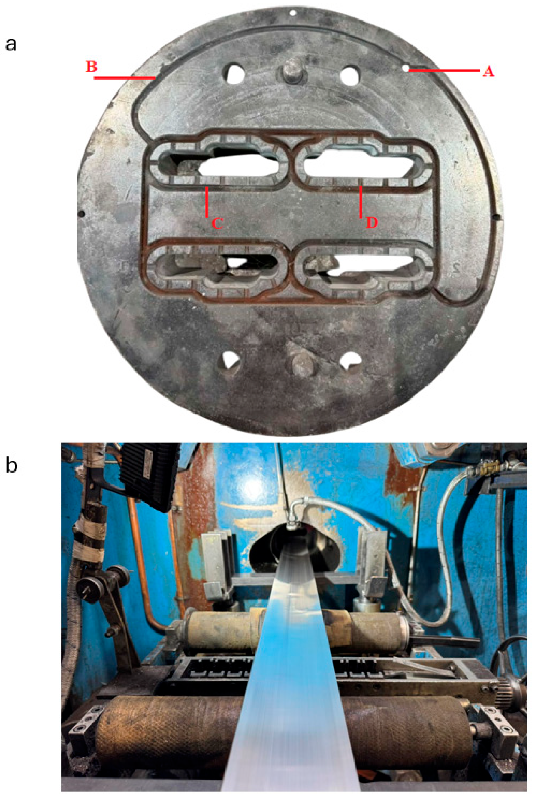
Figure 1 illustrates the methodology applied in this research. The material selected for investigation is the 6060 aluminum alloy, with its elemental composition detailed in Table 1. The samples were measured through an Optical Emission Spectrometer (OES) FOUNDRY MASTER COMPACT from Hitachi (Uedem, Germany). To produce suitable specimens for testing, the material was extruded using a 37.5 MN Danieli Breda (Buttrio (UD), Italy)Extrusion Press. The exit temperature of the extrudates was consistently measured at 520 °C, regardless of the ram speed. This consistency was achieved by carefully monitoring the billet’s preheating temperature and using liquid nitrogen as a cooling agent to keep the exit temperature the same, even at higher ram speeds. The software N5NITROGEN (a part from the Extrusion Management System (EMS) version 3) from ATIEUNO (Lecco, Italy) and the AXEDA 6.0 SCADA control system from the extrusion press ensure the smooth running of the whole operation. After the extrusion process, the extrudates were subjected to ageing at 180 °C for 1 h, 4 h and 8 h, respectively. Cooling channel design in aluminum extrusion dies is largely guided by empirical methods, given the challenges associated with modelling multiphase flow and variable heat transfer. To ease the design process and minimize computational inaccuracies, manufacturers typically rely on practical design standards. These simplified principles offer an economical solution for developing effective cooling systems. Figure 2a illustrates the configuration of nitrogen-based cooling channels in the aluminum extrusion die used to produce the samples for this study, while Figure 2b depicts the extrusion operation and the resulting extrudates. In this setup, liquid nitrogen enters through inlet point (A), is distributed via the outer ring (B), and then flows through designated cooling channels (C) to reach the injectors (D). The layout of these channels is determined by factors such as the symmetry of the profile, the quantity of cooling holes, and structural limitations of the die. Although initial configurations may require iterative refinement, following these proven design principles can greatly enhance the efficiency of the cooling system [28]. The extrudates produced through this method served as the source material for the nanoindentation and tensile testing conducted in this research.

2.2. Tensile Tests

Tensile tests involve applying a force that stretches the specimen, assessing in this way the material’s ability to withstand uniaxial tensile loads. Tensile tests were conducted using a universal testing machine (M500-50AT, Testometric, Lincon, UK). The specimens for the tensile tests were prepared according to the EN ISO 6892-1:2019 [29] with a gauge length at 50 mm and a rectangular cross-section measuring 12.5 mm (± 1 mm) in width and thickness according to the extrudates geometry at 1.63 mm. The crosshead speed that was used during the tensile tests was at 5 mm/min. Five specimens were tested for each experimental condition to ensure the results reflect a representative sample of the material’s behaviour.

2.3. Nanoindentation Testing Supported by Finite Element Analysis

Nanoindentation experiments were carried out at ambient temperature using the DUH-211S instrument from Shimadzu (Kyoto, Japan), which offers a load resolution of 0.196 μN. A Berkovich diamond indenter, characterized by its three-sided pyramidal shape with a triangular projection, a 65° included angle, and a tip radius of 100 nm, was employed for the measurements. During the nanoindentation testing, a controlled load with a peak of 800 mN was applied through the diamond tip to the surface and cross-section of the specimens at the upper end of nanoindentation and held for 3 s. The applied force was intentionally chosen to penetrate sufficiently into the aluminum, ensuring that any superficial surface unevenness was addressed. At this depth, a greater volume of precipitates is engaged, allowing for a more accurate assessment of the bulk material’s mechanical behaviour. The indentation depth was recorded as a function of load, and the indenter was then unloaded to zero load. During the creep time, the maximum indentation load was maintained. The average value of ten measurements was used to calculate the elastic modulus and hardness.
The elastic modulus and indentation hardness of the specimens were evaluated using the Oliver and Pharr calculation method [30]. The hardness (H) was derived by incorporating the maximum depth of indentation into the calculation function:
H = P m a x A
where Pmax represents the maximum load applied, measured at the deepest penetration point (hmax), while A represents the projected contact area between the surface and the indenter. For an ideal Berkovich indenter, A can be calculated as a function of the contact indentation depth (hf) as follows:
A = 33 3 h f 2 tan 2 65 = 23.96 h f 2
The contact indentation, known as hf, can be calculated using the given formula:
h f = h m a x ε P m a x s
where ε represents a geometric constant with a value of 0.75 for a pyramidal indenter, while S is the contact stiffness. The contact stiffness (S) is calculated as the gradient of the unloading curve at the point of maximum applied load, as expressed below:
s = d P d h h = h m a x
The elastic modulus E is given by:
Ε = S 2 β π A
where β is a constant determined by the indenter’s shape. For the Berkovich indenter used in this study, β is set to 1.034. Subsequently, the elastic modulus of the specimen (Es) can be calculated using the following formula:
1 Ε = 1 v s 2 E s + 1 v i 2 E i
where Ei,s and vi,s correspond to the elastic modulus and Poisson’s ratio, respectively. For a diamond indenter, the elastic modulus (Ei) is 1140 GPa, and the Poisson’s ratio (vi) is 0.07. The specimen’s hardness (H) and elastic modulus (Es) are determined using the previously outlined equations.
This instrumented technique enables the precise measurement of the local discrepancies of elastic modulus and hardness over the surface of the specimens [31,32,33].
Finite element analysis (FEA) was applied to align the nanoindentation test curves and derive the stress–strain characteristics by comparing aluminum alloy samples subjected to varying ram speeds, specifically, higher speeds with liquid nitrogen cooling and lower speeds without it. The interaction between the indenter and the specimen surface was represented using contact elements. The loading phase of the indenter’s penetration was simulated to replicate the nanoindentation tests computationally. Prior research [34,35] has shown that incorporating kinematic hardening enhances the convergence rate of FEA simulations, which is why this method was adopted for the curve-fitting process. The model incorporates a symmetrical boundary condition along the left edge to reduce computational complexity, while the bottom edge of the specimen is fully constrained to prevent any movement. A vertical displacement is applied to the indenter, which interacts with the specimen through contact elements. Additionally, the reaction force is computed at the bottom support to evaluate the mechanical response of the material.

2.4. Fractographic and Metallographic Assessment Methods

An in-depth fractographic analysis was carried out on the selected 6060 aluminum alloy subjected to severe ageing treatments for one hour and eight hours at 180 °C. This study employed Phenom ProX scanning electron microscopy (SEM) (ThermoFisher Scientific, Waltham, MA, USA) and imaging methods to assess the effects of these ageing conditions on the material’s microstructure. Additionally, metallographic evaluation was conducted. The sample preparation process involved several meticulous steps. The specimens were initially embedded using cold mounting resins, followed by grinding with silicon carbide (SiC) papers of progressively finer grit sizes (320, 800, and 1200). Polishing was then performed using soft cloths and diamond pastes of 3 µm and 1 µm for six minutes. The final polishing step utilized an Oxide Polishing Suspension (OPS) solution for four minutes to achieve the desired surface finish.

3. Results and Discussion

3.1. Production Data

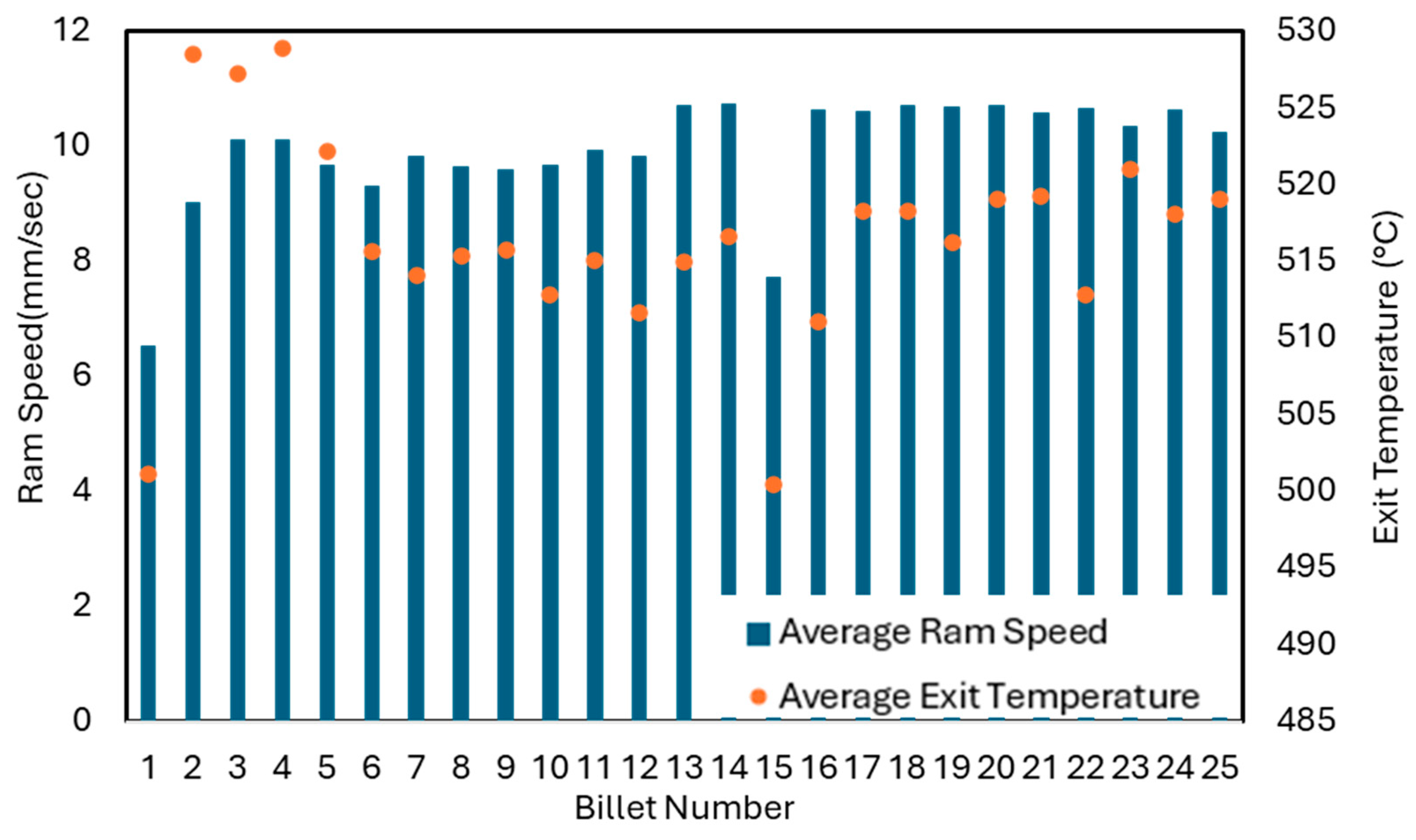
Figure 3 illustrates the progress of the average ram speed and the exit temperature of the extrudates. Twenty five billets have been extruded for the aims of this experiment. Table 2 presents the billet length and temperature parameters relevant to the objectives of this study. Zones 1 through 3 correspond to the initial three positions along the billet, where temperature measurements are taken to enable thermal regulation of the extrusion process. The tenth billet has been selected in order to start the liquid nitrogen use. The significant increase in the ram speed did not affect the exit temperature of the extrudates due to the use of liquid nitrogen as a cooling agent as Figure 3 outlines. The liquid nitrogen use resulted in an increase in the average ram speed of 15.25% (from 9.31 mm/s to 10.73 mm/s).

3.2. Tensile Test Results

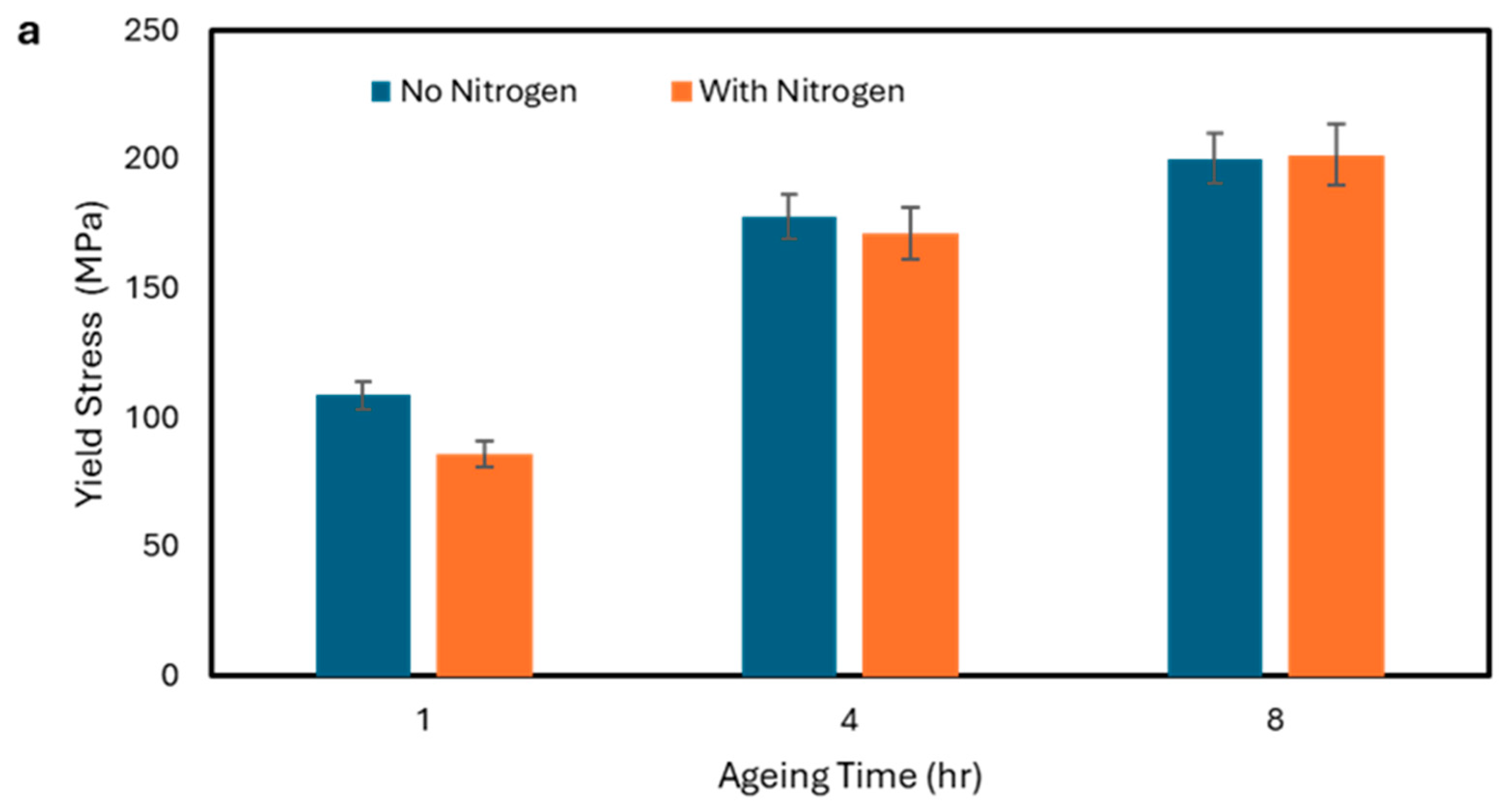
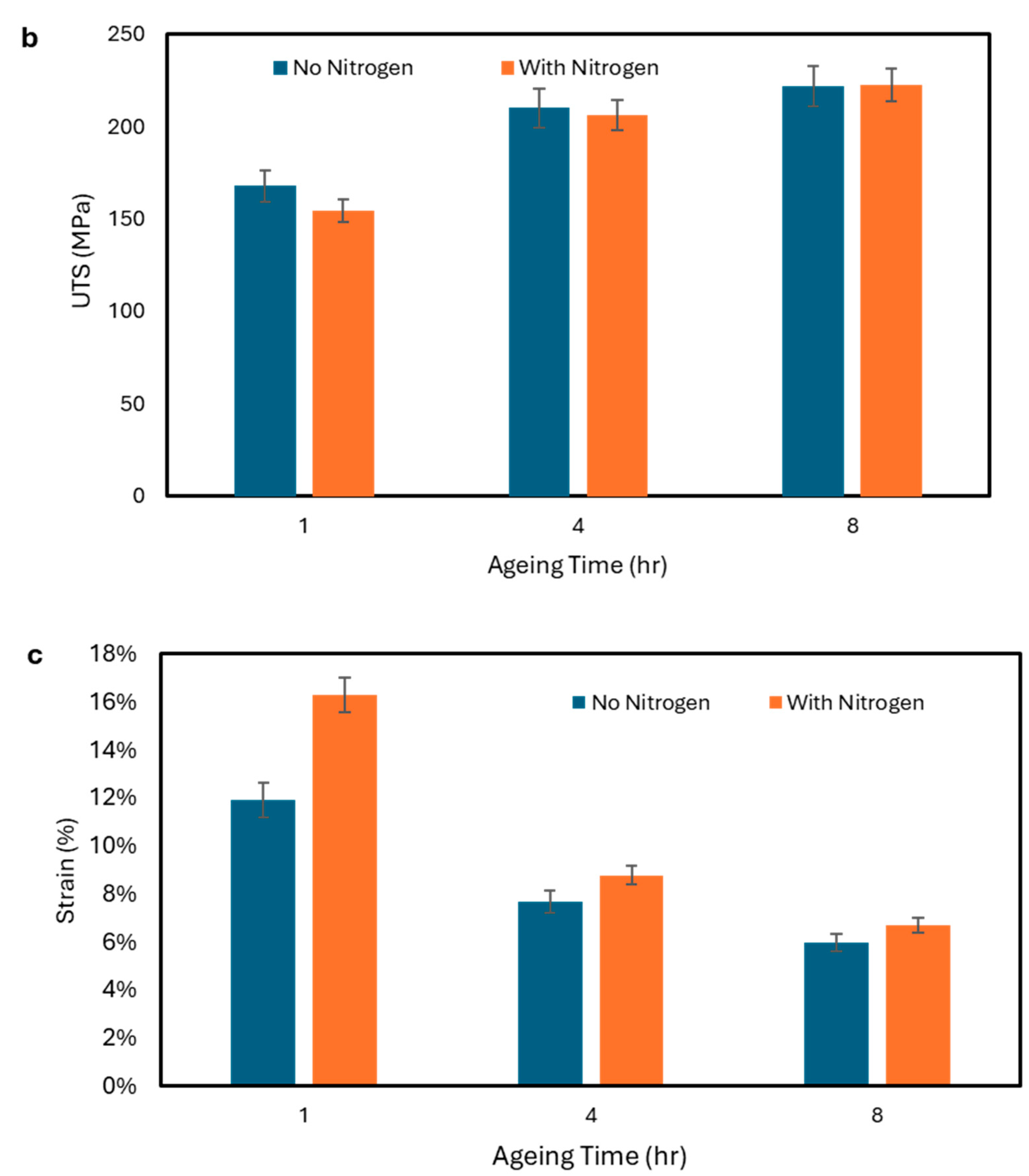
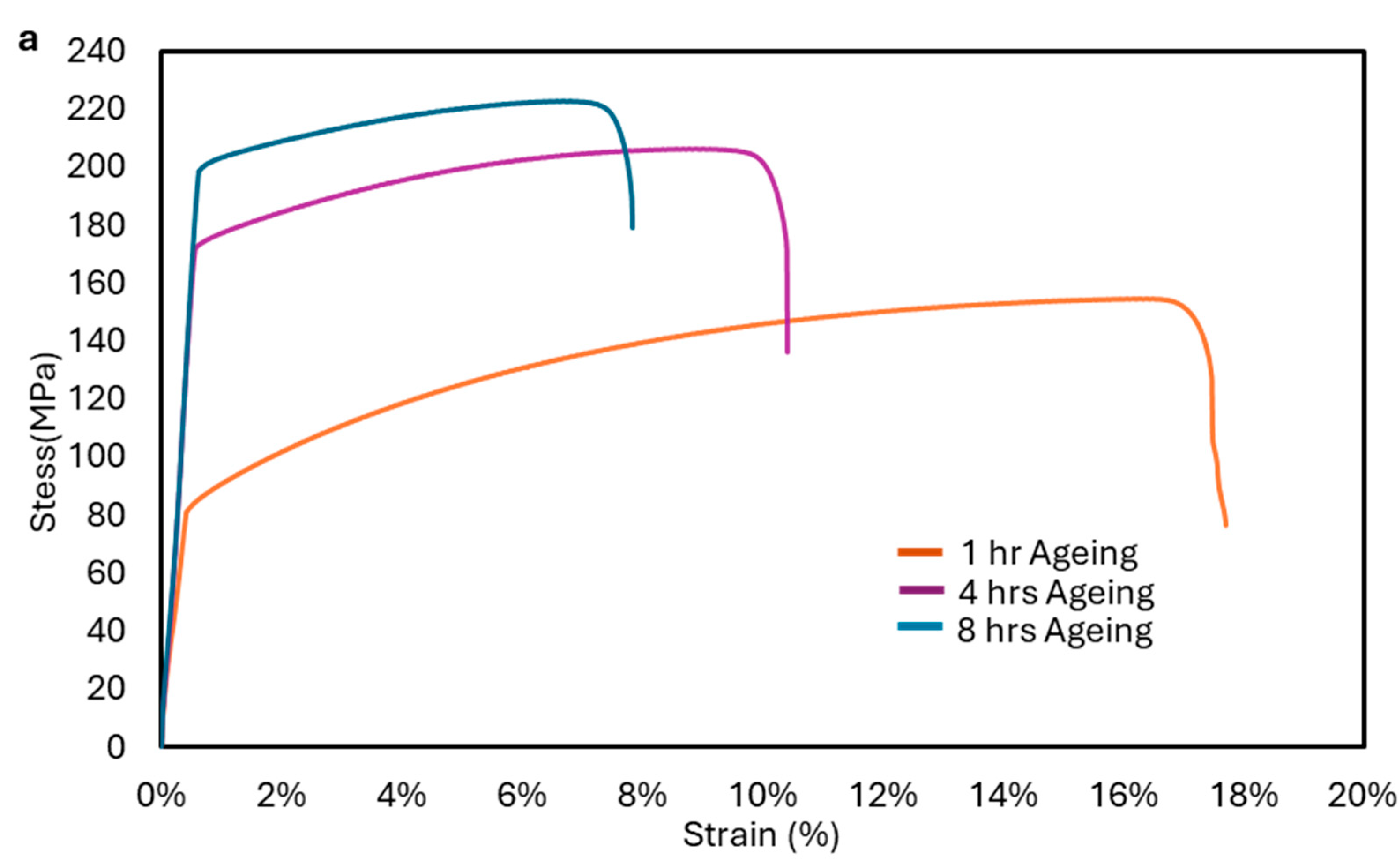
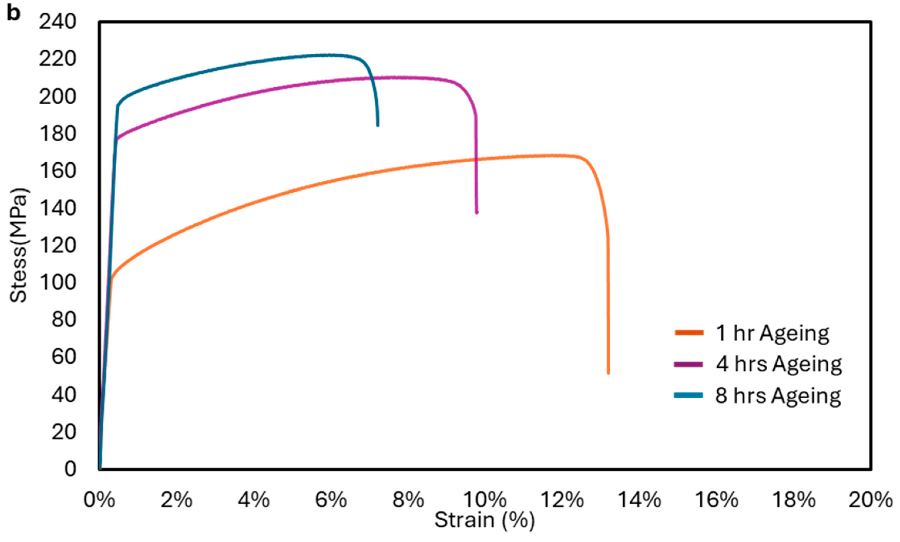
Figure 4 and Figure 5 show the tensile test results, where the use of liquid nitrogen as a cooling agent seems to have no important effect on the yield stress for an ageing temperature of 180 °C. Figure 5 displays a typical stress–strain curve chosen to illustrate the average values presented in Figure 4. Moreover, for the ageing temperature of 180 °C, it seemed that ageing after 4 h had no significant effect on yield stress. A small increase in the YTS by 0.72% has been found for the ageing for 8 h at 180 °C, due to the use of liquid nitrogen as coolant and the higher ram speeds. Furthermore, the use of liquid nitrogen as a cooling agent seems to have no important effect on the UTS. Moreover, it appeared that ageing after 4 h has no significant effect on UTS. A small increase in the UTS by 0.20% has been found for the ageing for 8 h at 180 °C, due to the use of liquid nitrogen as coolant and the higher ram speeds. However, the use of liquid nitrogen as a cooling agent appears to have some effect on the strain (%) at UTS for ageing temperatures of 180 °C. At greater ageing temperatures, these effects seemed to be smaller, due to the possibility of the faster formation of bigger Mg2Si precipitates. More specifically, the increased ram speed using liquid nitrogen as a cooling agent resulted in an increase in strain (%) at UTS by 36.9%, 14.6% and 12.1% for 1 h, 4 h, and 8 h of ageing at 180 °C, respectively. This suggests that while strength parameters remained relatively stable, ductility was significantly enhanced. The increased strain may be attributed to refined microstructural features induced by higher ram speeds, such as finer precipitate distribution or suppressed coarsening of Mg2Si particles. These findings highlight the potential of liquid nitrogen cooling to tailor mechanical properties—particularly ductility—without compromising strength. Further microstructural analysis in the future would be beneficial to elucidate the mechanisms behind this strain enhancement.

3.3. Fractographic and Metallographic Characterization

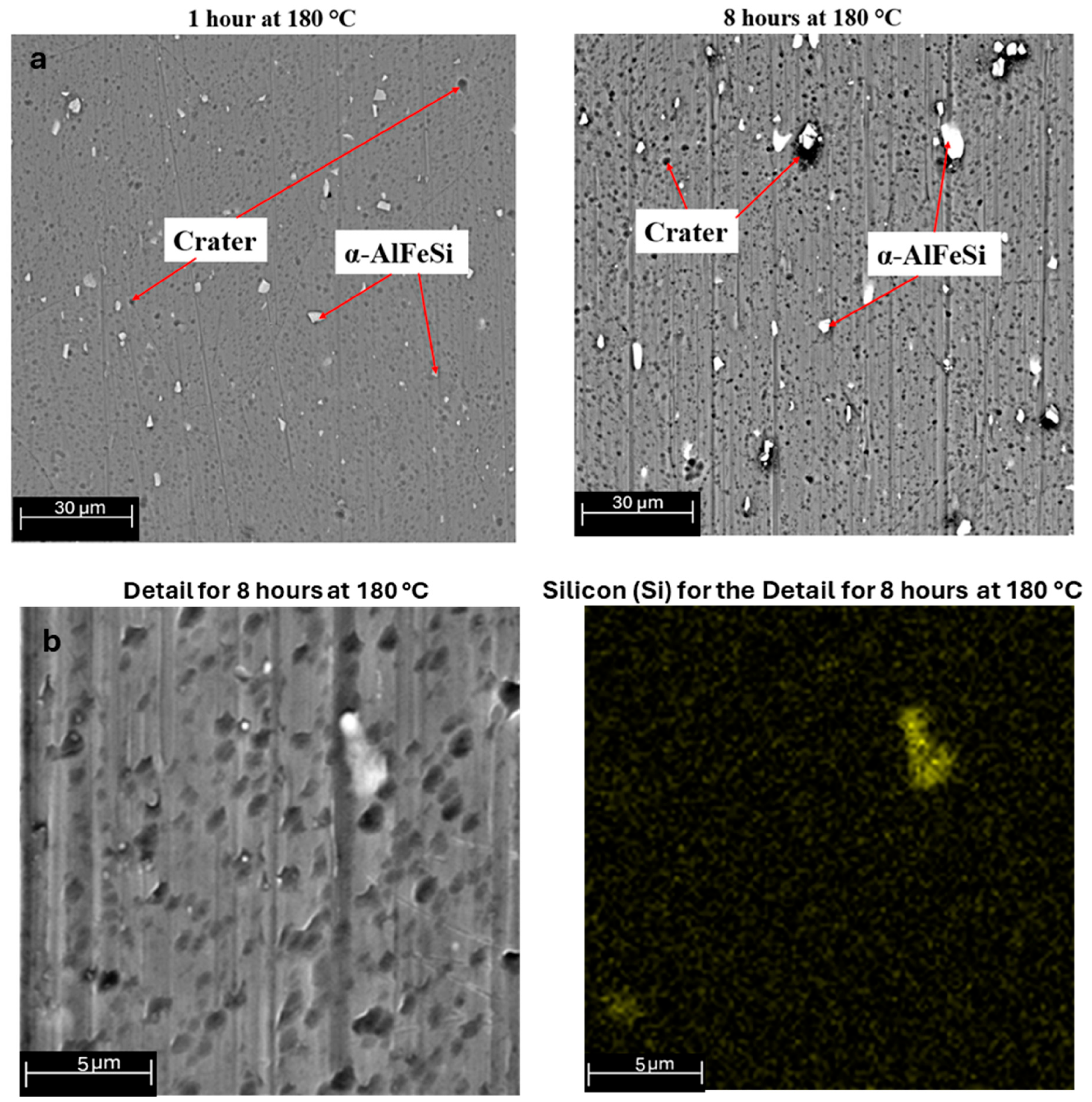
A comprehensive fractographic examination was conducted on tensile specimens corresponding to the maximum ageing conditions (1 h at 160 °C and 8 h at 180 °C). Figure 6a illustrates typical ductile failure, characterized by micro-void coalescence. It is evident that with increased ageing conditions, the voids become fewer and larger compared to those in less aged material. Additionally, there is a notable increase in the number of dimple regions on the surface of the peak-aged specimen, attributed to the presence of more precipitates that promote the formation of these regions. Figure 6b reveals more transgranular brittle fractures of particles on the surface, forming shallow dimples of varying sizes due to the higher strength at theses ageing conditions. Furthermore, the metallographic examination of the two ageing conditions has also been performed. Figure 7a provides a visual representation of the α-AlFeSi particles, which are observed to be smaller and have an aspect ratio close to one with smoother edges under the lower ageing condition. Figure 7b illustrates the EDX mapping of the detailed image for the material aged for 8 h at 180 °C. The element Si was selected to confirm that the white spots are α-AlFeSi particles.

3.4. Nanoindentation Test Results

Load-Depth Curves

Figure 8 illustrates the load-depth behaviour at an ageing temperature of 180 °C for three distinct ageing cycles, comparing higher ram speed (utilizing liquid nitrogen) with lower ram speed (without liquid nitrogen). It is evident that hardness increases with longer ageing time as the penetration depth is decreasing. Furthermore, the nanoindentation results show that increasing the ram speed—achieved through liquid nitrogen cooling—leads to a slight reduction in hardness after 1 and 4 h of ageing, and a minimal reduction after 8 h. Specifically, extrudates processed at higher ram speeds exhibited an increase in maximum indentation depth of 6.2% and 2% for 1 h and 4 h ageing durations, respectively. For the 8 h ageing cycle, the increase in maximum depth was only 1%. This figure presents a more detailed analysis of data obtained from our prior research [28].

3.5. Finite Element Analysis Results

The force-depth curves of the aluminum alloy specimens with higher and lower ram speed at 4 h were used as input for the developed computational model. An axisymmetric FEA model was developed, where multilinear stress–strain curves were iteratively adjusted until the computed force response matched the experimental curves. The model boundary conditions replicated the experimental setup; the bottom surface of the specimen was fixed and the experimental indentation depth was step-applied to the model’s indenter as an imposed displacement, while the corresponding force reaction was computed and compared to the measured values.
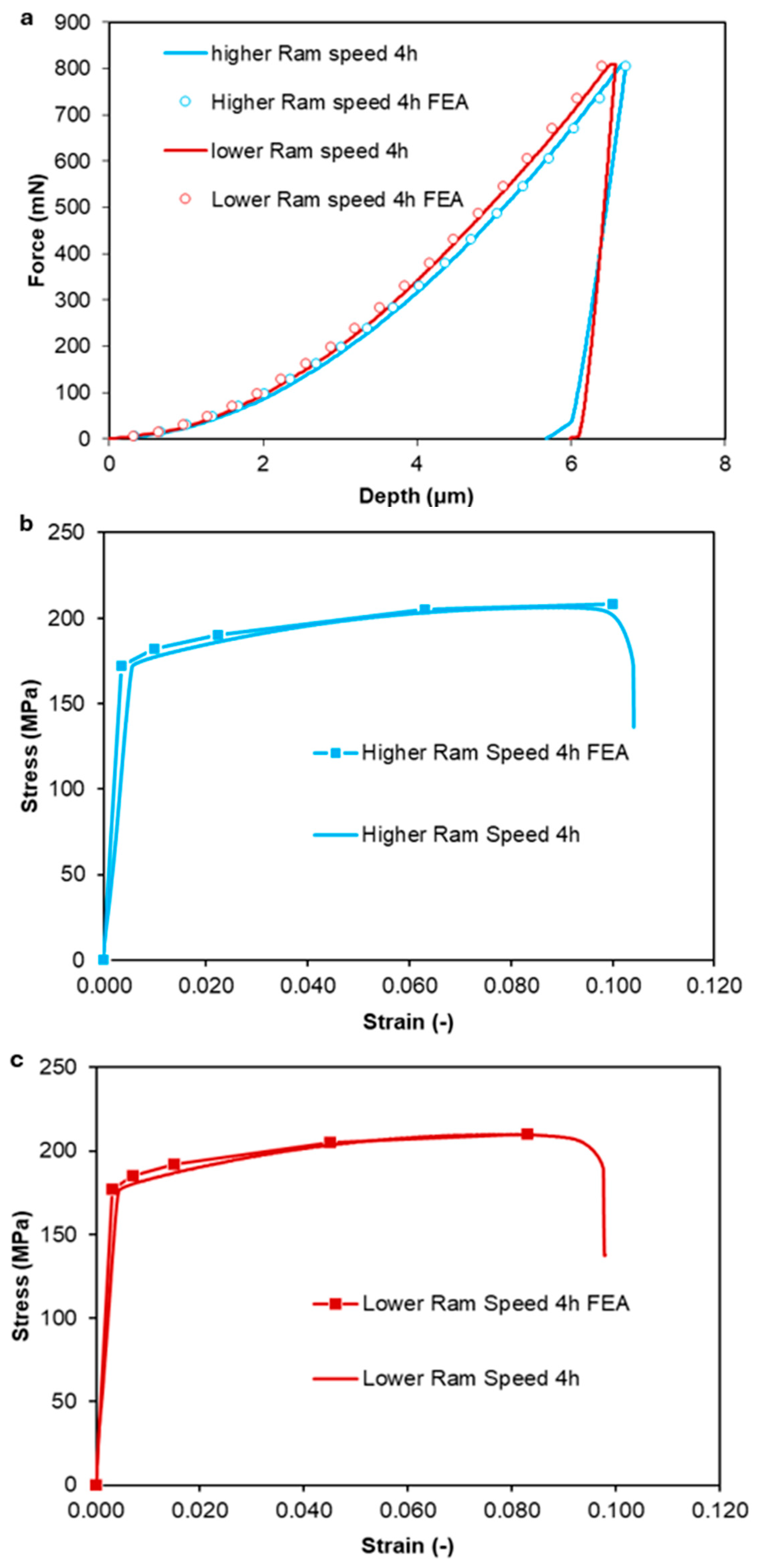
The initial force applied and its corresponding penetration depth were first analyzed. The elastic modulus was directly derived from the nanoindentation results and served as the starting tangent modulus for the specimen’s stress–strain profile. The experimentally obtained indentation depth was incrementally applied to the model’s indenter, and the resulting reaction force was calculated and compared with the measured data. In the simulations, the maximum indentation depth reached 6.72 μm for aluminum alloy samples tested at both high and low ram speeds. If the force predicted by the FEA did not align with the experimental values, the tangent modulus was recalculated. When the simulated force matched the measured force, the tangent modulus was validated, and the next set of force and depth values was introduced into the model. Each new computation began from the previous indentation depth, incorporating the existing stress state and the last accepted tangent modulus. This iterative procedure continued until the final load-depth pair achieved convergence, completing the cycle. Computationally generated force–depth curves are presented in Figure 9a, showing good correlation between the measured nanoindentation tests and the simulation results for both higher and lower ram speed aluminum alloy specimens. At least 20 simulation steps were required to achieve converged FEA solutions and satisfactorily reproduce the nanoindentation curves. Beyond fitting the experimental data, the FEA framework enables the reconstruction of constitutive stress–strain curves directly from nanoindentation force–depth results. This provides an efficient methodology to estimate material behaviour under different ram speed conditions and can be extended to other alloys or processing parameters where extensive tensile testing is impractical.
The corresponding stress–strain behaviour was deduced by optimizing the curve-fitting results of the nanoindentation data. The FEA results revealed that the aluminum alloy specimen with lower ram speed exhibited a higher elastic modulus (55,659 MPa) compared to the higher ram speed specimen (49,740 MPa). Similarly, the experimentally determined indentation modulus was higher for the lower-ram-speed sample (51,920 MPa) compared to the higher-ram-speed sample (50,350 MPa), confirming that decreasing the ram speed leads to increased stiffness and strength. Figure 9b,c illustrates the FEM-extracted stress–strain laws for both aluminum alloy specimens, demonstrating that the lower ram speed resulted in a moderate increase in strength. These results indicate that the ram speed significantly influences the mechanical properties of aluminum alloys. The lower-ram-speed specimen exhibited a higher elastic modulus and overall strength compared to the higher-ram-speed specimen, suggesting that processing conditions play a crucial role in defining the material’s stress–strain response. Based on these findings, it can be concluded that the experimental nanoindentation technique, combined with FEA, is an effective method for determining the mechanical behaviour of aluminum alloys under varying ram speed conditions. The ageing cycle of 4 h was selected because it meets the minimum mechanical performance requirements specified in EN 755-2:2016 [36].

3.6. Nanoindentation Creep Behaviour

To investigate creep behaviour through nanoindentation testing, the data obtained during the holding phase of the experiment were evaluated. The measurements recorded in this stage were accurately fitted using the following equation [27]:
h = hi + a(t − ti)1/2 + b(t − ti)1/4 + c(t − ti)1/8
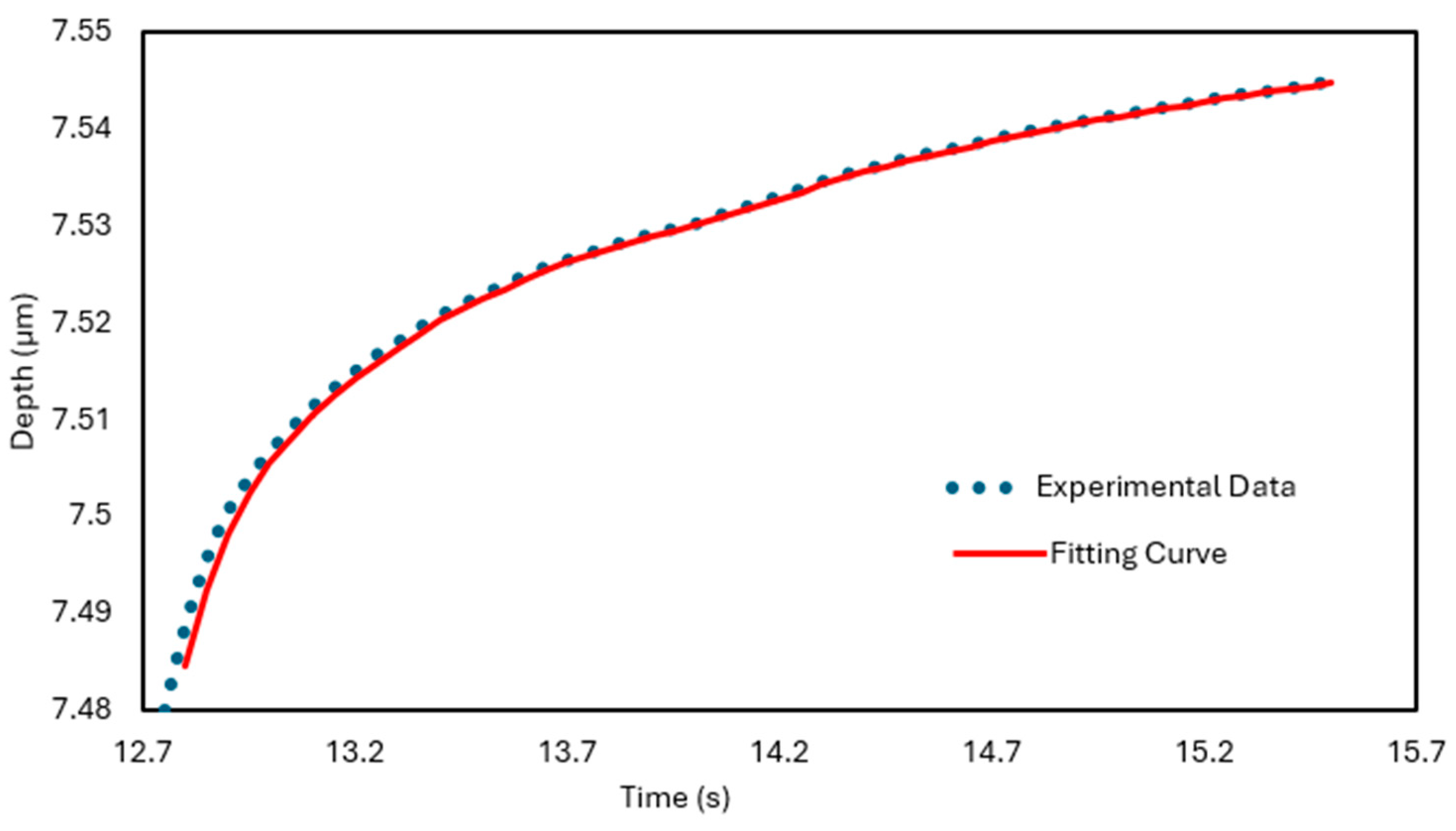
where h is the indenter displacement during the holding stage, t represents the creep time, and hi, ti, a, b and c are the parameters obtained through curve fitting. Figure 10 illustrates the experimental creep displacement data over time for a sample aged at 180 °C for one hour, obtained during the holding stage of the nanoindentation test. The red curve corresponds to the fitted model described by Equation (7), while the blue markers represent the actual experimental measurements. The onset of the holding phase was designated as the origin of the x-axis to accurately define the time window for creep analysis. Table 3 lists the optimized fitting parameters derived from Equation (7). The results clearly show a strong correlation between the fitted curve and the experimental data for the room-temperature creep behaviour of the 6060 aluminum alloy during nanoindentation. The fitting parameters were computed using Gnuplot (http://www.gnuplot.info/), a versatile command-line graphing tool, based on the experimental dataset and in accordance with Equation (7).
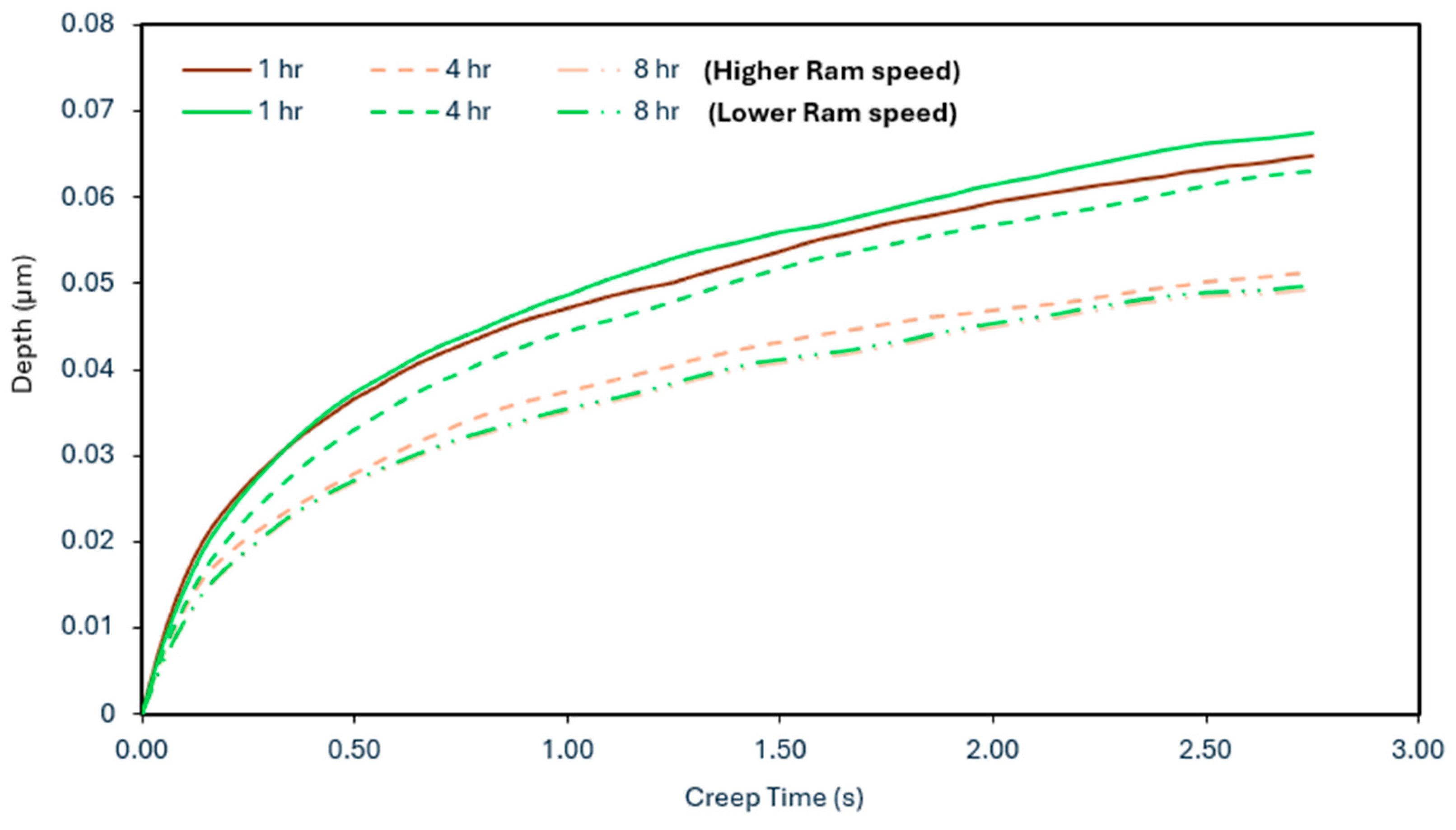
Figure 11 shows the creep displacement-time curves during the nanoindentation creep at an ageing temperature of 180 °C for three distinct ageing cycles, comparing higher ram speed (utilizing liquid nitrogen) with lower ram speed (without liquid nitrogen). In contrast with the load-depth graph (Figure 8), concerning creep displacement, it seems that for all ageing cycles at 180 °C, the higher ram speeds (with liquid nitrogen as the coolant) result in lower creep displacement from the start until the end of the holding stage. Furthermore, it is evident that by increasing the ageing time the creep displacement is decreased.
Based on the aforementioned results, it is important to note that the use of liquid nitrogen as a cooling agent, and the resulting increased ram speeds, do not significantly impact the maximum depth during the nanoindentation test. However, there is evidence suggesting that the creep behaviour may be affected, as smaller creep displacements were observed in all experiments. It is possible that a more significant impact on these findings might be observed in stronger alloys, such as 6005 or 6082.
As reported by Mayo et al. [37], the creep strain rate ε ˙ was derived from displacement data using the following mathematical expression:
ε ˙ = h ˙ h   =   1 h d h d t
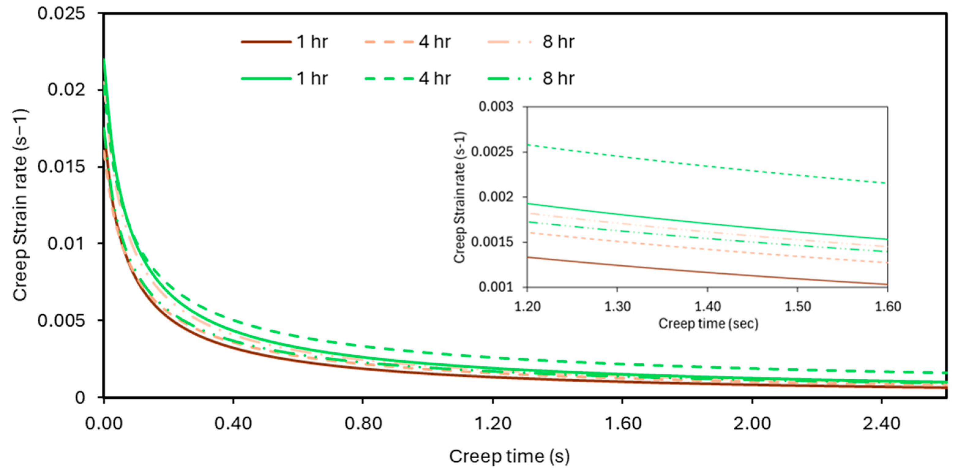
The creep strain rate was derived by differentiating the fitted displacement-time (h–t) curves obtained during the holding phase, as described by Equation (7). Figure 12 presents the comparative results for extrusion processes conducted with and without liquid nitrogen cooling of the dies. The resulting ε ˙ –t curves display two distinct phases: an initial transient stage followed by a steady-state phase. For calculating the creep stress exponent, only the steady-state region is considered, as its value fluctuates across different points on the creep strain rate versus hardness (H) plot. At the beginning of the holding period, a notably high creep strain rate was recorded, which then declined sharply and stabilized at minimal levels after approximately 2.4 s—hence the x-axis cutoff in the figure. Similar observations have been documented in prior research [27]. This behaviour is likely attributed to work hardening from plastic deformation and precipitate accumulation, characteristic of the transient creep phase. Beyond 3 s of holding time, the material enters a near steady-state creep regime, with the strain rate decreasing gradually due to the interplay between work hardening and dynamic recovery mechanisms [38]. Figure 13 shows that incorporating liquid nitrogen as a cooling medium does not significantly alter the creep strain rate progression. Each figure includes detailed visuals that emphasize the distinctions between different ageing treatments. The prevailing creep mechanism and the material’s behaviour under ambient-temperature conditions can be analyzed using Equation (9), which relates stress (σ) to the creep strain rate ( ε ˙ ) [39]:
ε ˙ = α σ n
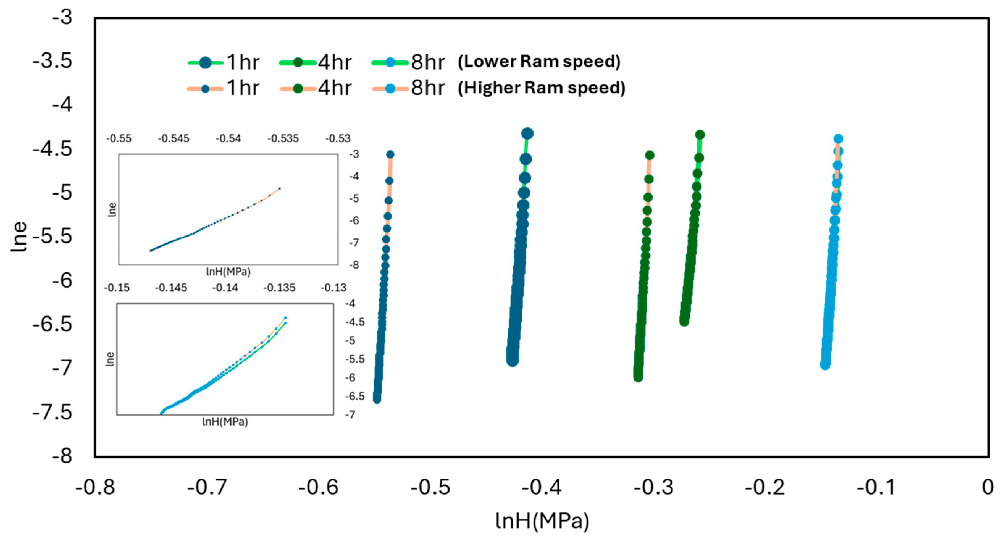
where n represents the creep stress exponent, and α is a material-specific constant. During nanoindentation testing, the applied stress is associated with the pressure exerted by the indenter. Using the relationship H = P/A = P/24.56hc2, where P is the holding load and A is the projected contact area of the Berkovich indenter, the creep stress during the holding phase can be approximated by σ = (H/3)/(hmax/h)2 [40]. Furthermore, the value of the creep stress exponent n is obtained by calculating the slope of the plot of ln ε ˙ versus lnH, as described in Equation (10).
n = d ( l n ε ˙ ) d ( l n H )
Figure 13 displays the plots of ln ε ˙ versus lnH, constructed using the defined relationships between creep strain rate and stress, both with and without liquid nitrogen cooling applied to the extrusion dies. To determine the creep stress exponent for each specimen (based on varying ageing durations) only the steady-state creep region is considered, as the exponent value fluctuates across different segments of the creep strain rate versus stress curve. The figure includes two detailed visuals that emphasize the slopes of the plotted ln ε ˙ versus lnH curves for all conditions examined.
Figure 14 presents the steady-state creep strain rate ( ε ˙ ) and creep stress exponent (n) for various ageing conditions, both with and without the application of liquid nitrogen cooling during extrusion. The steady-state strain rate remains relatively unchanged across different ageing durations, with values so low that they are highly susceptible to fluctuations, making firm conclusions difficult to establish. The creep stress exponent (n) serves as an indirect indicator of a material’s susceptibility to creep deformation—higher values typically suggest greater resistance to creep. In many instances, the value of n helps characterize the dominant creep mechanism. The results obtained in this study align with previously reported experimental data [41,42,43,44,45,46,47]. Notably, increasing the ram speed with liquid nitrogen cooling does not significantly affect the value of n. However, extended ageing durations of 4 and 8 h result in elevated creep stress exponents at 12.59% and 26.43% for lower ram speeds, and 12.19% and 25.59% for higher ram speeds.
Some important remarks that derive from all the results presented above are as follows. The creep displacement is significantly reduced as the metal strengthens due to increased ageing, and similarly, the creep stress exponent n increases. This trend explains the shape observed in Figure 11 and Figure 14b. Under the experimental conditions (relatively short holding time of 3 s and large preset depth of 5–6 μm), the creep strain rate is numerically very low. The selected experimental conditions also contribute to the slightly elevated value of n, and thus the creep strain rate cannot be reliably evaluated. Generally, as n increases, the creep strain rate tends to decrease; however, under our specific conditions, this behaviour is not typical. The same findings are presented by Karantzalis et al. [45]. With longer holding times or smaller preset depths at maximum loading, n tends to decrease, potentially making the creep strain rate more sensitive. The above results present great interest in future research. It is possible that the precipitation hardening effect in combination with the applied stresses may lead to the above findings as during higher applied stresses, the dominant creep mechanism shifts to dislocation creep and thus the interaction between the precipitates during the experiment contribute to these characteristics [48].

4. Conclusions

The 6060 aluminum alloy was chosen for the current study to investigate the impact of increased extrusion ram speed, facilitated by the use of liquid nitrogen as a die cooling agent, on the mechanical performance of the alloy. The mechanical behaviour of the extruded sections was assessed through tensile and nanoindentation tests. Additionally, the creep behaviour and relevant parameters, such as steady creep strain rate, were examined using nanoindentation tests. The presented results indicate that for the tensile tests, ageing at 180 °C for 4 h does not significantly affect the ultimate tensile strength (UTS) and yield tensile strength (YTS). The use of liquid nitrogen as a cooling agent appears to have a minimal impact on UTS and YTS for the ageing of 8 h at 180 °C, with only slight increases of 0.2% and 0.72%, respectively. However, liquid nitrogen cooling does influence the strain at UTS for ageing at 180 °C, with increased ram speeds resulting in strain increases of 36.71%, 24.76%, and 16.94% for 1 h, 4 h, and 8 h of ageing, respectively. Regarding the nanoindentation tests, the maximum displacement of the indenter decreases with longer ageing times at 180 °C. Liquid nitrogen cooling of the die does not significantly affect the maximum displacement during these tests. Higher ram speeds with liquid nitrogen cooling result in lower creep displacement throughout the holding stage, and increased ageing time further reduces creep displacement. The steady creep strain rate remains relatively unchanged with ageing, but the creep stress exponent (n) increases with longer ageing times at 180 °C. Specifically, ageing for 4 and 8 h increases the creep stress exponent by 12.59% and 26.43% at lower ram speeds, and by 12.19% and 25.59% at higher ram speeds. These findings may have a more pronounced impact on stronger alloys due to their quench sensitivity. An important finding of the present research is the fact that the strain seems to be importantly affected by the increased extrusion ram speeds (with the liquid nitrogen as cooling agent). In addition, the higher ram speeds (with the use of liquid nitrogen as a coolant) give lower creep displacement throughout the holding stage. Furthermore, it is evident that by increasing the ageing time, the creep displacement is also decreased. Moreover, the experimental nanoindentation technique, coupled with finite element analysis (FEA), has proven to be an effective method for assessing the mechanical behaviour of aluminum alloys under different ram speed conditions. The findings demonstrate that ram speed significantly affects the mechanical properties of aluminum alloys. Specifically, specimens processed at lower ram speeds exhibited higher elastic modulus and overall strength compared to those processed at higher ram speeds. This underscores the critical role of processing conditions in shaping the material’s stress–strain response. For many aerospace and automotive applications this behaviour is of great importance, so further research efforts should target the assessment of harder alloys such as 6063, 6005 and 6082 to examine if a similar relationship to that of the 6060 alloy exists.

Author Contributions

Conceptualization, E.G. and D.T.; methodology, E.G. and D.T.; software, K.T. and A.K.; validation, E.G., E.T. and C.D.; formal analysis, E.G., K.T., A.K., C.D. and D.T.; investigation, E.G. and E.T., resources, E.G., A.K., C.D. and D.T. data curation, E.G., E.T., K.T., A.K., C.D.; writing—original draft preparation, E.G. and E.T.; writing—review and editing, K.T., A.K., C.D. and D.T.; visualization, E.G., E.T., K.T., A.K., C.D. and D.T.; supervision, D.T.; project administration, D.T. All authors have read and agreed to the published version of the manuscript.

Funding

This research received no external funding.

Data Availability Statement

The original contributions presented in this study are included in the article. Further inquiries can be directed to the corresponding author.

Conflicts of Interest

Author Evangelos Giarmas was employed by the company Alumil S.A. The remaining authors declare that the research was conducted in the absence of any commercial or financial relationships that could be construed as a potential conflict of interest.

References

  1. Gagliardi, F.; Ciancio, C.; Ambrogio, G. Optimization of porthole die extrusion by Grey-Taguchi relational analysis. Int. J. Adv. Manuf. Technol. 2018, 94, 719–728. [Google Scholar] [CrossRef]
  2. Bakhtiani, T.; El-Mounayri, H.; Zhang, J. Modeling of extrusion process of a condenser tube for investigating the effects of mandrel geometry. Int. J. Adv. Manuf. Technol. 2017, 92, 3237–3252. [Google Scholar] [CrossRef]
  3. Iqbal, U.M.; Kumar, V.S.S.; Gopalakannan, S. Application of Response Surface Methodology in optimizing the process parameters of Twist Extrusion process for AA6061-T6 aluminum alloy. Measurement 2016, 94, 126–138. [Google Scholar] [CrossRef]
  4. Wu, Y.; Liao, H. Corrosion Behavior of Extruded near Eutectic Al–Si–Mg and 6063 Alloys. J. Mater. Sci. Technol 2013, 29, 380–386. [Google Scholar] [CrossRef]
  5. Zhan, H.; Mol, J.M.C.; Hannour, F.; Zhuang, L.; Terryn, H.; De Wit, J.H.W. The influence of copper content on intergranular corrosion of model AlMgSi(Cu) alloys. Mater. Corros. 2008, 59, 670–675. [Google Scholar] [CrossRef]
  6. Zang, R.; Ning, Y.; Ding, L.; Jia, Z.; Xiang, K.; Liu, Q.; Cao, L.; Li, Y. Study on properties and precipitation behavior of 6000 series alloys with high Mg/Si ratios and Cu contents. Mater. Charact. 2022, 194, 112402. [Google Scholar] [CrossRef]
  7. Lesniak, D.; Gromek, P. Estimation of extrusion welding conditions for 6xxx aluminum alloys. Procedia Manuf. 2020, 47, 253–260. [Google Scholar] [CrossRef]
  8. Hannard, F.; Pardoen, T.; Maire, E.; Le Bourlot, C.; Mokso, R.; Simar, A. Characterization and micromechanical modelling of microstructural heterogeneity effects on ductile fracture of 6xxx aluminium alloys. Acta Mater. 2016, 103, 558–572. [Google Scholar] [CrossRef]
  9. Mróz, A.; Mania, R.J. The complex influence of aluminium aging on the dynamic response of the thin-walled AL-6060 alloy profil. Thin-Walled Struct. 2014, 79, 147–153. [Google Scholar] [CrossRef]
  10. Ammu, V.; Raju, I.; Chouhan, R.N.; Agnihotri, A. Effect of ram speed on surface quality and mechanical properties during extrusion of AA2024 alloy. Mater. Today Proc. 2024, 113, 258–263. [Google Scholar] [CrossRef]
  11. Zhang, M.; Yang, C.; Li, Z.; Bao, S.; Ye, P.; Chen, Y. Effect of extrusion speed on microstructure and mechanical properties of Mg-Al-Ca-Sn alloy. Mater. Res. Express 2022, 9, 056508. [Google Scholar] [CrossRef]
  12. Li, J.; Zhang, A.; Pan, H.; Ren, Y.; Zeng, Z.; Huang, Q.; Yang, C.; Ma, L.; Qin, G. Effect of extrusion speed on microstructure and mechanical properties of the Mg-Ca binary alloy. J. Magnes. Alloy. 2021, 9, 1297–1303. [Google Scholar] [CrossRef]
  13. Zhao, Y.; Pei, J.; Guo, L.; Yun, X.; Ma, H. Effects of extrusion speed of continuous extrusion with double billets on welding performance of 6063 Al alloy. Trans. Nonferrous Met. Soc. China 2021, 31, 1561–1571. [Google Scholar] [CrossRef]
  14. Saha, P.K. Aluminum Extrusion Technology; ASM International: Materials Park, OH, USA, 2000; Chapter 2. [Google Scholar]
  15. Zasadziński, J.; Libura, W.; Richert, J. Fundamentals of Advanced Aluminum Extrusion Processes. In Proceedings of the 8th International Extrusion Technology Seminar, Orlando, Florida, 18–21 May 2004; Volume 2, pp. 391–397. [Google Scholar]
  16. Klaus, A. How to Benefit from Isothermal Extrusion. In Proceedings of the 11th International Extrusion Technology Seminar, Chicago, IL, USA, 2–6 May 2016; Volume 2, pp. 215–220. [Google Scholar]
  17. Stratton, P. Raising productivity of aluminum extrusion with nitrogen. Int. Heat. Treat. Surf. Eng. 2008, 2, 105–108. [Google Scholar] [CrossRef]
  18. Ward, T.J.; Kelly, R.M.; Jones, G.A.; Heffron, J.F. Effects of nitrogen—Liquid and gaseous—On aluminum extrusion. JOM 1984, 36, 29–33. [Google Scholar] [CrossRef]
  19. Ruppin, D.; Mueller, K. Influence of mandrel cooling in the direct extrusion of aluminum tubing using stationary or moving mandrels. Alum. Dusseld. 1982, 58, 402–406. [Google Scholar]
  20. Kim, H.H.; Cho, S.H.; Kang, C.G. Evaluation of microstructure and mechanical properties by using nano/micro-indentation and nanoscratch during aging treatment of rheo-forged Al 6061 alloy. Mater. Sci. Eng. A 2008, 485, 272–281. [Google Scholar] [CrossRef]
  21. Peng, G.; Ma, Y.; Hu, J.; Jiang, W.; Huan, Y.; Chen, Z.; Zhang, T. Nanoindentation hardness distribution and strain field and fracture evolution in dissimilar friction stir-welded AA 6061-AA 5A06 aluminum alloy joints. Adv. Mater. Sci. Eng. 2018, 2018, 4873571. [Google Scholar] [CrossRef]
  22. Ogura, T.; Ueda, K.; Saito, Y.; Hirose, A. Evaluation of interfacial microstructures in dissimilar joints of aluminum alloys to steel using nanoindentation technique. Mater. Trans. 2011, 52, 979–984. [Google Scholar] [CrossRef]
  23. Charitidis, C.A.; Dragatogiannis, D.A.; Koumoulos, E.P. A study on time dependent properties of aluminum alloy by nanoindentation technique. Int. J. Struct. Integr. 2013, 4, 33–54. [Google Scholar] [CrossRef]
  24. Chen, J.; Bull, S.J. The investigation of creep of electroplated Sn and Ni–Sn coating on copper at room temperature by nanoindentation. Surf. Coat. Technol. 2009, 203, 1609–1617. [Google Scholar] [CrossRef]
  25. Blum, W.; Li, Y.; Breutinger, F. Deformation kinetics of coarse-grained and ultrafine-grained commercially pure Ti. Mater. Sci. Eng. A 2006, 462, 275–278. [Google Scholar] [CrossRef]
  26. Chatterjee, A.; Srivastava, M.; Sharma, G.; Chakravartty, J.K. Investigations on plastic flow and creep behaviour in nano and ultrafine grain Ni by nanoindentation. Mater. Lett. 2014, 130, 29–31. [Google Scholar] [CrossRef]
  27. Liu, X.; Zhang, Q.; Zhao, X.; Yang, X.; Luo, L. Ambient-temperature nanoindentation creep in ultrafine-grained titanium processed by ECAP. Mater. Sci. Eng. A 2016, 676, 73–79. [Google Scholar] [CrossRef]
  28. Giarmas, E.; Tzimtzimis, E.; Tzetzis, D. The influence of ageing conditions and liquid nitrogen cooling of extrusion dies on nanoindentation creep in 6060 alumiium alloy. Int. J. Adv. Manuf. Technol 2025, 137, 6187–6205. [Google Scholar] [CrossRef]
  29. EN ISO 6892-1:2019; Metallic Materials—Tensile Testing. International Organization for Standardization: Geneva, Switzerland, 2019.
  30. Oliver, W.; Pharr, G. An improved technique for determining hardness and elastic modulus using load and displacement sensing indentation experiments. J. Mater. Res. 1992, 7, 1564–1583. [Google Scholar] [CrossRef]
  31. Mansour, G.; Tzetzis, D.; Bouzakis, K.D. A nanomechanical approach on the measurement of the elastic properties of epoxy reinforced carbon nanotube nanocomposites. Tribol. Ind. 2013, 35, 190–199. [Google Scholar]
  32. Tzetzis, D.; Mansour, G.; Tsiafis, I.; Pavlidou, E. Nanoindentation measurements of fumed silica epoxy reinforced nanocomposites. J. Reinf. Plast. Compos. 2013, 32, 163–173. [Google Scholar] [CrossRef]
  33. Mansour, G.; Tzetzis, D. Nanomechanical Characterization of Hybrid Multiwall Carbon Nanotube and Fumed Silica Epoxy Nanocomposites. Polym. Plast. Technol. Eng. 2013, 52, 1054–1062. [Google Scholar] [CrossRef]
  34. Tzetzis, D.; Tsongas, K.; Mansour, G. Determination of the mechanical properties of epoxy silica nanocomposites through FEA-supported evaluation of ball indentation test results. Mater. Res. 2017, 20, 1571–1578. [Google Scholar] [CrossRef]
  35. Tsongas, K.; Tzetzis, D.; Karantzalis, A.; Banias, G.; Exarchos, D.; Ahmadkhaniha, D.; Zanella, C.; Matikas, T.; Bochtis, D. Microstructural, surface topology and nanomechanical characterization of electrodeposited Ni-P/SiC nanocomposite coatings. Appl. Sci. 2019, 9, 2901. [Google Scholar] [CrossRef]
  36. EN 755-9; Aluminium and Aluminium Alloys—Extruded Rod/Bar, Tube and Profiles—Part 9: Profiles, Tolerances on Dimensions and Form. National Standards Authority of Ireland: Dublin, Ireland, 2016.
  37. Mayo, M.J.; Siegel, R.W.; Liao, Y.X.; Nix, W.D. Nanoindentation of nanocrystalline ZnO. J. Mater. Res. 1992, 7, 973–979. [Google Scholar] [CrossRef]
  38. Grote, K.H.; Antonsson, E.K. Springer Handbook of Mechanical Engineering; Springer: New York, NY, USA, 2009. [Google Scholar]
  39. Shen, L.; Cheong, W.C.D.; Foo, Y.L.; Chen, Z. Nanoindentation creep of tin and aluminium: A comparative study between constant load and constant strain rate methods. Mater. Sci. Eng. A 2012, 532, 505–510. [Google Scholar] [CrossRef]
  40. Lucas, B.N.; Oliver, W.C. Indentation power-law creep of high-purity indium. Metall. Mater. Trans. A 1999, 30, 601–610. [Google Scholar] [CrossRef]
  41. Ding, Z.Y.; Song, Y.X.; Ma, Y.; Huang, X.W.; Zhang, T.H. Nanoindentation Investigation on the Size-Dependent Creep Behavior in a Zr-Cu-Ag-Al Bulk Metallic Glass. Metals 2019, 9, 613. [Google Scholar] [CrossRef]
  42. Lin, P.; Chou, H.; Huang, J.; Chuang, W.; Jang, J.; Nieh, T. Elevated-temperature creep of high-entropy alloys via nanoindentation. MRS Bull. 2019, 44, 860–866. [Google Scholar] [CrossRef]
  43. Ma, Z.; Long, S.; Zhou, Y.; Pan, Y. Indentation scale dependence of tip-in creep behavior in Ni thin films. Scr. Mater. 2008, 59, 195–198. [Google Scholar] [CrossRef]
  44. Ma, Y.; Feng, Y.; Debela, T.T.; Peng, G.; Zhang, T. Nanoindentation study on the creep characteristics of high-entropy alloy films: Fcc versus bcc structures. Int. J. Refract. Met. Hard Mater. 2016, 54, 395–400. [Google Scholar] [CrossRef]
  45. Kang, Y.B.; Shim, S.H.; Lee, K.H.; Hong, S.I. Dislocation creep behavior of CoCrFeMnNi high entropy alloy at intermediate temperatures. Mater. Res. Lett. 2018, 6, 689–695. [Google Scholar] [CrossRef]
  46. Karantzalis, A.E.; Sioulas, D.; Poulia, A.; Mathiou, C.; Georgatis, E. A first approach on the assessment of the creep behavior of MoTaNbVxTi high entropy alloys by indentation testing. SN Appl. Sci. 2020, 2, 950. [Google Scholar] [CrossRef]
  47. Sokoli, V.; Kamnis, S.; Delibasis, K.; Georgatis, E.; Kiape, S.; Karantzalis, A.E. The Advanced Assessment of Nanoindentation-Based Mechanical Properties of a Refractory MoTaNbWV High-Entropy Alloy: Metallurgical Considerations and Extensive Variable Correlation Analysis. Appl. Sci. 2024, 14, 2752. [Google Scholar] [CrossRef]
  48. Huda, Z. Creep Behavior of Materials. In Mechanical Behavior of Materials, Mechanical Engineering Series; Springer: Berlin, Germany, 2002. [Google Scholar]
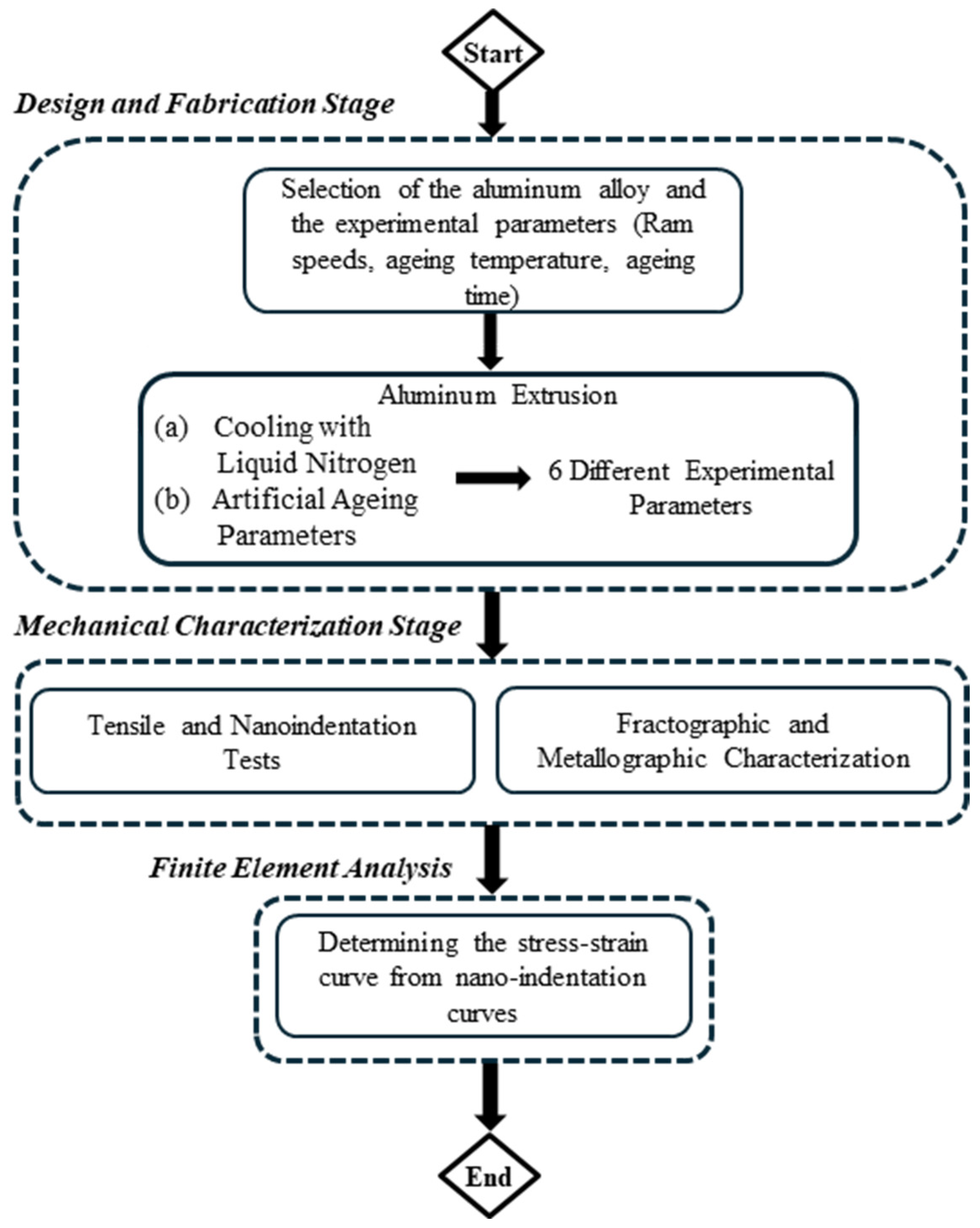
Figure 1. Flowchart of the current research.
Metals 15 01136 g001
Figure 2. (a) Liquid nitrogen channels at the aluminum extrusion die, (b) Extrudate after the extrusion process.
Metals 15 01136 g002
Figure 3. Average ram speed and exit temperature evolution for the extrudates.
Metals 15 01136 g003
Figure 4. (a) YTS, (b) UTS and (c) strain (%) at UTS for ageing at 180 °C for 1, 4 and 8 h.
Metals 15 01136 g004aMetals 15 01136 g004b
Figure 5. Tensile tests for ageing at 180 °C: (a) higher ram speed and (b) lower ram speed.
Metals 15 01136 g005aMetals 15 01136 g005b
Figure 6. SEM images of fracture surface from tensile tests: (a) ageing for 1 h at 180 °C, (b) ageing for 8 h at 180 °C.
Metals 15 01136 g006
Figure 7. (a) Craters and α-AlFeSi particles for 1 h at 180 °C and 8 h at 180 °C after etching and (b) Detail and EDX mapping of a αn-AlFeSi particle for 8 h at 180 °C.
Metals 15 01136 g007
Figure 8. Load-Depth curves for ageing at 180 °C.
Metals 15 01136 g008
Figure 9. Comparison of (a) load-depth nanoindentation curves, (b,c) Experimental and FEA-Generated Stress–Strain Curves for Aluminum Alloy Specimens at Different Ram Speeds.
Metals 15 01136 g009
Figure 10. Experimental and fitted creep displacement and time curve of ageing at 180 °C for 1 h for the extrudates produced with higher ram speed (utilizing liquid nitrogen).
Metals 15 01136 g010
Figure 11. Creep displacement-time curves for ageing at 180 °C.
Metals 15 01136 g011
Figure 12. Creep strain-time curves for ageing 180 °C.
Metals 15 01136 g012
Figure 13. The lnε-lnH curves for ageing at 180 °C.
Metals 15 01136 g013
Figure 14. (a) Steady creep strain rate ( ε ˙ ) and (b) Creep stress exponent (n) for ageing at 180 °C.
Metals 15 01136 g014
Table 1. Elemental composition of the investigated alloy. Adapted from Ref. [28].
AlloyMgSiFeMnCuCrZnTi
60600.380.50.230.0190.0210.0050.0610.014
Table 2. Billet length and Temperatures during the experiment.
Billet Length (mm)Temp. at Zone 1 (°C)Temp. at Zone 2 (°C)Temp. at Zone 3 (°C)
1000470450430
Table 3. Values of the best fit parameters and asymptotic standard error (ageing at 180 °C for 1 h) for the extrudates produced with higher ram speed (utilizing liquid nitrogen).
Set of ParametersAsymptotic Standard Error
a = −0.0236804±0.005829(24.62%)
b = 0.137568±0.03071(22.32%)
c = −0.0827564±0.03781(45.69%)
hi = 7.4573±0.01295(0.1737%)
ti = 12.7157±0.01287(0.09366%)
Disclaimer/Publisher’s Note: The statements, opinions and data contained in all publications are solely those of the individual author(s) and contributor(s) and not of MDPI and/or the editor(s). MDPI and/or the editor(s) disclaim responsibility for any injury to people or property resulting from any ideas, methods, instructions or products referred to in the content.