Article

High-Pressure Die Casting (HPDC) Process Parameters Optimization for Al-Mg-Fe Aluminum Alloy Structural Parts Manufacturing

1
Tecnalia, Basque Research and Technology Alliance (BRTA), Mikeletegi Pasealekua 2, 20009 Donostia-San Sebastian, Spain
2
Aeronautics Advanced Manufacturing Center, CFAA, University of the Basque Country, Bizkaia Technology Park, Building 202, 48170 Zamudio, Spain
3
Bilbao School of Engineering, University of the Basque Country, Plaza Torres Quevedo 1, 48013 Bilbao, Spain
*
Author to whom correspondence should be addressed.
Metals 2025, 15(10), 1071; https://doi.org/10.3390/met15101071
Submission received: 5 August 2025 / Revised: 11 September 2025 / Accepted: 13 September 2025 / Published: 24 September 2025

Abstract

The increasing adoption of High-Pressure Die Casting (HPDC) technology in the production of automotive body structure components is driven by its potential for efficiency and performance. This technology, however, involves complex physical phenomena with numerous parameters that significantly influence casting quality. In this study, three key die casting parameters—plunger or shot speed, vacuum application, and intensification pressure (IP)—have been evaluated following a Design of Experiment (DoE) approach. The results demonstrate that IP application is instrumental in reducing porosity within the cast specimens, thereby enhancing their mechanical strength and elongation. Furthermore, the combined application of vacuum and IP yields further improvements in elongation by minimizing porosity. These findings are particularly relevant for silicon-free alloys, which eliminate the need for post-casting heat treatments to achieve the required mechanical properties. By optimizing HPDC processes, manufacturers can reduce rejection rates, lower production costs, and improve the overall efficiency of their operations, contributing to the production of high-quality and cost-effective components for the automotive industry.

1. Introduction

Vehicle fuel consumption savings have become increasingly crucial for car manufacturers. This is not only due to the tightening emissions regulations and the growing concerns among consumers about climate change, which drive demand for more sustainable vehicles, but also because it contributes to the long-term resilience of the energetic system [1]. Moreover, in electric vehicles, the use of lightweight materials can offset the weight of power systems, such as batteries and electric motors, thereby enhancing efficiency and extending their all-electric range. Using lightweight materials may also result in a reduced need for smaller and more cost-effective batteries while maintaining the all-electric range of plug-in vehicles constant. Additionally, lightweight materials hold significant potential for increasing vehicle efficiency, as a mere 10% reduction in vehicle weight can result in a 6–8% fuel economy improvement [2]. This correlation between mass reduction and fuel consumption has been demonstrated through testing conducted by the New European Driving Cycle [3].
Recently, there has been a significant focus on the development of advanced aluminum-based alloys as potential replacements for iron-based alloys in certain structural components of vehicles demanding high strength and high ductility [4]. A growing number of aluminum structural components in the automotive sector are now manufactured by high-pressure die casting (HPDC). This casting process stands out as an efficient and cost-effective method compared to other manufacturing processes. It enables the creation of complex and intricate shapes in a single piece offering high dimensional accuracy and a good surface finish.
Thanks to its castability, Aluminum Silicon (Al-Si) alloys are primarily used among cast aluminum alloys to produce parts by HPDC, especially for the aerospace and automotive industries [4]. To achieve the required high ductility for structural applications, these alloys typically undergo solid solution and ageing heat treatment, leading to the material hardening through the precipitation of Mg2Si phases [5]. However, this process demands keeping the material at elevated temperatures for extended periods, which is a costly and energy-intensive process that raises production expenses.
Recently, casting industry has started to pay attention to non-heat treatable (NHT) alloys, such as Al-Mg-Fe family alloys, as they can achieve the strength and ductility required to satisfy the performance requirements for automotive parts only with natural ageing [6], minimizing distortion problems and reducing costs [7]. Several aluminum companies have already commercialized different NHT alloys [8,9,10]. There are not many studies about HPDC with these alloys and, despite the cited advantages, these alloys are more aggressive to the tools and their castability is not so good [11,12,13]; thus, special attention must be paid to some issues during the manufacturing process, such as die temperature, ejection time, and spraying of the die, before each casting cycle to avoid sticking problems.
Porosity stands as one of the most commonly encountered defects in aluminum die castings, imposing restrictions on mechanical properties [14,15,16] and, consequently, limiting the use of die cast aluminum parts in applications where high strength is required. Given the complexity of HPDC, several parameters come into play, impacting the quality of cast parts, with a significant emphasis on the quantity and nature of porosity generated within injected parts [17,18,19,20]. During the die cavity filling, high metal injection speeds result in significant turbulence, leading to the entrapment of air bubbles. The assistance of vacuum during solidification may be a potential remedy as air is extracted via a vacuum valve from the die cavity prior to metal injection [21]. Conversely, solidification shrinkage is a common phenomenon in many metals, stemming from the lower density of metals in their liquid state compared to their solid form. Depending on the alloy, aluminum can experience a shrinkage of approximately 3.5% to 6.5% during solidification [22]. This means that the volume occupied by the aluminum decreases as it solidifies, potentially giving rise to shrinkage defects in casting parts.
As noted by various researchers, the application of intensification pressure (IP) in HPDC processes offers a potential solution to address the aforementioned issues [17,23,24]. IP is applied once the die cavity is filled with molten aluminum and during the brief period before the solidification commences. This increased pressure serves to compress gases trapped within the metal, thus reducing the size of gas pores. Simultaneously, it facilitates the feeding of additional aluminum into the die cavity to partially compensate for the metal shrinkage during solidification. As a result, the overall volume of porosity is reduced.
Porosity constitutes an internal defect typically examined by means of microscopy, which involves the time-consuming and destructive process of cutting and polishing a sample of the workpiece. This method only allows for the study of porosity in a 2D cross-section revealed when the sample is broken. In contrast, X-ray computed tomography (CT) is experiencing increasing interest owing to its very nature as a Non-Destructive Testing (NDT) technique and its capability to perform 3D inspection of almost any material. CT enables the analysis of both internal and external features of the scanned object, providing valuable data on porosity percentage, pore size, shape, and location, amongst other attributes [25,26].
Comprehending the relationship between casting parameters and porosity is key to optimizing the casting process. When introducing a new aluminum alloy or casting a component with a novel geometry, it becomes imperative to conduct preliminary tests to determine the optimal combination of parameters. Most of the available literature on HPDC predominantly delves into the examination of how casting parameters influence the microstructure and tensile behavior of Al-Si alloys [17,21,27]. However, it is noteworthy that a knowledge gap still exists concerning Si-free aluminum die cast alloys in this regard.
Therefore, the main objective of this study is to investigate the influence of specific casting parameters -pressure, vacuum, and plunger speed- on porosity and mechanical properties during the HPDC process using an Al-Mg-Fe alloy. This alloy has not been extensively studied under these conditions, and its behavior may differ significantly from more commonly used alloys, providing new insights into process–structure–property relationships.

2. Materials and Methods

Castaduct®-42 commercial Al-Mg-Fe alloy was used in this work. This alloy has been developed by Aluminium Rheinfelden Alloys GmbH (Lörrach, Germany) for thin-walled structural cast components [28]. Thanks to a content of Fe close to 2 wt.%, it is an alloy with a low die sticking tendency which results in a longer die life. In addition, reduced die wear positively influences the quality of the cast part. To fulfil the industrial requirements from OEMs for structural parts (YS > 120 Mpa and E > 10% [9]) without heat treatment, this alloy contains 4 wt.% of Mg.
With the aim of studying the influence of the HPDC process on porosity, three relevant process parameters were selected. A drawing of an Ishikawa diagram was first prepared, in which all the possible parameters of the process affecting the quality of a cast part were represented. Then, the selection of the relevant parameters was based on different bibliographic sources [17,27,29], supported by previous experience of the research team in the physics that governs the HPDC process [30,31,32].
The resulting parameters for this research work were plunger or shot speed, the application of vacuum, and the application of the IP. A DoE approach was followed to test these parameters. Statgraphics® software (Centurion 18) was used to define the 8 casting experiments which correspond to a 23 factorial design, in which each factor has two levels. In the case studied, the corresponding levels for each factor were the following: vacuum application or not, IP application or not and low or high plunger speed (2.5 m/s or 3 m/s) (Table 1). A statistical Analysis of Variance (ANOVA) was also carried out to evaluate the statistical significance of the studied factors on porosity.
A steel die containing plain and cylindrical tensile specimens as well as flat, step, and hollow cylindrical shapes was designed and manufactured. The design of the tensile specimens was performed based on the UNE-EN ISO 6892-1 [33] standard geometry. Only the plain tensile specimens were used for the characterization process in this work. These specimens have a length of 40 mm in the testing zone with a cross-section of 8 mm × 3 mm. The die design process was supported by numerical simulations of the die filling and the solidification of the specimens. These simulations were conducted in the ProCAST (v. 17.0) commercial software focused on metal casting process simulation.
The ProCAST simulation model consists of a finite element mesh comprising 649,873 nodes and 2,569,483 elements, representing the casting (Figure 1), the alloy container, and the shot sleeve. To reduce the number of elements, and consequently, the simulation time, the mold is not meshed. Instead, it is represented using ProCAST’s internal utility called virtual mold, which applies boundary conditions that simulate the mold’s thermal effects. As initial conditions, the casting is considered empty, and the alloy container is filled to 37%. The initial temperature assigned are 200 °C for the mold and 698 °C for the alloy. Since ProCAST does not allow the thermal transfer coefficient between the alloy and the mold to vary with alloy velocity, a time dependent coefficient ranging from 1000 W/m2K to 19,000 W/m2K has been used, based on the different injection phases and expected velocities. A time dependent velocity profile has been assigned to the shot sleeve, reflecting the injection phases and the expected shot sleeve velocities.
The design process followed an iterative procedure where, starting from a preliminary design based on analytical approaches, the filling and solidification processes were simulated numerically, modifying the die design (if needed) according to the simulation results. In this way, different loops were conducted until a successful design was reached. The primary objective of the design was to find an effective filling system (runners, gates, etc.) to make a fast but uniform and smooth filling of the different parts possible. This approach aimed to minimize the presence of trapped gases and obtain an adequate casting quality.
The manufacturing of the castings was performed in a 950-ton HPDC machine (Pretransa Die Casting Machines, Tarragona, Spain), and the primary aluminum ingots were charged in a 500 kg capacity electric furnace where the molten alloy was maintained at 720 °C during all the trials without being degassed. For each casting, an automatic ladle was charged with aluminum and poured into the shot sleeve at around 700 °C. It was then injected into the die cavity at a plunger speed of 2.5 or 3.0 m/s depending on the experiment. The first phase velocity was maintained at 0.3 m/s and the switching point from slow shot to fast shot phase was fixed beforehand with a series of interrupted shots and also maintained unchanged along the experiments. Once the die was filled, an IP of 80 MPa was applied to half of the experiments. The machine was equipped with a vacuum system consisting of a vacuum pump, vacuum tank, and vacuum valve. A pressure level of 90 mbar was achieved within the cavity in the experiments in which vacuum was applied.
Before starting with the experiments, a sample of the molten metal was taken to analyze the composition by optical emission spectroscopy (Table 2). The die was pre-heated at 150 °C, and 20 injections were performed to reach a steady manufacturing regime. Next, for each experiment, six castings repetitions were manufactured (Figure 1). After discarding the first casting of each experiment, three plain tensile specimens were selected for mechanical testing and a fourth one was used for the CT study.
Tensile properties were measured on the as-cast tensile specimens without further machining. Tensile tests were performed in an Instron 5500R machine following the UNE EN ISO 6892-1:2020 [33] standard at room temperature. Specimens were mounted in the machine and tested at 1 mm/min cross-head speed, gripped by shouldered holders at both edges, using a load cell of 20 Tn and the onset of necking identified in the load-strain plot. The strength and elongation were continuously recorded. Three specimens were tested for each experiment.
Regarding the inspection of the selected samples by CT, a GE X-Ray machine model X-Cube Compact (Seifert, PA, USA) was utilized for scanning purposes, as shown in Figure 2. To ensure X-ray penetration through the workpiece with sufficient contrast, the scanning conditions were established considering the material and geometry of the specimens. The scanning conditions are summarized in Table 3. Once the projections were obtained, the CT reconstruction was developed by inbuilt software. Subsequently, VGStudio MAX 3.4 software (Volume Graphics, Heidelberg, Germany) was used for CT post-processing, using the VGEasyPore algorithm for porosity analysis.
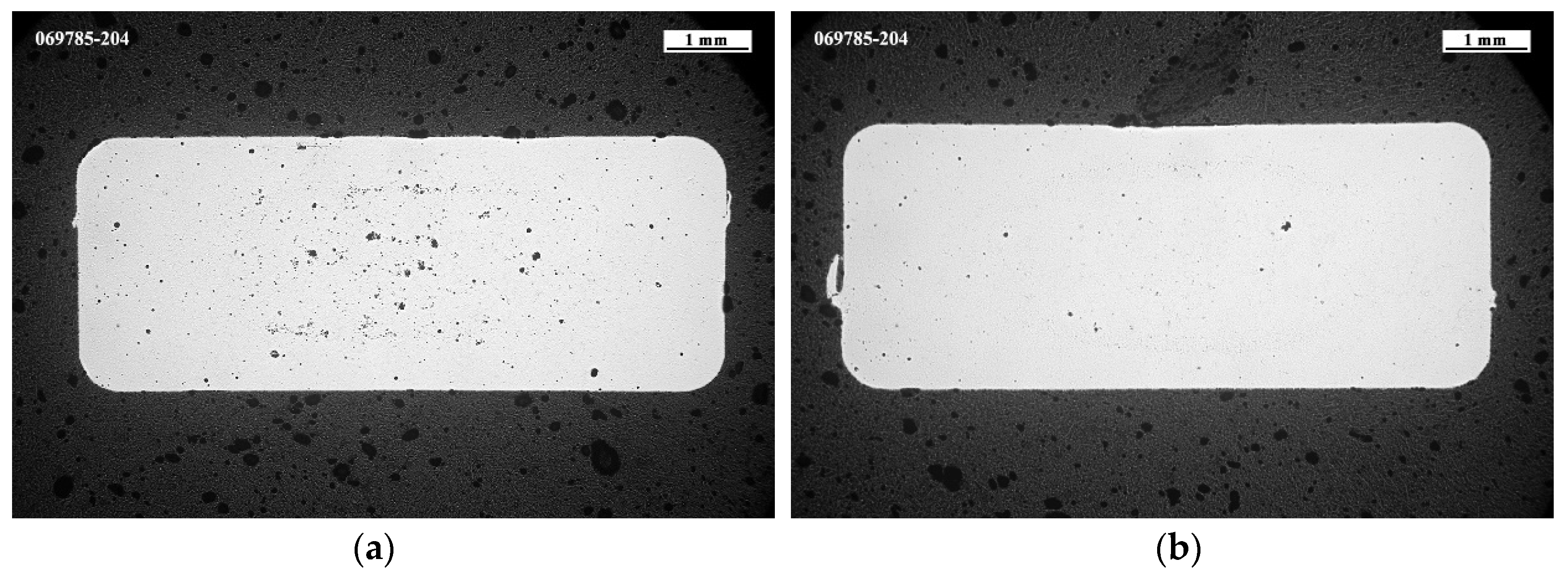
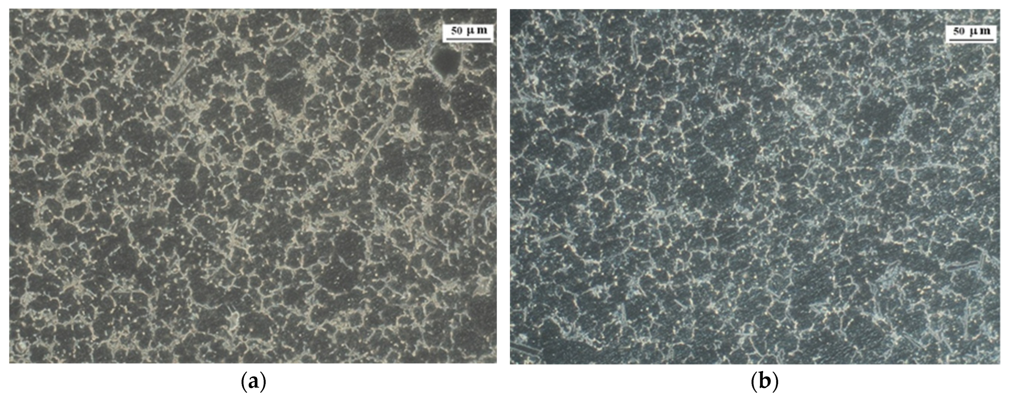
A metallographic characterization was also carried out to study the microstructure of the samples. A section of the central part of one of the tested tensile specimens was cut, polished, and prepared for inspection in a Zeiss optical microscope. The inspection was performed at different magnifications to observe the general cross-section and the microstructural details. Etched samples were prepared with a mixture of hydrofluoric acid and deionized water (1:200) applied for 10–15 s according to ASTM E407 standard [34].
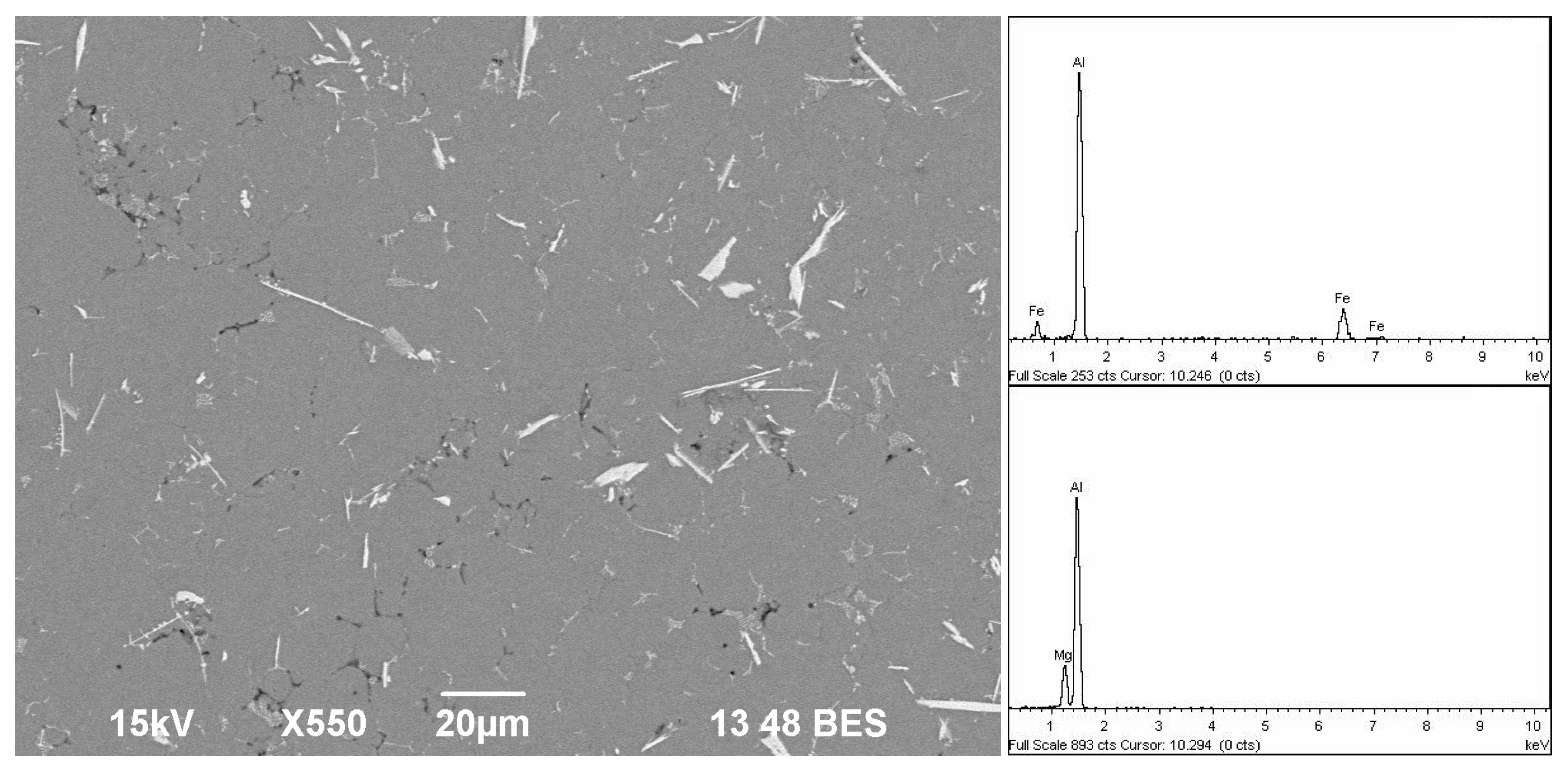
Also, some inspection for phase identification was performed in a scanning electron microscope (SEM) JEOL JSM6940-LV with an Energy Dispersive Spectroscopy (EDS) microprobe OXFORD X-Act (JEOL, Tokyo, Japan).

3. Results and Discussion

3.1. Tensile Properties

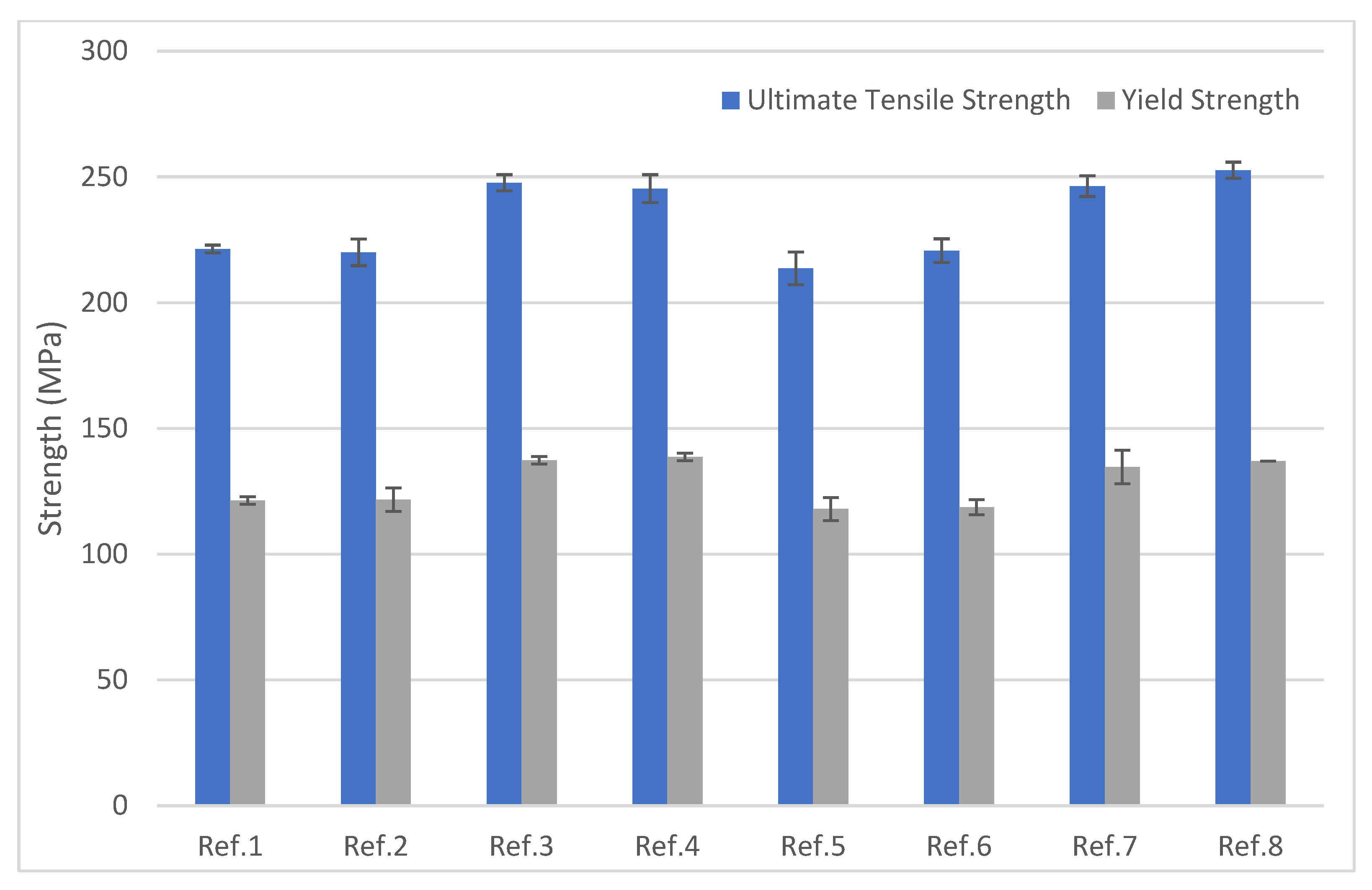
Figure 3 shows the results of engineering ultimate tensile strength (UTS) and yield engineering strength (YS) of the different experiments. It can be observed that experiments applying IP (experiments 3, 4, 7, and 8) consistently exhibit higher average tensile strength and yield strength compared to those without IP (experiments 1, 2, 5, and 6). Average YS values between 134 and 139 MPa and average UTS values between 245 and 253 MPa were reached in all the experiments carried out with the application of IP during the solidification. Conversely, in the experiments in which IP was not applied, the average YS dropped to a range between 118 and 122 MPa, while the UTS was reduced to a range between 213 and 222 MPa. For the other two parameters (vacuum and plunger speed), significant differences in relation to strength results were not observed.
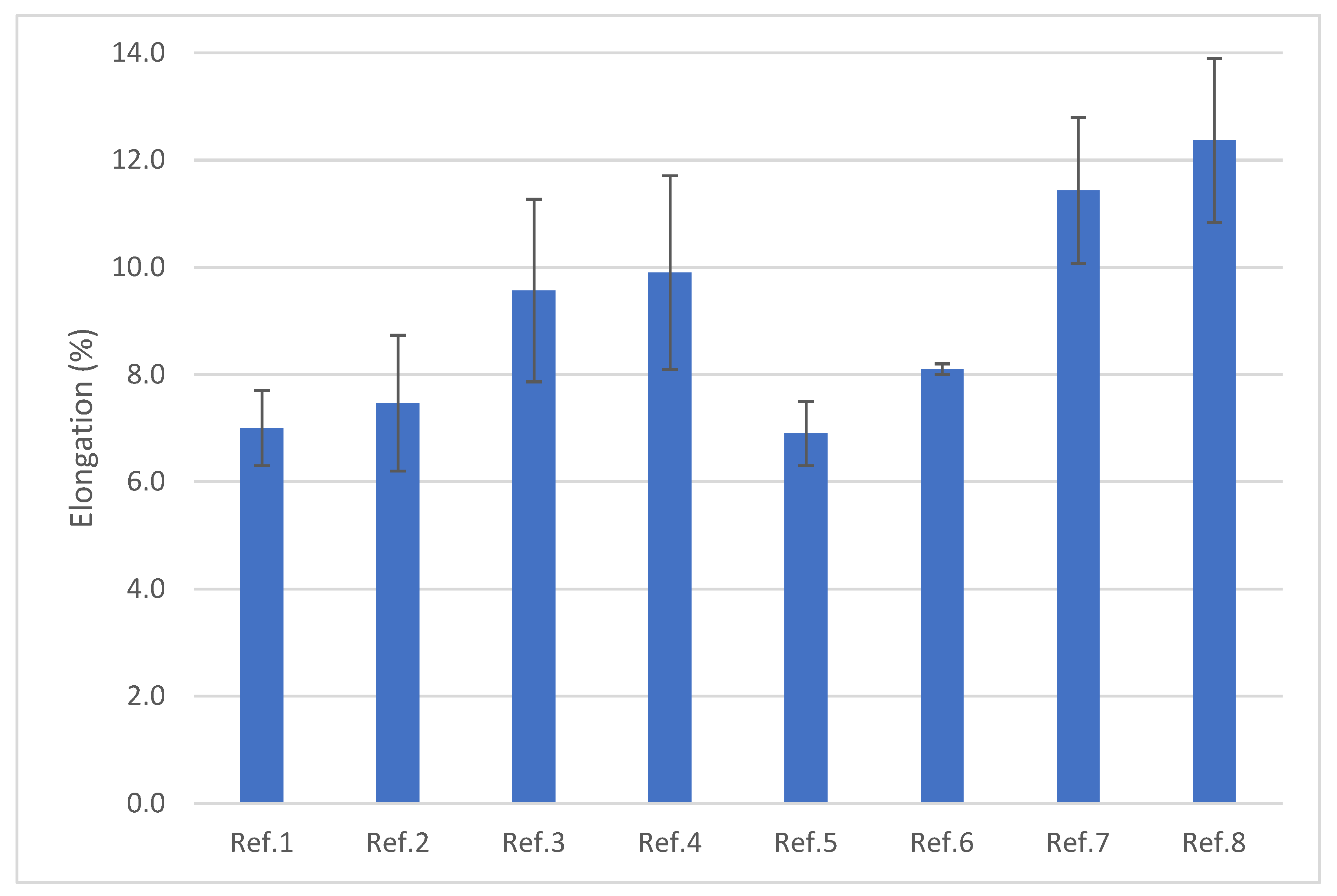
Figure 4 shows the results of the elongation of the different experiments. The castings where IP was applied exhibited higher average elongation values, ranging from 9.5 to 12.5%. In addition, the combined application of vacuum and IP seems to have a positive effect in the increase in the elongation, as evidenced by experiments 7 and 8, which achieved higher average values of elongation than experiments 3 and 4. Moreover, experiments 8 and 4 had slightly higher average elongation values than experiments 7 and 3 respectively, suggesting that plunger speeds of 2.5 m/s could be favorable for achieving enhanced elongation in castings.

3.2. Porosity Results

The porosity of the castings has been studied thanks to the CT analysis conducted on the tensile specimens. Figure 5 shows the volumetric percentage of porosity and the average pore volume for each experiment. It is observed that those experiments with lower porosity and lower average pore volume correspond to the experiments in which IP was applied, which underscores the correlation between reduced porosity levels and superior tensile properties. As explained in the literature, stress tends to concentrate in the vicinity of pores, thereby producing crack initiation [35,36]. A higher pore count or larger pore size increases crack initiation and propagation, thus leading to a quicker fracture and consequently, reduced tensile properties.

3.3. Correlation Between Elongation and Porosity

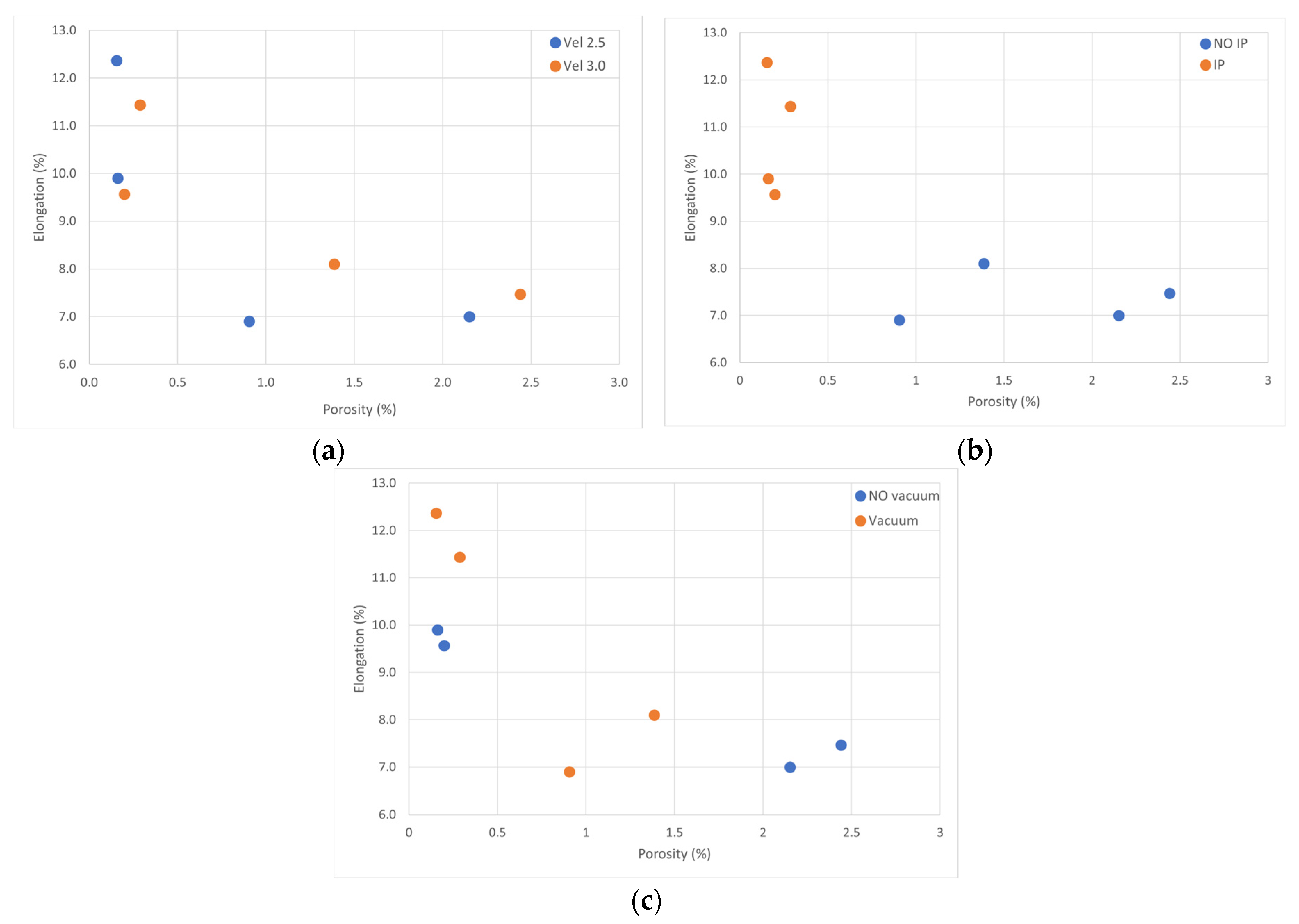
Figure 6 illustrates the relationship between elongation and porosity for each of the variables included in the DoE. It is clearly distinguished that the predominant factor affecting both porosity and elongation is the intensification pressure (Figure 6b). Its application significantly reduces porosity to values below 0.5 vol.% and increases elongation to values above 9.5%.
The Analysis of Variance conducted yielded a p-value of 0.005 for the comparison between porosity and multiplication factor, indicating a significant association at a confidence level greater than 95%. In contrast, the comparison between porosity and vacuum (p = 0.444), and porosity and velocity (p = 0.751), did not show statistically significant relationships.
The efficacy of IP in reducing porosity in aluminum alloy castings has already been reported by some other researchers such as Schaffer and Lauki [23] and Otarawanna [24]. Their studies highlighted that IP values up to 61 MPa significantly reduced porosity in samples produced by HPDC. Wang et al. [37] also showed the correlation between IP increment and reduced casting porosity. The present work reinforces the idea that the pressure applied during the compaction stage of the HPDC process has the potential to compress trapped gases and improve liquid feeding, thus reducing both the average pore volume and the pore count. Consequently, this results in reduced porosity in the samples.
Vacuum application also exhibits the effect of reducing porosity as depicted in Figure 6c. Based on the previous experiences of the authors, this reduction can be attributed to the alleviation of trapped gases during the solidification of the casting. The reduction in porosity becomes more pronounced when IP is not applied, although, in this case, elongation does not appear to be significantly affected. This discrepancy might stem from the notion that the application of vacuum can prevent the formation of the smallest pores but may not have the same effect on bigger pores.

3.4. Computed Tomography

To gain deeper insights into the effects of the application of vacuum on porosity and elongation, CT images of plain tensile specimens of experiments where IP was applied have been studied (Figure 7). Upon examination of these images, it becomes apparent that the concentration of pores in samples assisted by vacuum (experiments 7 and 8) is very similar to those in which vacuum was not applied, under both velocity conditions. It is worth noting that due to the minimum voxel size used in the scanning conditions, these images exclusively reveal pores with volumes exceeding 0.002 mm3. Considering that the application of IP significantly reduces pore volumes, it is reasonable to anticipate the presence of a substantial number of micropores in these samples. In such case, the application of vacuum helps in eliminating these kinds of pores [35], which could explain why samples cast with the assistance of vacuum exhibit higher elongation, even when their porosity percentages are similar (Figure 6c). It can be also appreciated that samples cast in experiments 4 and 8 exhibit slightly lower porosity compared to those cast in experiments 3 and 7, respectively. This could be explained by the fact that when IP is applied, lower velocities favor the removal of pores from the castings before the solidification is completed. This trend can also be appreciated in Figure 6a which shows a slightly lower volumetric percentage of porosity in the samples cast with a plunger speed of 2.5 m/s, compared to those cast at 3.0 m/s. Moreover, this reduction in porosity correlates with higher elongation values. Simulation results have shown that higher velocities are reached at the gate during the filling of the die cavity with higher plunger speeds. This can potentially lead to higher turbulence during the filling process, as already found by some researchers [38]. Even if there is no unanimous consensus on the influence of gate velocity on porosity, Karban tried to synthesize the findings of several scientific studies on this matter and found that most of the works agreed that higher melt velocities in the gate correlated with increased porosity [39]. He also noted that the plunger velocity should ideally fall within the range between 1.7 and 3.4 m/s to minimize porosity. Slower plunger speeds could lead to low gate velocities and premature solidification in the gates, thereby reducing the effective gate area. Conversely, higher plunger speeds lead to high gate velocities causing a higher turbulent flow within the cavity and leading to a higher number of gases trapped after solidification [40]. The higher turbulence at higher plunger speeds could explain the lower porosity observed in the samples cast at 2.5 m/s, especially when IP is not applied.
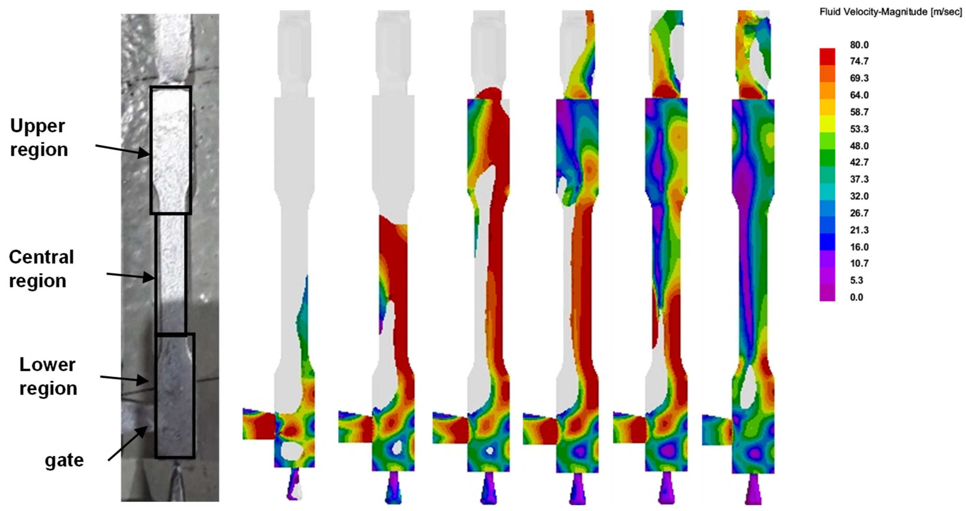
Figure 8 provides a series of frames from the filling simulation with a plunger speed of 2.5 m/s and without the assistance of vacuum, corresponding to experiment 4. The figure visually demonstrates that the highest velocities of the molten aluminum during the filling process are concentrated close to the gate, in the lower section of the specimen, and in the central region. In addition, the last part to solidify can also be found in the lower part of the specimens, so air pockets can be accumulated in this area. This phenomenon offers an explanation for the higher concentration of porosity observed in the lower part of the specimens, as evident in the CT images.

3.5. Metallographic Analysis

As already explained, the presence of pores in castings can result from multiple factors, including both trapped gases, and shrinkage pores produced during solidification. Shrinkage porosity is generally irregular in shape and tends to form clusters between dendritic structures, whereas gas porosity is characterized by rounded and dispersed pores, resulting from trapped air or gases during the filling process. The application of IP proves highly effective in the reduction in shrinkage pores, as it ensures continuous liquid feeding throughout the entire solidification period of the castings. This can be observed when comparing the optical micrographs of samples that have been cast with and without the application of IP. Conversely, the application of vacuum helps evacuate trapped air from the die cavity, thereby significantly reducing the formation of gas pores.
Figure 9 shows optical micrographs of cast samples from experiments 5 and 8, both carried out with the application of vacuum and at the lowest plunger speed, representing the most favorable conditions for the reduction in porosity. In the experiment where IP was applied (image on the right) most of the pores that can be observed correspond to gas pores, likely resulting from dissolved gases in the liquid state and entrapped during solidification. However, the casting in which IP was not applied (image on the left) shows a significant presence of shrinkage porosity alongside visible gas pores. This can be attributed to variances in liquid feeding within these areas, leading to premature solidification before filling these voids. Such issues are avoided when IP is applied, as the additional stroke promotes the introduction of additional liquid aluminum to cover these empty spaces during solidification.
Furthermore, the internal microstructures are very similar in the different samples featuring an Al-rich matrix and needle-like precipitates (Figure 10). Once more, it is evident that shrinkage porosity is present in the sample cast without the application of IP (left), while such pores do not appear when IP is applied (right).
A closer view of these samples using scanning electron microscopy (SEM) reveals some brighter precipitates alongside smaller ones in size and greyer hue in color. The EDS spectra obtained from these precipitates indicate an increase in the iron peaks intensity on the brighter ones (Al13F4 precipitates) and an increase in the magnesium peaks intensity in the greyer hue ones (Al13Mg2 precipitates). SEM analysis was conducted on one sample from each experiment, observing consistent precipitate composition, similar precipitates’ size, and a similar number of precipitates per unit area. As an illustrative example, Figure 11 corresponds to the specimen cast in experiment No8.
To investigate whether variations in mechanical properties might be associated with microstructural features beyond porosity, a sample from each experiment was etched to reveal its internal structure, with a primary focus on grain size (Figure 12). Various micrographs were taken at similar locations near the surface (right side) on the samples to mitigate the impact of skin surface heterogeneity, assuming that the cooling rate would affect their microstructure. The apparent grain size of all samples can be estimated as G = 7 according to ASTM E112 standard [41]. Notably, these results indicate that the microstructure remains largely unchanged independent of the parameters applied in the casting process.

4. Conclusions

The work carried out to optimize the HPDC process parameters for a Si-free NHT alloy has revealed the strong interdependence of the processing conditions, die cavity filling behavior, porosity formation, and resulting mechanical properties. The application of intensification pressure has proven beneficial in reducing porosity, leading to notable enhancements in both tensile strength and elongation. Furthermore, as these alloys do not require heat treatment, the risk of pore growing during post-processing is eliminated.
The combined application of vacuum during die filling and intensification pressure during solidification yield even more favorable elongation results, primarily thanks to the more efficient evacuation of gases through the vacuum valve. Regarding plunger speed, higher velocities are associated with increased porosity, particularly in the upper regions of the tensile specimens, likely caused by turbulent flow and enhanced gas entrapment.
Since aluminum grain size and the nature and content of secondary phases remain largely unaffected by the process parameter variations, the observed improvements in mechanical properties can be attributed primarily to the reduction in porosity.
As a result, for the specific alloy and casting geometry under investigation in this work, the most favorable mechanical properties have been achieved with a plunger speed of 2.5 m/s, combined with vacuum-assisted filling and the application of intensification pressure during solidification. These optimal conditions, identified through a comparative study of different parameters based on a DoE methodology, reveal certain trends that may be considered when defining process parameters for different geometries, albeit needing a dedicated, geometry-specific investigation.

Author Contributions

Conceptualization, A.J. and H.G.; methodology, M.M., A.J., and E.A.; software, E.A. and A.P.; validation, H.G. and N.O.; formal analysis, M.M.; investigation, M.M., A.P., A.J., E.A., and J.C.G.; resources, H.G. and N.O.; data curation, M.M. and J.C.G.; writing—original draft preparation, M.M., A.P., and E.A.; writing—review and editing, A.J., J.C.G., H.G., and N.O.; supervision, H.G. and N.O.; project administration, H.G. and N.O.; funding acquisition, H.G. and N.O. All authors have read and agreed to the published version of the manuscript.

Funding

This work has been partially carried out under the framework of the OASIS European project funded by the European Union through its Horizon2020 framework program under grant agreement No. 814581. It has been also partially supported by the ICME project, funded by the Basque Government under the ELKARTEK Program (KK-2021/00022). It has also received funding from the Basque Government and the European Union under the Complementary Plan “Advanced Materials”, in the framework of the 17th component of the Recovery, Transformation, and Resilience Plan—NEXTGENERATION EU. (EXP. 2022/01367) (A/20220545). This research was also funded by the Department of Economic Development, Sustainability and Environment of the Basque Government for funding the KK-2022/00030 (ANDREA) research project, and the Basque Government group IT 1573-22.

Data Availability Statement

The original contributions presented in the study are included in the article, further inquiries can be directed to the corresponding author.

Conflicts of Interest

The authors declare no conflict of interest.

Abbreviations

The following abbreviations are used in this manuscript:
HPDCHigh Pressure Die Casting
DoEDesing of Experiments
IPIntensification Pressure
NHTNon-Heat Treatable
CTComputed Tomography
NDTNon-Destructive Technique
OEMOriginal Equipment Manufacturer
UTSUltimate Tensile Strength
YSYield Strength

References

  1. Vicario, I.; Egizabal, P.; Galarraga, H.; Plaza, L.M.; Crespo, I. Study of an Al-Si-Cu HPDC Alloy with High Zn Content for the Production of Components Requiring High Ductility and Tensile Properties. Int. J. Mater. Res. 2013, 104, 392–397. [Google Scholar] [CrossRef]
  2. Shaffer, B.; Auffhammer, M.; Samaras, C. Make Electric Vehicles Lighter to Maximize Climate and Safety Benefits. Nature 2021, 598, 254–256. [Google Scholar] [CrossRef] [PubMed]
  3. Fontaras, G.; Zacharof, N.G.; Ciuffo, B. Fuel Consumption and CO2 Emissions from Passenger Cars in Europe—Laboratory versus Real-World Emissions. Prog. Energy Combust. Sci. 2017, 60, 97–131. [Google Scholar] [CrossRef]
  4. Robles Hernandez, F.; Martín Herrera Ramírez, J.; Mackay, R. Al-Si Alloys: Automotive, Aeronautical, and Aerospace Applications; Springer: Berlin/Heidelberg, Germany, 2017. [Google Scholar]
  5. Kaufman, J.G.; Rooy, E. Aluminum Alloy Castings: Properties, Processes and Applications; Asm International: Almere, The Netherlands, 2004; ISBN 0871708035. [Google Scholar]
  6. Hu, R.; Guo, C.; Ma, M. A Study on High Strength, High Plasticity, Non-Heat Treated Die-Cast Aluminum Alloy. Materials 2022, 15, 295. [Google Scholar] [CrossRef] [PubMed]
  7. Vicario, I.; Anza, I.; Sáenz de Tejada, F.; García, J.C.; Galarraga, H.; Merchán, M. Development of New Al-Si9Cu3 Alloys for HPDC Components with Tailored Properties. In Proceedings of the 71st World Foundry Congress: Advanced Sustainable Foundry, WFC 2014, Bilbao, Spain, 19–21 May 2014; World Foundry Organization: Herefordshire, UK, 2014. [Google Scholar]
  8. Alcoa. Alcoa: Non-Heat Treat HPDC Foundry Alloys for Car Body Structures. Spotlightmetal. 2019. Available online: https://castingssa.com/alcoa-non-heat-treat-hpdc-foundry-alloys-for-car-body-structures/ (accessed on 12 September 2025).
  9. Wiesner, S.; Saka, Y. Characteristics of New Alloys for HPDC Structural Parts. Spotlightmetal. 2019. Available online: https://www.scribd.com/document/675046149/spotlightmetal-characteristics-of-new-alloys-for-hpdc-structural-parts-882428 (accessed on 12 September 2025).
  10. Casarotto, F.; Franke, A.J.; Franke, R. High-Pressure Die-Cast (HPDC) Aluminum Alloys for Automotive Applications. In Advanced Materials in Automotive Engineering; Elsevier: Amsterdam, The Netherlands, 2012; pp. 109–149. [Google Scholar]
  11. Cho, J.-S.; Kim, J.-H.; Sim, W.-J.; Im, H.-J. The Influence of Alloying Elements on the Fluidity of Al-Zn-Mg Alloys. J. Korea Foundry Soc. 2012, 32, 127–132. [Google Scholar] [CrossRef]
  12. Soares, G.; Neto, R.; Madureira, R.; Soares, R.; Silva, J.; Silva, R.P.; Araújo, L. Characterization of Al Alloys Injected through Vacuum-Assisted HPDC and Influence of T6 Heat Treatment. Metals 2023, 13, 389. [Google Scholar] [CrossRef]
  13. Vivas, J.; Fernández-Calvo, A.I.; Aldanondo, E.; Irastorza, U.; Álvarez, P. Friction Stir Weldability at High Welding Speed of Two Structural High Pressure Die Casting Aluminum Alloys. J. Manuf. Mater. Process. 2022, 6, 160. [Google Scholar] [CrossRef]
  14. Zhang, Y.; Lordan, E.; Dou, K.; Wang, S.; Fan, Z. Influence of Porosity Characteristics on the Variability in Mechanical Properties of High Pressure Die Casting (HPDC) AlSi7MgMn Alloys. J. Manuf. Process 2020, 56, 500–509. [Google Scholar] [CrossRef]
  15. Dou, K.; Lordan, E.; Zhang, Y.; Jacot, A.; Fan, Z. A Novel Approach to Optimize Mechanical Properties for Aluminum Alloy in High Pressure Die Casting (HPDC) Process Combining Experiment and Modelling. J. Mater. Process Technol. 2021, 296, 117193. [Google Scholar] [CrossRef]
  16. Zhang, Y.; Shen, F.; Zheng, J.; Münstermann, S.; Li, T.; Han, W.; Huang, S. Ductility Prediction of HPDC Aluminum Alloy Using a Probabilistic Ductile Fracture Model. Theor. Appl. Fract. Mech. 2022, 119, 103381. [Google Scholar] [CrossRef]
  17. Adamane, A.R.; Arnberg, L.; Fiorese, E.; Timelli, G.; Bonollo, F. Influence of Injection Parameters on the Porosity and Tensile Properties of High-Pressure Die Cast Al-Si Alloys: A Review. Int. J. Met. 2015, 9, 43–53. [Google Scholar] [CrossRef]
  18. Wilczek, A.; Długosz, P.; Hebda, M. Porosity Characterization of Aluminum Castings by Using Particular Non-Destructive Techniques. J. Nondestruct. Eval. 2015, 34, 26. [Google Scholar] [CrossRef]
  19. Li, Z.; Jing, Y.; Guo, H.; Sun, X.; Yu, K.; Yu, A.; Jiang, X.; Yang, X.J. Study of 3D Pores and Its Relationship with Crack Initiation Factors of Aluminum Alloy Die Castings. Metall. Mater. Trans. B Process Metall. Mater. Process. Sci. 2019, 50, 1204–1212. [Google Scholar] [CrossRef]
  20. Lordan, E.; Lazaro-Nebreda, J.; Zhang, Y.; Dou, K.; Blake, P.; Fan, Z. On the Relationship between Internal Porosity and the Tensile Ductility of Aluminum Alloy Die-Castings. Mater. Sci. Eng. A 2020, 778, 139107. [Google Scholar] [CrossRef]
  21. Yu, W.; Yuan, Z.; Guo, Z.; Xiong, S. Characterization of A390 Aluminum Alloy Produced at Different Slow Shot Speeds Using Vacuum Assisted High Pressure Die Casting. Trans. Nonferrous Met. Soc. China 2017, 27, 2529–2538. [Google Scholar] [CrossRef]
  22. Brown, J.R. Foseco Non-Ferrous Foundryman’s Handbook; Butterworth-Heinemann: Oxford, UK, 2016. [Google Scholar]
  23. Schaffer, P.L.; Laukli, H.I. Recent Developments in Aluminum High Pressure Die Castings. Die Cast. Eng. 2012, 56, 20–22. [Google Scholar]
  24. Otarawanna, S.; Laukli, H.I.; Gourlay, C.M.; Dahle, A.K. Feeding Mechanisms in High-Pressure Die Castings. Metall. Mater. Trans. A 2010, 41, 1836–1846. [Google Scholar] [CrossRef]
  25. Watanabe, I.; Watkins, J.H.; Nakajima, H.; Atsuta, M.; Okabe, T. Effect of Pressure Difference on the Quality of Titanium Casting. J. Dent. Res. 1997, 76, 773–779. [Google Scholar] [CrossRef]
  26. Li, X.; Xiong, S.M.; Guo, Z. Correlation between Porosity and Fracture Mechanism in High Pressure Die Casting of AM60B Alloy. J. Mater. Sci. Technol. 2016, 32, 54–61. [Google Scholar] [CrossRef]
  27. dos Santos, S.L.; Antunes, R.A.; Santos, S.F. Influence of Injection Temperature and Pressure on the Microstructure, Mechanical and Corrosion Properties of a AlSiCu Alloy Processed by HPDC. Mater. Des. 2015, 88, 1071–1081. [Google Scholar] [CrossRef]
  28. Rheinfelden Alloys. HPDC Alloys for Structural Casts in Vehicle Construction; Rheinfelden Alloys: Rheinfelden, Germany, 2017. [Google Scholar]
  29. Herman, E.A. (NADCA) Die Casting Process Control; North America Die Casting Association: Arlington Heights, IL, USA, 2003. [Google Scholar]
  30. Anglada, E.; Meléndez, A.; Vicario, I.; Arratibel, E.; Aguillo, I. Adjustment of a High Pressure Die Casting Simulation Model Against Experimental Data. Procedia Eng. 2015, 132, 966–973. [Google Scholar] [CrossRef]
  31. Anglada, E.; Meléndez, A.; Vicario, I.; Idoiaga, J.K.; Mugarza, A.; Arratibel, E. Prediction and Validation of Shape Distortions in the Simulation of High Pressure Die Casting. J. Manuf. Process 2018, 33, 228–237. [Google Scholar] [CrossRef]
  32. Anglada, E.; Boto, F.; De Cortazar, M.G.; Garmendia, I. Metamodels’ Development for High Pressure Die Casting of Aluminum Alloy. Metals 2021, 11, 1747. [Google Scholar] [CrossRef]
  33. UNE-EN ISO 6892-1; Metallic Materials—Tensile Testing—Part 1: Method of Test at Room Temperature. AENOR International, S.A.U: Madrid, Spain, 2020.
  34. ASTM E407; Standard Practice for Microetching Metals and Alloys. ASTM International: West Conshohocken, PA, USA, 2007.
  35. Cao, H.; Luo, Z.; Wang, C.; Wang, J.; Hu, T.; Xiao, L.; Che, J. The Stress Concentration Mechanism of Pores Affecting the Tensile Properties in Vacuum Die Casting Metals. Materials 2020, 13, 3019. [Google Scholar] [CrossRef] [PubMed]
  36. Dong, X.; Zhu, X.; Ji, S. Effect of Super Vacuum Assisted High Pressure Die Casting on the Repeatability of Mechanical Properties of Al-Si-Mg-Mn Die-Cast Alloys. J. Mater. Process Technol. 2019, 266, 105–113. [Google Scholar] [CrossRef]
  37. Wang, C.; Yao, J.; Zhao, H.; Yang, R. Influence of Intensification Pressures on Pores in Die-Cast ADC12 Alloys. China Foundry 2019, 16, 184–189. [Google Scholar] [CrossRef]
  38. Cao, H.; Shen, C.; Wang, C.; Xu, H.; Zhu, J. Direct Observation of Filling Process and Porosity Prediction in High Pressure Die Casting. Materials 2019, 12, 1099. [Google Scholar] [CrossRef]
  39. Karban, R., Jr. The Effects of Intensification Pressure, Gate Velocity, and Intermediate Shot Velocity on the Internal Quality of Aluminum Die Castings. Ph.D. Thesis, Purdue University, West Lafayette, IN, USA, 2000. [Google Scholar]
  40. Dou, K.; Lordan, E.; Zhang, Y.J.; Jacot, A.; Fan, Z.Y. Numerical Simulation of Fluid Flow, Solidification and Defects in High Pressure Die Casting (HPDC) Process. IOP Conf. Ser. Mater. Sci. Eng. 2019, 529, 012058. [Google Scholar] [CrossRef]
  41. ASTM E112; Standard Test Methods for Determining Average Grain Size. ASTM International: West Conshohocken, PA, USA, 2024.
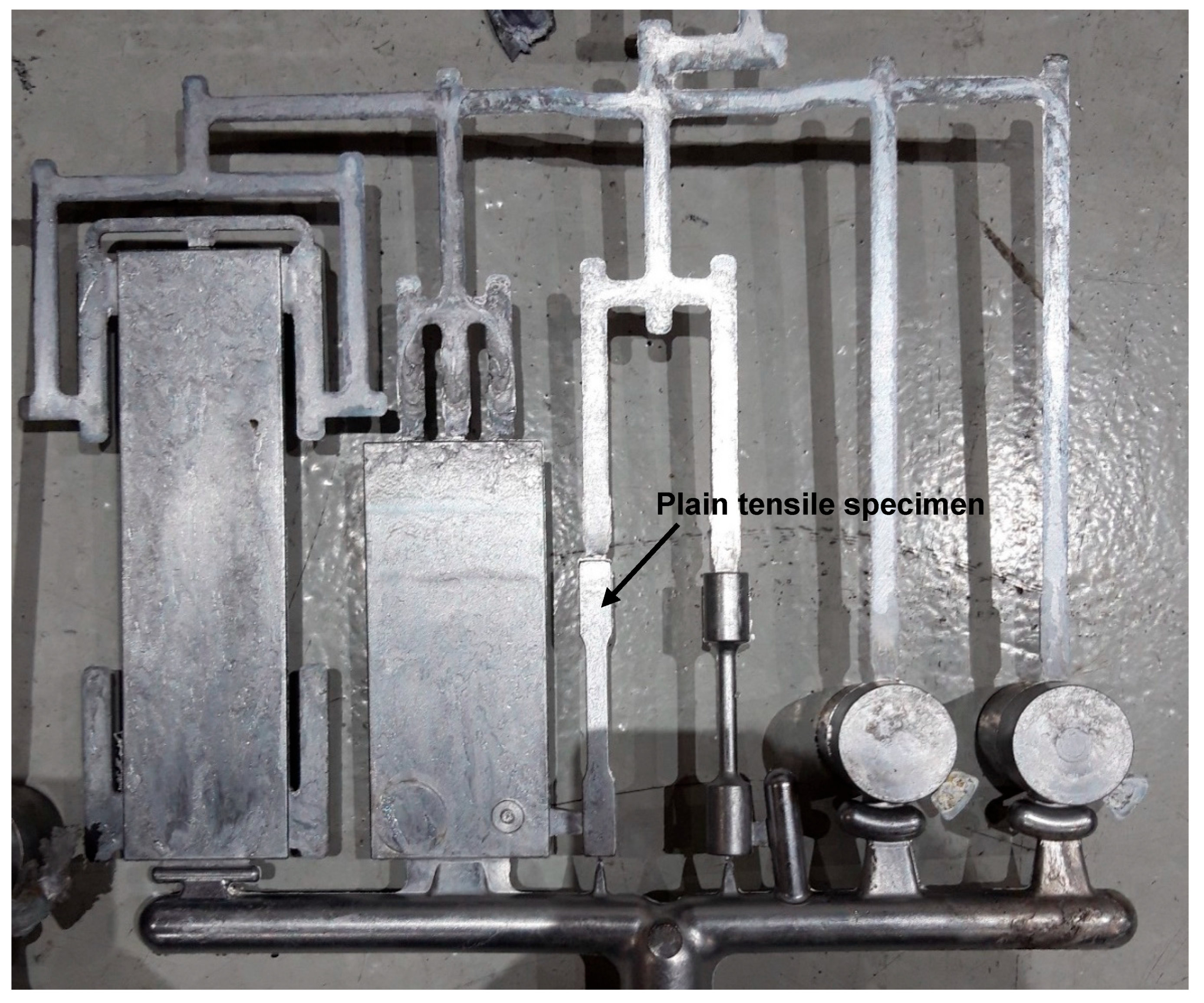
Figure 1. Aluminum casting containing the plain tensile specimen.
Metals 15 01071 g001
Figure 2. Set up into Computed Tomography (CT) machine.
Metals 15 01071 g002
Figure 3. Engineering Ultimate Tensile Strength (UTS) and Yield Strength (YS) of the different experiments.
Metals 15 01071 g003
Figure 4. Elongation values of the different experiments.
Metals 15 01071 g004
Figure 5. Percentage of porosity and average pore volume of the different experiments.
Metals 15 01071 g005
Figure 6. Correlation between elongation and porosity at different conditions: (a) different plunger velocities, (b) application of IP, and (c) application of vacuum.
Metals 15 01071 g006
Figure 7. CT images of plain tensile specimens from experiments 3, 4, 7, and 8.
Metals 15 01071 g007
Figure 8. Filling simulation of the tensile specimen for experiment 4.
Metals 15 01071 g008
Figure 9. Optical micrographs of samples cast under vacuum and 2.5 m/s and (a) without the application of IP and (b) with the application of IP.
Metals 15 01071 g009
Figure 10. Optical micrographs at ×200 magnifications of samples cast under vacuum and 2.5 m/s and (a) without the application of IP and (b) with the application of IP.
Metals 15 01071 g010
Figure 11. Precipitates observed in the samples (left image). The needle-like bigger and brighter ones are richer in iron (upper right spectrum); the smaller and greyer hue are richer in magnesium (bottom right spectrum).
Metals 15 01071 g011
Figure 12. Representative area of etched samples (×200) showing grain boundaries for the samples cast under vacuum and 2.5 m/s and (a) without the application of IP and (b) with the application of IP.
Metals 15 01071 g012
Table 1. Set of experiments defined by the DoE.
Experiment Ref.VacuumIntensification PressurePlunger Speed (m/s)
1NoNo2.5
2NoNo3.0
3NoYes3.0
4NoYes2.5
5YesNo2.5
6YesNo3.0
7YesYes3.0
8YesYes2.5
Table 2. Chemical composition of the Castaduct®-42 in the ingot (% of mass).
ElementSiFeCuMnMgZnTi
Wt.%0.291.710.0440.0354.880.0700.034
Table 3. Scanning conditions by CT.
Focal Spot Size (mm)Hardware FiltersVoltage (kV)Current (mA)Exposure Time (ms)ProjectionsVoxel Size (µm)
0.41 mm Cu & 0.5 mm Sn1504100144091
Disclaimer/Publisher’s Note: The statements, opinions and data contained in all publications are solely those of the individual author(s) and contributor(s) and not of MDPI and/or the editor(s). MDPI and/or the editor(s) disclaim responsibility for any injury to people or property resulting from any ideas, methods, instructions or products referred to in the content.