Low-Alloyed Spring Steel: Nanostructure and Strength After Austempering
Abstract
1. Introduction
2. Materials and Methods
3. Results
4. Discussion
5. Conclusions
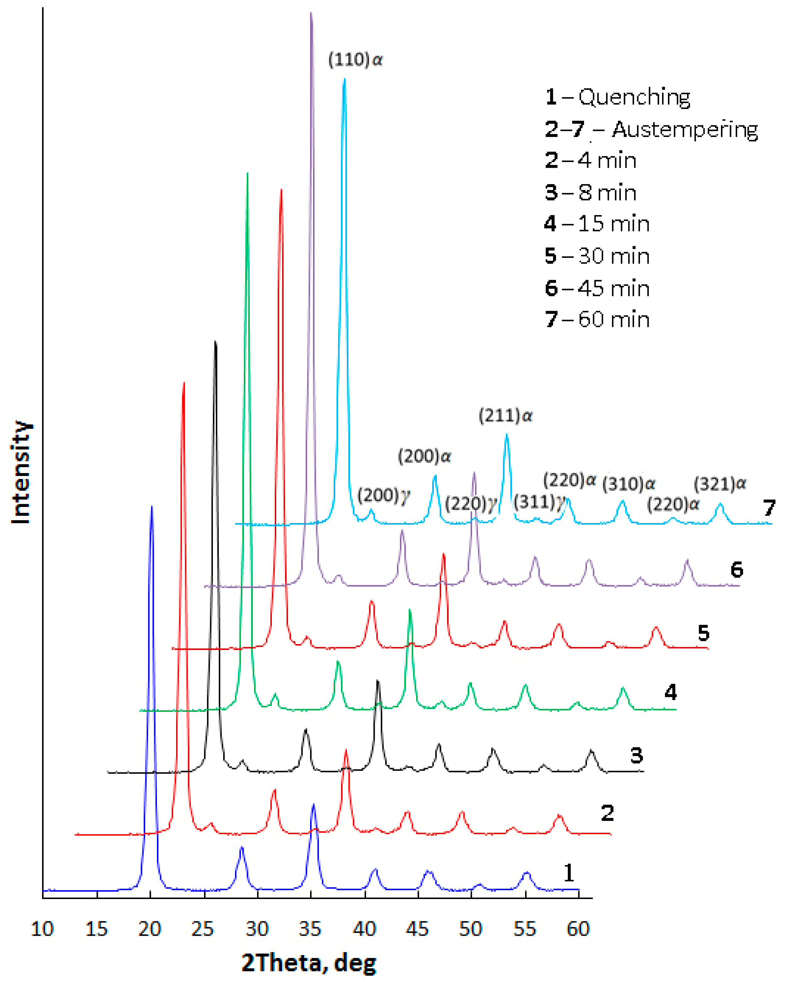
- The minimal content of alloying elements provides the possibility to obtain a nanobainite microstructure in 60Si2 steel at a low temperature of austempering during a relatively short time. This time is comparable to the generally accepted time for heat treatment of steel parts, such as that for tempering. XRD investigations demonstrated that the incubation period for bainitic transformation in 60Si2 steel at 250 °C is less than 4 min.
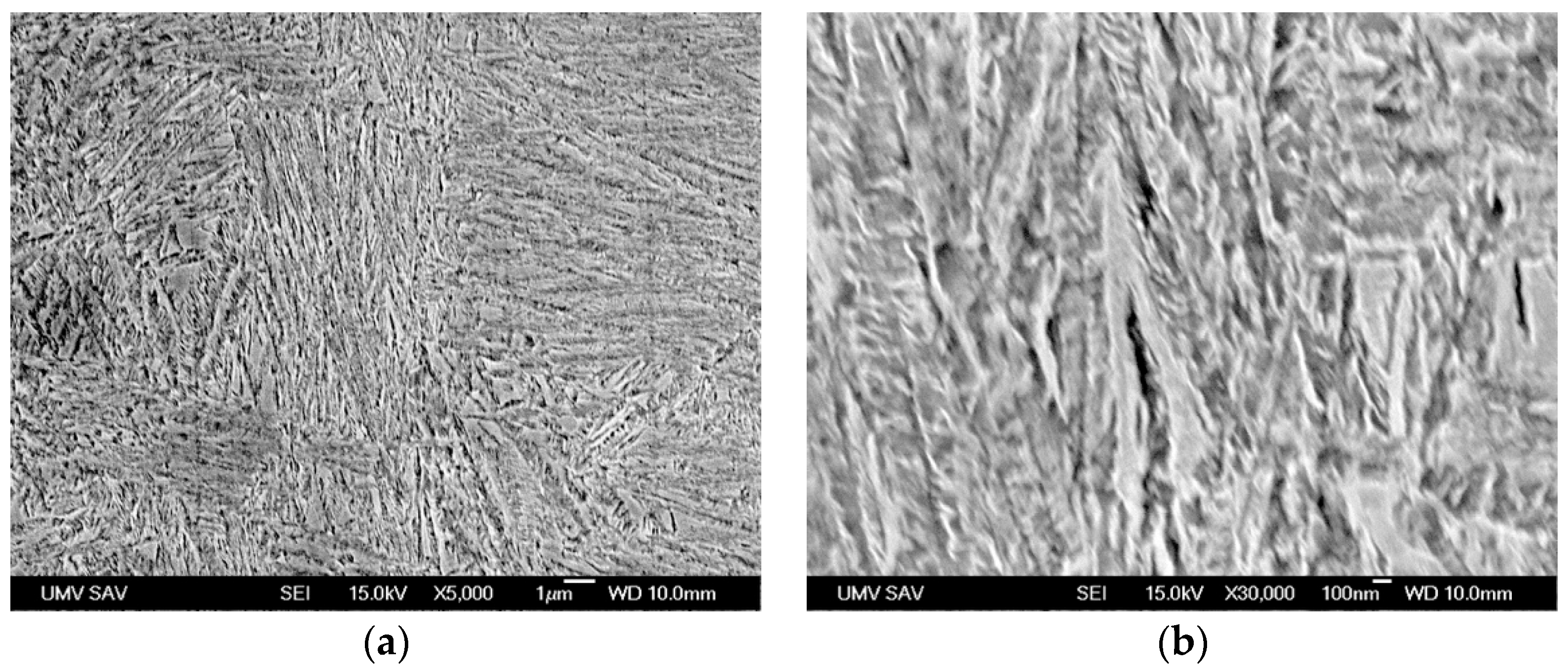
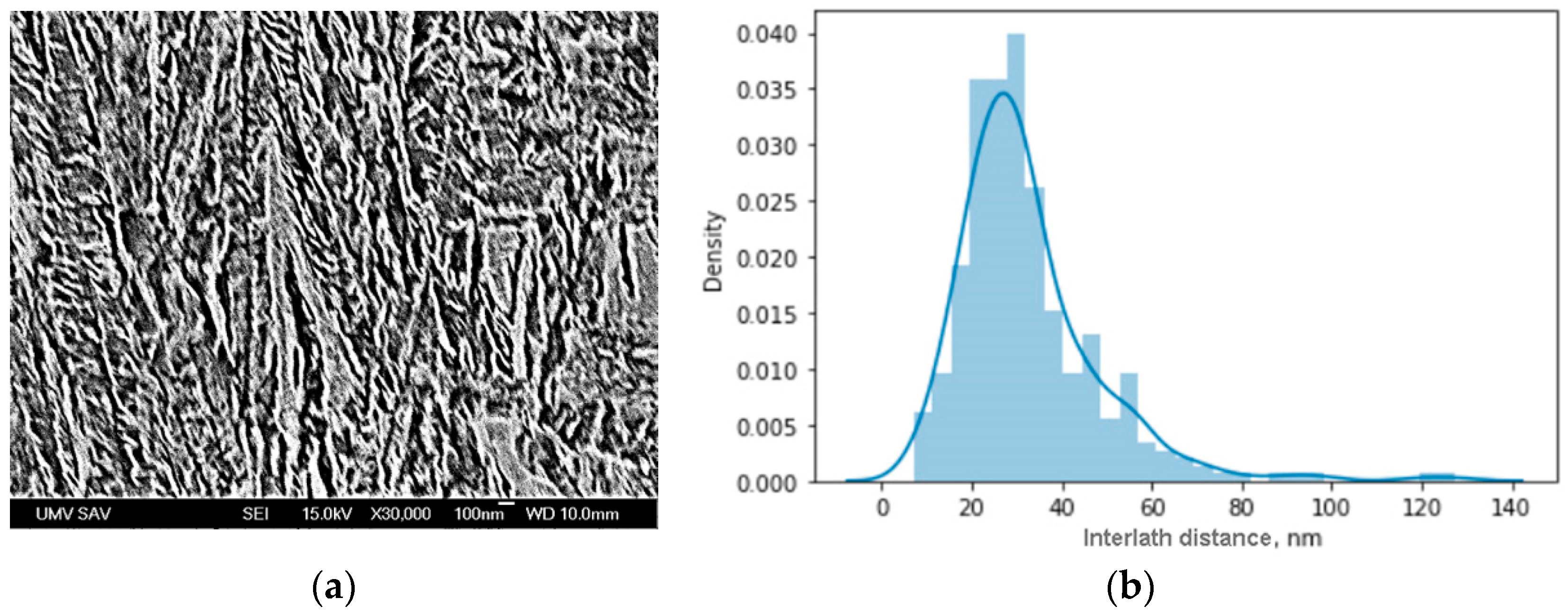
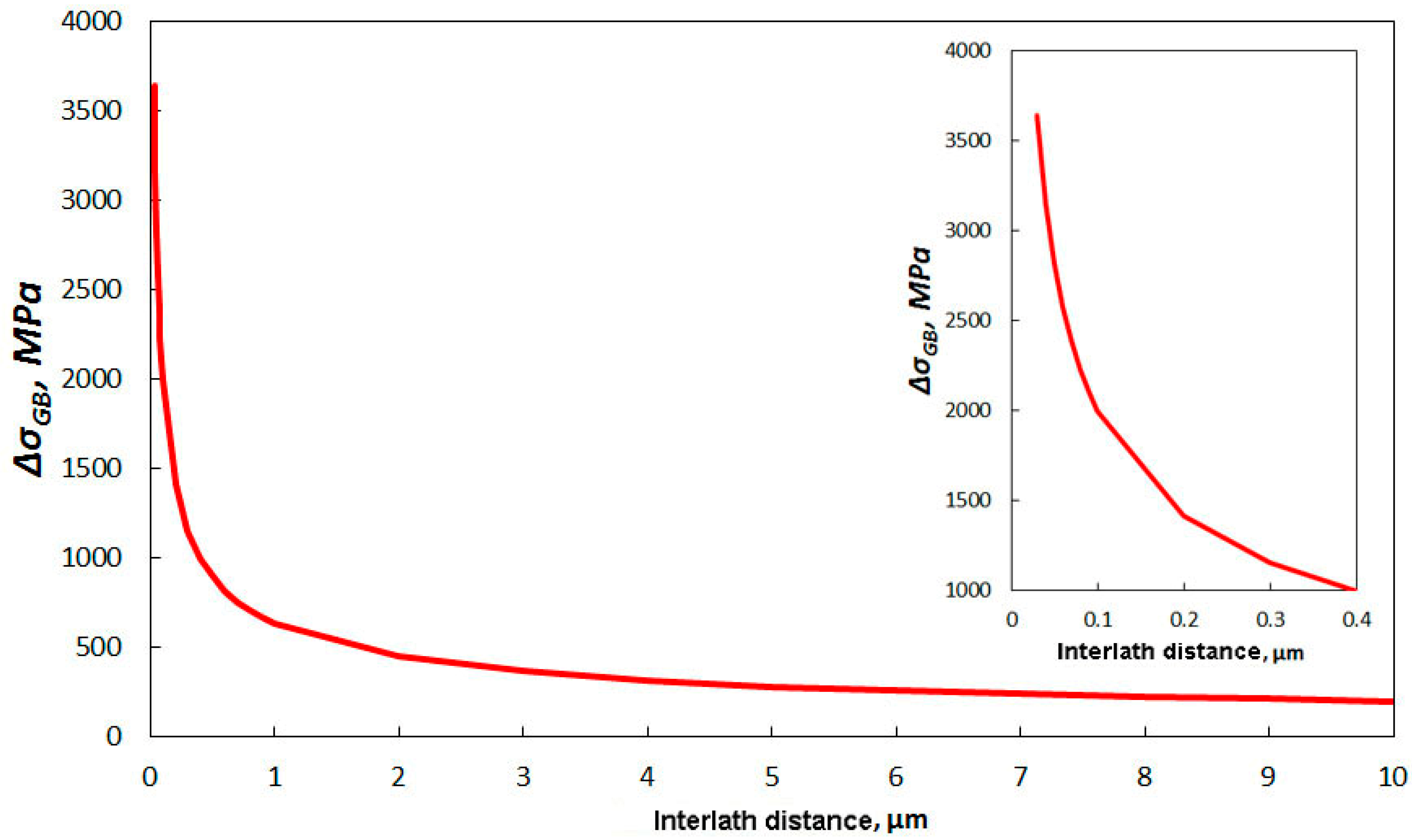
- The distribution of distances between phase borders in bainite indicate that the mode value is 30 nm. According to the Hall–Petch law, such a nanoscale interlath distance provides yield strength at the gigapascal level.
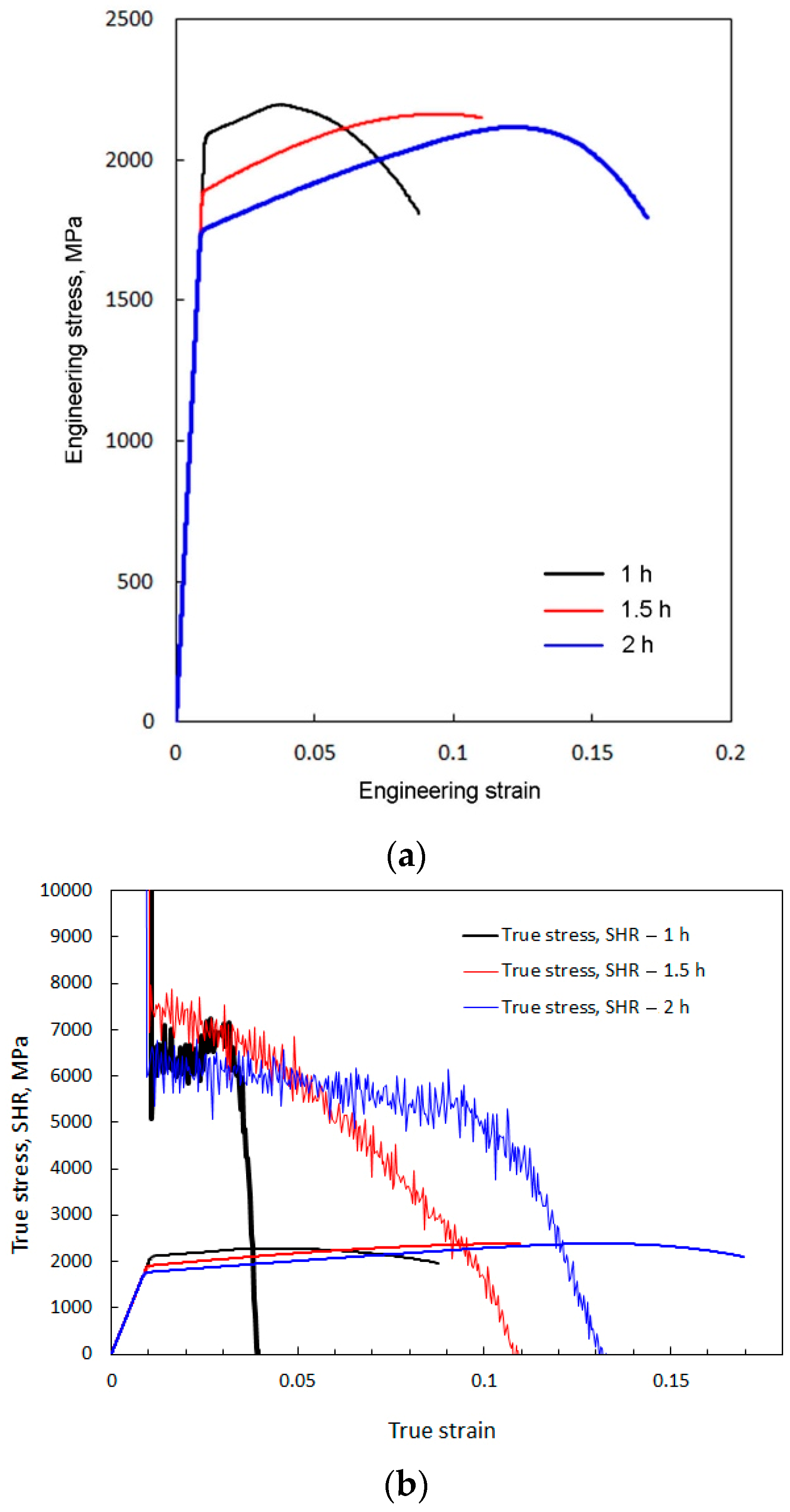
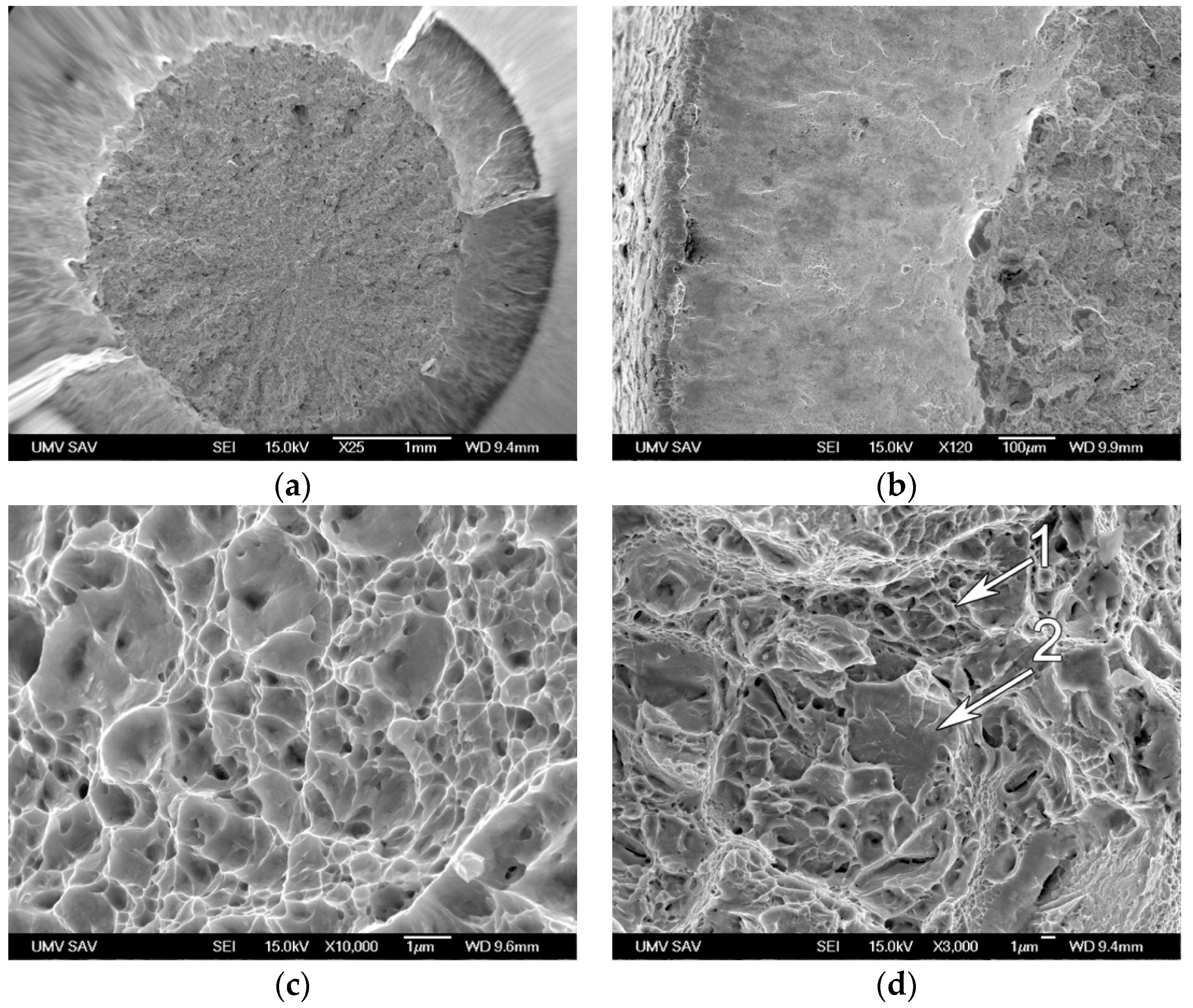
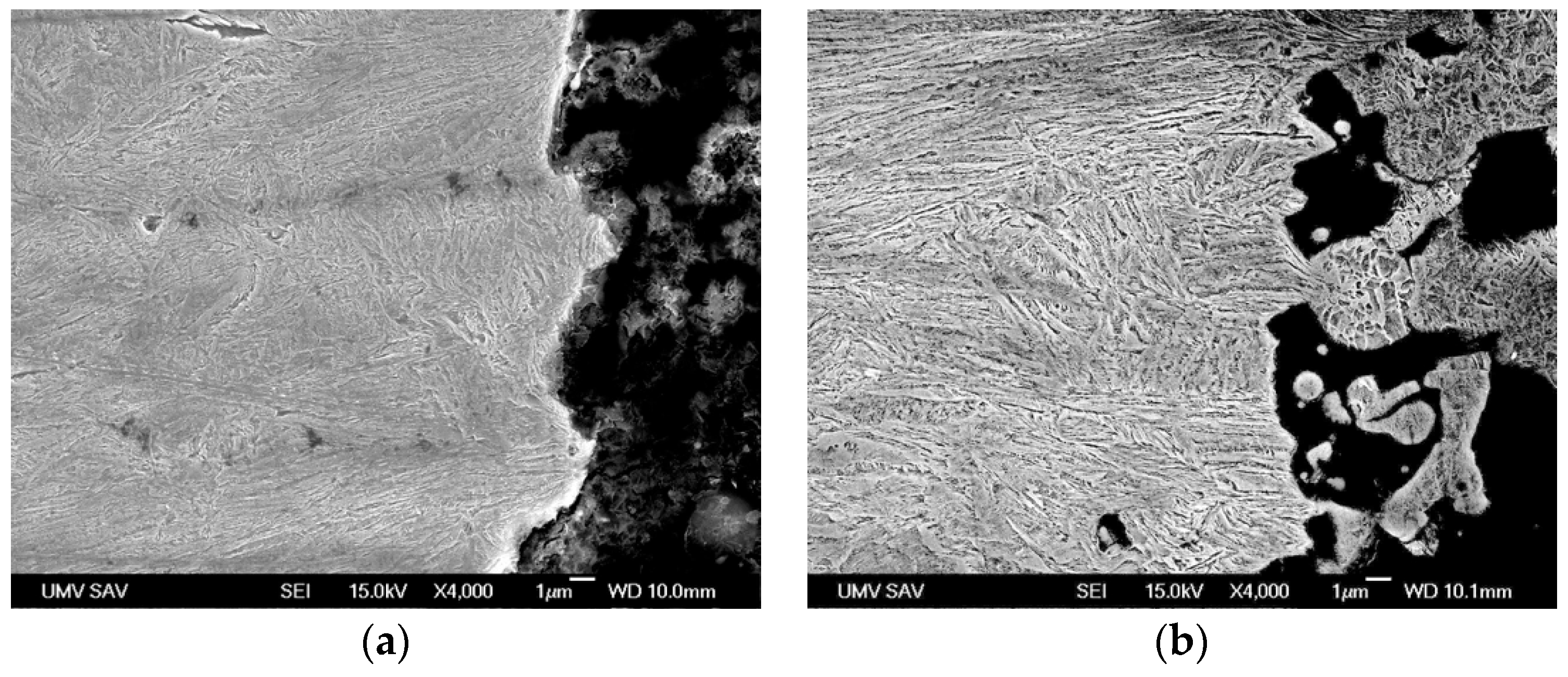
- Along with the high strength obtained, an acceptable level of ductility was also achieved. Analysis of the fracture surface and microstructures of the longitudinal cross-section of the broken sample confirmed the ductile mode of fracture.
- Further research should focus on optimizing the composition and processing routes of spring steels for use as high-strength materials in safety-critical structural applications.
Author Contributions
Funding
Data Availability Statement
Conflicts of Interest
References
- Kumar, D.P.; Amit, S.; Chand, M.S.R. Influence of various nano-size materials on fresh and hardened state of fast setting high early strength concrete [FSHESC]: A state-of-the-art review. Constr. Build. Mater. 2021, 277, 122299. [Google Scholar]
- Salma, U.; Hasanuzzaman, M.; Bhuiyan, I.U.; Hashmi, S. High Strength Alumina Composite for Protective Armors: A Review. Compr. Mater. Process. 2024, 12, 67–78. [Google Scholar]
- Fan, Q.; Duan, H.; Xing, X. A review of composite materials for enhancing support, flexibility and strength in exercise. Alex. Eng. J. 2024, 94, 90–103. [Google Scholar] [CrossRef]
- Qu, R.; Liu, Z.; Wang, R.; Zhang, Z. Yield strength and yield strain of metallic glasses and their correlations with glass transition temperature. J. Alloy. Compd. 2015, 637, 44–54. [Google Scholar] [CrossRef]
- Egami, T.; Iwashita, T.; Dmowski, W. Mechanical Properties of Metallic Glasses. Metals 2013, 3, 77–113. [Google Scholar] [CrossRef]
- Li, Y.; Choi, P.; Goto, S.; Borchers, C.; Raabe, D.; Kirchheim, R. Evolution of strength and microstructure during annealing of heavily cold-drawn 6.3 GPa hypereutectoid pearlitic steel wire. Acta Mater. 2012, 60, 4005–4016. [Google Scholar] [CrossRef]
- Raabe, D.; Choi, P.-P.; Li, Y.; Kostka, A.; Sauvage, X.; Lecouturier, F.; Hono, K.; Kirchheim, R.; Pippan, R.; Embury, D. Metallic composites processed via extreme deformation: Toward the limits of strength in bulk materials. MRS Bull. 2010, 35, 982–991. [Google Scholar] [CrossRef]
- Li, Y.; Choi, P.; Borchers, C.; Westerkamp, S.; Goto, S.; Raabe, D.; Kirchheim, R. Atomic-scale mechanisms of deformation-induced cementite decomposition in pearlite. Acta Mater. 2011, 59, 3965–3977. [Google Scholar] [CrossRef]
- Borchers, C.; Al-Kassab, T.; Goto, S.; Kirchheim, R. Partially amorphous nanocomposite obtained from heavily deformed pearlitic steel. Mater. Sci. Eng. A 2009, 502, 131–138. [Google Scholar] [CrossRef]
- Lesch, C.; Kwiaton, N.; Klose, F.B. Advanced High Strength Steels (AHSS) for Automotive Applications—Tailored Properties by Smart Microstructural Adjustments. Steel Res. Int. 2017, 88. [Google Scholar] [CrossRef]
- Lee, K.Y. Tensile properties of different chemical compositions for TRIP-assisted multiphase steel for automobile structures. Int. J. Automot. Technol. 2008, 9, 87–93. [Google Scholar] [CrossRef]
- Xu, D.; Li, J.; Meng, Q.; Liu, Y.; Li, P. Effect of heating rate on microstructure and mechanical properties of TRIP-aided multiphase steel. J. Alloy. Compd. 2014, 614, 94–101. [Google Scholar] [CrossRef]
- Xiong, Z.-P.; Ren, X.-P.; Bao, W.-P.; Li, S.-X.; Qu, H.-T. Dynamic mechanical properties of the Fe–30Mn–3Si–4Al TWIP steel after different heat treatments. Mater. Sci. Eng. A 2011, 530, 426–431. [Google Scholar] [CrossRef]
- Yan, J.; Zhang, X.; Liu, H.; Miyamoto, G.; Cao, Z.; Zhang, Y.; Pei, Y.; Shi, P.; Chen, J.; Furuhara, T. Enhancing ductility of the TRIP aided bainitic ferrite steel by Mn heterogeneity introduced via reversion: Towards the 3rd generation. Scr. Mater. 2024, 252, 116241. [Google Scholar] [CrossRef]
- Pelligra, C.; Amirkhiz, B.S.; Zafer, N.; Kang, J.; Wilkinson, D.S. Microstrain partitioning, transformation induced plasticity, and damage evolution of a third generation medium Mn advanced high strength steel. Mater. Sci. Eng. A 2024, 919, 147447. [Google Scholar] [CrossRef]
- Zurnadzhy, V.I.; Efremenko, V.G.; Brykov, M.N.; Petryshynets, I.; Pastukhova, T.V.; Kussa, R.A. The Metastability of Retained Austenite in Multiphase Steel during Abrasive Wear. J. Frict. Wear 2020, 41, 119–124. [Google Scholar] [CrossRef]
- Avila, D.d.S.; van Bohemen, S.M.; Huizenga, R.M.; Offerman, S.E.; Santofimia, M.J. Shortening the heat treatment of third generation advanced high strength steels by forming carbide free bainite in the presence of martensite. Mater. Sci. Eng. A 2025, 931, 148241. [Google Scholar] [CrossRef]
- Huang, M.; He, B.; Li, Y.; Wang, M. TRIP-Assisted Multiphase Steel. In High Strength Steels; Elsevier: Amsterdam, The Netherlands, 2025; pp. 95–136. [Google Scholar]
- Yao, S.; Cao, K.; Wang, D.; Chen, J.; Zhao, A. Effect of Intermediate Annealing Before Cold Rolling on Microstructure and Mechanical Properties of Medium Manganese Steel and Mechanism of Phase Transformation Plasticity. Metals 2025, 15, 500. [Google Scholar] [CrossRef]
- Hesse, O.; Liefeith, J.; Kunert, M.; Kapustyan, A.; Brykov, M.; Efremenko, V. Bainite in steels with high resistance against abrasive wear. Tribol. Und Schmier. 2016, 63, 5–13. [Google Scholar]
- Brykov, M.N.; Akrytova, T.O.; Osipov, M.J.; Petryshynets, I.; Puchy, V.; Efremenko, V.G.; Shimizu, K.; Kunert, M.; Hesse, O. Abrasive Wear of High-Carbon Low-Alloyed Austenite Steel: Microhardness, Microstructure and X-ray Characteristics of Worn Surface. Materials 2021, 14, 6159. [Google Scholar] [CrossRef]
- Koval’, A.D.; Efremenko, V.G.; Brykov, M.N.; Andrushchenko, M.I.; Kulikovskii, R.A.; Efremenko, A.V. Principles for developing grinding media with increased wear resistance. Part 1. Abrasive wear resistance of iron-based alloys. J. Frict. Wear 2012, 33, 39–46. [Google Scholar] [CrossRef]
- Hesse, O.; Merker, J.; Brykov, M.; Efremenko, V. On the strength of low-alloy steels with increased carbon content against abrasive wear. Tribol. Schmier. 2013, 60, 37–43. [Google Scholar]
- Zurnadzhy, V.; Efremenko, V.; Petryshynets, I.; Dabalà, M.; Franceschi, M.; Wu, K.; Kováč, F.; Chabak, Y.; Puchy, V.; Brykov, M. Alternative Approach for the Intercritical Annealing of (Cr, Mo, V)-Alloyed TRIP-Assisted Steel before Austempering. Metals 2022, 12, 1814. [Google Scholar] [CrossRef]
- Wang, J.; El-Fallah, G.; Chang, X.; Peng, Y.; Tao, Q. Achieving 2.7 GPa tensile strength in ultrastrong high-carbon steel through prolonged low-temperature tempering. Mater. Charact. 2024, 215. [Google Scholar] [CrossRef]
- Li, Y.; Wang, E.; Zhang, L.; Zhao, X.; Gao, R.; Zhu, W. Ultra-high strength and high ductility 60Si2CrVNb spring steel with multiphase microstructure controlled by austempering. J. Mater. Res. Technol. 2024, 30, 5855–5868. [Google Scholar] [CrossRef]
- Li, G.; Long, W.; Yu, X.; Wu, G.; Chen, W.; Jiang, Q.; Zhang, C.; Wu, H.; Gao, J.; Zhao, H.; et al. Hot deformation behavior and microstructural evolution of high-carbon high-strength low alloy steel. J. Mater. Res. Technol. 2024, 33, 1667–1680. [Google Scholar] [CrossRef]
- Dong, Y.; Lan, X.; Yang, S.; Lu, J.; Yan, S.; Wei, K.; Wang, Z. Effect of quenching and tempering treatments on microstructure and mechanical properties of 300M ultra-high strength steel fabricated by laser powder bed fusion. Mater. Charact. 2024, 212. [Google Scholar] [CrossRef]
- Chen, Z.; Li, H.; Lin, W.; Feng, M.; Min, Z.; Ren, W.; Liang, X.; Zheng, T.; Zhou, B.; Zhong, Y.; et al. Synergistic Improvement of Strength and Ductility by High Magnetic Field Assisted Intercritical Annealing in Lightweight Medium Mn Steel. Mater. Sci. Eng. A 2024, 911, 146933. [Google Scholar] [CrossRef]
- Ma, Y.; Xu, R.; Qi, P.; Feng, S.Y.; Zhang, Y. The Effects of Quenching and Partitioning on the Microstructure and Tensile Properties of High Strength Suspension Spring Steel. Mater. Today Commun. 2024, 40, 109653. [Google Scholar] [CrossRef]
- Zhu, Q.; Gao, J.; Zhao, H.; Huang, Y.; Liu, G.; Wu, G.; Wu, H.; Zhang, C.; Wang, S.; Mao, X. Heterostructure Mediated High Strength and Large Ductility in Novel Medium-Mn Steels with Low Mn Content. Acta Mater. 2024, 276, 120092. [Google Scholar] [CrossRef]
- Cui, J.; Li, K.; Yang, Z.; Wu, Z.; Wu, Y. Investigation of Effects of Aluminum Additions on Microstructural Evolution and Mechanical Properties of Ultra-High Strength and Vanadium Bearing Dual-Phase Steels. J. Mater. Res. Technol. 2024, 31, 1117–1131. [Google Scholar] [CrossRef]
- Xu, D.; Zhang, D.; Yang, G.; Wang, Q.; Bao, S.; Zhao, G. Effect of Quenching Temperature on the Austenite Stability and Mechanical Properties of High-Strength Air-Cooled TRIP Steel Prepared with Hot-Rolled C–Si–Mn Sheets. J. Mater. Res. Technol. 2024, 31, 420–433. [Google Scholar] [CrossRef]
- Olugbade, T.O.; Oladapo, B.I.; Ting, T.T. Superior Strength and Wear Resistance of Mechanically Deformed High-Mn TWIP Steel. Colloids Surf. A 2024, 696, 134388. [Google Scholar] [CrossRef]
- Li, Z.; Shen, F.; Liu, Y.; Hartmann, C.; Norz, R.; Münstermann, S.; Volk, W.; Min, J.; Lian, J. Anisotropic Fracture Behavior of the 3rd Generation Advanced High-Strength – Quenching and Partitioning Steels: Experiments and Simulation. J. Mater. Res. Technol. 2024, 30, 9395–9414. [Google Scholar] [CrossRef]
- Li, W.; Sun, L.; Cheng, H.; Fan, M.; Zhang, Z. Improving the Tensile Ductility of the High-Strength Nanotwinned High Manganese Steel by a Strategy Combining Cold Rolling and Warm Rolling. Mater. Sci. Eng. A 2024, 902, 146626. [Google Scholar] [CrossRef]
- You, X.; Zhang, J.; Zhang, F.; Hu, F.; Jiang, T.; Xie, Z.; Wang, K.; Yang, Z.; Zhang, C. Effect of Microstructure on Sag Resistance of Ultra-High Strength Spring Steel Evaluated by Hysteresis Loop. Mater. Sci. Eng. A 2024, 901, 146568. [Google Scholar] [CrossRef]
- Shi, H.; Lu, H.; Tang, Y.; Guo, Y.; Zhang, X.; Wang, Q.; Zhang, J.; Liu, R. High Dislocation Density TWIP Steel with an Excellent Combination of Strength and Plasticity. J. Mater. Res. Technol. 2024, 30, 7134–7144. [Google Scholar] [CrossRef]
- Kisku, N. Development of Novel Low Density Ultra-High Strength Manganese-Steel with Significant Ductility through Thermo-Mechanical Processing Route. Mater. Sci. Eng. A 2024, 901, 146591. [Google Scholar] [CrossRef]
- Liu, L.; Yang, J.; Li, X.; Sun, M.; Ren, Y.; Li, M.; Yang, H.; Wang, H. A Heat-Resistant Steel with Excellent High-Temperature Strength-Ductility Based on a Combination of Solid-Solution Strengthening and Precipitation Hardening. Mater. Sci. Eng. A 2024, 915, 147218. [Google Scholar] [CrossRef]
- Xianyong, H.; Tong, C.; Tengfei, M.; Zheng, Z.; Huanjun, W.; Chunhua, Z.; Shijun, Z.; Guang, Z.; Yanlei, S.; Qinglin, S. Tension Fracture Delamination Analysis on a Hot Rolled Nb-Bearing High-Strength Steel for Vehicle Wheel Application. Eng. Fail. Anal. 2024, 166, 108851. [Google Scholar] [CrossRef]
- Li, J.; Jiang, W.; Zhang, Y.; Liu, L.; Yu, Y.; Luan, J.; Jiao, Z.; Liu, C.T.; Zhang, Z. Evolution and Strengthening of Nanoprecipitates in a High Strength Maraging Stainless Steel. Mater. Sci. Eng. A 2024, 915, 147198. [Google Scholar] [CrossRef]
- Wang, S.; Wu, W.; Sun, Y.; Yang, Z.; Sha, G.; Wang, W.; Jiao, Z.; Chen, H. Regulating Precipitation Behavior in an Ultrahigh-Strength, High-Molybdenum Maraging Steel via Laser Powder Bed Fusion. Scripta Mater. 2024, 252, 116245. [Google Scholar] [CrossRef]
- De Menezes, J.T.O.; Gruttadauria, A.; Barella, S.; Castrodeza, E.M. Experimental Determination of Crack Growth Resistance Curves of High-Strength Steel Using Thin Clamped SENT Specimens. Theor. Appl. Fract. Mech. 2024, 134, 104651. [Google Scholar] [CrossRef]
- Jia, P.; Shi, L.; Li, L.; Huang, C.; Sun, W.; Huang, Y.; Dai, J.; Bao, R.; Zhang, B. Stability of Retained Austenite and Its Effect on Tensile Properties and Hole Expansion Performance of High-Strength Steel. Mater. Sci. Eng. A 2024, 914, 147112. [Google Scholar] [CrossRef]
- Xu, S.; Gao, J.; Huang, Y.; Cao, R.; Wang, S.; Zhao, H.; Wu, G.; Wu, H.; Zhang, C.; Mao, X. Effect of Hot Rolling Process on the Microstructure and Mechanical Properties of a High-Strength Strip Casting Microalloyed Steel. Mater. Sci. Eng. A 2024, 914, 147130. [Google Scholar] [CrossRef]
- Wang, H.; Feng, H.; Li, H.; Zhang, S.; Zhu, H.; Jiang, Z. Mn-Controlled Martensitic Variant Selection Significantly Affects the Strength and Toughness of 2.3 GPa Ultra-High Strength Spring Steel. Mater. Sci. Eng. A 2024, 914, 147131. [Google Scholar] [CrossRef]
- Behzadifar, J.; Boutorabi, S.M.-A.; Saghafian Larijani, H. Dry Sliding Wear Behavior of the High-Strength Nanostructured Bainitic Steel Containing 3.5 Wt% Aluminum. J. Mater. Res. Technol. 2024, 32, 2743–2756. [Google Scholar] [CrossRef]
- Tolouei, E.; Hurel, V.; Loucif, A.; Morin, J.-B.; Jahazi, M. Influence of the as Quenched State and Tempering Temperature on the Final Microstructure and Hardness of a High Strength Medium Carbon Steel. Mater. Chem. Phys. 2024, 325, 129765. [Google Scholar] [CrossRef]
- Tian, G.; Xiao, J.; Yan, L.; Yao, S.; Bao, Z.; Zhao, A. Preparation of High-Strength and High-Ductility Medium Mn Steel with Chemistry Heterogeneous via a Two-Step Intercritical Annealing Process. J. Mater. Res. Technol. 2024, 32, 1620–1629. [Google Scholar] [CrossRef]
- He, S.; Li, Z.; Liu, X.; Liu, X.; Wang, C.; Zhang, C.; Wang, J. Effect of Microstructure Evolution on Impact Toughness in Advanced Ultra-High Strength Steel. Mater. Lett. 2024, 372, 137086. [Google Scholar] [CrossRef]
- Mishnev, R.; Borisova, Y.; Kniaziuk, T.; Kaibyshev, R. Phase Transformations during Partitioning in a Q&P Steel with Blocky Retained Austenite. Mater. Sci. Eng. A 2024, 915, 147184. [Google Scholar] [CrossRef]
- Chen, K.; Jiang, Z.; Liu, F.; Yu, J.; Li, Y.; Gong, W.; Chen, C. Effect of Quenching and Tempering Temperature on Microstructure and Tensile Properties of Microalloyed Ultra-High Strength Suspension Spring Steel. Mater. Sci. Eng. A 2019, 766, 138272. [Google Scholar] [CrossRef]
- Kimura, Y.; Inoue, T. Influence of Carbon Content on Toughening in Ultrafine Elongated Grain Structure Steels. ISIJ Int. 2015, 55(5), 1135–1144. [Google Scholar] [CrossRef]
- Qin, S.; Liu, Y.; Hao, Q.; Wang, Y.; Chen, N.; Zuo, X.; Rong, Y. The Mechanism of High Ductility for Novel High-Carbon Quenching–Partitioning–Tempering Martensitic Steel. Metall. Mater. Trans. A 2015, 46(9), 4047–4055. [Google Scholar] [CrossRef]
- Luo, Z.; Shi, Y.; Zhou, X.; Xue, X. Low and Elevated Temperature Mechanical Properties of Cold-Formed Q1200 Ultra-High Strength Steel Sections: Experiment and Constitutive Model. J. Build. Eng. 2024, 97, 110811. [Google Scholar] [CrossRef]
- Pan, X.; Li, J.; Zhang, C.; Mao, X.; Wang, W.; Wang, S.; Wu, G.; Gao, J.; Wu, H.; Zhao, H. Effect of Trace Niobium on the Microstructure and Properties of Full-Pearlite Steel Used in the High-Strength Hypereutectoid Wire Rods. J. Mater. Res. Technol. 2024, 33, 954–964. [Google Scholar] [CrossRef]
- Wu, J.; Liu, M.; Sun, L.; Li, Y.; Dai, F.; Xu, G. Sliding Wear Behaviors of Low Alloy High Strength Martensite Wear-Resistant Steels. Wear 2024, 558–559, 205573. [Google Scholar] [CrossRef]
- Pan, Z.; Wang, E.; Wu, H.; Wu, J.; Hong, J.; Liu, Z.; Guo, A.; Sun, Z.; Hao, Y. Direct Quenching and Tempering to Achieve High Strength and Toughness of GPa-Grade Nano-Precipitated Steel: The Effect of Precipitation Behavior and Variant Selectivity. J. Mater. Res. Technol. 2024, 33, 1140–1154. [Google Scholar] [CrossRef]
- Liu, Z.; Li, G.-Q. Thermophysical Properties of High–Strength Steel Wires at High Temperatures. Fire Saf. J. 2024, 146, 104165. [Google Scholar] [CrossRef]
- Feng, J.; Ren, Q.; Gao, J.; Liu, S.; Zhang, Y.; Zhu, L.; Chen, X.; Jiang, M.; Liu, H.; Tian, Y. Laser Welding of Ultra-High Strength Steel Rocket Engine Shell. Int. J. Press. Vessels Piping 2024, 209, 105181. [Google Scholar] [CrossRef]
- Li, Y.; Wang, E.; Zhang, L.; Ma, B.; Du, J.; Zhang, S. High Strength and High Ductility of 60Si2CrVAT Spring Steel through a Novel Quenching and Partitioning (Q-P) Process. Mater. Sci. Eng. A 2024, 899, 146444. [Google Scholar] [CrossRef]
- Hasan, M.; Kishore, K.N.; Remalli, N.; Rajavel, G.; Brandt, R.; Klapprott, S.; Sambandam, M.; Nagini, M.; Rajulapati, K.V. Effect of Austenitisation and Tempering Treatments on the Mechanical Properties of Advanced High Strength Spring Steel SAE 9254. Mater. Today Commun. 2024, 39, 108812. [Google Scholar] [CrossRef]
- Suzuki, T.; Kozawa, S.; Yoshioka, T.; Kobuta, M.; Miyamoto, A. Low-Alloyed High-Strength Suspension Spring Steel; Nippon Steel Corporation: Tokyo, Japan, 2019. [Google Scholar]
- Yang, X.; Li, C.; Han, J.; Yang, Y.; Ju, Y.; Ba, L.; Wang, C.; Di, X. Effect of Welding State on the Re-Precipitation Behavior of Cu-Rich and NiAl Nanoparticles in HAZ of 1100 MPa Grade Low Carbon Ultra-High Strength Steel. Mater. Sci. Eng. A 2024, 897, 146334. [Google Scholar] [CrossRef]
- Heshmati, N.; Hoseini-Athar, M.; Borgenstam, A.; Sieurin, H.; Larsson, J.; Hedström, P. Microstructural Influences on Simultaneous Strength and Fatigue Crack Resistance in Advanced High-Strength Steels. Int. J. Fatigue 2024, 184, 108278. [Google Scholar] [CrossRef]
- Zhou, X.; Zeng, T.; Shi, X.; Zhao, M.; Wang, W.; Li, Y.; Yan, W. An Ultra-High Strength Bainitic Aging Steel. Scripta Mater. 2024, 245, 116061. [Google Scholar] [CrossRef]
- Zabihi-Gargari, M.; Emami, M.; Shahverdi, H.R.; Askari-Paykani, M. Influence of Boron Addition on Microstructure and Mechanical Properties of Medium-Mn Advanced High-Strength Steel. J. Mater. Res. Technol. 2024, 29, 5317–5329. [Google Scholar] [CrossRef]
- Nguyen, N.-V.; Kim, S.-E. A New Approach to Estimate Stress Relaxation in a High Strength Steel Wire Using Nanoindentation and Finite Element Analysis. Structures 2024, 61, 106016. [Google Scholar] [CrossRef]
- Yuzbekova, D.; Dudko, V.; Kniaziuk, T.; Kaibyshev, R. Tempering Behavior of an Ultra-High-Strength Steel with 1.6 Wt% Si at Low to Medium Temperatures. Mater. Sci. Eng. A 2024, 896, 146264. [Google Scholar] [CrossRef]
- Hwang, S.; Bai, Y.; Gao, S.; Park, M.-H.; Shibata, A.; Tsuji, N. Mechanism of Simultaneous Increase of Strength and Ductility with Grain Refinement in Si-Added High-Mn Austenitic Steel. Mater. Sci. Eng. A 2024, 894, 146193. [Google Scholar] [CrossRef]
- Bian, J.; Yu, P.; Zhao, Y.; Yao, L.; Wei, P.; Zhao, J. Fatigue Crack Growth of Marine 980 High-Strength Steel: From Standard Specimen Testing to Three-Dimensional Curved Crack Life Prediction. Ocean Eng. 2024, 296, 116950. [Google Scholar] [CrossRef]
- Mohapatra, S.; Kumar, A.; Kumar, S.; Poojari, G.; Oh, M.-S. Influence of Strain Rate on the Tensile Properties, Misorientation Distribution, and Texture Evolution of Automotive-Grade TRIP-Assisted Advanced High-Strength Steel. Mater. Lett. 2025, 378, 137612. [Google Scholar] [CrossRef]
- Li, J.; Tian, J.; Zhan, D.; Wang, W.; Jiang, Z. Designing a New Ultra-High Strength Steel with Multicomponent Precipitates under Material Genetic Design. J. Mater. Res. Technol. 2024, 33, 4449–4461. [Google Scholar] [CrossRef]
- Yu, W.; Qian, L.; Wei, C.; Li, K.; Ding, Y.; Yu, P.; Jia, Z.; Zhang, F.; Meng, J. Enhancing the Ductility and Yield Strength of 2.7Mn Steel via Two-Step Partitioning Heat Treatment. Int. J. Plast. 2024, 183, 104148. [Google Scholar] [CrossRef]
- Zhu, Y.; Ren, G.; Jing, C.; Lin, T.; Tu, Y. Effect of Partition Temperature on Microstructure and Mechanical Properties of Cold-Rolled Medium-Manganese Steel. Steel Res. Int. 2025, 96(3), 2400562. [Google Scholar] [CrossRef]
- Mousalou, H.; Yazdani, S.; Avishan, B.; Ahmadi, N.P.; Chabok, A.; Pei, Y. Microstructural and Mechanical Properties of Low-Carbon Ultra-Fine Bainitic Steel Produced by Multi-Step Austempering Process. Mater. Sci. Eng. A 2018, 734, 329–337. [Google Scholar] [CrossRef]
- Jiang, H.; Wu, H.; Tang, D.; Liu, Q. Influence of Isothermal Bainitic Processing on the Mechanical Properties and Microstructure Characterization of TRIP Steel. J. Univ. Sci. Technol. Beijing 2008, 15(5), 574–579. [Google Scholar] [CrossRef]
- Mandal, D.; Ghosh, M.; Pal, J.; Ghosh Chowdhury, S.; Das, G.; Das, S.K.; Ghosh, S. Evolution of Microstructure and Mechanical Properties under Different Austempering Holding Time of Cast Fe–1.5Si–1.5Mn–V Steels. Mater. Des. 2014, 54, 831–837. [Google Scholar] [CrossRef]
- Chand, S.; Reza, S.; Biswas, K.; Prasad, R.M.; Rakha, K. Novel Mn and Si Alloyed Complex Phase Steel for Automotive Applications. Mater. Sci. Eng. A 2024, 916, 147292. [Google Scholar] [CrossRef]
- Berrahmoune, M.R.; Berveiller, S.; Inal, K.; Moulin, A.; Patoor, E. Analysis of the Martensitic Transformation at Various Scales in TRIP Steel. Mater. Sci. Eng. A 2004, 378, 304–307. [Google Scholar] [CrossRef]
- Baek, M.-S.; Kim, K.-S.; Park, T.-W.; Ham, J.; Lee, K.-A. Quantitative Phase Analysis of Martensite-Bainite Steel Using EBSD and Its Microstructure, Tensile and High-Cycle Fatigue Behaviors. Mater. Sci. Eng. A 2020, 785, 139375. [Google Scholar] [CrossRef]
- Gu, X.; Xu, Y.; Peng, F.; Misra, R.D.K.; Wang, Y. Role of Martensite/Austenite Constituents in Novel Ultra-High Strength TRIP-Assisted Steels Subjected to Non-Isothermal Annealing. Mater. Sci. Eng. A 2019, 754, 318–329. [Google Scholar] [CrossRef]
- Martis, C.J.; Putatunda, S.K.; Boileau, J. Processing of a New High Strength High Toughness Steel with Duplex Microstructure (Ferrite + Austenite). Mater. Des. 2013, 46, 168–174. [Google Scholar] [CrossRef]
- Kumar, A.; Singh, A. Deformation Mechanisms in Nanostructured Bainitic Steels under Torsion. Mater. Sci. Eng. A 2020, 770, 138528. [Google Scholar] [CrossRef]
- Ebner, S.; Suppan, C.; Stark, A.; Schnitzer, R.; Hofer, C. Austenite Decomposition and Carbon Partitioning during Quenching and Partitioning Heat Treatments Studied via In-Situ X-Ray Diffraction. Mater. Des. 2019, 178, 107862. [Google Scholar] [CrossRef]
- Gui, X.; Gao, G.; Guo, H.; Zhao, F.; Tan, Z.; Bai, B. Effect of Bainitic Transformation during BQ&P Process on the Mechanical Properties in an Ultrahigh Strength Mn-Si-Cr-C Steel. Mater. Sci. Eng. A 2017, 684, 598–605. [Google Scholar] [CrossRef]
- Tan, X.; He, H.; Lu, W.; Yang, L.; Tang, B.; Yan, J.; Xu, Y.; Wu, D. Effect of Matrix Structures on TRIP Effect and Mechanical Properties of Low-C Low-Si Al-Added Hot-Rolled TRIP Steels. Mater. Sci. Eng. A 2020, 771, 138629. [Google Scholar] [CrossRef]
- Xu, N.; Wang, L.; Hu, J.; Wu, Y.; Wei, X.; Xue, W.; Chai, Z.; Wang, J.; Li, Y.; Xu, W. Enabling Strong and Formable Advanced High-Strength Steels through Inherited Homogeneous Microstructure. Scripta Mater. 2025, 259, 116560. [Google Scholar] [CrossRef]
- Rajput, A.S.; Neog, S.P.; Das, S. Effect of Tempering Conditions on Microstructure Evolution and Sliding Wear Behaviour of Continuously Cooled Carbide-Free Bainitic Steel. Tribol. Int. 2025, 204, 110519. [Google Scholar] [CrossRef]
- Franceschi, M.; Pezzato, L.; Gennari, C.; Hanoz, D.; Bertolini, R.; Fabrizi, A.; Polyakova, M.; Brunelli, K.; Bonollo, F.; Dabalà, M. Influence of Austempering Temperature on Microstructure and Mechanical Properties of High-Silicon Carbide-Free Bainitic Steel. Steel Res. Int. 2023, 94(9), 2200821. [Google Scholar] [CrossRef]
- Cao, Z.H.; Ngiam, Y.; Huang, C.P.; He, L.H.; Huang, M.X. On the Hydrogen Embrittlement Mechanism of 2 GPa-Grade Press-Hardened Steel at Various Strain Rates: Experiments and Modeling. J. Mater. Sci. Technol. 2025, 224, 142–158. [Google Scholar] [CrossRef]
- Verma, A.; Reza, S.; Ghosh, S.; Macha, N.; Rakha, K. Investigation of Microstructural Evolution and Carbon Redistribution in Ausformed Nanostructured Bainitic Steel via 3D Atom Probe Tomography and Its Structure-Property Relationship. Materialia 2025, 39, 102342. [Google Scholar] [CrossRef]
- Long, X.; Zhang, R.; Zhang, F.; Du, G.; Zhao, X. Study on Quasi-in-Situ Tensile Deformation Behavior in Medium-Carbon Carbide-Free Bainitic Steel. Mater. Sci. Eng. A 2019, 760, 158–164. [Google Scholar] [CrossRef]
- Xie, Z.J.; Ren, Y.Q.; Zhou, W.H.; Yang, J.R.; Shang, C.J.; Misra, R.D.K. Stability of Retained Austenite in Multi-Phase Microstructure during Austempering and Its Effect on the Ductility of a Low Carbon Steel. Mater. Sci. Eng. A 2014, 603, 69–75. [Google Scholar] [CrossRef]
- Li, Q.; Huang, X.; Huang, W. Fatigue Property and Microstructure Deformation Behavior of Multiphase Microstructure in a Medium-Carbon Bainite Steel under Rolling Contact Condition. Int. J. Fatigue 2019, 125, 381–393. [Google Scholar] [CrossRef]
- Zurnadzhy, V.I.; Efremenko, V.G.; Wu, K.M.; Azarkhov, A.Y.; Chabak, Y.G.; Greshta, V.L.; Isayev, O.B.; Pomazkov, M.V. Effects of Stress Relief Tempering on Microstructure and Tensile/Impact Behavior of Quenched and Partitioned Commercial Spring Steel. Mater. Sci. Eng. A 2019, 745, 307–318. [Google Scholar] [CrossRef]
- Zurnadzhy, V.I.; Efremenko, V.G.; Wu, K.M.; Petryshynets, I.; Shimizu, K.; Zusin, A.M.; Brykov, M.N.; Andilakhai, V.A. Tailoring Strength/Ductility Combination in 2.5 Wt% Si-Alloyed Middle Carbon Steel Produced by the Two-Step Q-P Treatment with a Prolonged Partitioning Stage. Mater. Sci. Eng. A 2020, 791, 139721. [Google Scholar] [CrossRef]
- Garcia-Mateo, C.; Caballero, F.G.; Sourmail, T.; Kuntz, M.; Cornide, J.; Smanio, V.; Elvira, R. Tensile Behaviour of a Nanocrystalline Bainitic Steel Containing 3wt% Silicon. Mater. Sci. Eng. A 2012, 549, 185–192. [Google Scholar] [CrossRef]
- Qian, L.; Zhou, Q.; Zhang, F.; Meng, J.; Zhang, M.; Tian, Y. Microstructure and Mechanical Properties of a Low Carbon Carbide-Free Bainitic Steel Co-Alloyed with Al and Si. Mater. Des. 2012, 39, 264–268. [Google Scholar] [CrossRef]
- Huyghe, P.; Malet, L.; Caruso, M.; Georges, C.; Godet, S. On the Relationship between the Multiphase Microstructure and the Mechanical Properties of a 0.2C Quenched and Partitioned Steel. Mater. Sci. Eng. A 2017, 701, 254–263. [Google Scholar] [CrossRef]
- Yang, J.; Wang, T.S.; Zhang, B.; Zhang, F.C. Microstructure and Mechanical Properties of High-Carbon Si–Al-Rich Steel by Low-Temperature Austempering. Mater. Des. 2012, 35, 170–174. [Google Scholar] [CrossRef]
- Yoozbashi, M.N.; Yazdani, S. Mechanical Properties of Nanostructured, Low Temperature Bainitic Steel Designed Using a Thermodynamic Model. Mater. Sci. Eng. A 2010, 527, 3200–3205. [Google Scholar] [CrossRef]
- Srivastava, A.K.; Jha, G.; Gope, N.; Singh, S.B. Effect of Heat Treatment on Microstructure and Mechanical Properties of Cold Rolled C–Mn–Si TRIP-Aided Steel. Mater. Charact. 2006, 57(2), 127–135. [Google Scholar] [CrossRef]
- Wang, Y.; Xu, Y.; Liu, R.; Peng, F.; Gu, X.; Zhang, T.; Hou, X.; Sun, W. Microstructure Evolution and Mechanical Behavior of a Novel Hot-Galvanized Q&P Steel Subjected to High-Temperature Short-Time Overaging Treatment. Mater. Sci. Eng. A 2020, 789, 139665. [Google Scholar] [CrossRef]
- Gao, G.; Gao, B.; Gui, X.; Hu, J.; He, J.; Tan, Z.; Bai, B. Correlation between Microstructure and Yield Strength of As-Quenched and Q&P Steels with Different Carbon Content (0.06–0.42 wt%C). Mater. Sci. Eng. A 2019, 753, 1–10. [Google Scholar] [CrossRef]
- Du, J.H.; Chen, P.; Zhang, F.; Jia, Z.P.; Shi, F.; Li, X.W. Controllable κ-Carbide Precipitation Enables Strength-Ductility Co-Enhancement in Fe-Mn-Al-C Low-Density Austenitic Steel via Grain Boundary Engineering. J. Mater. Sci. Technol. 2025, 227, 26–31. [Google Scholar] [CrossRef]
- Liu, S.; Chai, J.; Wan, X.; Wang, Y.; Yang, Z.; Van Der Zwaag, S.; Chen, H. Engineering the Deformation-Induced Martensitic Transformation in a Medium Mn Steel Containing Core-Shell Austenite Particles. Mater. Sci. Eng. A 2025, 925, 147904. [Google Scholar] [CrossRef]
- Li, Z.; Jiang, Y.; La, P.; Miao, J.; Qiang, X.; Wang, H.; Meng, Q. Superior Mechanical Properties of Heterostructure 1045 Steel Obtained by Cold Rolling and Subsequent Electropulsing Treatment. Mater. Des. 2025, 251, 113651. [Google Scholar] [CrossRef]
- Han, W.; Nie, S.; Huang, Y.; Yang, B.; Chen, Z.; Ye, X.; Elchalakani, M. Experimental and Numerical Investigation on Cyclic Behavior of High-Strength Steel (HSS) H-Section Columns. Structures 2025, 72, 108278. [Google Scholar] [CrossRef]
- Zhou, J.; Hu, R.; Sun, Y.; Lei, M.; Gao, Y. Effect of the Electrogalvanized and Galvannealed Zn Coatings on the Liquid Metal Embrittlement Susceptibility of High Si and Mn Advanced High-Strength Steel. Coatings 2025, 15(1), 28. [Google Scholar] [CrossRef]
- Li, W.; Ding, Q.; Wei, X.; Zhang, Z.; Bei, H. Achieving the Strength and Ductility Synergy in a Steel through Nanoprecipitation and Its Induced Grain Refinement. Mater. Today 2025, 83, 213–222. [Google Scholar] [CrossRef]
- Zhu, F.; Li, H.; Wang, X.; Yan, R.; Han, Z.; Xie, C. Mechanism for Superior Combination of Strength and Plasticity in a Spring Steel with Low Final Rolling Temperature. In Proceedings of the International Conference Optoelectronic Information and Optical Engineering (OIOE2024), Wuhan, China, 18–20 October 2024; Yue, Y., Leng, L., Eds.; SPIE: Wuhan, China, 2025; p. 85. [Google Scholar] [CrossRef]
- Ni, Z.; Cheng, Z.; Jing, W.; Wendler, M.; Volkova, O.; Zhang, X.; Liu, J. Effects of Cu Content on Mechanical and Magnetic Properties of High-Strength Nonoriented Silicon Steel. Steel Res. Int. 2025, 96(5), 2300865. [Google Scholar] [CrossRef]
- Ashrafi, H.; Hajiannia, I.; Shamanian, M.; Ghassemali, E. Relationship between Crystallographic Texture and Anisotropy of Tensile Properties in a High Strength TRIP Steel. Mater. Today Commun. 2025, 46, 112756. [Google Scholar] [CrossRef]
- Liang, C.; Song, G.; Liang, L.; Wang, W.; He, H.; Zeng, J. Microstructure–Property Relationship of a High Strength–Toughness Cr–Mo–V Steel. Int. J. Miner. Metall. Mater. 2025, 32(5), 1128–1140. [Google Scholar] [CrossRef]
- Zou, T.; Dong, Y.; Jiang, Z.; Pan, J. Study of Cryogenic Treatment on the Microstructure and Mechanical Properties of Marine 10Ni5CrMoV Steel. Met. Mater. Int. 2025, 31(5), 1272–1285. [Google Scholar] [CrossRef]
- Xiao, X.; Ding, M.; Ge, Y.; Wang, X.; Shen, L.; Ran, C. Mechanical Properties and Stress–Strain Relationship of Grade 14.9 Superhigh-Tension Bolt (SHTB) Under Fire. Materials 2025, 18, 1780. [Google Scholar] [CrossRef]
- Alian, H.; Nukman, N.; Badaruddin, M. Low Cycle Fatigue Behavior of High Strength 42CrMo4 Steel Under Quenching and Tempering Conditions. J. Adv. Res. Micro Nano Eng. 2025, 29(1), 14–24. [Google Scholar] [CrossRef]
- Zhang, Q.; Ma, T.; Yang, S. PG5 Rail with High-Mechanical Properties Applicated in Heavy-Haul Railway. In Proceedings of the Fifth International Conference on Material Science and Technology (ICMST 2025), Macao, China, 10–12 January 2024; Gan, S.Y., Guan, Z., De Morais, P.C., Eds.; SPIE: Macao, China, 2025; p. 5. [Google Scholar] [CrossRef]
- Wu, H.; Wang, Y.; Fu, T.; Li, Y.; Wang, Z.; Deng, X. Enhancing the Tensile Strength of Dual-Phase Heterolamellar Steels without Loss of Plasticity by Controlling the Martensitic Strength. Steel Res. Int. 2025, 2500135. [Google Scholar] [CrossRef]
- Wang, C.; Zhang, Y.; Wang, C.; Wang, X. Achieving Ultrahigh Strength and Uniform Elongation in a Low Carbon Low Alloyed Dual-Phase Steel via Architecting Heterogeneous Structure. Mater. Sci. Eng. A 2025, 941, 148614. [Google Scholar] [CrossRef]
- Yang, D.; Zhang, Y.; Zhang, H.; Niu, Y.; Chen, Q.; Wang, Y.; Pereloma, E.; Cheng, X.; Xiong, Z. Quenching and Partitioning in Si/Al-Free Steels: Effect of Mn-Heterogeneous Distribution in High-Temperature Austenite. Mater. Sci. Eng. A 2025, 941, 148622. [Google Scholar] [CrossRef]
- Zhao, Z.D.; Liu, H.; Zhu, J.Z.; Du, D.H.; Zheng, K.H.; Yin, F.X.; Huang, M.X.; Luo, Z.C. Mitigating Hydrogen Embrittlement in a 1.8 GPa-Grade Press-Hardened Steel by Internal Stress Relaxation via Low-Temperature Tempering. Scripta Mater. 2025, 266, 116789. [Google Scholar] [CrossRef]
- Lu, S.-Y.; Chung, T.-F.; Chen, J.-J.; Lai, Y.-W.; Hsiao, C.-N.; Chen, C.-Y.; Wang, S.-H.; Yang, J.-R. Development of Microstructures-Properties in Fe-0.4C/0.2C-2Si-3Mn Carbide-Free Bainite Steels. Mater. Charact. 2023, 197, 112670. [Google Scholar] [CrossRef]
- Caballero, F.G.; Bhadeshia, H.K.D.H.; Mawella, K.J.A.; Jones, D.G.; Brown, P. Very strong low temperature bainite. Mater. Sci. Technol. 2002, 18, 279–284. [Google Scholar] [CrossRef]
- Lin, S.; Borgenstam, A.; Stark, A.; Hedström, P. Effect of Si on bainitic transformation kinetics in steels explained by carbon partitioning, carbide formation, dislocation densities, and thermodynamic conditions. Mater. Charact. 2022, 185, 111774. [Google Scholar] [CrossRef]
- Caballero, F.G.; Bhadeshia, H.K.D.H. Very strong bainite. Curr. Opin. Solid State Mater. Sci. 2004, 8, 251–257. [Google Scholar] [CrossRef]
- Rementeria, R.; Morales-Rivas, L.; Kuntz, M.; Garcia-Mateo, C.; Kerscher, E.; Sourmail, T.; Caballero, F.G. On the role of microstructure in governing the fatigue behaviour of nanostructured bainitic steels. Mater. Sci. Eng. A 2015, 630, 71–77. [Google Scholar] [CrossRef]
- Garcia-Mateo, C.; Caballero, F.G. Ultra-high-strength Bainitic Steels. ISIJ Int. 2005, 45, 1736–1740. [Google Scholar] [CrossRef]
- Lee, J.-M.; Hwang, B. Effect of Austempering Time on the Microstructure and Mechanical Properties of Ultra-High Strength Nanostructured Bainitic Steels. Korean J. Mater. Res. 2020, 30, 87–92. [Google Scholar] [CrossRef]
- Ingber, J.; Kunert, M. Prediction of the Martensite Start Temperature in High-Carbon Steels. Steel Res. Int. 2021, 93. [Google Scholar] [CrossRef]
- Pashangeh, S.; Zarchi, H.R.K.; Banadkouki, S.S.G.; Somani, M.C. Detection and Estimation of Retained Austenite in a High Strength Si-Bearing Bainite-Martensite-Retained Austenite Micro-Composite Steel after Quenching and Bainitic Holding (Q&B). Metals 2019, 9, 492. [Google Scholar]
- Pashangeh, S.; Somani, M.; Banadkouki, S.S.G. Microstructural evolution in a high-silicon medium carbon steel following quenching and isothermal holding above and below the Ms temperature. J. Mater. Res. Technol. 2020, 9, 3438–3446. [Google Scholar] [CrossRef]
- ASM International. Atlas of Isothermal Transformation and Cooling Transformation Diagrams; ASM Metals Park: Geauga, OH, USA, 1977; 422p. [Google Scholar]
- Pashangeh, S.; Banadkouki, S.S.G.; Somani, M.C.; Kömi, J. Effect of Carbon Partitioning and Residual Compressive Stresses on the Lattice Strains of Retained Austenite During Quenching and Isothermal Bainitic Holding in a High-Silicon Medium-Carbon Steel. Steel Res. Int. 2021, 93, 2100463. [Google Scholar] [CrossRef]
- Bhuyan, D.; Sastry, G.; Patra, S.; Pradhan, S.; Manna, R. Effect of austempering time on bainite plate thickness and variant selection in a high carbon low alloy steel. Mater. Charact. 2023, 200, 112923. [Google Scholar] [CrossRef]
- Suárez, F.; Gálvez, J.C.; Cendón, D.A.; Atienza, J.M. Distinct Fracture Patterns in Construction Steels for Reinforced Concrete under Quasistatic Loading— A Review. Metals 2018, 8, 171. [Google Scholar] [CrossRef]
- Scheider, I.; Brocks, W. Simulation of cup–cone fracture using the cohesive model. Eng. Fract. Mech. 2003, 70, 1943–1961. [Google Scholar] [CrossRef]
- Wciślik, W.; Lipiec, S. Void-Induced Ductile Fracture of Metals: Experimental Observations. Materials 2022, 15, 6473. [Google Scholar] [CrossRef]
- Bluhm, J.I.; Morrissey, R.J. Fracture in a Tensile Specimen; Defense Technical Information Center: Fairfax, VA, USA, 1966. [Google Scholar]
- Hutchinson, J.; Tvergaard, V. Shear band formation in plane strain. Int. J. Solids Struct. 1981, 17, 451–470. [Google Scholar] [CrossRef]
- Merson, E.; Poluyanov, V.; Myagkikh, P.; Merson, D.; Vinogradov, A. Quantitative comparison of cleavage and quasi-cleavage fracture surfaces in hydrogen embrittled low-carbon steel. Lett. Mater. 2020, 10, 303–308. [Google Scholar] [CrossRef]
- Saha, A.; Jung, J.; Olson, G.B. Prototype evaluation of transformation toughened blast resistant naval hull steels: Part II. J. Comput. Mater. Des. 2007, 14, 201–233. [Google Scholar] [CrossRef]
- Zurnadzhy, V.; Stavrovskaia, V.; Chabak, Y.; Petryshynets, I.; Efremenko, B.; Wu, K.; Efremenko, V.; Brykov, M. Enhancing the Tensile Properties and Ductile-Brittle Transition Behavior of the EN S355 Grade Rolled Steel via Cost-Saving Processing Routes. Materials 2024, 17, 1958. [Google Scholar] [CrossRef] [PubMed]
- Gol’dshtejn, M.I. Metal Physics of High-Strength Alloys; Metallurgy: Moscow, Russia, 1986; 312p. [Google Scholar]
- Kostryzhev, A.G.; Marenych, O.O.; Killmore, C.R.; Pereloma, E.V. Strengthening Mechanisms in Thermomechanically Processed NbTi-Microalloyed Steel. Met. Mater. Trans. A 2015, 46, 3470–3480. [Google Scholar] [CrossRef]
- Niu, W.; Zhang, X.; Liang, J.; Shen, Y.; Xue, W.; Li, J. Role of nano-bainite laths and nanosized precipitates: Strengthening a low-alloy steel to 1870 MPa. J. Mater. Res. Technol. 2024, 33, 2331–2342. [Google Scholar] [CrossRef]
- Jentner, R.; Scholl, S.; Srivastava, K.; Best, J.; Kirchlechner, C.; Dehm, G. Local strength of bainitic and ferritic HSLA steel constituents understood using correlative electron microscopy and microcompression testing. Mater. Des. 2023, 236, 112507. [Google Scholar] [CrossRef]



| C | Si | Mn | Cr | S | P |
|---|---|---|---|---|---|
| 0.60 | 1.73 | 0.72 | 0.03 | 0.002 | 0.016 |
| Holding Time, min | Austenite, vol.% |
|---|---|
| 0 | 0 |
| 4 | 9.5 |
| 8 | 10.9 |
| 15 | 11.8 |
| 30 | 10.1 |
| 45 | 8.8 |
| 60 | 8.8 |
| Holding Time, h | YS, MPa | UTS, MPa | Relative Elongation, % |
|---|---|---|---|
| 1.0 | 2090 ± 94 | 2198 ± 99 | 9.0 ± 0.7 |
| 1.5 | 1886 ± 85 | 2163 ± 97 | 11.0 ± 0.9 |
| 2.0 | 1748 ± 79 | 2115 ± 95 | 16.9 ± 1.2 |
Disclaimer/Publisher’s Note: The statements, opinions and data contained in all publications are solely those of the individual author(s) and contributor(s) and not of MDPI and/or the editor(s). MDPI and/or the editor(s) disclaim responsibility for any injury to people or property resulting from any ideas, methods, instructions or products referred to in the content. |
© 2025 by the authors. Licensee MDPI, Basel, Switzerland. This article is an open access article distributed under the terms and conditions of the Creative Commons Attribution (CC BY) license (https://creativecommons.org/licenses/by/4.0/).
Share and Cite
Brykov, M.; Efremenko, V.; Gallino, I.; Petrišinets, I.; Kapustyan, O.; Klymov, O.; Efremenko, A.; Girzhon, V. Low-Alloyed Spring Steel: Nanostructure and Strength After Austempering. Metals 2025, 15, 1061. https://doi.org/10.3390/met15101061
Brykov M, Efremenko V, Gallino I, Petrišinets I, Kapustyan O, Klymov O, Efremenko A, Girzhon V. Low-Alloyed Spring Steel: Nanostructure and Strength After Austempering. Metals. 2025; 15(10):1061. https://doi.org/10.3390/met15101061
Chicago/Turabian StyleBrykov, Mikhailo, Vasily Efremenko, Isabella Gallino, Ivan Petrišinets, Oleksii Kapustyan, Olexandr Klymov, Alexey Efremenko, and Vasyl’ Girzhon. 2025. "Low-Alloyed Spring Steel: Nanostructure and Strength After Austempering" Metals 15, no. 10: 1061. https://doi.org/10.3390/met15101061
APA StyleBrykov, M., Efremenko, V., Gallino, I., Petrišinets, I., Kapustyan, O., Klymov, O., Efremenko, A., & Girzhon, V. (2025). Low-Alloyed Spring Steel: Nanostructure and Strength After Austempering. Metals, 15(10), 1061. https://doi.org/10.3390/met15101061


