Effect of Electric Pulse Treatment on Microstructure and Mechanical Property of Laser Powder Bed Fused IN718


Abstract
1. Introduction
2. Materials and Methods
3. Results
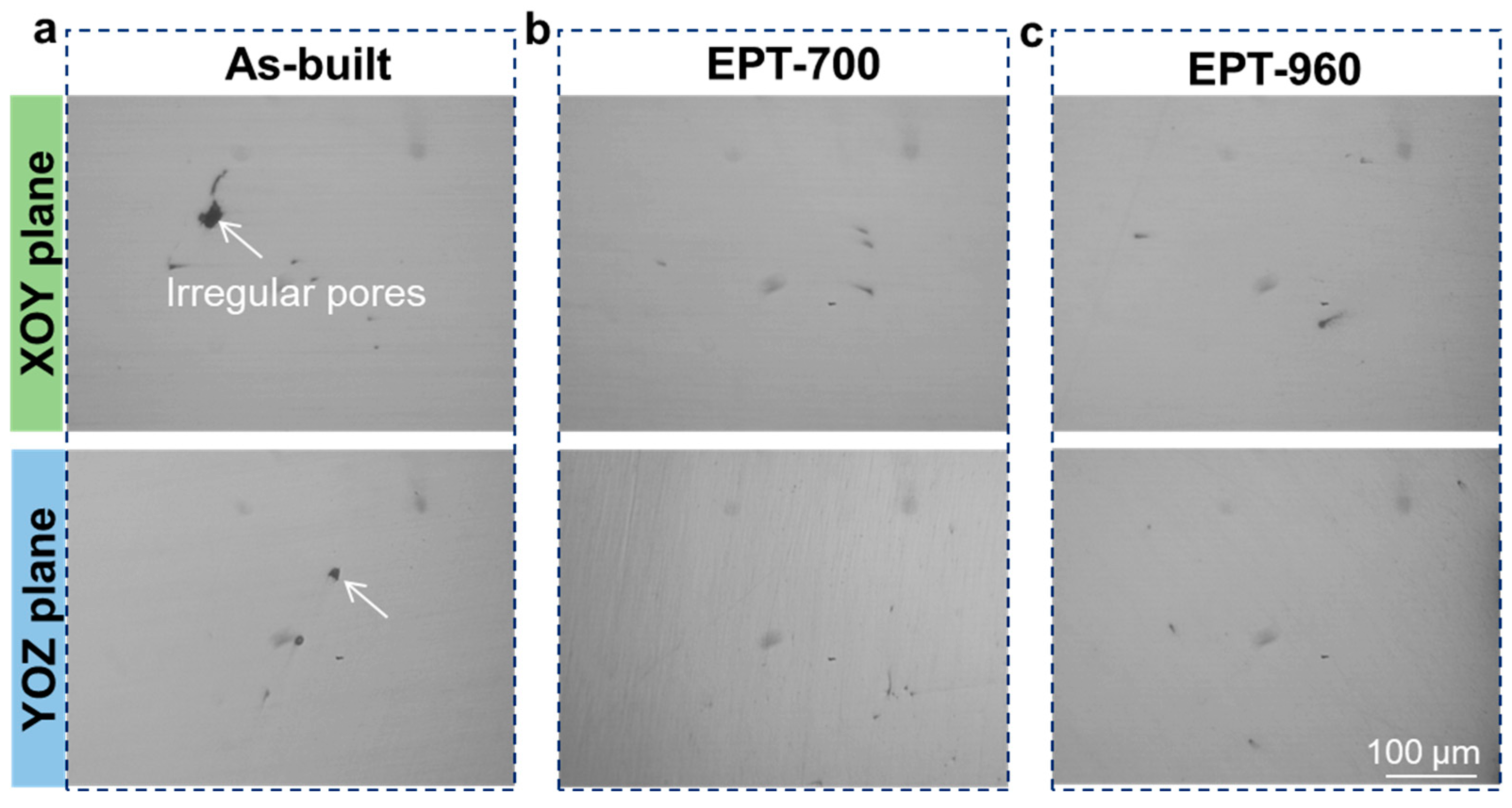
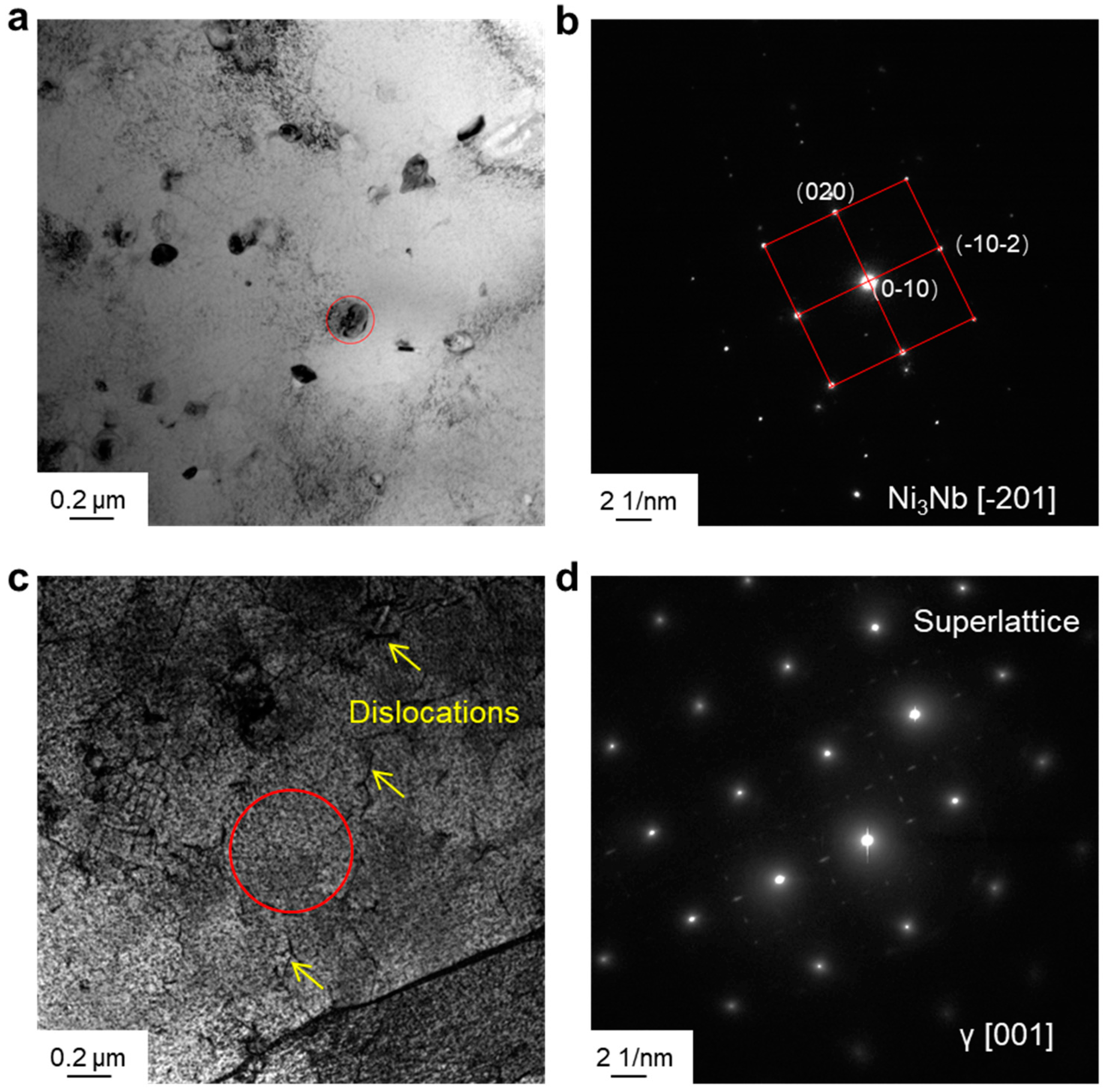
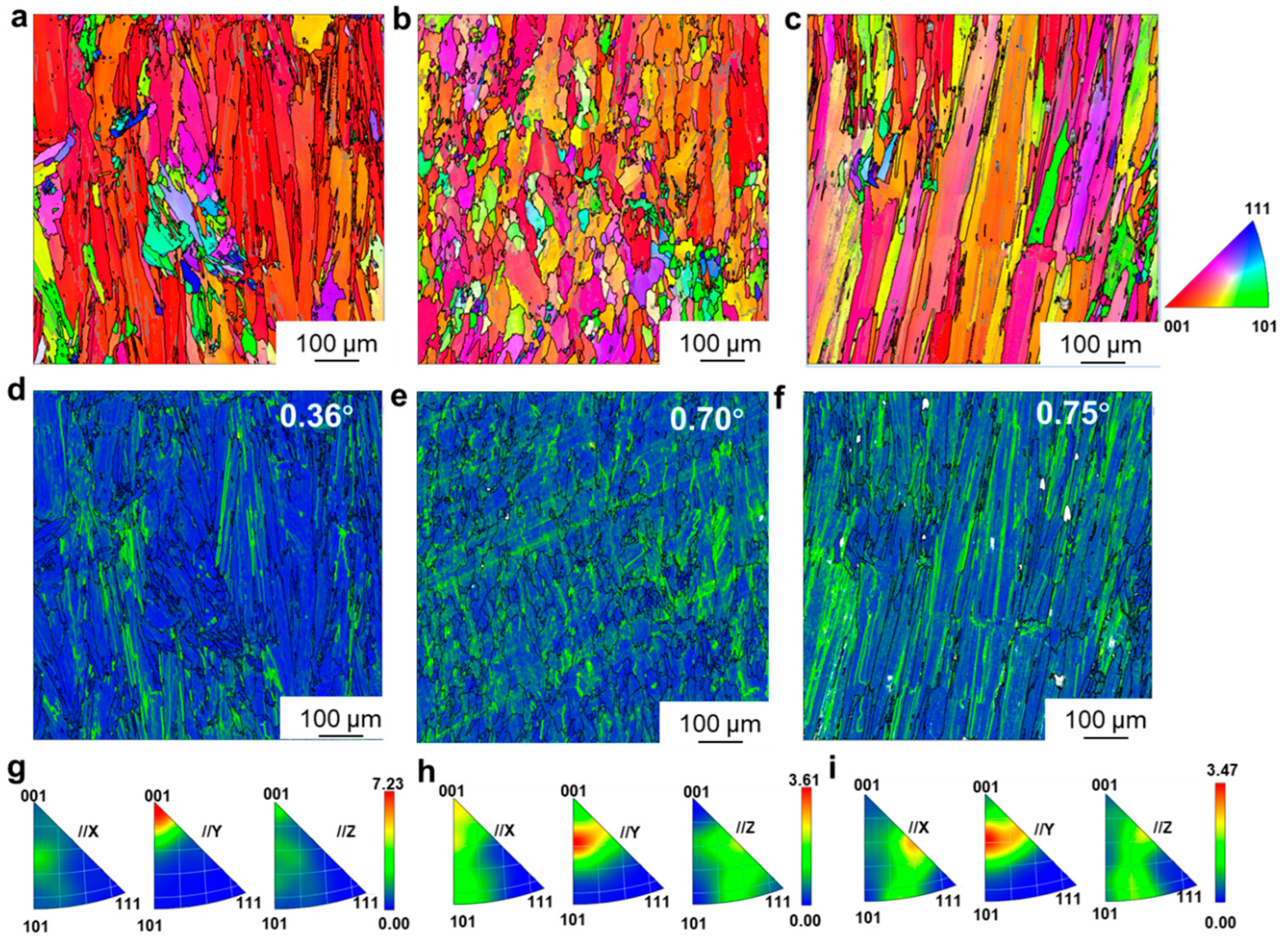
3.1. Microstructure
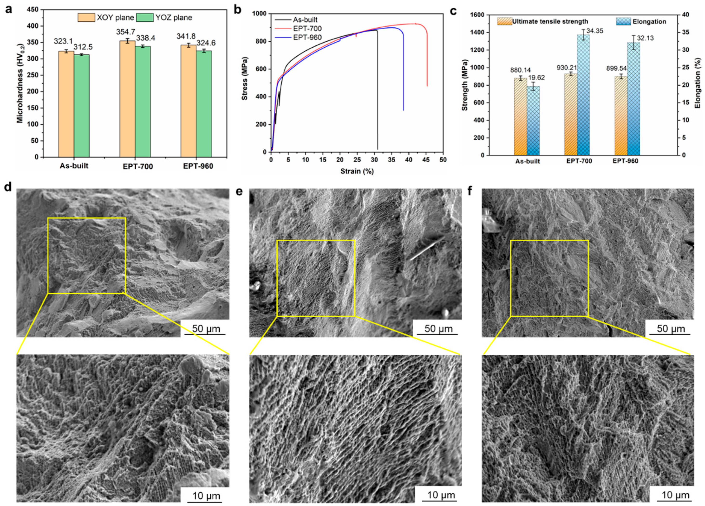
3.2. Mechanical Properties
4. Conclusions
Author Contributions
Funding
Institutional Review Board Statement
Informed Consent Statement
Data Availability Statement
Conflicts of Interest
References
- Shahwaz, M.; Nath, P.; Sen, I. A critical review on the microstructure and mechanical properties correlation of additively manufactured nickel-based superalloys. J. Alloys Compd. 2022, 907, 164530. [Google Scholar] [CrossRef]
- Tang, Z.; Yang, C.; Duan, Y.; Ma, L.; Zheng, S.; Li, M. Corrosion and wear behaviors of Inconel 718 nickel-based alloy by boroaluminizing. Surf. Coat. Technol. 2024, 478, 130500. [Google Scholar] [CrossRef]
- Meng, G.; Gong, Y.; Zhang, J.; Jiang, Z.; Ren, Q.; Zhao, J. Microstructure and mechanical properties of Inconel 718 thin walls prepared by laser direct energy deposition and selective laser melting. Thin-Walled Struct. 2023, 193, 111284. [Google Scholar] [CrossRef]
- Juillet, C.; Oudriss, A.; Balmain, J.; Feaugas, X.; Pedraza, F. Characterization and oxidation resistance of additive manufactured and forged IN718 Ni-based superalloys. Corros. Sci. 2018, 142, 266–276. [Google Scholar] [CrossRef]
- Liu, Y.; Guo, Q.; Li, C.; Mei, Y.; Zhou, X.; Huang, Y.; Li, H. Recent progress on evolution of precipitates in inconel 718 superalloy. Acta Metall. Sin. 2016, 52, 1259–1266. [Google Scholar]
- Zhang, H.; Li, C.; Liu, Y.; Guo, Q.; Li, H. Precipitation behavior during high-temperature isothermal compressive deformation of Inconel 718 alloy. Mater. Sci. Eng. A 2016, 677, 515–521. [Google Scholar] [CrossRef]
- Zheng, Y.; Cao, L.; Wang, J.; Xie, J.; Chen, J.; Wang, D.; Wang, S.; Xu, J.; Lu, H. Surface morphology refinement and Laves phase control of plasma arc additively manufactured Inconel 718 via an alternating magnetic field. Mater. Des. 2022, 223, 111161. [Google Scholar] [CrossRef]
- Deng, H.; Wang, L.; Liu, Y.; Song, X.; Meng, F.; Huang, S. The evolution law of δ phase of IN718 superalloy in temperature/stress coupled field. Mater. Charact. 2022, 184, 111684. [Google Scholar] [CrossRef]
- Liu, Y.; Zhang, H.; Guo, Q.; Zhou, X.; Ma, Z.; Huang, Y.; Li, H. Microstructure evolution of Inconel 718 superalloy during hot working and its recent development tendency. Acta Metall. Sin. 2018, 54, 1653–1664. [Google Scholar]
- Gao, Y.; Zhang, D.; Cao, M.; Chen, R.; Feng, Z.; Poprawe, R.; Schleifenbaum, J.H.; Ziegler, S. Effect of δ phase on high temperature mechanical performances of Inconel 718 fabricated with SLM process. Mater. Sci. Eng. A 2019, 767, 138327. [Google Scholar] [CrossRef]
- Singh, V.K.; Sahoo, D.; Amirthalingam, M.; Karagadde, S.; Mishra, S.K. Dissolution of the Laves phase and δ-precipitate formation mechanism in additively manufactured Inconel 718 during post printing heat treatments. Addit. Manuf. 2024, 81, 104021. [Google Scholar] [CrossRef]
- Zhang, H.; Li, C.; Guo, Q.; Ma, Z.; Huang, Y.; Li, H.; Liu, Y. Hot tensile behavior of cold-rolled Inconel 718 alloy at 650 °C: The role of δ phase. Mater. Sci. Eng. A 2018, 722, 136–146. [Google Scholar] [CrossRef]
- Damodaram, R.; Raman, S.G.S.; Rao, K.P. Microstructure and mechanical properties of friction welded alloy 718. Mater. Sci. Eng. A 2013, 560, 781–786. [Google Scholar] [CrossRef]
- Mostafa, A.; Picazo Rubio, I.; Brailovski, V.; Jahazi, M.; Medraj, M. Structure, texture and phases in 3D printed IN718 alloy subjected to homogenization and HIP treatments. Metals 2017, 7, 196. [Google Scholar] [CrossRef]
- Qin, H.; Bi, Z.; Yu, H.; Feng, G.; Du, J.; Zhang, J. Influence of stress on gamma precipitation behavior in Inconel 718 during aging. J. Alloys Compd. 2018, 740, 997–1006. [Google Scholar] [CrossRef]
- Liang, C.-L.; Lin, K.-L. The microstructure and property variations of metals induced by electric current treatment: A review. Mater. Charact. 2018, 145, 545–555. [Google Scholar] [CrossRef]
- Zhang, X.; Li, H.; Shao, G.; Gao, J.; Zhan, M. “Target effect” of pulsed current on the texture evolution behaviour of Ni-based superalloy during electrically-assisted tension. J. Alloys Compd. 2022, 898, 162762. [Google Scholar] [CrossRef]
- Jeong, K.; Jin, S.-W.; Kang, S.-G.; Park, J.-W.; Jeong, H.-J.; Hong, S.-T.; Cho, S.H.; Kim, M.-J.; Han, H.N. Athermally enhanced recrystallization kinetics of ultra-low carbon steel via electric current treatment. Acta Mater. 2022, 232, 117925. [Google Scholar] [CrossRef]
- Pan, D.; Wang, Y.; Guo, Q.; Zhang, D.; Xu, X.; Zhao, Y. Grain refinement of Al–Mg–Si alloy without any mechanical deformation and matrix phase transformation via cyclic electro-pulsing treatment. Mater. Sci. Eng. A 2021, 807, 140916. [Google Scholar] [CrossRef]
- Zhang, X.; Li, H.; Zhan, M. Mechanism for the macro and micro behaviors of the Ni-based superalloy during electrically-assisted tension: Local Joule heating effect. J. Alloys Compd. 2018, 742, 480–489. [Google Scholar] [CrossRef]
- Zhang, X.; Li, H.; Zhan, M.; Shao, G.; Ma, P. Extraordinary effect of the δ phase on the electrically-assisted deformation responses of a Ni-based superalloy. Mater. Charact. 2018, 144, 597–604. [Google Scholar] [CrossRef]
- Sarkar, D.; Kapil, A.; Sharma, A. Advances in computational modeling for laser powder bed fusion additive manufacturing: A comprehensive review of finite element techniques and strategies. Addit. Manuf. 2024, 85, 104157. [Google Scholar] [CrossRef]
- Laleh, M.; Sadeghi, E.; Revilla, R.I.; Chao, Q.; Haghdadi, N.; Hughes, A.E.; Xu, W.; De Graeve, I.; Qian, M.; Gibson, I.; et al. Heat treatment for metal additive manufacturing. Prog. Mater. Sci. 2023, 133, 101051. [Google Scholar] [CrossRef]
- Montero-Sistiaga, M.L.; Godino-Martinez, M.; Boschmans, K.; Kruth, J.-P.; Van Humbeeck, J.; Vanmeensel, K. Microstructure evolution of 316L produced by HP-SLM (high power selective laser melting). Addit. Manuf. 2018, 23, 402–410. [Google Scholar] [CrossRef]
- Bandyopadhyay, A.; Traxel, K.D.; Lang, M.; Juhasz, M.; Eliaz, N.; Bose, S. Alloy design via additive manufacturing: Advantages, challenges, applications and perspectives. Mater. Today 2022, 52, 207–224. [Google Scholar] [CrossRef]
- Takata, N.; Kodaira, H.; Sekizawa, K.; Suzuki, A.; Kobashi, M. Change in microstructure of selectively laser melted AlSi10Mg alloy with heat treatments. Mater. Sci. Eng. A 2017, 704, 218–228. [Google Scholar] [CrossRef]
- Montero Sistiaga, M.; Nardone, S.; Hautfenne, C.; Van Humbeeck, J. Effect of heat treatment of 316L stainless steel produced by selective laser melting (SLM). In Proceedings of the 27th Annual International Solid Freeform Fabrication Symposium—An Additive Manufacturing Conference, Austin, TX, USA, 8–10 August 2016. [Google Scholar]
- Troitskii, O.A. Electroplastic deformation of metal. Strength Mater. 1976, 8, 1466–1471. [Google Scholar] [CrossRef]
- Troitskii, O. Electromechanical effect in metals. ZhETF Pisma Redaktsiiu 1969, 10, 18. [Google Scholar]
- Ran, M.; Bian, G.; Zhang, H.; Yan, J.; Wang, W. Electropulsing-enhanced atomic diffusion and recrystallization to optimize mechanical properties of Al/Cu laminated metal composites. J. Manuf. Process. 2024, 119, 224–234. [Google Scholar] [CrossRef]
- Zhu, Y.; To, S.; Lee, W.B.; Liu, X.; Jiang, Y.; Tang, G. Electropulsing-induced phase transformations in a Zn–Al-based alloy. J. Mater. Res. 2009, 24, 2661–2669. [Google Scholar] [CrossRef]
- Qin, R.S. Critical Assessment 8: Outstanding issues in electropulsing processing. Mater. Sci. Technol. 2015, 31, 203–206. [Google Scholar] [CrossRef]
- Taller, S.; Austin, T. Using post-processing heat treatments to elucidate precipitatestrengthening of additively manufactured superalloy 718. Add. Manuf. 2022, 60, 103280. [Google Scholar]


Disclaimer/Publisher’s Note: The statements, opinions and data contained in all publications are solely those of the individual author(s) and contributor(s) and not of MDPI and/or the editor(s). MDPI and/or the editor(s) disclaim responsibility for any injury to people or property resulting from any ideas, methods, instructions or products referred to in the content. |
© 2024 by the authors. Licensee MDPI, Basel, Switzerland. This article is an open access article distributed under the terms and conditions of the Creative Commons Attribution (CC BY) license (https://creativecommons.org/licenses/by/4.0/).
Share and Cite
Zhang, H.; Liu, J.; Wang, Z. Effect of Electric Pulse Treatment on Microstructure and Mechanical Property of Laser Powder Bed Fused IN718. Metals 2024, 14, 751. https://doi.org/10.3390/met14070751
Zhang H, Liu J, Wang Z. Effect of Electric Pulse Treatment on Microstructure and Mechanical Property of Laser Powder Bed Fused IN718. Metals. 2024; 14(7):751. https://doi.org/10.3390/met14070751
Chicago/Turabian StyleZhang, Hongmei, Jie Liu, and Zhanfeng Wang. 2024. "Effect of Electric Pulse Treatment on Microstructure and Mechanical Property of Laser Powder Bed Fused IN718" Metals 14, no. 7: 751. https://doi.org/10.3390/met14070751
APA StyleZhang, H., Liu, J., & Wang, Z. (2024). Effect of Electric Pulse Treatment on Microstructure and Mechanical Property of Laser Powder Bed Fused IN718. Metals, 14(7), 751. https://doi.org/10.3390/met14070751