Abstract
Molybdenum diselenide (MoSe2) is a promising anode for alkali-ion storage due to its intrinsic advantages. However, MoSe2 still encounters the issues of structural instability and poor rate performance caused by drastic volume change and sluggish reaction kinetics. Reasonable design of electrode structure is crucial for achieving superior electrochemical performance. Herein, a novel hierarchical structure coupled with 1D/1D subunits is elaborately designed and constructed, in which the MoSe2/CoSe2 heterostructure is the “trunk” and the N-doped carbon nanotubes are the “branches” (MoSe2/CoSe2/NCNTs). Benefiting from the properties endowed by unique configurations, MoSe2/CoSe2/NCNTs electrodes manifest faster reaction kinetics and better structure durability. Evaluated as an anode for LIBs and SIBs, MoSe2/CoSe2/NCNTs deliver high reversible capacity, superior rate capability (452 at 10 A g−1 in LIBs and 296 at 10 A g−1 in SIBs), and prominent cycle life (553 after 2000 cycles at 5 A g−1 in LIBs and 310 after 2000 cycles at 5 A g−1 in SIBs). Such design conception can also provide guidance for the development of other high-performance electrodes.
1. Introduction
Surging demand for high-energy-density lithium-ion batteries (LIBs) and sodium-ion batteries (SIBs) stimulates great interest in exploring high-performance electrode materials [1]. Among available materials, MoSe2, a typical representative of layered transition metal selenide, is considered a highly promising anode due to its large interlayer spacing and narrow band gap [2,3,4]. Unfortunately, MoSe2 electrodes still encounter fast capacity fading and poor rate capability caused by the large stress variation and sluggish kinetics during ion insertion/extraction [5,6]. Overcoming the aforementioned limitations is the key to achieving high-performance electrodes. To address these issues, various strategies have been attempted, such as element doping, the introduction of a coating layer, and the design of nanostructures [7,8,9].
Previous research has demonstrated that constructing rational electrode structures, including porous structure, defection structure, and heterostructure, is a feasible avenue to promote electrochemical performance [10,11]. Moreover, heterostructure has been recognized to facilitate reaction kinetics due to the built-in electric fields at the heterointerface [12,13]. For instance, Hong et al. investigated the ultrafast charge transfer at the MoS2/WS2 interfaces [14]. Nishitani et al. found a four-fold enhancement of electron mobility at the heterointerface of MoS2/WS2 [15]. Kong et al. coupled ZnSe and CoSe2 to induce a strong built-in electric field at the interface, achieving significant improvement in rate capability [16]. From the perspective of accelerating ion transport, the construction of a heterostructure would be an effective and feasible approach. In regard to MoSe2, selecting the appropriate hetero-phase is crucial for achieving excellent rate performance.
Although the establishment of heterostructure can successfully improve reaction kinetics, the problem of fast capacity fading caused by the large stress variation still exists in MoSe2. Integrating MoSe2 with carbon-based materials is the simplest and most feasible strategy [17]. However, just introducing a carbon coating layer on the surface of the material does not achieve optimal results. Recently, integrating the host material with carbon nanotubes to construct a hierarchical branched structure has evoked attention because it can provide massive channels for ion diffusion while alleviating stress variation [18,19,20]. Moreover, the mutual entanglement between radial “branches” can also build a suitable conductive network, promoting the conductivity of materials [21,22]. It follows that constructing hierarchical branched structures composed of MoSe2 composite and carbon nanotubes may be a more ideal route to tackle the issue of fast capacity fading. However, to our knowledge, there are few reports on the construction of hierarchical branched structures by integrating MoSe2 composite and carbon nanotubes.
Herein, we constructed a novel hierarchical branched structure that utilizes MoSe2/CoSe2 as the “trunk” and N-doped carbon nanotubes as the “branches” (MoSe2/CoSe2/NCNTs). Such a unique structure combines several significant advantages: (i) the built-in electric field at the heterointerface can boost ion transport, improving rate performance; (ii) abundant heterointerface can also store additional Li+/Na+ ions, promoting reversible capacity; and (iii) external NCNTs not only alleviate volume change but also provide numerous pathways for ion/electron transport. Profiting from these advantages, MoSe2/CoSe2/NCNTs deliver superior rate capability and outstanding cycling stability. When the current density reaches 10 A g−1, MoSe2/CoSe2/NCNTs exhibit high capacities of 452 mAh g−1 in LIBs and 296 mAh g−1 in SIBs, respectively. Even after 2000 cycles at a current density of 5 A g−1, MoSe2/CoSe2/NCNTs can still maintain capacities of 553 mAh g−1 in LIBs and 310 mAh g−1 in SIBs. This novel design concept provides a new avenue for developing high-performance electrode materials.
2. Materials and Methods
2.1. Materials Synthesis
Synthesis of MoO3 nanorods and MoSe2 nanorods: In a typical procedure, 1.4 g of ammonium heptamolybdate tetrahydrate ((NH4)6Mo7O24·4H2O) (Aladdin Reagent (Shanghai) Co., Ltd., Shanghai, China) was dissolved in 40 mL nitric acid (2.4 mol·L−1) (Aladdin Reagent (Shanghai) Co., Ltd., Shanghai, China) under stirring before being transferred into a Teflon-lined stainless steel autoclave of 50 mL capacity. Then, the autoclave was sealed and heated at 200 °C in an oven for 20 h. When the vessel was cooled down to room temperature naturally, the MoO3 nanorods were collected by centrifugation and washed with water and ethanol several times before drying overnight at 60 °C. MoO3 nanorods and Se powders with a mass ratio of 1:5 were separately placed in a quartz boat with Se powders at the upstream side. Then, MoSe2 nanorods were obtained after annealing at 500 °C for 2 h at a ramp rate of 5 °C/min−1 in Ar.
Synthesis of MoO3 coated by ZIF-67 (MoO3@ZIF-67): In a typical procedure, 0.2 g MoO3 nanorods and 0.58 g Co(NO3)2·6H2O (Shanghai Macklin Biochemical Co., Ltd., Shanghai, China) were dispersed in 20 mL methanol through ultrasonication, named solution A. Meanwhile, 1.3 g dimethyl imidazole (Shanghai Macklin Biochemical Co., Ltd., Shanghai, China) was dissolved in 20 mL methanol by stirring, named solution B. Subsequently, solution B was added into solution A, stirred for 5 min, and stood for 1 h. Finally, the precipitate was collected by centrifugation, washed, and dried to obtain MoO3@ZIF-67.
Synthesis of MoSe2/CoSe2 nanoparticles and N-doped carbon nanotubes composite (MoSe2/CoSe2/NCNTs): The preparation of MoSe2/CoSe2/NCNTs mainly involves a two-step heat treatment process. Firstly, MoO3@ZIF-67 was annealed at 750 °C for 3 h at a ramp rate of 5 °C/min−1 in 5% H2/Ar to obtain the Mo/Co nanoparticles and N-doped carbon nanotubes composite (Mo/Co/NCNTs). Secondly, Mo/Co/NCNTs and Se powders with a mass ratio of 1:5 were separately placed in a quartz boat with Se powders at the upstream side. Finally, MoSe2/CoSe2/NCNTs were obtained after annealing at 500 °C for 2 h at a ramp rate of 5 °C/min−1 in Ar.
Synthesis of CoSe2 nanoparticles and N-doped carbon composite (CoSe2/NC): In a typical procedure, 0.58 g Co(NO3)2·6H2O was dispersed in 20 mL methanol, named solution A. Meanwhile, 1.3 g dimethyl imidazole was dissolved in 20 mL methanol, named solution B. Subsequently, add solution B to solution A and stir for 5 min, then let it stand for 24 h. Then, the precipitate was collected by centrifugation, washed, and dried to obtain ZIF-67. Finally, ZIF-67 and Se powders with a mass ratio of 1:5 were separately placed in a quartz boat with Se powders at the upstream side. The CoSe2/NC was obtained after annealing at 500 °C for 2 h at a ramp rate of 5 °C/min−1 in Ar.
Synthesis of MoSe2/CoSe2 nanoparticles and N-doped carbon composite (MoSe2/CoSe2/NC): The preparation of MoSe2/CoSe2/NC only involves one step heat treatment process. MoO3@ZIF-67 and Se powders with a mass ratio of 1:5 were separately placed in a quartz boat with Se powders at the upstream side. Then, MoSe2/CoSe2/NC was obtained after annealing at 500 °C for 2 h at a ramp rate of 5 °C/min−1 in Ar.
2.2. Material Characterizations
The composition and purity of the material were characterized by X-ray diffraction (XRD) on a Rigaku D/max-2000 diffractometer with Cu Kα radiation (Bruker (Beijing) Scientific Technology Co., Ltd., Beijing, China). Raman spectra were tested on a Renishaw inVia micro-Raman spectroscopy system with a laser wavelength of 532 nm (Renishaw (Shanghai) Trading Co., Ltd., Shanghai, China). The micromorphology was characterized by a HELIOS NanoLab 600i field emission scanning electron microscope (FE-SEM) (Hitachi Analytical Instruments (Shanghai) Co., Ltd., Shanghai, China). The operating voltage was set to 20 kV, and the samples were prepared by dropping the pre-ultrasonic-dispersed (10 min) ethanol turbid liquid onto the chip of silicon. Transmission electron microscopy (TEM) and high-resolution TEM (HRTEM) of the samples were performed on an FEI Tecnai G2 F30 S-Twin operating at 300 kV (Thermo Fisher Scientific, Waltham, MA, USA). X-ray photoelectron spectroscopy (XPS) was accomplished using a Thermo Scientific ESCALAB 250Xi X-ray photoelectron spectrometer with a pass energy of 20.00 eV and an Al Kα excitation source (1486.6 eV) (Thermo Fisher Scientific, Waltham, MA, USA). Combined DTA-TG measurement was conducted in a SETARAM DSC-141 at a heating rate of 10 K min−1 in an air atmosphere (Shimadzu Corporation, Kyoto, Japan). Brunauer–Emmett–Teller (BET) data were obtained with a Micromeritics ASAP 2020 (Accelerated Surface Area and Porosimetry System) (Best Instrument Technology (Beijing) Co., Ltd., Beijing, China).
2.3. Electrochemical Measurements
The electrochemical evaluation was performed on 2025-type coin cells. The prepared electrode material, carbon black, and poly(vinyl difluoride) (PVDF) were mixed in a weight ratio of 8:1:1. Slurry of the mixture was stirred for 12 h and pasted on copper foil, followed by the electrode film being dried in vacuum at 120 °C for 12 h. The average mass loading of active materials was ∼1.5 mg cm−2. For LIBs cell, lithium foil was used as the counter electrode and the LiPF6 in ethylene carbonate/diethyl carbonate (EC:DEC = 1:1 v/v) as the electrolyte. For SIBs cell, the electrolyte was 1 M NaClO4 in ethylene carbonate/dimethyl carbonate (EC:DMC = 1:1 v/v) with 5 wt% fluoroethylene carbonate. Sodium metal and glass fiber were used as the counter electrode and the separator, respectively. Cell assembly was performed in a glovebox. The cyclic voltammetry (CV) and electrochemical impendence spectroscopy (EIS) measurements were performed on a CHI604C electrochemical workstation with a voltage range from 3.0 to 0.01 V at a scanning rate of 0.5 mV s−1. The galvanostatic charge/discharge measurements were performed on a battery testing system (NEWARE BTS-610) with a voltage of 0.01–3.0 V. For the GITT tests, the cell was discharged/charged at 0.1 A g−1 with a current pulse duration of 0.5 h and interval time of 2 h.
3. Results and Discussion
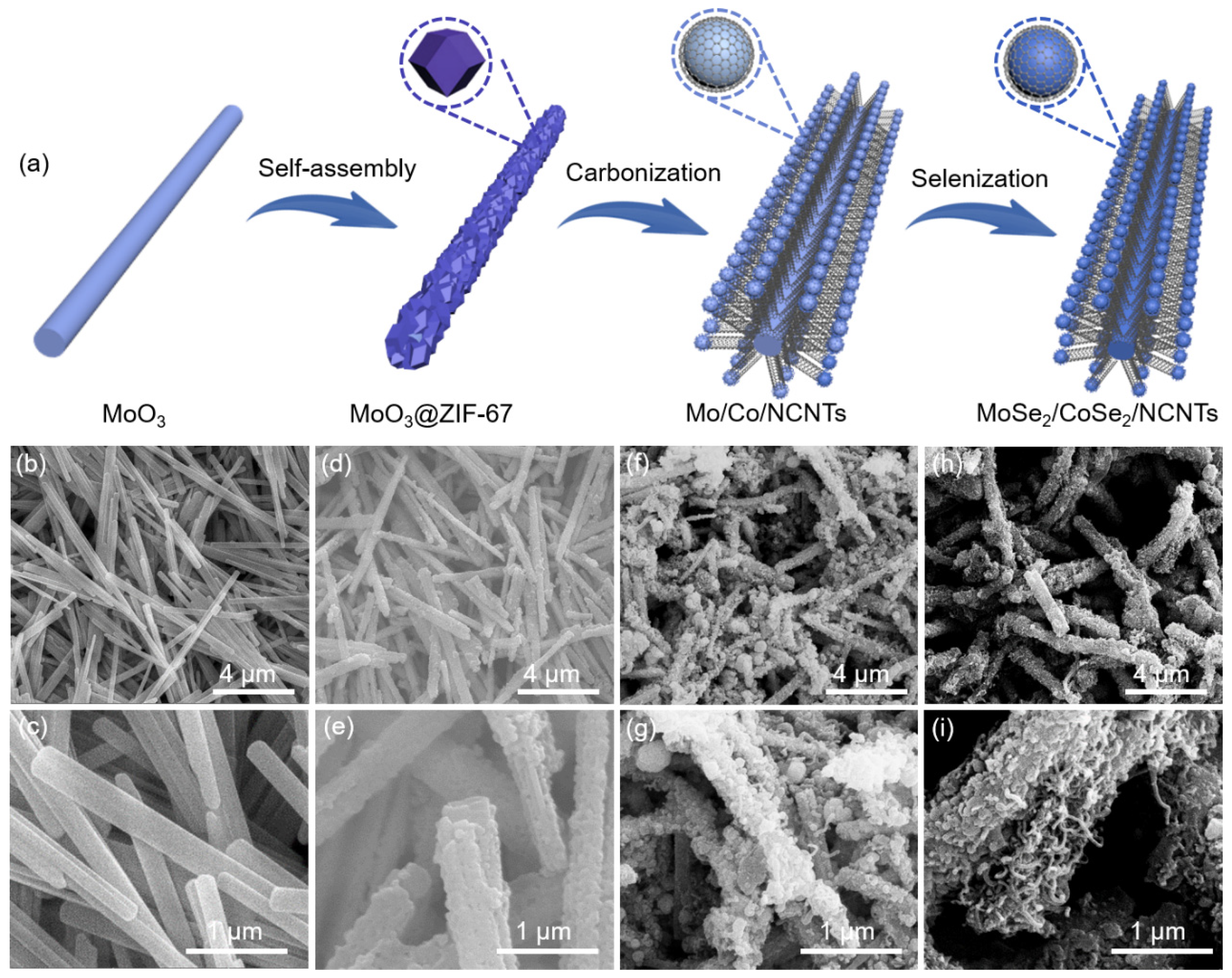
As displayed in Figure 1a, the synthesis of MoSe2/CoSe2/NCNTs mainly involves three stages. Firstly, a layer of cobalt-based metal–organic framework ZIF-67 was coated outside the MoO3 nanorods via coordination reactions between Co2+ and organic ligands, which can be observed by scanning electron microscopy (SEM) images. Compared to pure MoO3 nanorods (Figure 1b,c), a porous coating layer on the outside of the MoO3@ZIF-67 can be obviously observed (Figure 1d,e). Subsequently, the obtained MoO3@ZIF-67 was carbonized in H2/Ar atmosphere. During this process, organic ligands serve as carbon sources, and metal ions are reduced to Mo/Co nanoparticles. The catalytic effect of metallic Co/Mo induces the transformation of the carbon matrix into carbon nanotubes, thereby forming a hierarchical branched structure (Figure 1f,g). Finally, the MoSe2/CoSe2/NCNTs were successfully prepared through a selenization process (Figure 1h,i). As a comparison, MoSe2, CoSe2/NC, and MoSe2/CoSe2/NC were synthesized via direct selenizing MoO3 nanorods, ZIF-67, and MoO3@ZIF-67 (Figures S1–S3).
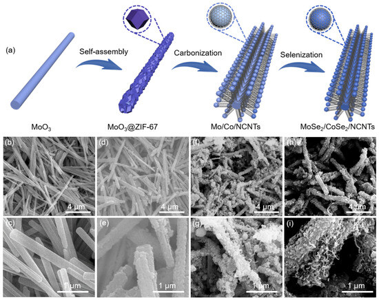
Figure 1.
(a) Schematic illustration of the synthesis of the MoSe2/CoSe2/NCNTs, SEM images of (b,c) MoO3, (d,e) MoO3@ZIF-67, (f,g) Mo/Co/NCNTs, and (h,i) MoSe2/CoSe2/NCNTs.
The microstructure of MoSe2/CoSe2/NCNTs was investigated by transmission electron microscopy (TEM). As shown in Figure 2a,b and Figure S4a, MoSe2/CoSe2/NCNTs display a hierarchical branched structure composed of nanorods and carbon nanotubes, in which a large number of nanoparticles are encapsulated in the nanorods. The HRTEM displays the presence of three orientations of lattice fringes in the MoSe2/CoSe2/NCNTs (Figure 2c). Fast Fourier transform was performed on regions 1, 2, and 3 in Figure 2c, respectively. The lattice fringe with a spacing of 0.646 nm in Figure 2d corresponds to the (003) plane of MoSe2. The lattice fringes with spacing of 0.260 and 0.238 nm in Figure 2e,f correspond to the (210) and (211) planes of CoSe2, respectively. The heterointerface between MoSe2 and CoSe2 can be clearly observed from Figure 2c and Figure S4b. The energy-dispersive X-ray (EDX) line profiles demonstrate that Mo, Co, Se, C, and N elements are well dispersed throughout the material (Figure 2g,h).
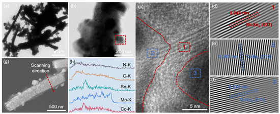
Figure 2.
Microstructure analysis of MoSe2/CoSe2/NCNTs: (a,b) TEM images (red dashed square: the enlarged area is shown in Figure 2c), (c) HRTEM image (red dashed line is the heterointerface between MoSe2 and CoSe2), (d–f) inverse-FFT images of regions 1, 2, and 3, (g) HAADF image, and (h) EDX line profile.
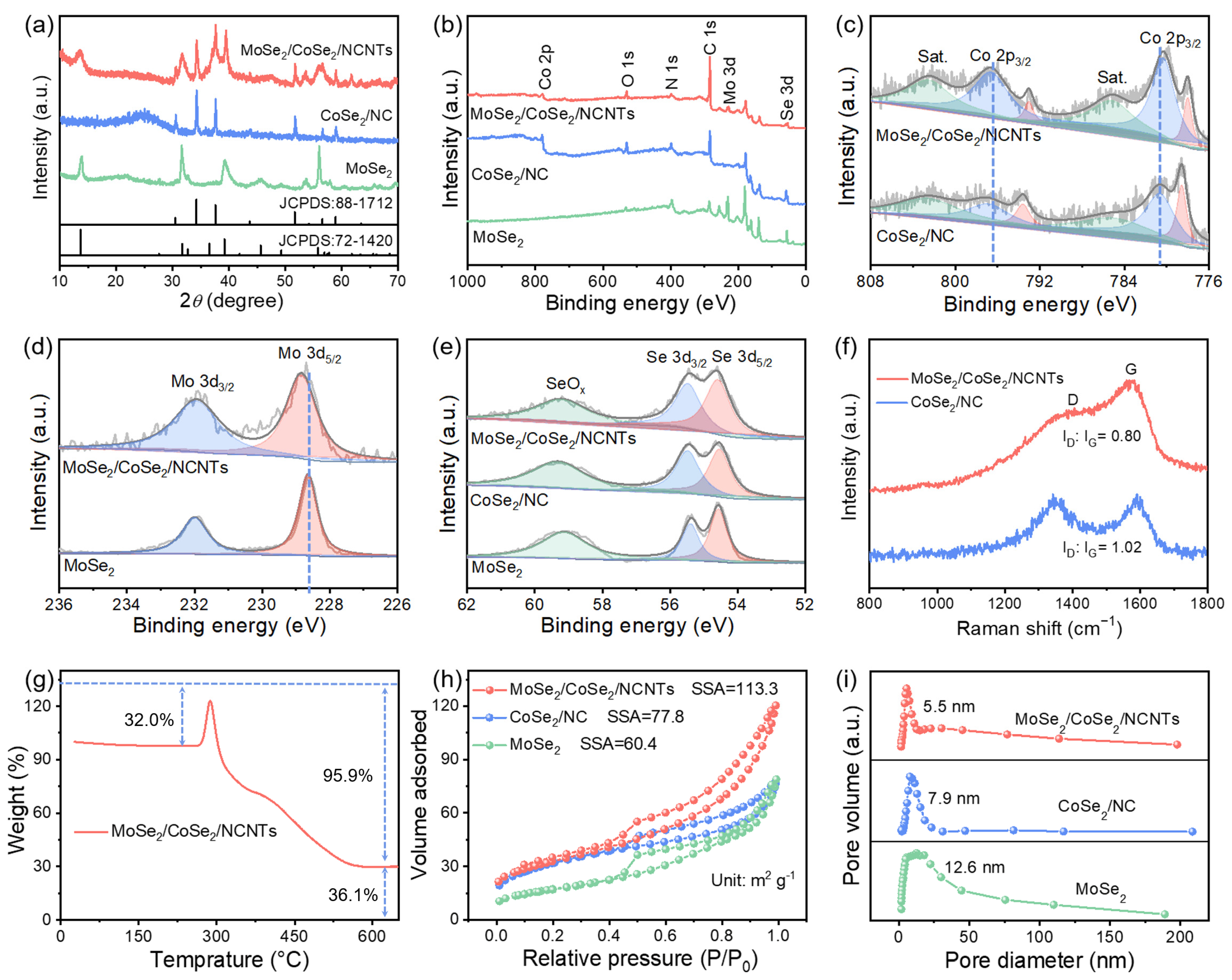
To investigate the crystal structure of the samples, powder X-ray diffraction (XRD) was conducted. As shown in Figure 3a and Figure S5, the diffraction peaks of MoSe2/CoSe2/NCNTs and MoSe2/CoSe2/NC can be well indexed to hexagonal MoSe2 (JCPDS: 72-1420) and cubic CoSe2 (JCPDS: 88-1712), proving the coexistence of two phases. The surface elemental composition of the samples was studied using X-ray photoelectron spectroscopy (XPS). Figure 3b displays the survey spectra of MoSe2/CoSe2/NCNTs, CoSe2/NC, and MoSe2, demonstrating the existence of Mo, Co, Se, C, and N in MoSe2/CoSe2/NCNTs. The appearance of the O 1s characteristic peak can be ascribed to the slight oxidation of the sample due to exposure to the air. Compared with CoSe2/NC and MoSe2, the Co 2p3/2 characteristic peak of MoSe2/CoSe2/NCNTs shifts toward low binding energy (Figure 3c), while the Mo 3d5/2 characteristic peak shifts toward high binding energy (Figure 3d), indicating the existence of interaction between CoSe2 and MoSe2 at the heterointerface, which may be due to the formation of Mo-Se-Co bonds [23,24]. The characteristic peak of SeOx is caused by the surface oxidation of the sample (Figure 3e) [25]. Figure 3f exhibits the Raman spectra of MoSe2/CoSe2/NCNTs and CoSe2/NC. The ID/IG value of MoSe2/CoSe2/NCNTs is significantly lower than that of CoSe2/NC, demonstrating a higher graphitization degree of carbon matrix in MoSe2/CoSe2/NCNTs, which is beneficial for the promotion of conductivity [26]. The increase in weight in the TG curve is mainly due to the conversion of MoSe2 and CoSe2 into metal oxides, while the decrease in weight is due to the combustion of the carbon matrix (Figure 3g) [27]. According to calculations, the mass percent of MoSe2, CoSe2, and carbon matrix in the MoSe2/CoSe2/NCNTs is approximately 40%, 38%, and 22%, respectively (the detailed calculation process is presented in SI). A nitrogen adsorption/desorption test was conducted to investigate the specific surface area (SSA) and pore size of samples. Figure 3h,i reveal that MoSe2/CoSe2/NCNTs possess a larger SSA of 113.3 m2 g−1 and a smaller pore size of 5.5 nm compared to CoSe2/NC and MoSe2.
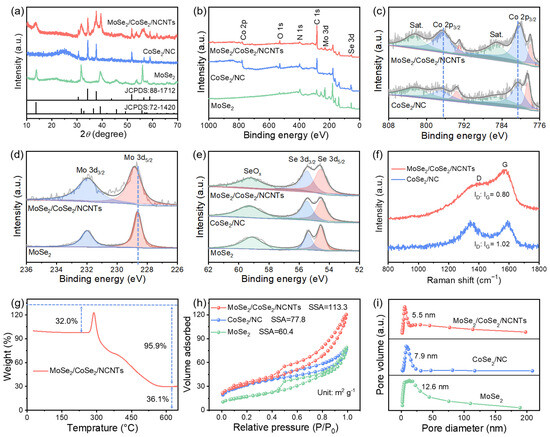
Figure 3.
Structural characterization of the MoSe2/CoSe2/NCNTs, CoSe2/NC, and MoSe2: (a) XRD patterns, (b) XPS wide spectra, (c) Co 2p spectra, (d) Mo 3d spectra, (e) Se 3d spectra, (f) Raman spectra, (g) TG curve, (h) N2 adsorption–desorption isotherms, and (i) pore size distribution.
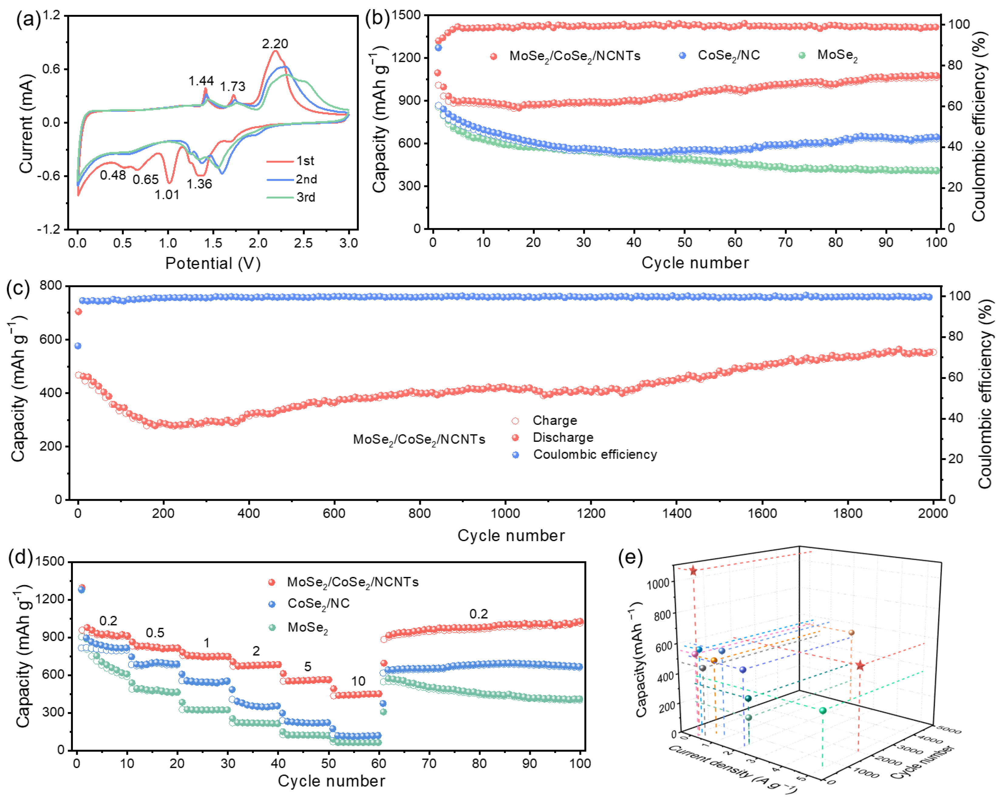
To understand the relationship between structure and electrochemical performance, the electrochemical performance of samples was first evaluated in LIBs. Figure 4a and Figure S6 present the cyclic voltammetry (CV) curves of four samples, which can be used to analyze the electrochemical reaction process of electrodes. By comparison, it can be seen that the peaks at 1.36 V and 1.01 V mainly stem from the reduction reaction of CoSe2 to metallic Co, while the peaks at 0.65 V and 0.48 V belong to the reduction reaction of MoSe2 to metallic Mo [28,29]. The peaks at 1.44 V and 1.73 V stem from the conversion of metallic Mo to MoSe2, while the peak at 2.20 corresponds to the conversion of metallic Co to CoSe2 [2,30]. As depicted in Figure S7, the initial coulombic efficiency (ICE) of MoSe2/CoSe2/NCNTs is 77%, which is higher than the ICE of MoSe2/CoSe2/NC, CoSe2/NC, and MoSe2.
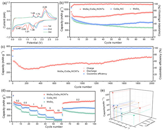
Figure 4.
Electrochemical performances of electrodes in LIBs: (a) CV curves of MoSe2/CoSe2/NCNTs at a scan rate of 0.5 mV s−1 from 0.01 to 3.0 V, (b) cycling performances of MoSe2/CoSe2/NCNTs, CoSe2/NC, and MoSe2 at a current density of 0.2 A g−1, (c) cycling performance of MoSe2/CoSe2/NCNTs at a current density of 5 A g−1, (d) rate performances of MoSe2/CoSe2/NCNTs, CoSe2/NC and MoSe2 at different current densities of 0.2–10 A g−1, and (e) comparison of performances between MoSe2/CoSe2/NCNTs and the previously reported literature (Pentagram represents this work, others adapted from Refs. [2,3,4,28,29,30,31,32,33]).
The cycling performances of four electrodes are exhibited in Figure 4b and Figure S8a. MoSe2/CoSe2/NCNTs show significant advantages in both cycling stability and reversible capacity compared to the other three electrodes. The discharge capacity of MoSe2/CoSe2/NCNTs remains at 1076 mAh g−1 after 100 cycles at a current density of 0.2 A g−1. Even after 2000 cycles at a higher current density of 5 A g−1, it can still maintain a high capacity of 553 mAh g−1 (Figure 4c). Outstanding cycling stability mainly comes from the protective effect of a carbon framework in the hierarchical branched structure. The rate performance of electrodes is crucial for high-power applications. Figure 4d and Figure S8b show that the rate performance of MoSe2/CoSe2/NCNTs is obviously superior to that of MoSe2/CoSe2/NC, CoSe2/NC, and MoSe2. Even at a current density of 10 A g−1, the capacity can still reach 452 mAh g−1. When the current density returns to 0.2 A g−1, the capacity of MoSe2/CoSe2/NCNTs can be fully restored, demonstrating exceptional rate capability. The enhancement of rate performance is mainly attributed to the acceleration effect of a built-in electric field at the heterointerface, numerous ion transport pathways provided by the hierarchical branched structure, and enhanced conductivity caused by NCNTs. By comparison, it can be found that the Li-ion storage performance of MoSe2/CoSe2/NCNTs is better than the previously reported MoSe2-based composite (Figure 4e and Table S1) [2,3,4,28,29,30,31,32,33].
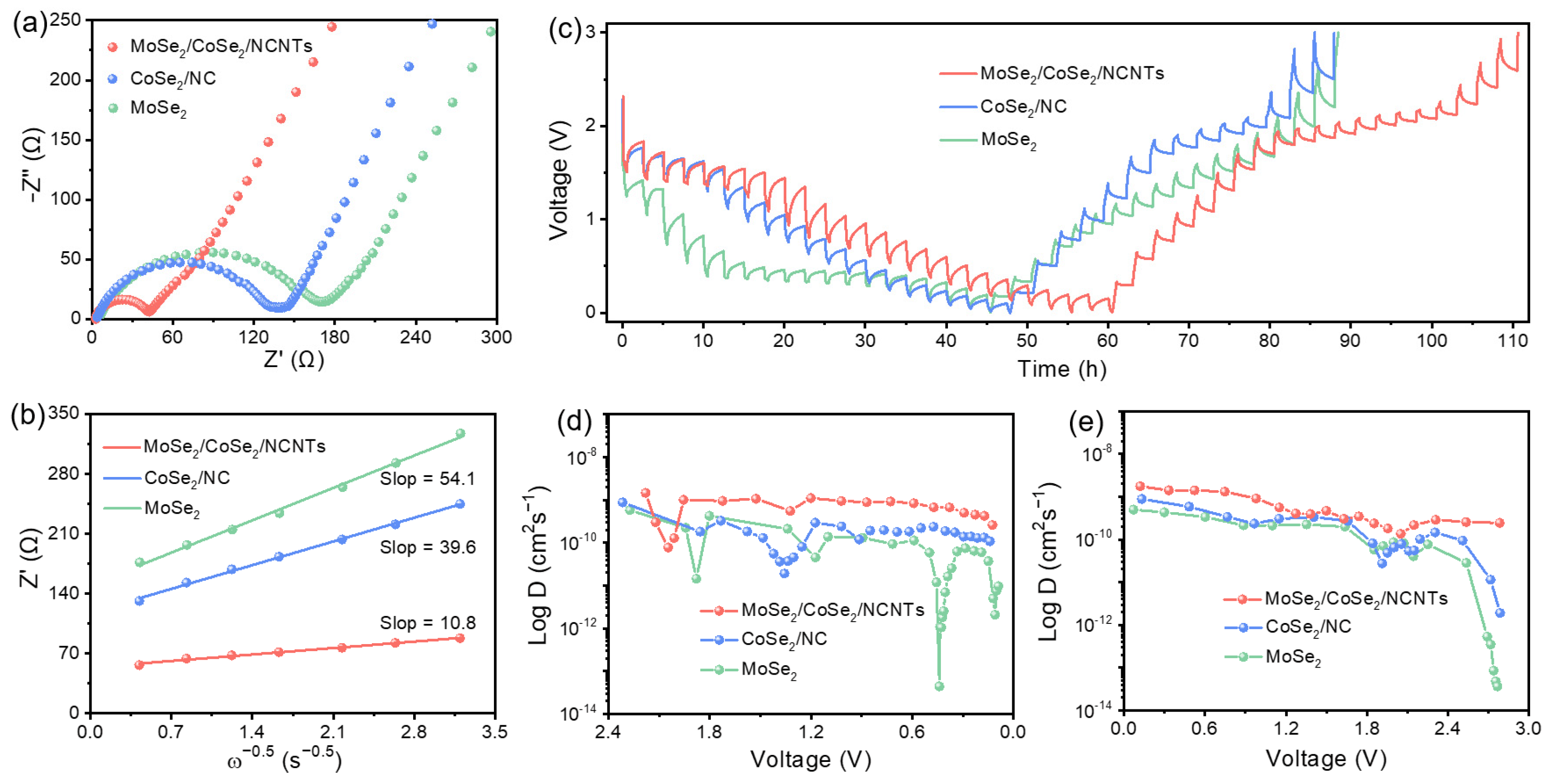
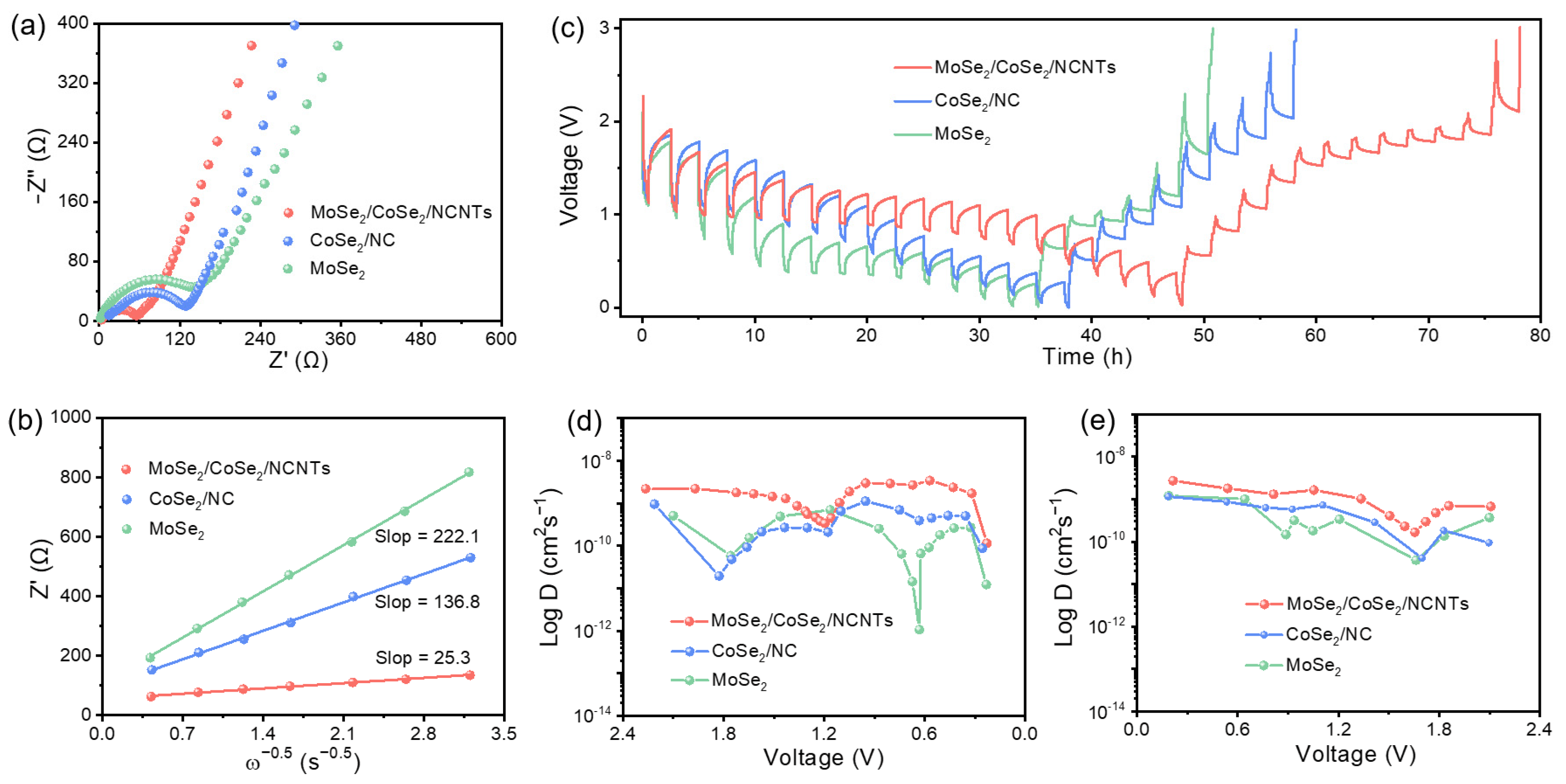
As is well known, the electrochemical performance of electrodes is closely related to the diffusion kinetics of metal ions. To comprehensively grasp the diffusion state of metal ions inside the electrodes, electrochemical impedance spectroscopy (EIS) and galvanostatic intermittent titration technique (GITT) measurements were employed to estimate metal ionic diffusion coefficients. As depicted in Figure 5a and Figure S9b, the charge transfer resistance (Rct) of MoSe2/CoSe2/NCNTs is smaller than that of the other three electrodes. The relationship between Warburg impedance coefficients and frequency can be obtained by fitting the straight lines of a Nyquist plot. Compared with MoSe2/CoSe2/NC, CoSe2/NC, and MoSe2, MoSe2/CoSe2/NCNTs also have smaller Warburg impedance coefficients, reflecting the faster ion diffusion rate (Figure 5b and Figure S9b). The GITT curves of four electrodes are exhibited in Figure 5c and Figure S11. According to calculation, the ion diffusion rate inside the bulk phase during charging/discharging can be determined (the detailed calculation process is presented in Figure S10). As demonstrated in Figure 5d,e, the Li+-ion diffusion coefficient of MoSe2/CoSe2/NCNTs fluctuates between 7.7 × 10⁻¹¹ and 1.5 × 10⁻⁹ during discharging, while it fluctuates between 2.3 × 10⁻¹⁰ and 1.8 × 10⁻⁹ during charging. In short, no matter in discharging process or charging process, the Li+-ion diffusion coefficient of MoSe2/CoSe2/NCNTs is always higher than that of MoSe2/CoSe2/NC, CoSe2/NC, and MoSe2 (Figure 5d,e and Figure S12), which is also the root cause of why MoSe2/CoSe2/NCNTs have better rate performance.
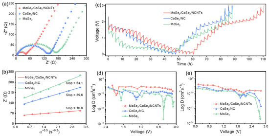
Figure 5.
Kinetics characterization of electrodes in LIBs: (a) Nyquist plots after 100 cycles, (b) the relationship between Zre and ω−1/2, (c) GITT curves at the 5th discharge and charge process, and (d,e) corresponding Li+-ion diffusion coefficients.
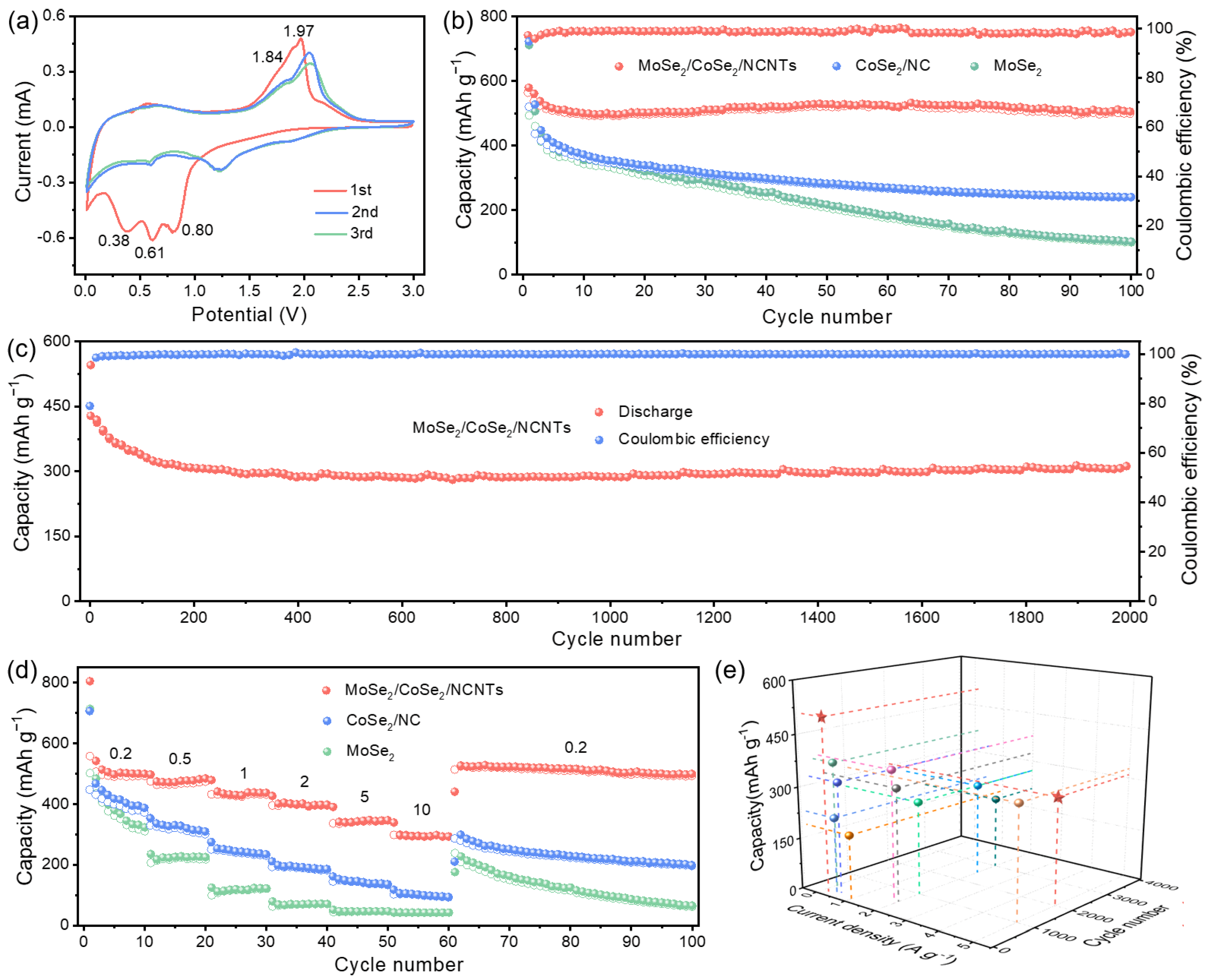
Subsequently, the Na+-ion storage performance of electrode materials was also systematically evaluated. Figure 6a and Figure S12 present the CV curves of MoSe2/CoSe2/NCNTs, MoSe2/CoSe2/NC, CoSe2/NC, and MoSe2. The peaks at 0.80 and 0.38 V can be attributed to the reaction between MoSe2 and Na+ ion to transform into metallic Mo and Na2Se, while the peak at 0.61 V is due to the conversion of CoSe2 to metallic Co [34,35]. In the anodic scanning process, the peaks at 1.84 and 1.97 V stem from the conversion of Mo to MoSe2 and Co to CoSe2, respectively [36,37]. Almost complete overlap of two subsequent CV curves indicates a higher degree of reversibility of MoSe2/CoSe2/NCNTs. The charge/discharge profiles of four electrodes are shown in Figure S13. It should be noted that MoSe2/CoSe2/NCNTs deliver the highest initial coulombic efficiency of 76% among the four electrodes.
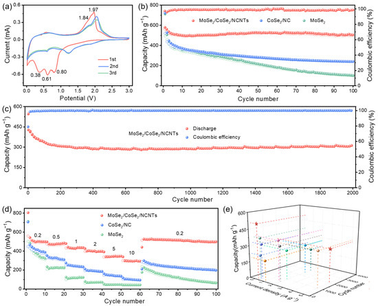
Figure 6.
Electrochemical performances of electrodes in SIBs: (a) CV curves of MoSe2/CoSe2/NCNTs at a scan rate of 0.5 mV s−1 from 0.01 to 3.0 V, (b) cycling performances of MoSe2/CoSe2/NCNTs, CoSe2/NC, and MoSe2 at a current density of 0.2 A g−1, (c) cycling performance of MoSe2/CoSe2/NCNTs at a current density of 5 A g−1, (d) rate performances of MoSe2/CoSe2/NCNTs, CoSe2/NC, and MoSe2 at different current densities of 0.2–10 A g−1, and (e) comparison of performances between MoSe2/CoSe2/NCNTs and the previously reported literature (Pentagram represents this work, others adapted from Refs. [2,3,4,28,29,30,31,32,33]).
Figure 6b and Figure S14a compare the cycling performance of MoSe2/CoSe2/NCNTs, MoSe2/CoSe2/NC, CoSe2/NC, and MoSe2 in SIBs. Apparently, the cycling stability of MoSe2/CoSe2/NCNTs is superior to the other three electrodes. The discharge capacity of MoSe2/CoSe2/NCNTs can be maintained at 505 mAh g−1 after 100 cycles at a current density of 0.2 A g−1. Long cycle life is crucial for the practical application of batteries. Figure 6c exhibits the cycling performance at a high current density of 0.2 A g−1. MoSe2/CoSe2/NCNTs deliver a reversible capacity of 310 mAh g−1 after 2000 cycles. In addition to the outstanding cycle life of MoSe2/CoSe2/NCNTs, what is also attractive is its superior rate capability. When tested at current densities of 0.2, 0.5, 1, 2, 5, and 10 A g−1, MoSe2/CoSe2/NCNTs can deliver capacities of 501, 486, 439, 400, 349, and 296 mAh g−1 (Figure 6d and Figure S14b). Even when the current density returns to 0.2 A g−1 and cycles to 100 cycles, the capacity can still be maintained at 501 mAh g−1, fully recovering to the initial capacity. Such excellent rate capability mainly originated from the built-in electric field at the heterointerface and numerous ion channels provided by the “branches” in the hierarchical branched structure. Moreover, a higher degree of graphitization of NCNTs enhances the overall conductivity of the material and also contributes to the improvement in rate performance. Compared with previous reports, the Na+-ion storage performance of MoSe2/CoSe2/NCNTs can be comparable to that of other MoSe2-based composites (Figure 6e and Table S2) [5,6,7,8,9,34,35,36,37,38].
To explore the origin of excellent Na+-ion storage performance, EIS measurement was employed to investigate the Na+-ion transport rate. Figure 7a and Figure S15a show the Nyquist plots of four electrodes after 100 cycles. The charge transfer resistance of MoSe2/CoSe2/NCNTs is the smallest, followed by MoSe2/CoSe2/NC and CoSe2/NC, while that of MoSe2 is the highest. This indicates that the carbon matrix plays a crucial role in reducing charge transfer resistance, especially highly graphitized carbon materials, which can achieve better results. The fitting results of the straight line in the Nyquist plot also demonstrate that MoSe2/CoSe2/NCNTs have the smallest Warburg impedance coefficient compared to MoSe2/CoSe2/NC, CoSe2/NC, and MoSe2 (Figure 7b and Figure S15b). The diffusion coefficient of Na+ ion is inversely proportional to the Warburg impedance coefficient [39,40], indicating that the diffusion rate of Na+ ion in the bulk phase of MoSe2/CoSe2/NCNTs is the fastest. GITT measurement was employed to grasp in real time the diffusion kinetics of Na+ ions during charging/discharging (Figure 7c and Figure S16a). According to the calculation results, it can be known that the Na+-ion diffusion coefficient of MoSe2/CoSe2/NCNTs fluctuates between 1.1 × 10⁻¹⁰ and 3.5×10⁻⁹ during discharging, while it fluctuates between 1.7 × 10⁻¹⁰ and 2.9 × 10⁻⁹ during charging (Figure 7c and Figure S16a). Compared with MoSe2/CoSe2/NC, CoSe2/NC, and MoSe2, MoSe2/CoSe2/NCNTs deliver higher a Na+-ion diffusion coefficient. Based on all the above results, it can be concluded that MoSe2/CoSe2/NCNTs can undoubtedly serve as feasible anodes in LIBs and SIBs.
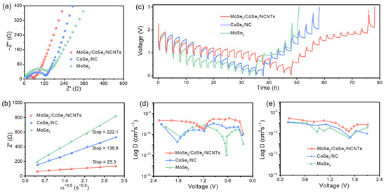
Figure 7.
Kinetics characterization of electrodes in SIBs: (a) Nyquist plots after 100 cycles, (b) the relationship between Zre and ω−1/2, (c) GITT curves at the 5th discharge and charge process, and (d,e) corresponding Na+-ion diffusion coefficients.
4. Conclusions
In summary, we construct a novel hierarchical branched architecture consisting of MoSe2/CoSe2 as the “trunk” and N-doped carbon nanotubes as the “branches”. The built-in electric field at the heterogeneous interface can significantly enhance the diffusion rate of metal ions, promoting the rate performance. In addition, the “branches” in the hierarchical branched architecture, also known as NCNTs, not only provide a large number of channels for the transport of metal ions but also alleviate the huge volume change generated during ion insertion/extraction processes, improving the cycling stability. Furthermore, NCNTs with a higher degree of graphitization also help improve the conductivity of the material. Benefiting from these advantages, MoSe2/CoSe2/NCNTs exhibit high reversible capacity, outstanding cycle cycling stability, and excellent rate capability in both LIBs and SIBs. When the current density reaches 10 A g−1, MoSe2/CoSe2/NCNTs deliver high capacities of 452 mAh g−1 in LIBs and 296 mAh g−1 in SIBs, respectively. Even after 2000 cycles at a current density of 5 A g−1, MoSe2/CoSe2/NCNTs can still maintain capacities of 553 mAh g−1 in LIBs and 310 mAh g−1 in SIBs.
Supplementary Materials
The following supporting information can be downloaded at https://www.mdpi.com/article/10.3390/met14050595/s1. Figure S1. The SEM images of MoSe2. Figure S2. The SEM images of CoSe2/NC. Figure S3. The SEM images of MoSe2/CoSe2/NC. Figure S4. The TEM and HRTEM images of MoSe2/CoSe2/NCNFs. Figure S5. The XRD pattern of MoSe2/CoSe2/NC. Figure S6. The CV curves of samples at a scan rate of 0.5 mV s-1 in LIBs: (a) MoSe2/CoSe2/NC, (b) CoSe2/NC, (c) MoSe2. Figure S7. The charge/discharge profiles of samples at a current density of 0.2 A g-1 in LIBs: (a) MoSe2/CoSe2/NCNFs, (b) MoSe2/CoSe2/NC, (c) CoSe2/NC, (d) MoSe2. Figure S8. Electrochemical performances of MoSe2/CoSe2/NC in LIBs: (a) Cycling performances at 0.2A g-1, (b) Rate performances at 0.2-10 A g-1. Figure S9. (a) Nyquist plots of MoSe2/CoSe2/NC after 100 cycles in LIBs and (b) The relationship between Zre and ω−1/2. Figure S10. E vs. t curves of the MoSe2/CoSe2/NC for a single GITT during discharge process. Figure S11. Electrochemical performances of MoSe2/CoSe2/NC in LIBs: (a) GITT curves at 5th discharge and charge process, (b,c) the corresponding Li+ diffusion coefficient at 5th discharge and charge process. Figure S12. The CV curves of samples at a scan rate of 0.5 mV s-1 in SIBs: (a) MoSe2/CoSe2/NC, (b) CoSe2/NC, (c) MoSe2. Figure S13. The charge/discharge profiles of samples at a current density of 0.2 A g-1 in SIBs: (a) MoSe2/CoSe2/NCNFs, (b) MoSe2/CoSe2/NC, (c) CoSe2/NC, (d) MoSe2. Figure S14. Electrochemical performances of MoSe2/CoSe2/NC in SIBs: (a) Cycling performances at 0.2 A g−1, (b) Rate performances at 0.2–10 A g−1. Figure S15. (a) Nyquist plots of MoSe2/CoSe2/NC after 100 cycles in SIBs and (b) The relationship between Zre and ω−1/2. Figure S16. Electrochemical performances of MoSe2/CoSe2/NC in SIBs: (a) GITT curves at 5th discharge and charge process, (b,c) the corresponding Li+ diffusion coefficient at 5th discharge and charge process. Table S1. Comparison of electrochemical performance in LIBs between MoSe2/CoSe2/NC and previously reported literature. Table S2. Comparison of electrochemical performance in SIBs between MoSe2/CoSe2/NC and previously reported literature. Refs. [41,42,43,44] are cited in the supplementary materials.
Author Contributions
Conceptualization, H.K.; methodology, H.K.; formal analysis, Y.W.; validation, S.C.; investigation, X.C. and N.M.; data curation, J.Y. and R.C.; writing—original draft preparation, H.K.; writing—review and editing, H.K.; supervision, H.K.; project administration, H.K. All authors have read and agreed to the published version of the manuscript.
Funding
This research was funded by the National Natural Science Foundation of China (No. 22302072), the Natural Science Foundation of Xiamen, China (3502Z20227029), the Scientific Research Funds of Huaqiao University (21BS115), and the Natural Science Foundation of Fujian Province-STS Project (2023T31020012).
Data Availability Statement
The original contributions presented in the study are included in the article, further inquiries can be directed to the corresponding author.
Conflicts of Interest
The authors declare no conflicts of interest.
References
- Shi, Y.; Zhou, X.; Yu, G. Material and structural design of novel binder systems for high-energy, high-power lithium-ion batteries. Acc. Chem. Res. 2017, 50, 2642–2652. [Google Scholar] [CrossRef] [PubMed]
- Ni, X.; Cui, Z.; Luo, H.; Chen, H.; Liu, C.; Wu, Q.; Ju, A. Hollow multi-nanochannel carbon nanofibers@MoSe2 nanosheets composite as flexible anodes for high performance lithium-ion batteries. Chem. Eng. J. 2021, 404, 126249. [Google Scholar] [CrossRef]
- Chen, J.; Luo, Y.; Zhang, W.; Qiao, Y.; Cao, X.; Xie, X.; Zhou, H.; Pan, A.; Liang, S. Tuning interface bridging between MoSe2 and three-dimensional carbon framework by incorporation of MoC intermediate to boost lithium storage capability. Nano-Micro Lett. 2020, 12, 171. [Google Scholar] [CrossRef] [PubMed]
- Wang, S.; Si, Y.; Wan, P.; Zhu, S.; Chu, W.; Yu, Z. MoSe2 nanoflowers grown on 3D carbon network as an advanced anode for lithium ion batteries. Mater. Lett. 2022, 310, 131487. [Google Scholar] [CrossRef]
- Wang, W.; Hu, L.; Li, L.; Liu, C.; Liu, X.; Wang, H.; Zhai, G. Constructing a rapid ion and electron migration channels in MoSe2/SnSe2@C 2D heterostructures for high-efficiency sodium-ion half/full batteries. Electrochim. Acta 2023, 449, 142239. [Google Scholar] [CrossRef]
- Xie, X.; Huang, K.; Wu, X.; Wu, N.; Xu, Y.; Zhang, S.; Zhang, C. Binding hierarchical MoSe2 on MOF-derived N-doped carbon dodecahedron for fast and durable sodium-ion storage. Carbon 2020, 169, 1–8. [Google Scholar] [CrossRef]
- He, H.; Zhang, H.; Huang, D.; Kuang, W.; Li, X.; Hao, J.; Guo, Z.; Zhang, C. Harnessing plasma-assisted doping engineering to stabilize metallic phase MoSe2 for fast and durable sodium-ion storage. Adv. Mater. 2022, 34, 2200397. [Google Scholar] [CrossRef] [PubMed]
- Yang, Y.; Wang, F.; Chen, Y.; Chen, C.; Zhang, S.; Yu, Z.; Au, C.; Yin, S.; Qiu, R. Building a PEG-C@MoSe2@CNT heterostructure via in-situ selenidation as highly reversible anodes for Na+ batteries. Sci. China Chem. 2023, 66, 475–491. [Google Scholar] [CrossRef]
- Zhao, X.; Zhao, Y.; Huang, B.; Cai, W.; Sui, J.; Yang, Z.; Wang, H.-E. MoSe2 nanoplatelets with enriched active edge sites for superior sodium-ion storage and enhanced alkaline hydrogen evolution activity. Chem. Eng. J. 2020, 382, 123047. [Google Scholar] [CrossRef]
- Qin, F.; Hu, H.; Jiang, Y.; Zhang, K.; Fang, Z.; Lai, Y.; Li, J. Mesoporous MoSe2/C composite as anode material for sodium/lithium ion batteries. J. Electroanal. Chem. 2018, 823, 67–72. [Google Scholar] [CrossRef]
- Yang, J.; Luo, J.; Kuang, Y.; He, Y.; Wen, P.; Xiong, L.; Wang, X.; Yang, Z. Exploring the efficient Na/K storage mechanism and vacancy defect-boosted li+ diffusion based on VSe2/MoSe2 heterostructure engineering. ACS Appl. Mater. Inter. 2020, 13, 2072–2080. [Google Scholar] [CrossRef] [PubMed]
- Zheng, Y.; Zhou, T.; Zhang, C.; Mao, J.; Liu, H.; Guo, Z. Boosted charge transfer in SnS/SnO2 heterostructures: Toward high rate capability for sodium-ion batteries. Angew. Chem. Int. Edit. 2016, 55, 3408–3413. [Google Scholar] [CrossRef]
- Fang, G.; Wang, Q.; Zhou, J.; Lei, Y.; Chen, Z.; Wang, Z.; Pan, A.; Liang, S. Metal organic framework-templated synthesis of bimetallic selenides with rich phase boundaries for sodium-ion storage and oxygen evolution reaction. Acs Nano. 2019, 13, 5635–5645. [Google Scholar] [CrossRef]
- Hong, X.; Kim, J.; Shi, S.; Zhang, Y.; Jin, C.; Sun, Y.; Tongay, S.; Wu, J.; Zhang, Y.; Wang, F. Ultrafast charge transfer in atomically thin MoS2/WS2 heterostructures. Nat. Nanotech. 2014, 9, 682–686. [Google Scholar] [CrossRef]
- Nishitani, J.; Yu, K.; Walukiewicz, W. Charge transfer and mobility enhancement at CdO/SnTe heterointerfaces. Appl. Phys. Lett. 2014, 105, 132103. [Google Scholar] [CrossRef]
- Kong, H.; Cui, W.; Yan, C.; Kong, Y.; Lv, C.; Chen, G. Interface engineering on cobalt selenide composites enables superior alkali-ion storage. Chem. Eng. J. 2021, 419, 129490. [Google Scholar] [CrossRef]
- Su, Q.; Cao, X.; Yu, T.; Kong, X.; Wang, Y.; Chen, J.; Lin, J.; Xie, X.; Liang, S.; Pan, A. Binding MoSe2 with dual protection carbon for high-performance sodium storage. J. Mater. Chem. A 2019, 7, 22871–22878. [Google Scholar] [CrossRef]
- Niu, F.; Yang, J.; Wang, N.; Zhang, D.; Fan, W.; Yang, J.; Qian, Y. MoSe2-covered N, P-doped carbon nanosheets as a long-life and high-rate anode material for sodium-ion batteries. Adv. Funct. Mater. 2017, 27, 1700522. [Google Scholar] [CrossRef]
- Guo, K.; Xi, B.; Wei, R.; Li, H.; Feng, J.; Xiong, S. Hierarchical microcables constructed by CoP@C⊂carbon framework intertwined with carbon nanotubes for efficient lithium storage. Adv. Energy Mater. 2020, 10, 1902913. [Google Scholar] [CrossRef]
- Yang, J.; Gao, H.; Men, S.; Shi, Z.; Lin, Z.; Kang, X.; Chen, S. CoSe2 nanoparticles encapsulated by N-doped carbon framework intertwined with carbon nanotubes: High-performance dual-role anode materials for both Li-and Na-ion batteries. Adv. Sci. 2018, 5, 1800763. [Google Scholar] [CrossRef]
- Pang, Y.; Chen, S.; Xiao, C.; Ma, S.; Ding, S. MOF derived CoO-NCNTs two-dimensional networks for durable lithium and sodium storage. J. Mater. Chem. A 2019, 7, 4126–4133. [Google Scholar] [CrossRef]
- Li, T.; Li, S.; Liu, Q.; Yin, J.; Sun, D.; Zhang, M.; Xu, L.; Tang, Y.; Zhang, Y. Immobilization of Ni3Co nanoparticles into N-doped carbon nanotube/nanofiber integrated hierarchically branched architectures toward efficient overall water splitting. Adv. Sci. 2020, 7, 1902371. [Google Scholar] [CrossRef] [PubMed]
- Miao, W.; Zhang, Y.; Li, H.; Zhang, Z.; Li, L.; Yu, Z.; Zhang, W. ZIF-8/ZIF-67-derived 3D amorphous carbon-encapsulated CoS/NCNTs supported on CoS-coated carbon nanofibers as an advanced potassium-ion battery anode. J. Mater. Chem. A 2019, 7, 5504–5512. [Google Scholar] [CrossRef]
- Patil, S.; Chodankar, N.; Hwang, S.; Shinde, P.; Raju, G.; Ranjith, K.; Huh, Y.; Han, Y. Co-metal–organic framework derived CoSe2@MoSe2 core–shell structure on carbon cloth as an efficient bifunctional catalyst for overall water splitting. Chem. Eng. J. 2022, 429, 132379. [Google Scholar] [CrossRef]
- Tang, X.; Zhang, J.; Mei, B.; Zhang, X.; Liu, Y.; Wang, J.; Li, W. Synthesis of hollow CoSe2/MoSe2 nanospheres for efficient hydrazine-assisted hydrogen evolution. Chem. Eng. J. 2021, 404, 126529. [Google Scholar] [CrossRef]
- Li, H.; Qian, X.; Zhu, C.; Jiang, X.; Shao, L.; Hou, L. Template synthesis of CoSe2/Co3Se4 nanotubes: Tuning of their crystal structures for photovoltaics and hydrogen evolution in alkaline medium. J. Mater. Chem. A 2017, 5, 4513–4526. [Google Scholar] [CrossRef]
- Jin, R.; Cui, Y.; Wang, Q.; Li, G. Facile fabrication of CNTs@C@ MoSe2@Se hybrids with amorphous structure for high performance anode in lithium-ion batteries. J. Colloid Inter. Sci. 2017, 508, 435–442. [Google Scholar] [CrossRef] [PubMed]
- Liu, Y.; Cao, J.; Cai, J.; Chen, M.; Wang, L.; Huang, X.; Liao, S.; Min, Y. Flower-like MoSe2@N-doped carbon sub-nanoclusters regulated by MoO3 hexagonal prism as advanced anode for lithium-ion battery. J. Alloys Compd. 2021, 865, 158276. [Google Scholar] [CrossRef]
- Li, N.; Zhou, Q.; Lin, J.; Lu, Y.; Hou, Z.; Qian, Y. One-pot synthesis of uniform MoSe2 nanoparticles as high performance anode materials for lithium/sodium ion batteries. J. Alloys Compd. 2022, 922, 166306. [Google Scholar] [CrossRef]
- Cu, Q.; Shang, C.; Zhou, G.; Wang, X. Freestanding MoSe2 nanoflowers for superior Li/Na storage properties. Tungsten 2024, 6, 238–247. [Google Scholar] [CrossRef]
- Zhang, K.; Jiang, X.; Zeng, M.; Jing, B. Hydrothermal synthesis of three-dimensional hydrangea-like MoSe2@N-doped carbon anode material for high performance lithium ion batteries. J. Electroanal. Chem. 2020, 879, 114818. [Google Scholar] [CrossRef]
- Wu, Y.; Liu, W. Few-layered MoSe2 ultrathin nanosheets as anode materials for lithium ion batteries. J. Alloys Compd. 2020, 813, 152074. [Google Scholar] [CrossRef]
- Qin, Z.; Liu, X.; Huang, Z.; Sun, R.; Li, Z.; Fan, H.; Lu, S. Electrochemical and pseudocapacitive analysis of rod-like MoO2@MoSe2@NC heterostructures for high-performance lithium ion batteries. Acta Metall. Sin. 2021, 34, 425–434. [Google Scholar] [CrossRef]
- Xu, E.; Zhang, Y.; Wang, H.; Zhu, Z.; Quan, J.; Chang, Y.; Li, P.; Yu, D.; Jiang, Y. Ultrafast kinetics net electrode assembled via MoSe2/MXene heterojunction for high-performance sodium-ion batteries. Chem. Eng. J. 2019, 382, 123839. [Google Scholar] [CrossRef]
- Chong, S.; Wei, X.; Wu, Y.; Sun, L.; Shu, C.; Lu, Q.; Hu, Y.; Cao, G.; Huang, W. Expanded MoSe2 nanosheets vertically bonded on reduced graphene oxide for sodium and potassium-ion storage. ACS Appl. Mater. Interfaces 2021, 13, 13158–13169. [Google Scholar] [CrossRef] [PubMed]
- Xu, Y.; Liu, X.; Su, H.; Jiang, S.; Zhang, J.; Li, D. Hierarchical bimetallic selenides CoSe2–MoSe2/rGO for sodium/potassium-ion batteries anode: Insights into the intercalation and conversion mechanism. Energy Environ. Mater. 2022, 5, 627–636. [Google Scholar] [CrossRef]
- Seon, Y.; Kang, Y.; Cho, J. One-dimensional porous nanostructure composed of few-layered MoSe2 nanosheets and highly densified-entangled-N-doped CNTs as anodes for Na ion batteries. Chem. Eng. J. 2021, 425, 129051. [Google Scholar] [CrossRef]
- Chen, S.; Shi, Y.; Ma, L.; Li, N.; Wang, Z.; Wu, M. Selenide-based anodes for advanced sodium-ion batteries. Energy Environ. Sci. 2023, 16, 1074–1096. [Google Scholar]
- Kong, H.; Ou, J.; Chen, L.; Sun, W.; Fu, F.; Zhang, H.; Chen, H. Interlayer engineering in V6O13 nanobelts toward superior Mg-ion storage. Inorg. Chem. Front. 2023, 10, 544–551. [Google Scholar] [CrossRef]
- Kong, H.; Lv, C.; Wu, Y.; Yan, C.; Chen, G. Integration of cobalt selenide nanocrystals with interlayer expanded 3D Se/N Co-doped carbon networks for superior sodium-ion storage. J. Energy Chem. 2021, 55, 169–175. [Google Scholar] [CrossRef]
- Wang, K.; Zhou, Y.; Cheng, L.; Li, D.; Hu, Z.; Chen, S.; Wu, C.; Song, L.; Ge, B. Engineering phase transition from 2H to 1T in MoSe2 by W cluster doping toward lithium-ion battery. Inorg. Chem. 2023, 62, 21257–21264. [Google Scholar] [CrossRef] [PubMed]
- Li, J.; Sun, L.; Li, H.; Zhang, Y.; Yang, Y.; Luo, Y.; Qin, Y.; Wang, J. MoSe2 nanosheets anchored on carbon nanofibers as advanced anodes for lithium-ion batteries. Electrochim. Acta. 2023, 426, 140743. [Google Scholar]
- Yang, Y.; Wang, F.; Bian, M.; Chen, Y.; Zhang, S.; Yu, Z.; Au, C.; Yin, S.; Qiu, R. Design and synthesis of C@MoSe2@NMWCNT heterostructure as anode material for Na+ Batteries via Mo-Based organic complexes. Electrochimica Acta 2023, 461, 142598. [Google Scholar] [CrossRef]
- Xu, J.; Wu, D.; Hao, J.; Shen, J.; Liu, Q.; Zhang, P.; Jiang, F. Advanced cathode materials for sodium-ion batteries. Adv. Mater. 2023, 35, 2203087. [Google Scholar]

Disclaimer/Publisher’s Note: The statements, opinions and data contained in all publications are solely those of the individual author(s) and contributor(s) and not of MDPI and/or the editor(s). MDPI and/or the editor(s) disclaim responsibility for any injury to people or property resulting from any ideas, methods, instructions or products referred to in the content. |
© 2024 by the authors. Licensee MDPI, Basel, Switzerland. This article is an open access article distributed under the terms and conditions of the Creative Commons Attribution (CC BY) license (https://creativecommons.org/licenses/by/4.0/).