Abstract
The laser drilling of carbon steel is always suffered from the formation of slag, the presence of cutting burrs, the generation of a significant quantity of spatter, and the incomplete penetration of the substrate. In order to avoid these defects formed during the laser drilling of carbon steel, the COMSOL multi-physics simulation method was used to model and optimize the laser drilling process. Considering the splash evolution of the material during the complex drilling process, the transient evolution of the temperature field, the flow of the molten fluid, the geometrical changes, and the absorption of the laser energy during the laser drilling process were investigated. The simulated borehole dimensions are consistent with the experimental results. The process parameters have a great influence on the fluid flow pattern and material slag splashing. The laser power has a significant effect on the laser processing compared with the process parameters. With the increase in laser power and the decrease in laser heat source radius, the time required for perforation is reduced, the flow of melt is accelerated, the perforation efficiency is increased, and the hole wall is smoother, but the degree of spattering is greater. The optimized process parameters were obtained: laser heat source radius of 0.3 mm, laser power of 3000 W. These findings can help reduce the machining defects in carbon steel with excellent mechanical properties by optimizing the laser drilling processing parameters.
1. Introduction
Laser technology, renowned for its high energy density and focused beam characteristics, has emerged as a crucial tool in material processing and manufacturing processes [1,2,3], such as laser drilling, a technique that has gained significant attention. Carbon steel, a key industrial material, finds extensive use in various manufacturing sectors. However, the process of laser drilling carbon steel frequently encounters challenges such as the formation of slag, the presence of cutting burrs, the generation of a significant quantity of spatter, and the incomplete penetration of the substrate [4].
Due to the intricacies associated with experimental procedures and the expenses incurred, Voisey, K.T et al. [5,6,7,8] initially introduced the concept of numerical simulation for laser material processing which is consistently employed to mitigate the frequency of repetition and minimize the occurrence of errors during experimental tests. It also diminishes the reliance on experimental studies, thereby facilitating the efficient optimization of drilling processes. There are different kinds of numerical models applied to laser drilling of carbon steel processes [9,10,11]. However, the splash evolution of the material during the complex drilling process, despite being a crucial phenomenon, is always neglected. Fortunately, the simulation method can effectively address these limitations and accurately simulate the physical splashing phenomenon. The laser drilling of carbon steel involves various processes, such as the propagation and absorption of laser, heat transfer among the gas, laser and the materials, material phase transformation from solid to liquid or from liquid to solid, fluid flow behavior, and structural deformation. Dada, M et al. [12] used multi-physics simulation techniques to model the metal heating process with the main purpose of optimizing the parameters. Results showed an accuracy of the subsequent thermal variations within the material. Parekh et al. [13] established two-dimensional models for the laser processing using a multi-physics simulation method and investigated the influence of laser process parameters on the temperature field. Results showed that, compared with the scanning speed and spot diameter, the power had a significant effect. From the above analyses, it can be concluded that the multi-physics simulation models can accurately predict heat and temperature transfer behaviors in laser processing and, specifically, describe the variations of the molten pool during the additive manufacturing process. The multi-physics simulation method has played an important role in the study of the properties of complex materials in laser forming processes. However, most investigations are mainly focused on the cladding effect on the matrix and the cladding efficiency between the cladding layers.
For the laser drilling processing, numerical simulation methods can be carried out by using the two-dimensional heat conduction principle and multi-physics models. The simulation results can visualize the changes in the temperature profile with time, the distribution of laser energy, and the temperature gradient. Moreover, three-dimensional models have also been generated to study the coaxial powder flow process during the laser drilling metal processing. There are many factors affecting the surface smoothness and properties of the materials, such as the position of the substrate under the melt pool, the temperature field change due to the heat transfer among the laser, gas, and materials, the temperature gradient changed and influenced by the energy [14,15,16]. From the above, it emerges that the transient simulation of the laser forming processing can be performed using the finite element, level set, dynamics, and other approaches to study the mechanism of melt injection and slag sputtering in laser drilling and to improve the transient model for detailed analysis. However, how to avoid efficiently the defects formed during the laser drilling of carbon steel is still little explored. In particular, how to accurately model and optimize the laser drilling process using the COMSOL multi-physics simulation method needs to be further investigated.
In this study, a simulation of laser processing drilling was conducted to minimize slag and splash formation. The temperature distribution of the carbon steel during laser processing was investigated by varying the processing parameters and the heat transfer mechanisms during laser drilling, and the impact of the temperature distribution and various laser processing parameters on the laser drilling process was also assessed [17,18]. This work can help avoid excessive slag and splash in practical production scenarios, providing valuable guidance on the application of laser drilling processing techniques.
2. Numerical Simulation
2.1. Mathematical Model
In order to conduct a detailed analysis of the drilling processing, the improved transient model was performed using the continuity equations, Navier–Stokes equations, level set equations, and energy conservation equations to study the mechanism of melt injection and slag sputtering. Table 1 shows the parameters required for the numerical simulation of carbon steel.

Table 1.
Carbon steel properties for the stimulation adapted from Ref. [19].
When the materials have absorbed enough energy, the material undergoes melting, vaporization, and melt injection until small holes are formed due to the laser energy. A continuity equation, Equation (1), was used for both solid and liquid phases:
where is the mass flux, and are the density of liquid and solid, respectively, δ is the delta function, is the heat transfer coefficient, and µ is the dynamic viscosity.
The laser heating process produces evaporation, which is mainly affected by mass flux and calculated using temperature and saturation pressure. The can be calculated from Equation (3) [20]:
where is the recoil pressure and T is the temperature.
The original Navier–Stokes equations can only be solved in the liquid and solid phases, ignoring the gas–liquid interface forces, and cannot accurately simulate the dynamic process of the melt pool. In this work, the gas phase was incorporated into the model through the following modification [21,22,23]:
where M is the interface force, including the recoil pressure, surface tension, and Marangoni force, p is the pressure of the fluid, I is the unit matrix, is the expansion coefficient, and and K are the reference temperature and isotropic permeability, respectively.
where σ is the surface tension coefficient, k is the radius of the curvature, precoil is the recoil pressure equal to 0.54 , and n and T are normal tangential unit vectors.
Through the improved model, the transfer equation of the level set is modified by using source terms. We get the following equation:
where u is the velocity, is the mass flux, and are two level set parameters, and t is time.
The phase transformation from solid to liquid state of carbon steel during the laser drilling processing is closely related to heat transfer and temperature distribution. Laser energy is applied to the surface of the carbon steel, the temperature of the materials increases, causing localized melting into a molten pool, and then decreases due to the heat transferred to the surrounding area. Therefore, heat exchange in terms of heat conduction, convection, and radiation occurs in the flow of the melt and the surrounding environment. The heat transfer equation in the numerical simulation can be established using Fourier’s equation and the law of conservation of energy:
where is the laser irradiation heat flux, and are the evaporative heat and flow rate, respectively, Cp presents the specific heat capacity, and λ is the thermal conductivity.
In the simulation of laser punching, the laser pulse heat resources can be described through Equation (8) [24,25], while a gaussian energy distribution is loaded as a surface heat source:
where is the heat flux density measured at the distance x, is the heat flux density of the heat source, and δ is the standard deviation of the heat source. The laser heat source is a gaussian heat source and the laser heat flux needs to be calculated.
Assuming symmetry of the perforation and smooth melt flow during the laser drilling processing, two-dimensional geometric models were established for the transient numerical simulation. A two-phase flow model and the level set numerical simulation method were adopted to simulate the laser drilling processing. Firstly, the two-dimensional model of a two-phase flow was divided into two parts: the upper part was the gas phase and the bottom part was the carbon steel material, transformed into the liquid phase after laser perforation. The initial temperature of the material was 300 k. The model consisted of a two-phase flow and a phase transition, dynamic surface tension, Marangoni forces, convection, hydrostatic pressure, and viscous forces. The experiments were conducted after the simulation of the related process optimization.
2.2. Experimental Method
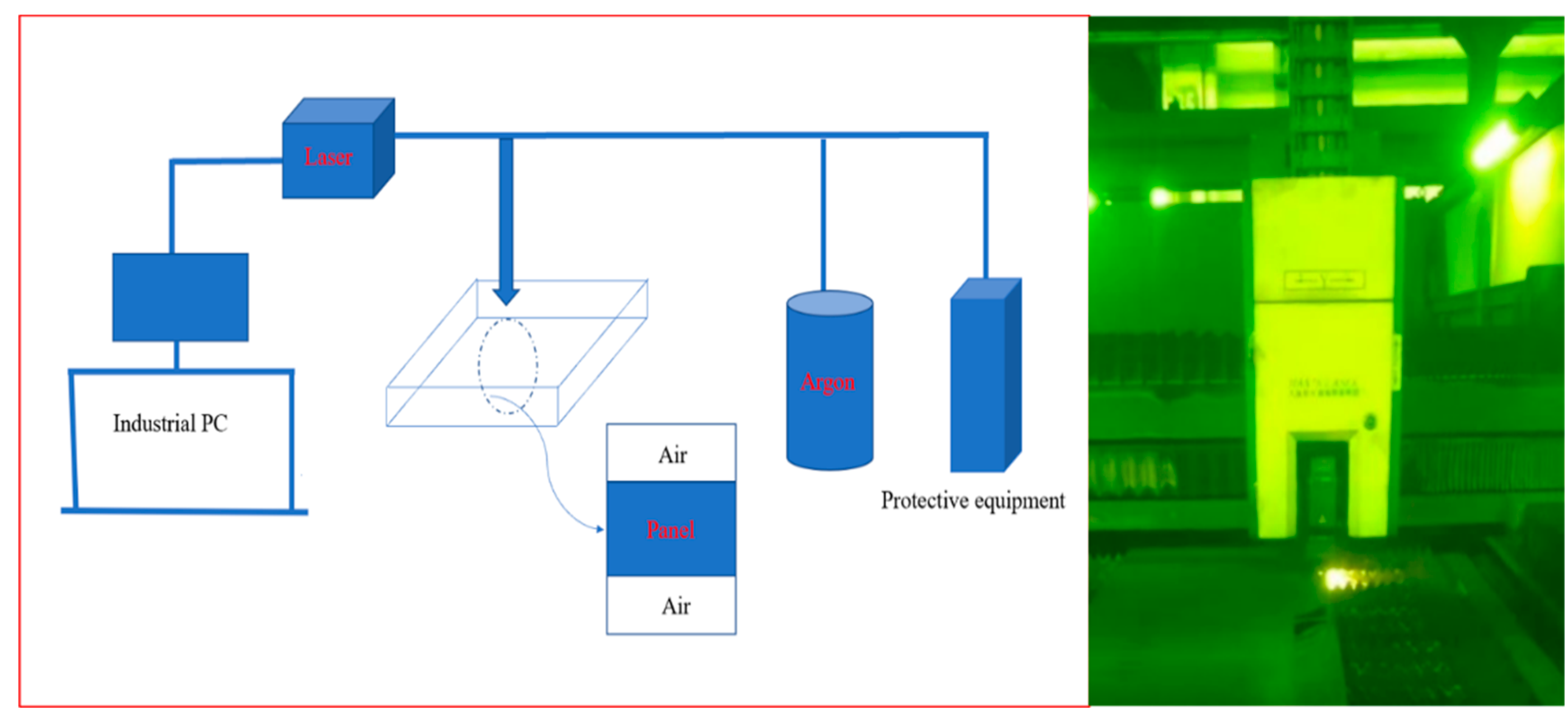
A high-power fiber laser cutting machine (G4020MF, Shenzhen, China) was used for the experimental procedure, the equipment come from form Han’s lasers, as shown in Figure 1. When the laser was used to drill the plate, the drilling effectiveness, melting condition, and splash magnitude were monitored simultaneously. The plate material was steel, and its composition, assessed using a direct reading spectrometer, is displayed in Table 2.
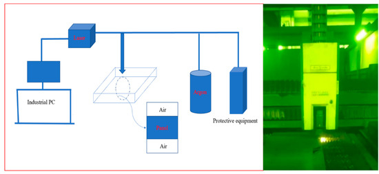
Figure 1.
A photo of the G4020MF fiber laser cutting machine and the machining head.
Table 2.
Chemical composition test results of carbon steel.
Moreover, a beam intensity that follows a gaussian distribution and a pulse-shaped time distribution were introduced. The cutting process is safeguarded by inert gas, thus guaranteeing precision in cutting operations. In comparison to traditional cutting methods, the fiber laser cutting machine exhibits numerous machining advantages. It possesses capabilities such as automatic edge patrol and automatic break point return. With regard to cutting and drilling operations, it excels in tasks such as small hole drilling, rapid cutting of thick plates, as well as burr-free cutting technology for aluminum alloys. The equipment is suitable for processing various metal materials including carbon steel, stainless steel, alloy materials, and aluminum. This particular experiment primarily focused on the pre-perforation step prior to cutting which can directly impact the cutting efficiency of the plate.
During the industrial production, the laser drilling of plates with a thickness of 8 mm and 12 mm tend to produce a lot of slag and splash, and even leads to repeated perforation, which affects the cutting efficiency significantly. The thicker the plate, the more numerous the problems related to perforation. In order to prevent such occurrences, carbon steel plates with a thickness of 8 mm were selected for drilling in the text experiment. The perforation method for this experiment was pulsed perforation, which uses a pulsed laser with peak power to melt or vaporize a small amount of material. Each pulsed laser produces only small jets of particles which dig deeper and deeper into the material, thus the perforation of thick plates takes a few seconds. As soon as the perforation was completed, cutting was carried out with oxygen instead of an auxiliary gas to produce a smaller hole size.
3. Results and Discussions
Verification of the Simulation Results
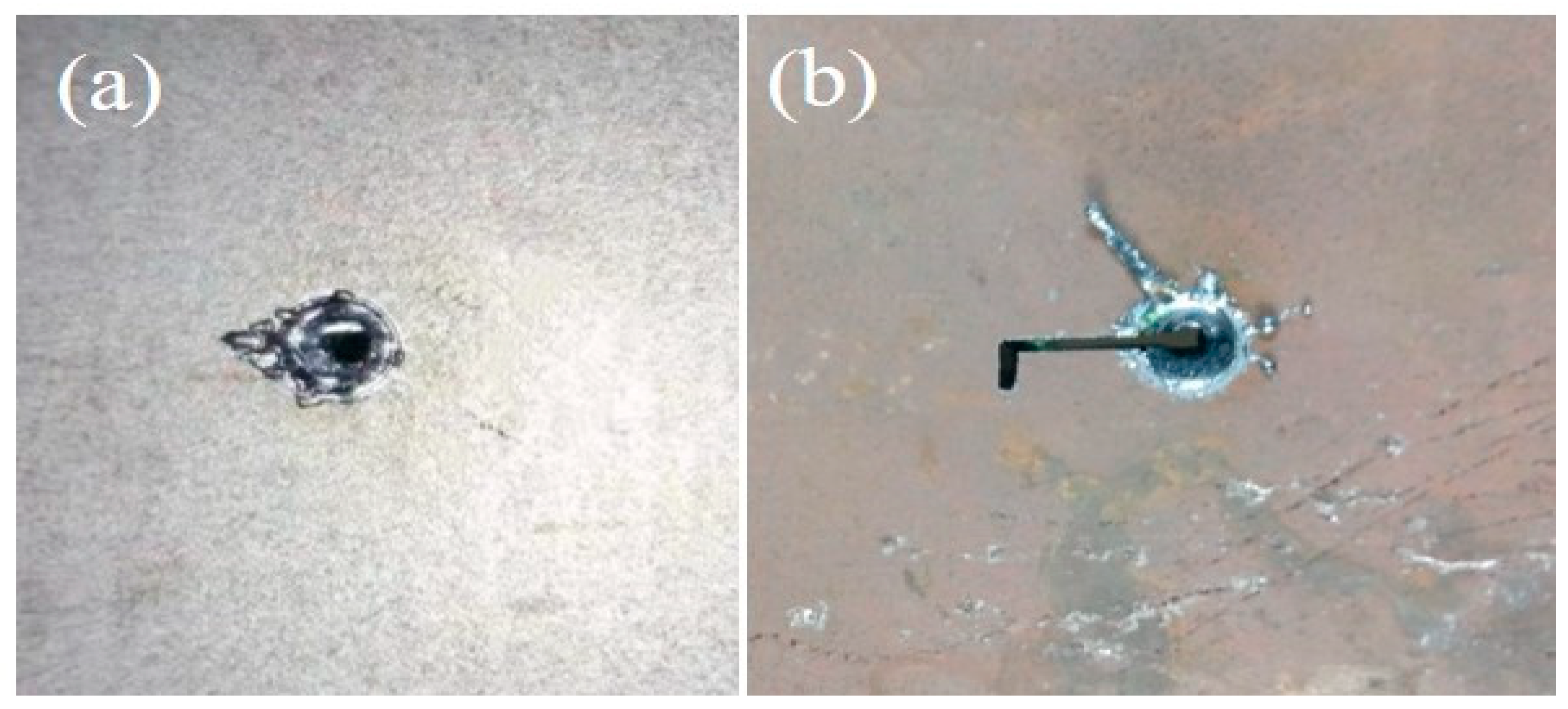
The effect of actual laser drilling of carbon steel at different laser powers is shown in Figure 2. When the laser power was too low, the molten liquid did not reach the complete melting state, as shown in Figure 2a, and, when the laser power was too high, the molten liquid produced a lot of slag splashing, as shown in Figure 2b. It can be safely concluded that, when the parameters are not ideal, the perforation process fails and generates a lot of slag, splashing, and the melt solidifies directly in the hole, with the failure of perforation leading to slow productivity. The quality of the perforation is affected by the laser power, focus bias, and perforation time. Too little laser power will not penetrate, too much laser power will produce a lot of spatter slag resulting in the suspension of the piercing process; therefore, it is very important to choose a reasonable piercing process.
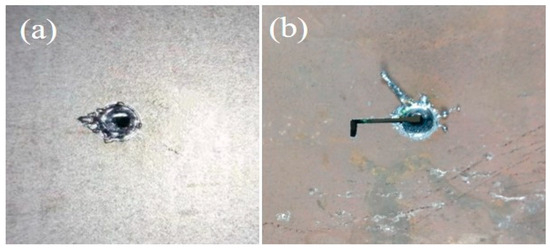
Figure 2.
The effect of actual laser drilling of carbon steel at different laser powers: (a) the laser power is too low, and the molten liquid does not reach the complete melting state; (b) the laser power is too high, and the molten liquid produces a lot of slag splashing.
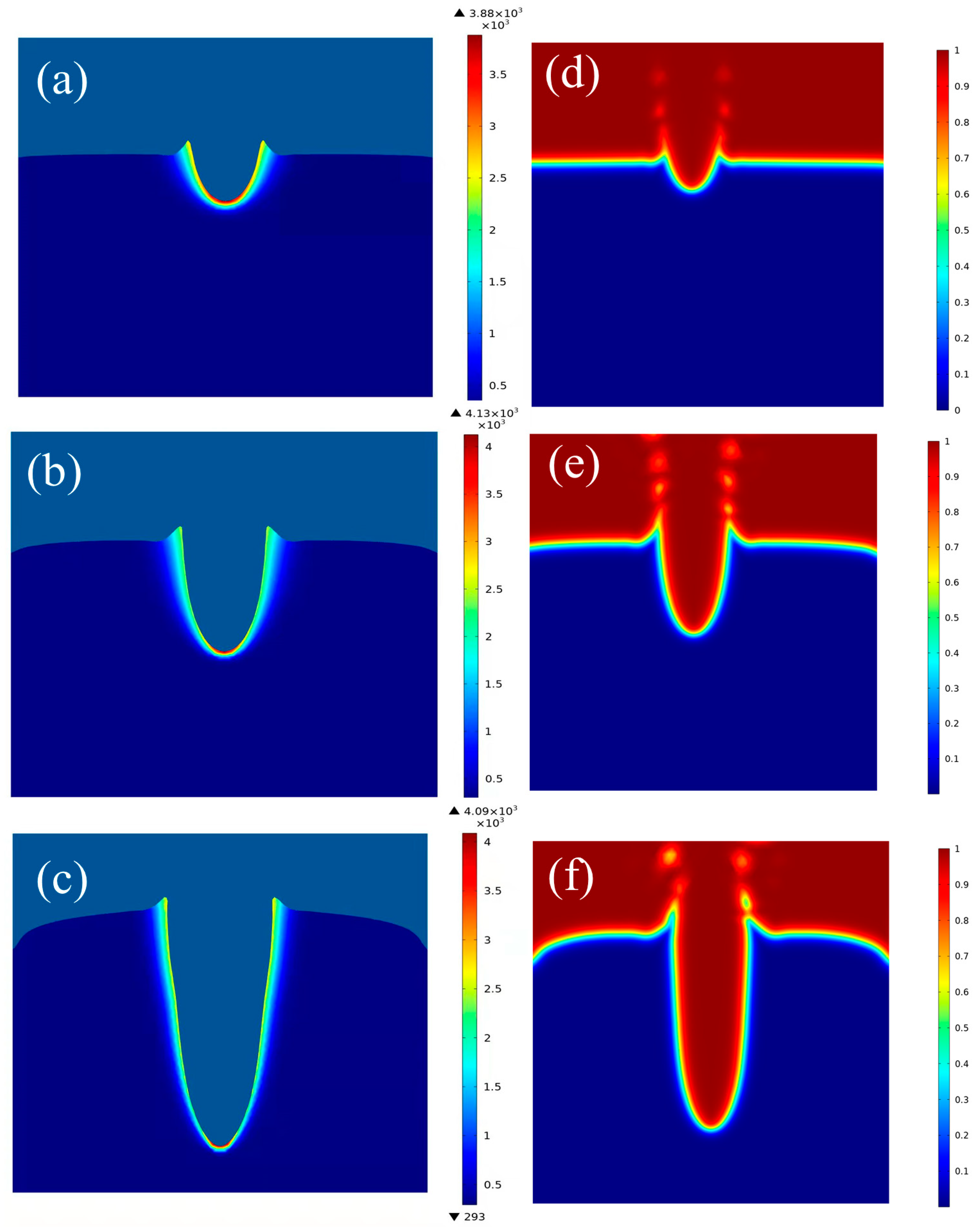
Based on the above established models, the molten pool evolution and droplet ejection process during hole formation were numerically simulated. Laser drilling was conducted under different laser powers of 1200 W, 2000 W, 3000 W, and 3500 W. The variation of the hole and splash characteristics was numerically simulated under the same laser processing parameters, as shown in Figure 3. It can be observed that, during the period ranging from 10 ms to 30 ms, a molten pool with a bowl-like shape and cleanly defined edges emerged. Additionally, smaller metal droplets were ejected perpendicularly to the concave surface, aligned with the direction of the incoming laser beam.

Figure 3.
Temperature distribution within the field at distinct time intervals: (a) at 30 ms, (b) at 80ms, and (c) near the perforation point under a constant power laser. (d–f) Corresponding flow field under the same conditions.
During the laser drilling process, protrusions emerged, the convex peaks appearing within and adjacent to the plane machining area, accompanied by the ejection of larger droplets. The quantity of molten liquid is dictated by the intensity of the laser power and the focal offset. During the simulation, it was observed that, as holes were being formed, the molten liquid commenced splashing. Subsequently, as the laser continued to operate, the holes progressively deepened, and the ejection of molten material persisted. At 60 ms, the formation of holes became evident, and a relatively significant degree of splashing became observable. The injection of molten material persisted throughout the duration of the laser illumination during the drilling processing.
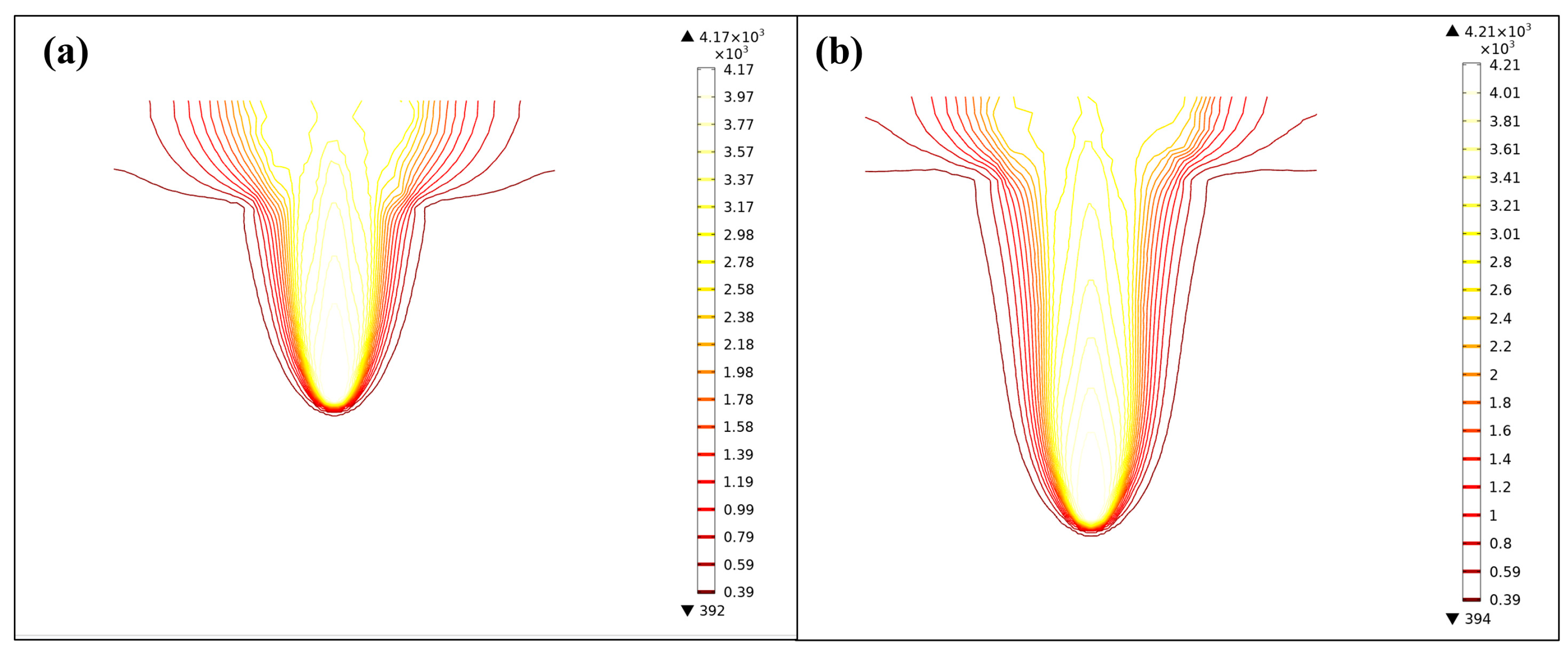
By utilizing the fluid volume method, the phase volume fraction variations and the temperature profiles during the laser drilling process can be clearly observed, as shown in Figure 4. It can be observed that the heating interface varied with time. The laser action was most pronounced at the bottom, resulting in the highest temperature at the bottom surface of the materials due to its direct contact with the laser beam. Figure 4 illustrates the isothermal line distribution during laser drilling, exhibiting a significant temperature gradient distribution. This numerical simulation effectively allows for the observation of numerical value variations throughout the laser drilling process, enabling more rational adjustments to technological parameters. Notably, the simulation results were consistent with the experimental result, indicating that the above models are reliable for guiding industrial production applications.
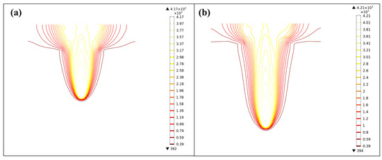
Figure 4.
Isothermal line distribution during laser drilling: (a) at 30ms and (b) near the perforation point under a constant power laser.
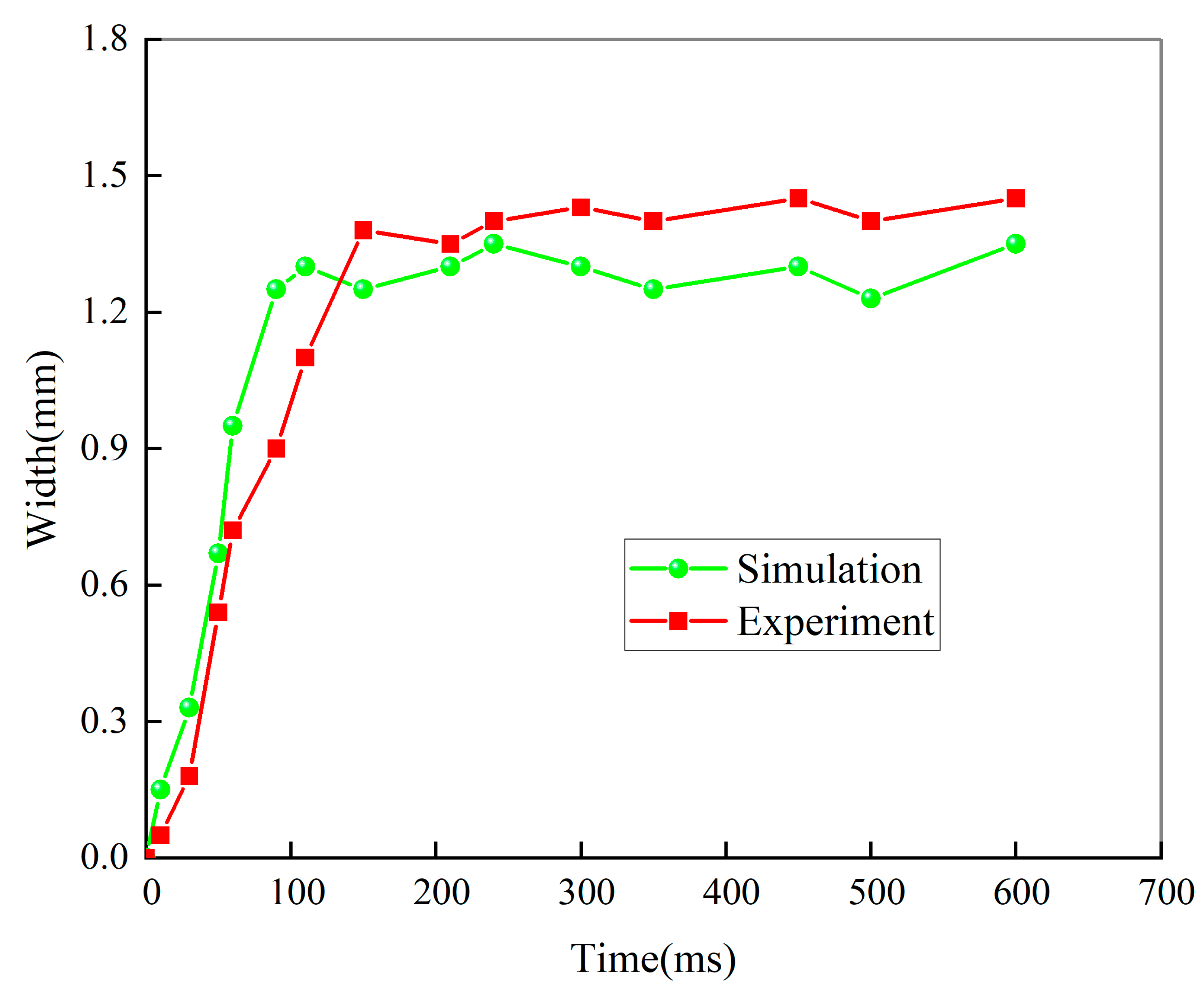
The variation of the simulated molten pool width changed with time, as shown in Figure 5. It can be seen that the simulated width of the molten pool formed in the carbon steel was about 1.4 mm. Moreover, the liquid velocity reached up to 10.38 m·s−1. Splashing occurs when the momentum of a liquid exceeds the viscosity and surface tension of the molten material. Under the same processing speed of 2.5 m·s−1, the variations in the simulated width were similar to those exhibited by the experiment monitor, meaning that the simulation results were consistent with the estimation results, as shown in Figure 5.
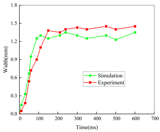
Figure 5.
The width of the molten pool changed with time in the laser drilling process.
The comparison between the simulation and experimental data in Figure 5 still displays a little deviation. This can be attributed to the deviation of the artificial measurement value, deviation of focus bias in experimental process, and environmental factors. However, the deviation was so small that it could be neglected. In order to obtain appropriate parameters, the process parameters were adjusted based on the simulation results and experimental test, as shown in Table 3. After adjusting the parameters, the expected effect was obtained, i.e., small holes were obtained.
Table 3.
Basic technological parameters of the laser drilling process.
During laser perforation, the laser-irradiated material was rapidly heated, melted, evaporated, and expanded, generating a very high recoil pressure on the molten pool which removed the molten material by melt recoil. Then, the ejected metal jet, crushed by the evaporation of the metal and broken into tiny droplets, was passed through the laser to form a droplet splash. High-power laser cutting machine tools in the drilling processing of holes used the pulse punching method, that is, used soft punching when the laser energy was concentrated in a small area and processing did not occur in the area of the burn, resulting in less deformation of the holes and good quality of the materials. In particular, the processing of small holes should use pulse punching in order to obtain a better surface roughness.
The current experimental results show that, if the process parameters were not appropriate, the drilling process was prone to produce a large number of spatter slags and melt injections, while, if the process parameters were reasonable, the resulting solution spatter was small, with the carbon steel spatter ratio varying between 30–75%. Therefore, in order to gain insights into the physical mechanism of material removal during laser drilling, it is essential to simulate the melt injection process while obtaining substantial systematic experimental data and optimize the parameters to reduce the splash rate.
4. Results and Discussion
The formation of spatter during laser drilling is primarily attributed to excessive heat, as well as to the interaction among the inertia force induced by vaporization, the surface tension, and the viscosity force of the melt. In this work, the processing parameters mainly focused on the focus bias, the laser power, and the radius of the laser heat source.
4.1. Effect of the Focus Bias
When the focus was situated above the workpiece, it resulted in a negative focal length. Since the machining point resided neither on the exterior surface nor within the interior of the material being cut, the focal point was located above the material. This method is mainly suitable for cutting thick material. Positioning the focus above the material enables a broadened range of cutting for thicker plates. Otherwise, the oxygen delivered from the nozzle can easily be insufficient and cause a drop in cutting temperature.
When the focus was positioned within the plate, the cutting points were internal to the plate. The product material primarily consisted of stainless steel or aluminum, leading to the adopted focal cutting approach.
Focusing on the surface of the workpiece in this way is called zero focus. The choice of focal point position has a significant effect on the surface roughness. The cutting surface close to the focal point is smoother, while the surface away from the cutting focal point is rougher. It can be seen that the focusing method should be selected according to the process requirements of the surfaces during the actual application in order to fully capitalize on the performance advantages inherent to the laser cutting machine.
4.2. Effect of the Laser Power
The laser power has a large influence on the quality of the product surface and the operation speed. Different materials and hole size require different laser power. The changes in the depth of processing and the fluid volume fraction of the carbon steel during laser drilling at different laser powers of 1200 W, 2000 W, 3000 W, and 3500 W were simulated and are shown in Figure 6. When other parameters were constant, the depth increased with increasing laser power. Figure 6a,b shows that, when the laser power was 1200 W or 2000 W, the processing time required for perforation was longer than normal and even resulted in the material not being penetrated. This was due to the fact that too low a laser power can cause the molten liquid to accumulate in the processed hole, thus requiring a longer processing time and affecting the processing of the product. When the laser power was increased to 2000 W–3500 W, as shown in Figure 6c,d, the depth of the perforation was greater and the processing efficiency higher at the same processing time.
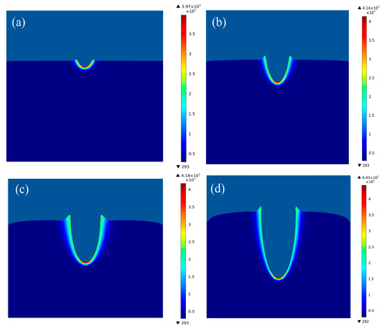
Figure 6.
Comparison of the depth of laser perforation under different laser powers at the same time: (a) 1200 W, (b) 2000 W, (c) 3000 W, and (d) 3500 W.
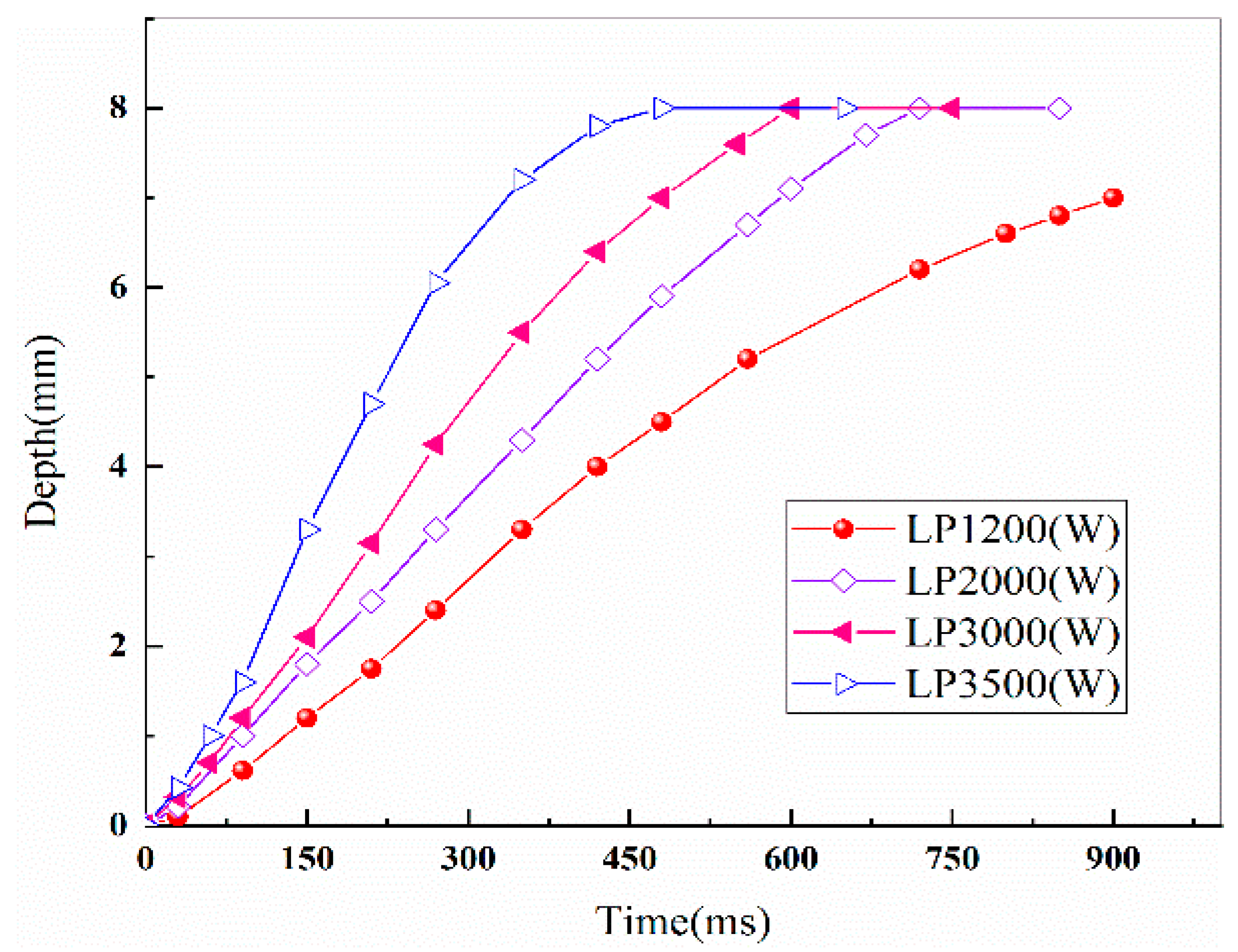
The variation in fluid volume fraction at different times during the laser drilling of carbon steel under different laser powers is shown in Figure 7. By comparing the perforation process at different powers, it can be seen that the flow of the melt was slow when the laser power was 1200 W or 2000 W, as shown in Figure 7a,b. When the laser power was increased to 3000 W, the quality of the surface of the processed product was better, with the product exhibiting a smooth surface, as shown in Figure 7c. When the laser power was 3500 W, the excessive power caused the product surface to appear inhomogeneous, with excessive heat transfer caused by deformation and producing a lot of splash, as shown in Figure 7d. The change in laser perforation depth with time under different laser powers can also be observed in Figure 8. It can be seen that, when the laser power was 1200 W, the drilling did not penetrate entirely the thick wall of the material; however, when the laser power was too large, i.e., 3500 W, the aperture size during the drilling process increased rapidly, a phenomenon which can cause deformation. When the laser power was 3000 W, the process of perforation could be finished with high efficiency and quality.
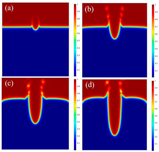
Figure 7.
Changes in fluid volume fraction at the same time of laser drilling under different laser powers: (a) 1200 W, unable to penetrate; (b) 2000 W, slow processing; (c) 3000 W, the surface is flat; (d) 3500 W, the surface begins to deform.
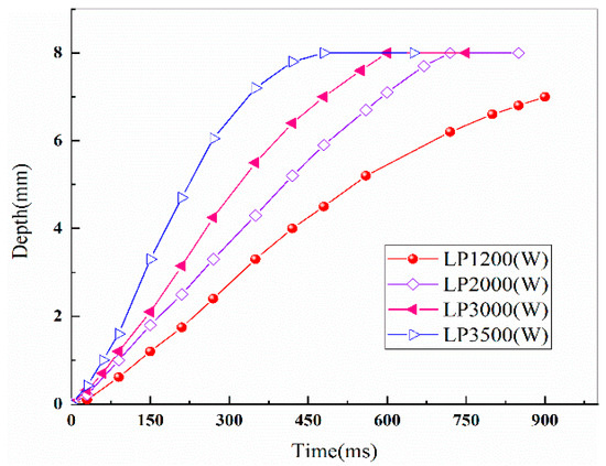
Figure 8.
Comparison of the hole depth over time under different laser powers.
4.3. Effect of the Laser Heat Source Radius
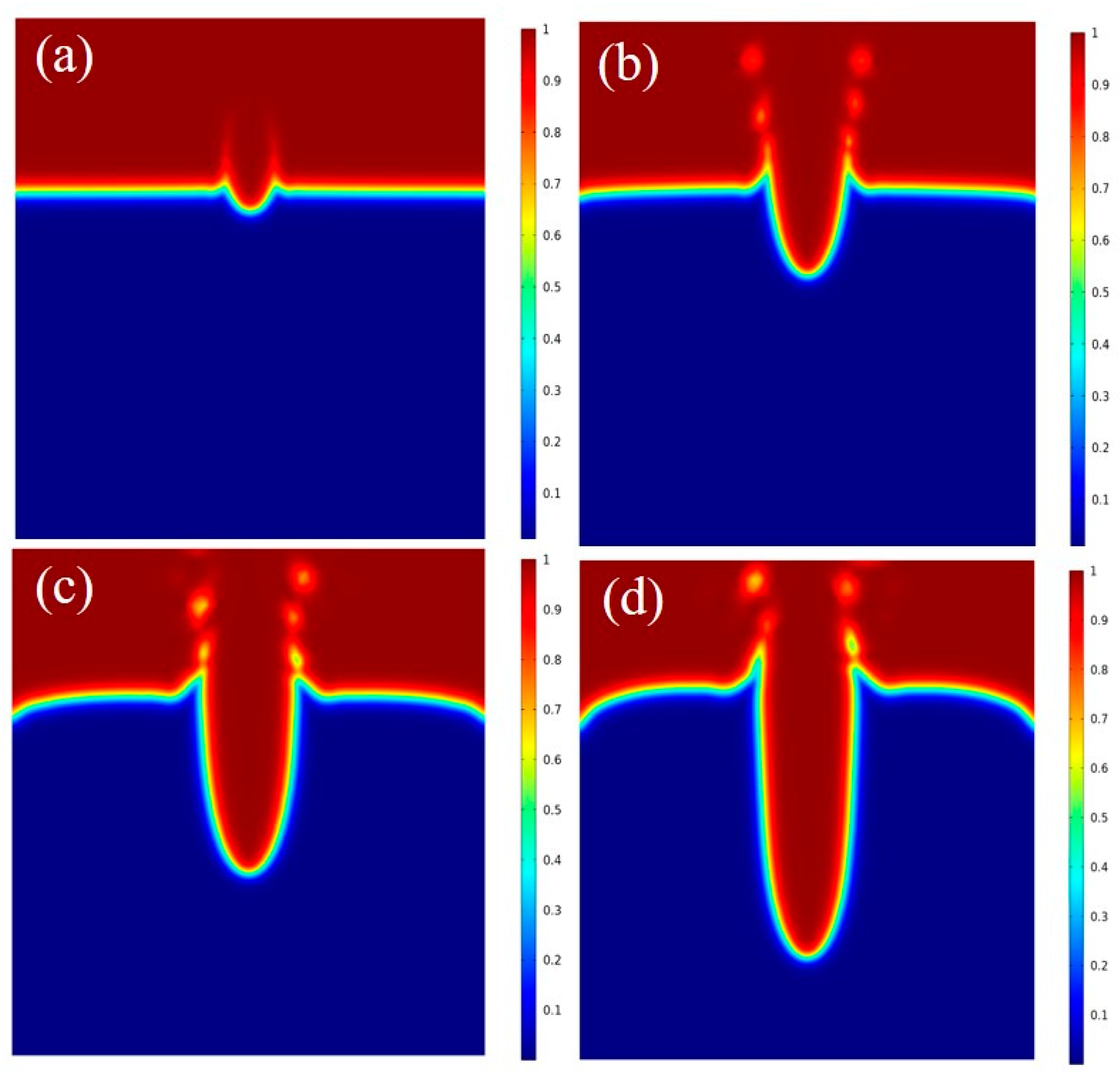
The radius of the laser heat source is an important factor affecting the quality of perforation. In this study, four parameters of laser heat source radius, 0.5 mm, 0.4 mm, 0.30 mm, and 0.15 mm, were selected to analyze their influence on the drilling processing. During the drilling processing, the energy generated by the laser beam acted on the surface of the material. At a time of 90ms, the laser processing depth varied with the radius of the heat source, as displayed in Figure 9. It can be concluded that the larger the radius of the laser heat source, the lesser energy is absorbed during the perforation process, leading to an increase in the time required to drill through the material. As shown in Figure 9a,b, when the radius of the heat source was 0.5 mm and 0.4 mm, the depth of the hole was 0.15 mm and 0.55 mm, respectively. The long drilling time caused the surface to melt and it could not be drilled further. When the radius of the heat source was reduced to 0.30 mm and 0.15 mm, the depth of the hole increased to 1.20 mm and 2.45 mm, respectively, as shown in Figure 9c,d. It can be concluded that, when the perforation depth and time achieved a reasonable ratio, the drilling progressed further before the solidification of the melt occurred, thus ensuring that the hole wall was smooth and no folds were generated.
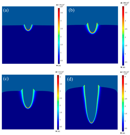
Figure 9.
Depth of the hole processed by laser drilling under different laser heat source radii: (a) 0.5 mm, processing depth of 0.15 mm, (b) 0.40 mm, processing depth of 0.55 mm, (c) 0.30 mm, processing depth of 1.20 mm, and (d) 0.15 mm, processing depth of 2.45 mm.
The variation in the volume fraction of the molten liquid under different radii of the laser heat source is shown in Figure 10. Perforation by a laser with a radius of 0.5 mm took substantially longer than that by a laser with a radius of 0.3 mm, a phenomenon which affected the productivity significantly, as shown in Figure 10a,c. The smaller the radius of the laser heat source, the more concentrated the energy. When the heating radius was smaller, the shape of the hole was smaller. The shape of the hole in the processed material was conical, as shown in Figure 10d.
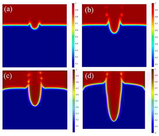
Figure 10.
Variation in fluid volume fraction of the molten liquid under different radii of the laser heat source at the same time: (a) 0.5 mm, (b) 0.40 mm, (c) 0.30 mm, (d) 0.15 mm.
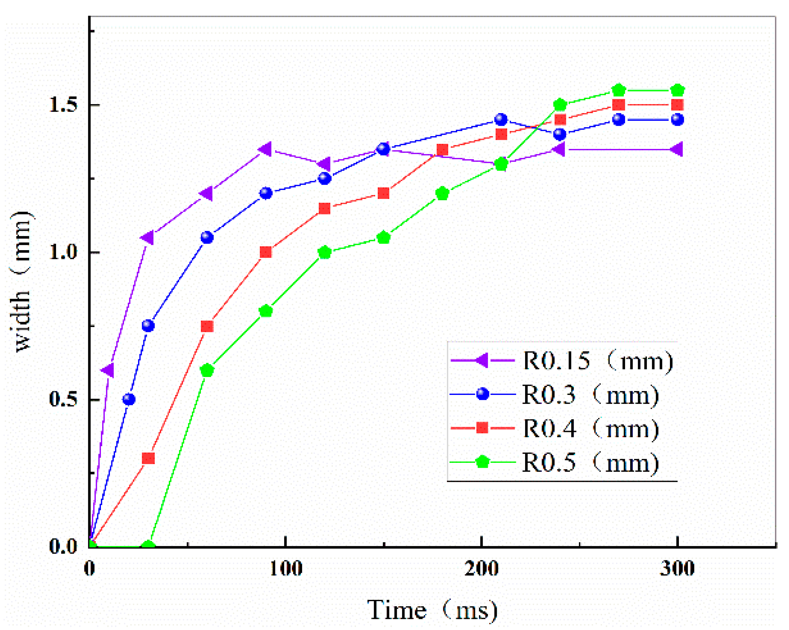
When the heat was concentrated, the contact area between the laser and the material was small, a phenomenon which can lead to more splashing of the molten liquid. Under the 0.15 mm heat source radius condition, the molten liquid sprayed excessively, sometimes resulting in laser drilling processing quality being lower than that achieved under the 0.3 mm heat source radius condition. The change in hole width under different heat source radii is shown in Figure 11, which shows that, when the heat source radius was 0.3 mm, the heat was concentrated, the processing time was short, and the time required to stabilize perforation was short too.
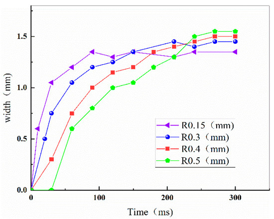
Figure 11.
Variation in the width dimension of the holes with time during laser drilling processing.
Based on the above numerical simulation results, the optimized laser perforation process parameters for carbon steel materials are obtained: a laser heat source radius of 0.3 mm and a laser power of 3000 W, both of which were used for the experiments. The experimental results are shown in Figure 12. It can be observed that the experimental samples perforated under the optimized laser perforation process parameters had a good surface roughness, and the size of the holes was accurate. In addition, the accumulation of molten liquid in the hole was reduced during the laser drilling process, as well as the slag splash.
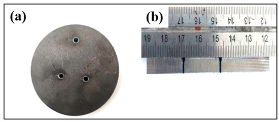
Figure 12.
Laser-drilled sample prepared under the optimized laser perforation process parameters: (a) perforated surface, (b) perforated section.
5. Conclusions
In this work, the phenomena of melt injection and slag splashing in laser drilling of carbon steel materials were investigated by numerical simulation method combined with experimental methods. The process parameters were optimized in order to improve the surface quality of the material following laser perforation, and the main conclusions of the study are as follows:
- (1)
- Considering the splash evolution of the material during the complex drilling process, the transient evolution of the temperature field, the flow of the molten fluid, the geometrical changes, and the absorption of the laser energy during the laser drilling process were investigated. The simulated borehole dimensions were consistent with the experimental results. The different process parameters had a great influence on the distribution of the temperature field and the behavior of the fluid flow in the molten pool, as well as on the morphology of the perforation. Results show that, when the pulsed laser beam acted on the surface of carbon steel, the heat diffusion coefficient was high, the temperature gradient was small, and the fluid region of the hole wall was prone to produce a large number of melt jets. The molten liquid and the molten pool undergo violent oscillations to produce splashing, which greatly affects the efficiency of the perforation and the quality of the molding.
- (2)
- Heat transfer and flow behavior played an important role in the carbon steel drilling process. The relationship between the melt sputtering process and the process parameters were verified. The laser power and the laser heat source radius determined the energy density transmitted to the materials. With the increase in laser power and the decrease in laser heat source radius, the time required for perforation decreased, the flow of melt accelerated, the perforation efficiency increased, and the hole wall became smoother, but the spattering increased.
- (3)
- The quasi-quantitative relationship between melt injection and the processing parameters of laser power and laser heat source radius was established by combining the results from both the numerical simulation analysis and the experiments. The optimized laser drilling processing parameters of carbon steel material were obtained: a laser heat source radius of 0.3 mm and a laser power of 3000 W, both of which were also verified by the experimental test where the buildup of the melt inside the hole was reduced, the degree of slag splash was lower, and a smooth and slag-free perforated surface was obtained.
These findings can help reduce the machining defects in carbon steel with excellent mechanical properties by optimizing the laser drilling processing parameters.
Author Contributions
Experiment test, data curation, writing—original draft: S.L.; funding acquisition, analysis, writing—review& editing: F.L.; supervision: Y.L. and J.E.; project administration: J.Y. All authors have read and agreed to the published version of the manuscript.
Funding
The authors acknowledge funding from the Science Foundation of the Yunnan Provincial Science and Technology Department (No. 202401AT070362, 202101AT070085, 202001AT070082) and the Science and Technology Major Project of Yunnan Province (No. 202202AG050004).
Data Availability Statement
The original contributions presented in the study are included in the article, further inquiries can be directed to the corresponding authors.
Conflicts of Interest
The authors declare no conflicts of interest.
References
- Liu, Y.; Zhu, H.-N.; Pei, Z.-D.; Kong, Y.-F.; Xu, J.-J. Molecular dynamic simulations of surface morphology and pulsed laser deposition growth of lithium niobate thin films on silicon substrate. Chin. Phys. B 2015, 24, 056802. [Google Scholar] [CrossRef]
- Wang, J.; Wang, H.-P.; Lu, F.; Carlson, B.E.; Sigler, D.R. Analysis of Al-steel resistance spot welding process by developing a fully coupled multi-physics simulation model. Int. J. Heat Mass Transf. 2015, 89, 1061–1072. [Google Scholar] [CrossRef]
- Zhang, T.-Z.; Jia, Z.-C.; Cui, H.-C.; Zhu, D.-H.; Ni, X.-W.; Lu, J. Analysis of melt ejection during long pulsed laser drilling. Chin. Phys. B 2016, 25, 054206. [Google Scholar] [CrossRef]
- Duan, W.; Wang, K.; Dong, X.; Mei, X.; Wang, W.; Fan, Z. Experimental characterizations of burr deposition in Nd:YAG laser drilling: A parametric study. Int. J. Adv. Manuf. Technol. 2014, 76, 1529–1542. [Google Scholar] [CrossRef]
- Voisey, K.T.; Clyne, T.W. Laser drilling of cooling holes through plasma sprayed thermal barrier coatings. Surf. Coat. Technol. 2004, 176, 296–306. [Google Scholar] [CrossRef]
- Leitz, K.-H.; Koch, H.; Otto, A.; Schmidt, M. Numerical simulation of process dynamics during laser beam drilling with short pulses. Appl. Phys. A 2011, 106, 885–891. [Google Scholar] [CrossRef]
- Otto, A.; Koch, H.; Leitz, K.-H.; Schmidt, M. Numerical Simulations—A Versatile Approach for Better Understanding Dynamics in Laser Material Processing. Phys. Procedia 2011, 12, 11–20. [Google Scholar] [CrossRef]
- Geiger, M.; Leitz, K.H.; Koch, H.; Otto, A. A 3D transient model of keyhole and melt pool dynamics in laser beam welding applied to the joining of zinc coated sheets. Prod. Eng. 2009, 3, 127–136. [Google Scholar] [CrossRef]
- Afrasiabi, M.; Wegener, K. 3D Thermal Simulation of a Laser Drilling Process with Meshfree Methods. J. Manuf. Mater. Process. 2020, 4, 58. [Google Scholar] [CrossRef]
- Pattanayak, S.; Panda, S.; Dhupal, D. Laser micro drilling of 316L stainless steel orthopedic implant: A study. J. Manuf. Process. 2020, 52, 220–234. [Google Scholar] [CrossRef]
- Jia, X.; Chen, Y.; Liu, L.; Wang, C.; Duan, J.A. Advances in Laser Drilling of Structural Ceramics. Nanomaterials 2022, 12, 230. [Google Scholar] [CrossRef] [PubMed]
- Dada, M.; Popoola, P.; Mathe, N.; Adeosun, S.; Aramide, O. 2D numerical model for heat transfer on a laser deposited high entropy alloy baseplate using Comsol Multiphysics. Mater. Today Proc. 2022, 50, 2541–2546. [Google Scholar] [CrossRef]
- Parekh, R.; Buddu, R.K.; Patel, R.I. Multiphysics Simulation of Laser Cladding Process to Study the Effect of Process Parameters on Clad Geometry. Procedia Technol. 2016, 23, 529–536. [Google Scholar] [CrossRef]
- Yaagoubi, H.; Abouchadi, H.; Taha Janan, M. Numerical simulation of heat transfer in the selective laser sintering process of Polyamide12. Energy Rep. 2021, 7, 189–199. [Google Scholar] [CrossRef]
- Zhang, Y.; He, X.; Yu, G.; Li, S.; Tian, C.; Ning, W.; Zhang, Y. Dynamic evolution of keyhole during multi-pulse drilling with a millisecond laser on 304 stainless steel. Opt. Laser Technol. 2022, 152, 108151. [Google Scholar] [CrossRef]
- Zhang, S.; Fan, Y.; Huang, Y.; Yang, X.; Zhang, M.; Luo, J.; Deng, G.; Zhou, Q.; Song, H.; Wang, Y. Improvement of the surface condition of laser-drilled holes via a dual-wavelength double-pulse train. Opt. Laser Technol. 2023, 157, 108681. [Google Scholar] [CrossRef]
- Lee, H.; Lim, C.H.J.; Low, M.J.; Tham, N.; Murukeshan, V.M.; Kim, Y.-J. Lasers in additive manufacturing: A review. Int. J. Precis. Eng. Manuf.-Green Technol. 2017, 4, 307–322. [Google Scholar] [CrossRef]
- Cao, Z.; Dong, M.; Liu, K.; Fu, H. Temperature Field in the Heat Transfer Process of PEEK Thermoplastic Composite Fiber Placement. Materials 2020, 13, 4417. [Google Scholar] [CrossRef] [PubMed]
- Li, T.Q.; Wu, C.S.; Feng, Y.H.; Zheng, L.C. Modeling of the thermal fluid flow and keyhole shape in stationary plasma arc welding. Int. J. Heat Fluid Flow 2012, 34, 117–125. [Google Scholar] [CrossRef]
- Tan, W.; Bailey, N.S.; Shin, Y.C. Investigation of keyhole plume and molten pool based on a three-dimensional dynamic model with sharp interface formulation. J. Phys. D Appl. Phys. 2013, 46, 055501. [Google Scholar] [CrossRef]
- Courtois, M.; Carin, M.; Le Masson, P.; Gaied, S.; Balabane, M. A complete model of keyhole and melt pool dynamics to analyze instabilities and collapse during laser welding. J. Laser Appl. 2014, 26, 042001. [Google Scholar] [CrossRef]
- Rai, R.; Elmer, J.W.; Palmer, T.A.; DebRoy, T. Heat transfer and fluid flow during keyhole mode laser welding of tantalum, Ti–6Al–4V, 304L stainless steel and vanadium. J. Phys. D Appl. Phys. 2007, 40, 5753–5766. [Google Scholar] [CrossRef]
- Zhang, Y.; Shen, Z.; Ni, X. Modeling and simulation on long pulse laser drilling processing. Int. J. Heat Mass Transf. 2014, 73, 429–437. [Google Scholar] [CrossRef]
- Ya, W.; Pathiraj, B.; Liu, S. 2D modelling of clad geometry and resulting thermal cycles during laser cladding. J. Mater. Process. Technol. 2016, 230, 217–232. [Google Scholar] [CrossRef]
- Hirano, K.; Fabbro, R.; Muller, M. Experimental determination of temperature threshold for melt surface deformation during laser interaction on iron at atmospheric pressure. J. Phys. D Appl. Phys. 2011, 44, 435402. [Google Scholar] [CrossRef]


Disclaimer/Publisher’s Note: The statements, opinions and data contained in all publications are solely those of the individual author(s) and contributor(s) and not of MDPI and/or the editor(s). MDPI and/or the editor(s) disclaim responsibility for any injury to people or property resulting from any ideas, methods, instructions or products referred to in the content. |
© 2024 by the authors. Licensee MDPI, Basel, Switzerland. This article is an open access article distributed under the terms and conditions of the Creative Commons Attribution (CC BY) license (https://creativecommons.org/licenses/by/4.0/).