1. Introduction
Commercially pure titanium (CP-Ti) and titanium alloys are extremely attractive materials for a number of industries and find diverse applications [
1,
2,
3,
4,
5]. Titanium has low density and, at the same time, considerable strength, along with very good corrosion resistance in various corrosive environments. Titanium exists in two allotropic states—low-temperature (α-phase) with a hexagonal close-packed crystal structure (hcp) and high-temperature (β-phase) with a cubic body-centered crystal structure (bcc). The phase transition temperature for pure titanium is 882 °C [
6]. The ability to exist in two different titanium phases and the ability to phase transition at a different temperature depending on the type and amount of alloying elements determine the diverse properties of titanium alloys. The elements that titanium can be alloyed with are generally divided into α-stabilizers and β-stabilizers. As the name suggests, the stabilizing element seeks to retain the maximum amount of the respective phase in the alloy at room temperature. Depending on the added stabilizers, titanium alloys are divided into α, α + β, and β (metastable and stable). α alloys are characterized by low strength and good corrosion resistance, and they are not used for structural applications. The α-stabilizers increase the phase transition temperature. α + β alloys are the most widely used class of titanium alloys. They are characterized by high strength, good durability and wear resistance, and excellent corrosion resistance, maintaining these characteristics at high temperatures. β alloys are used in structures requiring high strength and good fracture resistance. The addition of β-stabilizers leads to a decrease in the phase transition temperature. This class of titanium alloys has excellent biocompatibility and finds biomedical applications. Among the alloys of the α + β class, the most widely used alloy is Ti6Al4V (Ti64). The composition of the alloy includes 6% aluminum as an α-stabilizer and 4% vanadium as a β-stabilizer. The alloy is characterized by a higher phase transition temperature, much higher yield strength and tensile strength, a higher hardness, and lower thermal conductivity compared to pure titanium [
6,
7,
8].
Welding is one of the most commonly used technological processes used for joining two or more components together, which could be made of similar (the same) or dissimilar materials. Over the years, a lot of different types of welding have been developed, employing different setups with different sources of heat. Commercially pure titanium and titanium alloys are most commonly welded using arc welding technologies such as gas metal arc welding (GMAW) [
9] and gas tungsten arc welding (GTAW) [
10,
11,
12,
13]. Pasang et al. [
11] studied the possibility of forming similar joints between CP-Ti, Ti64, and Ti5553 and reported that the obtained welds had superb mechanical properties. Lathabai et al. [
12] studied the influence of the welding technique on the structure and mechanical properties of CP-Ti. Their investigations suggested a minimal difference between the resultant mechanical properties of “keyhole”-type welds and the conventional multipass welds. Bendikiene et al. [
13] studied how the variation of the welding speed affected the mechanisms of formation of defects and their concentration along the volume of the weld seam. During their investigations, they determined an optimum welding speed where the absence of defects was observed. As attractive as arc welding techniques are, there is also a vast number of other techniques used in practice for welding Ti and its alloys such as friction stir welding [
14,
15], plasma arc welding [
16], laser welding, and electron-beam welding [
10,
17,
18,
19,
20]. However, in most cases, the process of welding is performed in the air of a short-lived protective environment such as inert gas flows, etc. It is well known that titanium and some of its alloys are highly reactive to O
2 and N
2. Their concentration in the surrounding environment is of vital importance for the formation of defects in the weld such as blow holes, gas pores, cracks, and other defects [
21]. In order to avoid this, electron-beam welding (EBW) can be employed, which is performed in a high vacuum environment where the purity of the formed joints is guaranteed by the absence of gas molecules in the surrounding environment. Furthermore, the employed electron-beam technique has reportedly the lowest HAZ compared to other methods. However, a trending issue with welding by using concentrated energy fluxes is the high heat input followed by rapid cooling. This could result, depending on the material, in the formation of defects within the structure of the weld seam and could also lead to phase transformations, which reduce its properties and longevity. Mitchell et al. [
22], for example, studied the possibility of welding CP-Ti and titanium alloys using an electron-beam unit with a high accelerating voltage of 150 kV and a low current of the electron beam of 3 mA. All of the obtained results showed a reduction in the ductility of the welds compared to that of the base materials.
A modern solution to this problem is the application of fillers (wires, foils or others) between the substrate materials that moderate the structure of the weld seams and improve their mechanical properties [
23,
24,
25,
26]. This is applicable in all cases where electron-beam welding and laser-beam welding are concerned. Prior investigation was performed where the possibility of welding CP-Ti and Ti64 was studied, and successful welds were formed [
27]. The samples in that work showed excellent mechanical properties in the form of microhardness and tensile strength. However, the yield strength of those specimens was significantly lower compared to that of the raw materials. This indicates that the formed specimens have a higher affinity to plastic deformation compared to the raw materials, which is completely inapplicable in some areas of industrial design. Furthermore, the investigations of applying fillers during the electron-beam welding process are limited, which prompts the need for further investigation of the matter.
Due to this, in the present work, we applied a new methodology for moderating the structure and mechanical properties of electron-beam-welded joints by applying Nb, V, and Cu fillers using magnetron sputtering. The influence of the formed fillers on the structure and properties of the obtained samples was studied, and the results were discussed as a function of possible practical applications.
2. Materials and Methods
For the purpose of this research, welding plates with dimensions of 100 × 50 × 8 mm were used. The CP-Ti had a purity of 99.9%. The chemical composition in wt.% of the Ti64 alloy was as follows: 6.18% Al, 3.97% V, 0.14% Fe, 0.009% C, 0.012% N, 0.0045% H, 0.135% O, and bal. Ti. A layer of filler material was deposited on the cross-section of the planes with a surface area of 800 mm
2. Niobium (Nb), copper (Cu), and vanadium (V) were used as filler materials. The thermophysical characteristics of these elements are shown in
Table 1. Copper has the lowest melting point and the highest thermal conductivity. Niobium and vanadium are characterized by a much lower thermal conductivity compared to copper. Vanadium has the highest specific heat capacity and significantly lower density compared to copper and niobium, but despite the high heat capacity, it has the smallest value of the coefficient of thermal conductivity.
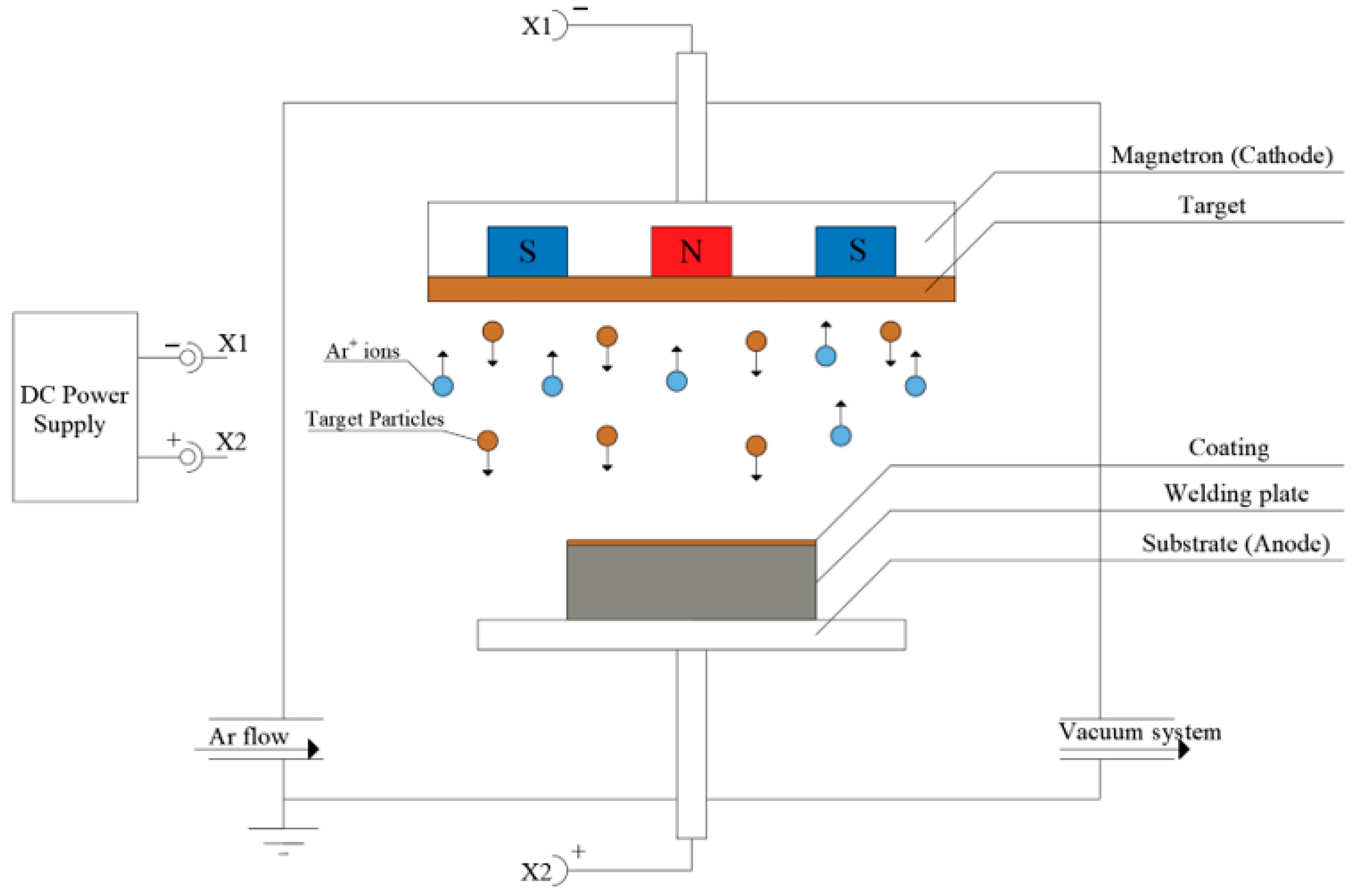
The Nb, V, and the Cu coatings were deposited using magnetron sputtering. The process is shown in
Figure 1. The argon ions bombard the target material (TM), which results in the production of TM particles that condense atop the surface of the welding plates. The technological conditions are presented in
Table 2. In any case, before the deposition process begins, cathodic cleaning is performed at a working pressure of 7 × 10
−2 mbar, discharge voltage of 900 V, and discharge current of 0.1 A.
Subsequently, the three different layers are deposited. The Nb, V, and Cu layers are deposited at slightly different working pressures of 8 × 10⁻⁴ mbar, 6 × 10⁻⁴ mbar, and 7 × 10⁻⁴ mbar, respectively. The discharge current in all cases was 1 A, and the discharge voltage was in the range of 410–550 V. The deposition time in the case of the Nb and V layers was 150 min, and in the case of the Cu layer, it was 75 min. As a result, the formed layers had a thickness in the range of 10–11 µm. The different technological conditions of layer deposition are determined by the different potentials of the materials to form negatively charged ions as a result of the inert gas bombardment.
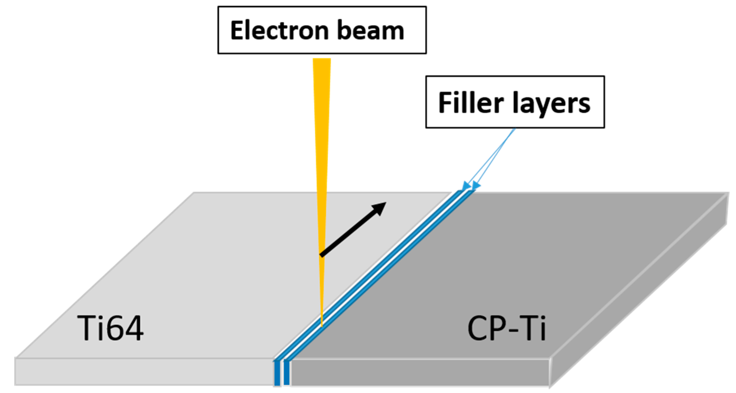
After the coatings were deposited on the contact surfaces of the plates, electron-beam welding was performed using an Evobeam Cube 400 (Evobeam GmbH, Nieder-Olm, Germany) welding unit. The EBW was performed using the same technological conditions in all considered cases as follows: welding speed v = 10 mm/s; accelerating voltage U = 60 kV; and beam current I
b = 25 mA. The schematic of the electron-beam welding of the CP-Ti and Ti64 welding plates with the filler is presented in
Figure 2.
Scanning electron microscopy (SEM) was used to study the microstructure of the welded specimens. Back-scattered electrons were employed. Information on the chemical composition of the studied samples was obtained via energy dispersive X-ray spectroscopy (EDX). EDX analysis was performed on separate points of the samples and also in a liner direction. The unit used for the experiments was a Tescan Lyra III (Tescan, Brno, Czech Republic).
The phase analysis was conducted using X-ray diffraction (XRD) on a Bruker D8 Advance (Bruker, Billerica, MA, USA) diffractometer. The applied method was coupled two theta using CuKα radiation with a wavelength 1.54 Å. The range of measurements was 30–70°. The experiments were realized with a 0.05° step with a 0.25 s time step.
Subsequent to the X-ray diffraction experiments, residual stress (σx) measurements were performed using the same diffractometer. In this case, CrKα radiation was used. The measurements were performed using the sin2ψ method. The diffraction angle was in the range between 60° and 62.5°. Within this range, (61.36°) was the studied diffraction maxima corresponding to the αTi phase, which corresponds to the (101) crystallographic plane. The step size of the experiments was 0.1°, and the time step was set to 1 s per step. The elastic constants s1 and ½s2 of the αTi phase for the (101) crystallographic plane were assumed to be −2.947 × 10⁻⁶ and 1.188 × 10⁻⁵. The residual stresses observed in the present research are along the “x” axis, in other words, perpendicular to the cross-section of the weld seams.
The Vickers hardness was determined using a ZwickRoell Dura Scan 10/20 G5 (ZwickRoell, Ulm, Germany) semi-automatic microhardness tester applying a load of 50 g. The measurements were performed following a linear trajectory perpendicular to the weld seam formation vector. The ISO 6507-1 standard [
28] was closely followed during this experimental stage.
A ZwickRoell Vibrophore 100 (ZwickRoell, Ulm, Germany) tensile tester was used to perform the tensile experiments. A static mode was employed for all samples with a constant stress rate of 30 MPa/s in accordance with the ISO 6892-1-Method B standard [
29]. The shape and dimensions of the tensile test samples are shown in
Figure 3. The elongation (ε) of the samples was measured by the build-in the machine measuring line, and the software calculated the percentile increase in the length of the samples.
3. Results
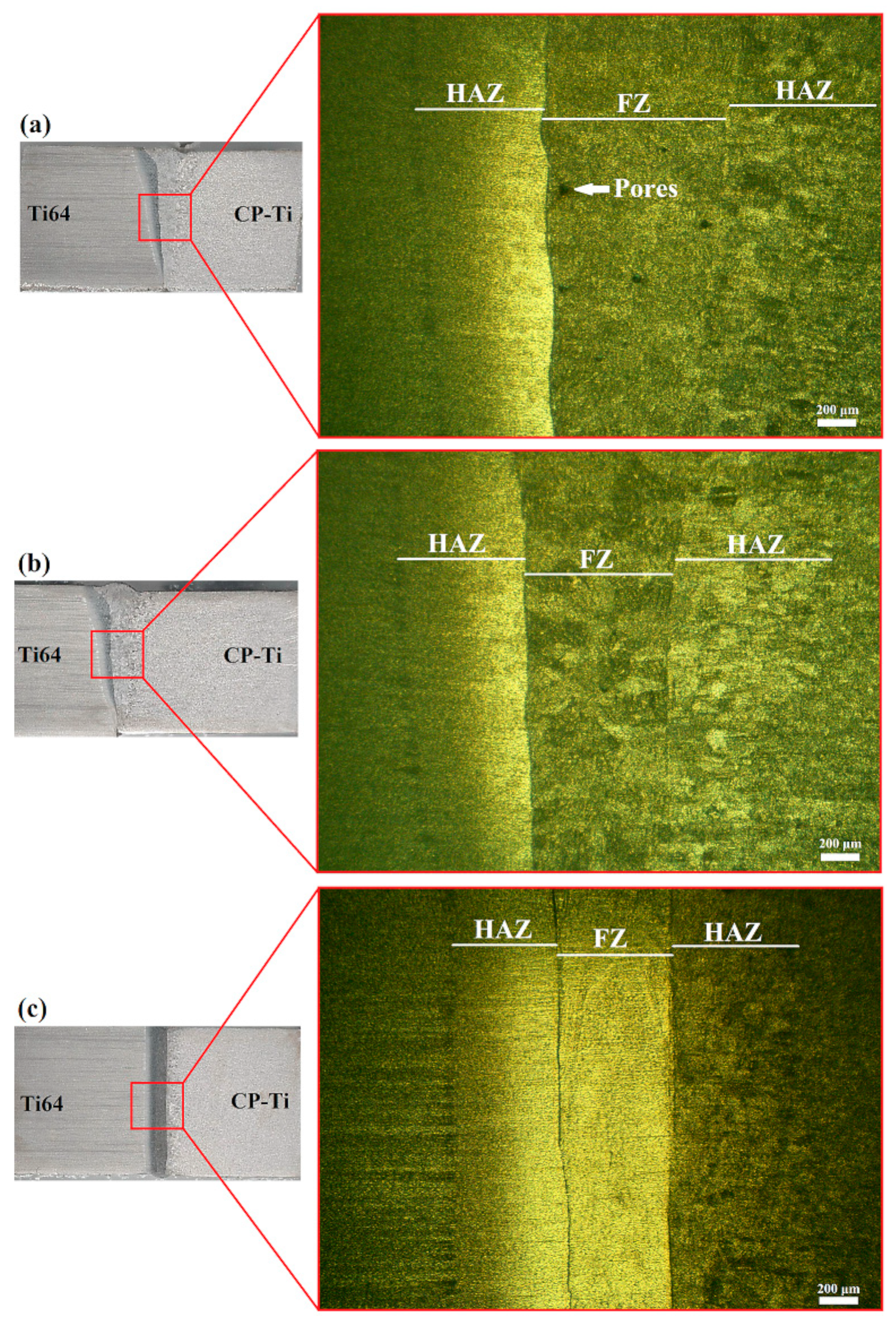
The optical images of the formed welds are shown in
Figure 4.
Figure 4a corresponds to the Nb filler sample,
Figure 4b to the V filler one, and
Figure 4c to the Cu filler one. Evidently, both the Nb and V filler welds have the characteristic electron-beam welding “keyhole”-shaped weld seam [
30,
31]. By contrast, the Cu filler weld seam has an even shape without major changes in its width. The heat-affected zone (HAZ) is more pronounced in the Ti64 region than in the CP-Ti region. The sample with the Nb filler has a seam with an average thickness of 700 μm, the sample formed with the V filler also has a width of 700 μm. The Cu filler sample has an average thickness of 400 µm, which, as mentioned, remains about the same along the entire cross-section of the specimens. Along with the shape and size of the weld seams, the optical microscope images also show the presence of a number of pores within the FZ of the weld formed with the Nb filler.
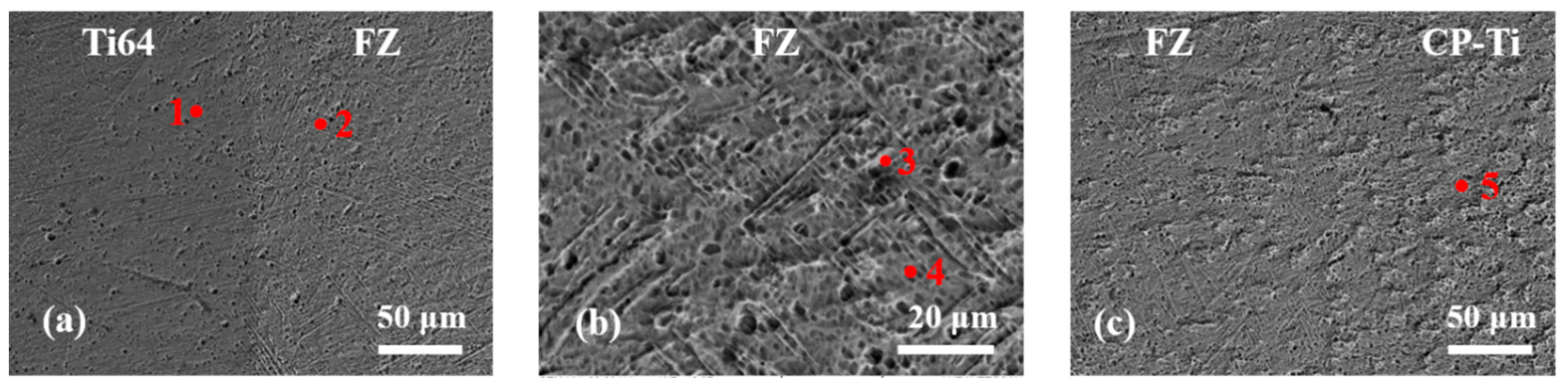
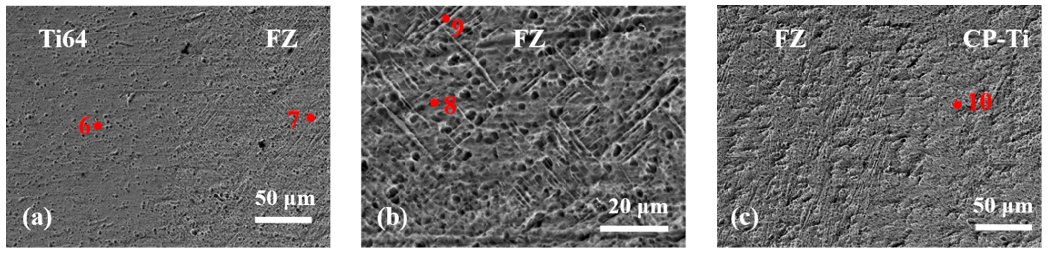
Figure 5,
Figure 6 and
Figure 7 present SEM images with different magnifications of parts of the cross-section of the investigated specimens. The fusion zone (FZ) and the FZ–base metal interfaces are shown. The chemical composition of the marked points located in
Figure 5,
Figure 6 and
Figure 7 was investigated using EDX, and the results are summarized in
Table 3.
In the FZ of the samples welded with the Nb and V filler (
Figure 5 and
Figure 6), a clearly visible αTi lamellar structure is present along with a number of α’-Ti martensitic formations. However, in the fusion zone of the specimen welded with the Cu filler (
Figure 7), no such structure is observed. Many small particles are spread across the volume of this sample, however, which may be a result of the formation of intermetallic phases or may be caused by the incomplete dissolution of copper within the fusion zone. In all cases, some porosity can also be observed in the structure of the samples. Defects such as these can be caused by the high heating and cooling rates during the welding process [
31].
As mentioned above,
Table 3 presents the data obtained from the EDX analysis. The results of the Ti64-Nb-CP-Ti sample indicate up to 5% concentration of Nb in the volume of the fusion zone. Almost negligible values of up to 0.4% were detected closer to the edge of the fusion zone in the boundary between the FZ and the base materials (BM). This means the Nb concentration was contained strictly to the fusion zone. No large undissolved Nb particles were observed. The sample prepared using the V filler shows a slightly higher concentration of V in the fusion zone of the specimens of up to 1.65% compared to the Nb filler specimen, with 0.9%, and the Cu filler specimen, with 1.14%. In either case, due to the low Ti64 inclusions in the welding seam, the concentration of V is significantly lower compared to that of the base Ti64 alloy. Zhang et al. [
32] studied the effect of the vanadium content on the structure and mechanical properties of wire arc additively manufactured Ti-6Al-xV specimens. They reported that an increase in the V content resulted in a decrease in the size of the lamellar αTi structure. This significantly improve the mechanical properties of the manufactured specimens. In the present study, in all cases, the vanadium content of the fusion zone is too low to affect the size of the formed lamellae; however, in the case of the sample welded with the Cu filler, no lamellar structure is observed along with no evidence of α’-Ti martensitic transformation. This means that it is possible that the leading cause of the refining of the structure of the weld seam may be the application of the copper filler between the welding plates.
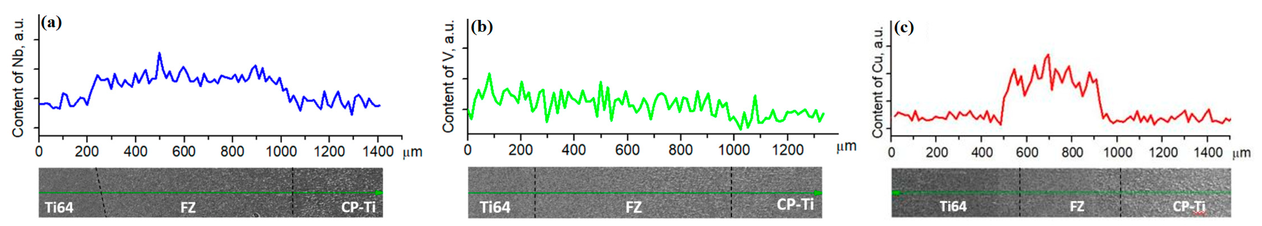
Figure 8 presents the results of EDX analysis performed by following a linear pattern starting from the Ti64 side, across the fusion zone, and ending on the CP-Ti side. Large concentration peaks of Nb and Cu are observed when studying the fusion zone of the respective samples (
Figure 8a,c).
Figure 8b shows the results for the V-doped sample. Evidently, due to the presence of V in the Ti64 alloy, it disperses evenly through the weld seam, and no visible spikes in the concentration of this element are observed.
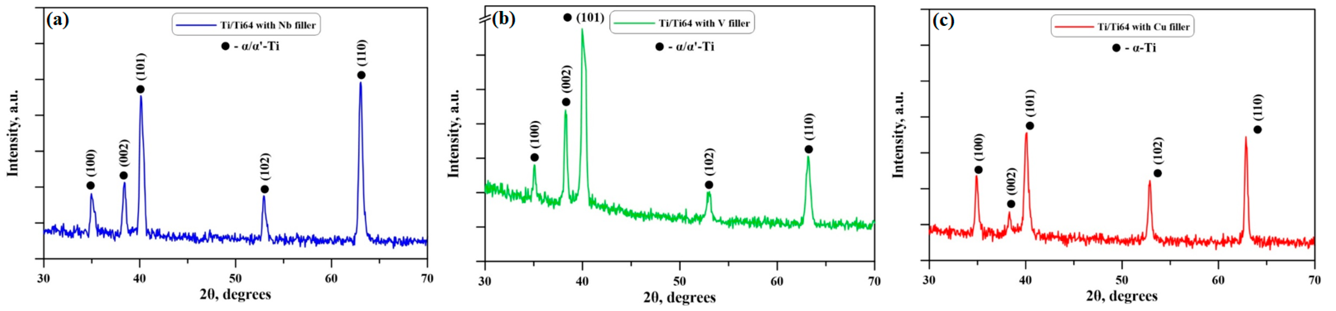
The X-ray diffraction patterns of the samples welded with the Nb, V, and Cu fillers are presented in
Figure 9. A polycrystal structure can be observed in all cases. No amorphous-like halos were detected, suggesting the absence of such solid structures on the surface of the samples. During the experiments, diffraction maxima corresponding to the (100), (002), (101), (102), and (110) crystallographic planes were detected. According to the International Centre for Diffraction Data (ICDD) database PDF #00-001-1198, all peaks indicated in the present research are of the αTi phase, which has a hexagonal crystal structure. No peaks corresponding to βTi were observed. Similar results were obtained by Boonchuduang et al. [
33], who also performed XRD experiments on CP-Ti specimens. Increased intensity of the reflections of the (002) plane was observed concerning the samples formed using the Nb and V fillers. This could be attributed to the observed SEM change in the structure of the samples and the formation of an αTi lamellar structure along with some martensitic formations. This could possibly be due to the α’Ti martensitic phase transformation and the decrease in the βTi phase. It could also mean that the studied area was closer to the Ti64 welding plate, which characterizes the same diffraction maxima with a higher intensity [
33].
Table 4 summarizes the calculations of the preferred crystallographic orientation (pole density) obtained theoretically using the calculations described by previous researchers [
34,
35]. Evidently, the texture of the welded samples without a filler and with the V filler is approximately the same. These results indicate no preferred crystallographic orientation of the samples towards a specific plane. However, adding copper as an interlayer between the welding plates results in the re-texturing of the samples and a preferred crystallographic orientation towards the {110} family of crystallographic planes. Replacing the interlayer material with Nb leads to an even higher P
{hkl} towards the {110} family of crystallographic planes.
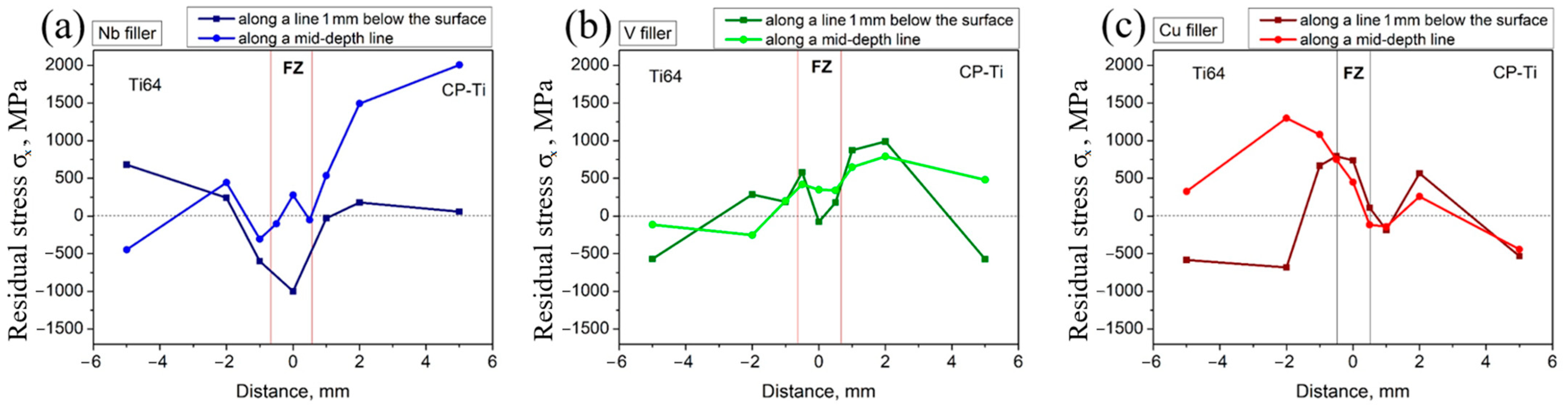
Figure 10 depicts the results of the obtained residual stress (σ
x) measurements. The experiments were performed 1 mm below the surface of the weld plates and in the middle of the weld seam. In all cases, the cross-section of the samples was studied. In all cases, positive and negative spikes of the residual stresses are observed corresponding to tensile stresses and compression stresses, respectively. The results for the samples formed using the Nb filler (
Figure 10a) show an interesting tendency: 1 mm below the surface of the weld seam, predominantly compression residual stresses are observed with a maximum value of −998 MPa. Compared to that, the ones observed in the middle of the weld seam are mostly tensile stresses with a peak of 278 MPa. Furthermore, multiple spikes in the residual stresses are observed in the second case close to the fusion zone where only a single large negative spike is observed at the top of the specimen. Looking at the results for the V filler, tensile residual stresses are mostly observed in the fusion zone. The maximum tensile stress at the top of the weld seam is 580 MPa, and the maximum value in the middle of the weld is 420 MPa. This indicates that using Nb and V fillers has led to the formation of higher residual stresses during the welding process at the top of the weld seam compared to its middle section. In the case of the sample formed using the Cu filler, the difference between the residual stresses at the top of the weld seam and in the middle is minimal. The maximum residual stress observed 1 mm below the surface of the weld is 794 MPa, and in the middle, 738 MPa. In this case, similar to the V and Nb filler samples, the observed stresses in the fusion zone are predominantly tensile stresses.
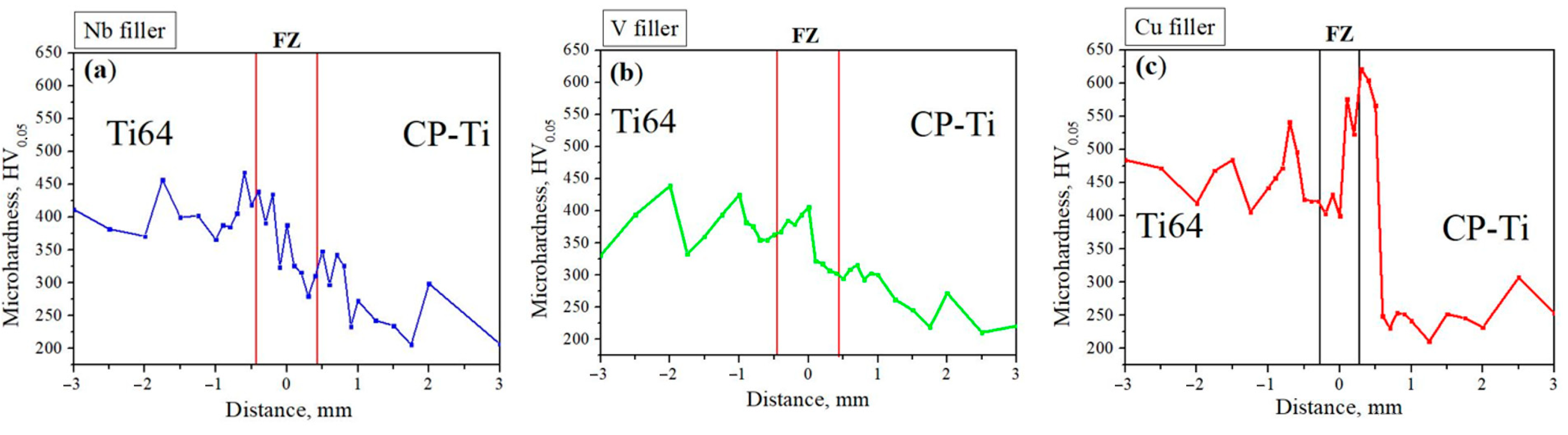
The measured microhardness values are presented in
Figure 11. An average Vickers hardness of 365 HV
0.05 was observed for the Ti64 welding plate. In comparison, the CP-Ti welding plate exhibited an average microhardness of 290 HV
0.05. Langdon et al. [
36] studied the change in the microhardness as a function of an applied high-pressure torsion process to CP-Ti specimens. They reported similar Vickers hardness values as the ones observed in the current experiments. Srivatsan et al. [
37] studied the microhardness of a Ti-6Al-4V alloy in detail and found that the average Vickers hardness was about 334 HV. The obtained results are within the margin of error of the measurement method, so an agreement between the two research teams [
36,
37] can be established. The microhardness values of the Nb and V fillers samples are approximately the same, with an average microhardness of 350 HV
0.05. Interestingly, the microhardness of the weld seam formed using the Cu filler is about 525 HV
0.05, which is significantly higher than that of the raw materials. As observed in the SEM experiments, the structure of both the Nb filler and V filler samples is highly similar, with the presence of a large quantity of coarse αTi lamellae along with some α’-Ti martensitic structures. As a result, the microhardness of the weld seam has increased compared to the raw CP-Ti material. However, in both cases, the microhardness of the weld seam does not increase beyond that of the raw Ti64 alloy. Comparatively, the microhardness in the fusion zone of the Cu filler sample is significantly higher than that of the raw materials as a result of the grain refinement prompted by the addition of copper to the structure. Also, the existence of fine precipitates within the weld seam in the case of Cu fillers could be considered a reason for the rise in the microhardness.
The stress–strain curves of the samples are presented in
Figure 12, and the quantitative data are presented in
Table 5. When comparing the three samples with filler and the sample without filler [
27], the influence of the beta-stabilizing fillers is clearly visible. The specimen welded with the vanadium filler showed the highest values of yield strength and ultimate tensile strength, as well as a high value of relative deformation. The specimen to which the Nb filler in the form of thin films was applied showed the lowest ultimate tensile strength amongst the three specimens. In addition, the elongation of that sample was only 4.8%. In the stress–strain curve of that sample, a sudden, almost premature drop was observed, indicating a sudden break of the specimens. The specimen welded with the copper filler exhibited the lowest yield strength and a good UTS. Lu et al. [
38] studied the correlation between the UTS and the microhardness of TC4-DT electron-beam-welded joints and constructed a UTS/HV curve. The results showed that with the increase in the microhardness, the UTS increase as well. However, in the present case, the YS of the copper doped sample was the lowest. It is known that the higher the YS/UTS ratio, the more brittle the samples. Since the YS/UTS ratio was the lowest in the case of the copper sample, the last should theoretically exhibit the best plasticity compared to the other samples. This was, of course, confirmed by the highest elongation values. In either case, however, the tensile properties of the samples were highly similar and comparable. In addition, they improved over the ones of similar welds formed without the presence of fillers [
27].
4. Discussion
During the welding process, different shaped and sized weld seams formed as a function of the applied filler. The Nb and V filler welds had the same shape and size, while the Cu filler weld had a linear shape with little change in its width along the cross-section. Petrov et al. [
39] studied the heat transfer through welding plates during the process of EBW. They found that the isotherms were the most concentrated towards the top of the weld where the temperature was the highest. The temperature then dissipated through the materials, and the concentration of the isotherms (the temperature) decreased at the bottom of the weld seam. The difference in the temperature at the top of the weld and at the bottom during the EBW process caused the formation of a “keyhole” weld seam. Copper, however, is the second most conductive metal on Earth, which affected the transfer of the isotherms and unified the temperature distribution through the entire cross-section of the welding plates. This is the reason for the formation of the straight weld seam. The higher thermal gradient achieved during the welding process with the Cu filler also limited the inclusions of both the CP-Ti welding plate and the Ti64 one. This resulted in the formation of a uniform and more refined structure, which improved the mechanical properties of these specimens compared to the others.
The elements stabilizing the β-phase of titanium are divided into two types—isomorphous and eutectoid. Isomorphous types also have two types—with and without a monotectoidic reaction in the phase diagram. Isomorphous beta stabilizers form a solid solution with titanium, while eutectoids have limited solubility in titanium and form intermetallic phases with it according the reaction β → α + Ti
xA
y where A is the stabilizing element [
40]. The binary phase diagrams of Ti and each of the three elements that we used as fillers in our study have been already shown by the authors of [
41]. As can be seen from the binary diagrams of Ti-Nb and Ti-V, a solid solution of Nb and V with α-Ti should have formed in the weld seam. The current investigations confirm the presence of a solid solution between the titanium and the introduced niobium (or vanadium) additives as a deposited thin layer. The observed elongated α-Ti structure along with the partial transformation into the α’-Ti structure in the two samples, namely, the niobium and vanadium filler ones, is obtained as a result of the very high cooling rates that are characteristic of the electron-beam welding process [
42,
43]. In the case of the Cu filler sample, no elongated α-Ti structure was observed in the weld of the copper filler specimen, and there were no martensitic structures. The SEM images show the structure of pure α-titanium. It is possible that the observed nano-sized particles within the structure of the fusion zone are an intermetallic phase between copper and titanium or possibly undissolved copper. Copper and titanium can form a number of stable intermetallic compounds such as CuTi, Cu
2Ti, Cu
3Ti
2, and Cu
4Ti
3. The formation energy of the CuTi
2 phase is the smallest, and the potential for the formation of this particular phase is the highest compared to the others. However, during the current investigation, the exact composition of these tiny precipitates was not established, so definitive labeling of the last was impossible. The results of the current work confirm that copper can be used as a β stabilizing agent during the welding process. The most probable cause for this is that, as mentioned, copper has excellent thermal capabilities, which vastly improve the heat transfer during the EBW process. As a result of this, the heating/cooling cycle stabilizes and thus, the formation of lamellae structures is limited.
The observed texture change is due to the presence of undissolved Nb and Cu particles and/or due to the presence of precipitates (albeit nano-sized). Due to their presence, they influence the growth of titanium grains in a certain crystallographic orientation, which is maximally thermodynamically advantageous for the bonding between titanium crystals and other particles. The layering of crystals of the same type leads to the formation of defects between them and a lowering of the mechanical characteristics of the areas in which it occurs. This is because, from a thermodynamic point of view, although this is the most advantageous direction of growth, it is not necessarily also the most advantageous for obtaining optimum (maximum) structural strength and mechanical properties. Since vanadium is completely dissolved and introduced into the titanium structure, there we practically observe a homogeneous structure, which is confirmed by SEM. Looking at it, the welding zone is almost not visible. The structure changes due to the welding process and the different vanadium concentrations. In the case of copper, apparently no complete dissolution has occurred, and there may be intermetallic phases. These lead to what is described above and hence, the resulting properties and structure. Copper, however, has high thermal conductivity and a low melting temperature. Therefore, the thermophysical properties of copper should be sufficient to incorporate it into the structure in one form or another and as a result, to cause such mechanical characteristics. This leads to a slight change in the preferred crystallographic orientation. Compared to niobium, copper has a higher ductility, which is also a prerequisite for the better mechanical properties. In the case of niobium, the highest concentration of inhomogeneous zones is seen, which are the most likely cause for the formation of defects in the structure. This also leads to a decrease in the strength of the structure and the resulting mechanical properties. The structure in this case is mostly inhomogeneous, formed by a set of crystal clusters, with the interaction energy between the individual clusters being too weak to build a strong bond between them.
As hinted above, a noticeable change in the structure of the samples was observed. During previous investigations [
27], the application of the same technological conditions of electron-beam welding was sufficient to refine the structure in the fusion zone. Martensitic structures were also observed in that work, which also led to the increase in the microhardness of the weld seam to an average value between that of the CP-Ti substrate and the Ti64 one. Since more inclusions of the CP-Ti substrate were observed, the resultant mechanical properties regarding the UTS were also nearly identical to those of the CP-Ti welding plate. During the current investigation, the inclusion of Nb and V fillers did not lead to a substantial change in the structure and mechanical properties of the samples. The UTS and the elongation were highly similar to those without the presence of a filler. The microhardness in the fusion zone was also highly similar. The only noticeable changes in the mechanical properties were observed while summarizing the data regarding the yield strength of the samples. An increase in the values of the YS was noticed in all considered cases. In the case of the samples prepared with the copper filler, a lower increase in the YS was observed, along with the highest elongation. The structure of this specimen seemed to be the most refined. The refinement of the structure as mentioned above was caused by the high thermal conductivity of copper, which improved the process of “heat treating” the structure of the fusion zone. The microhardness of that specimen was also the highest, which indicates that theoretically it should be the most brittle. According to Brostow et al. [
44], the decrease in the elongation is directly correlated with the brittleness of a material. This means that the copper filler sample should experience the highest plastic deformation. However, the high hardness indicates a contradictory trend. According to the common theory of elastic properties, the increase in the microhardness should lead to an increase in the elastic properties and a reduction in the plastic ones. This means that the formed weld in this case most probably has high hardness and excellent elastic properties. In addition, the UTS in that area increased significantly compared to that of the raw materials. The reason for the high elongation and the obtained UTS value is probably because the fracture occurred in the area of the raw CP-Ti welding plate and not in the fusion zone or the HAZ. The Nb sample underwent sudden breaking, which was probably caused either by the high concentration of crystallographic centers and thus the poor fusion or potential defects in the structure of the weld. Some microscopic pores were detected using optical microscopy, which definitely affected the results of the mechanical properties. Since their concentration in the volume of the entire weld was unclear at the time, their exact contribution to the decrease in the elongation remains unclear. Regardless, no major defects in the form of cracks were observed during the experiment.
The obtained residual stress diagrams depicted above confirm the statements reported in this discussion. Similarly shaped graphs were obtained by Rae et al. [
45] during their investigations into the possibility of the electron-beam welding of Ti-6Al-4V rings. The high temperature gradients and the high speeds of cooling resulted in the formation of predominantly tensile residual stresses in the middle of the fusion zone. The top of the specimens was slightly different. Very high compression stresses were observed in the case of the Nb filler sample, which suggest the welding process in this case was the most thermally inefficient, which is logical since Nb has the highest melting temperature compared to Cu and V. The most thermally stable process of welding was achieved while studying the Cu filler sample, where the gradient of the residual stresses as a function of the cross-section of the sample was minimal. This suffices as evidence for the excellent thermal distribution, unification of the process, and thus, the structure as well. This also led to the formation of the strongest bond between the CP-Ti and Ti64 plates.


 ,
, 


