
Microstructure, Variant Selection, and Mechanical Properties of Laser-Welded Ti-4Al-2V Joints

Abstract
1. Introduction
2. Materials and Methods
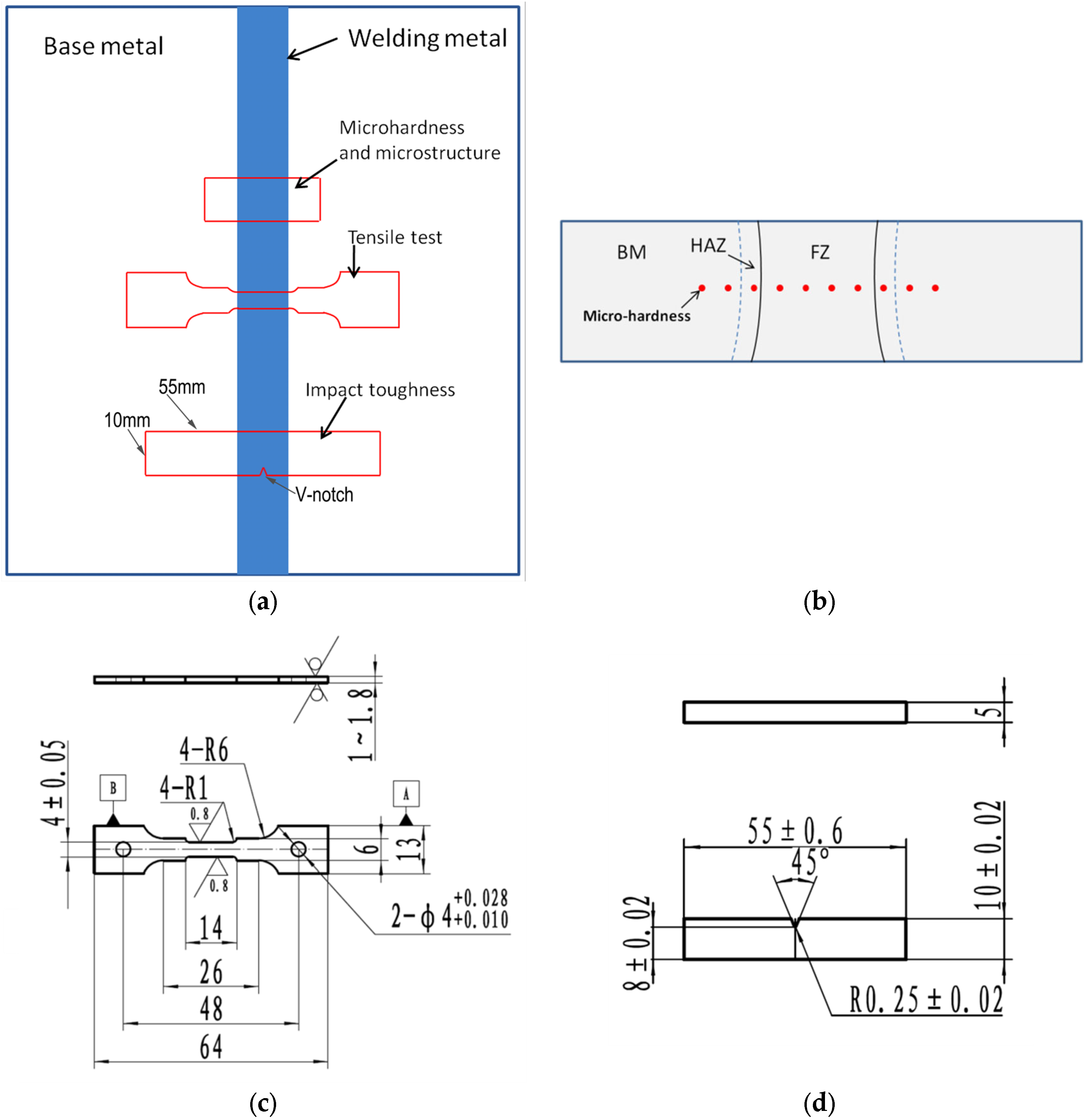
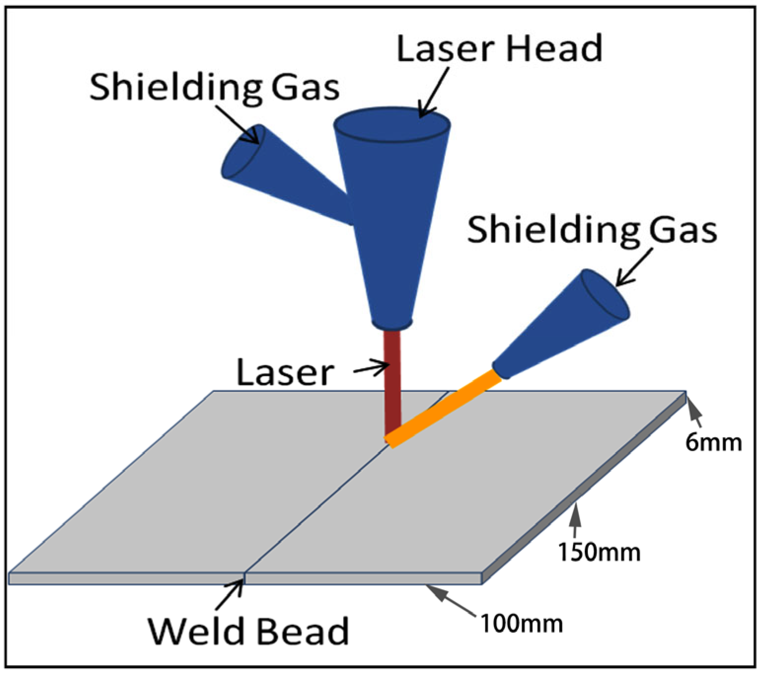
2.1. Welding Material and Method
2.2. Mechanical Property Tests
2.3. Characterization of the Microstructure
3. Results
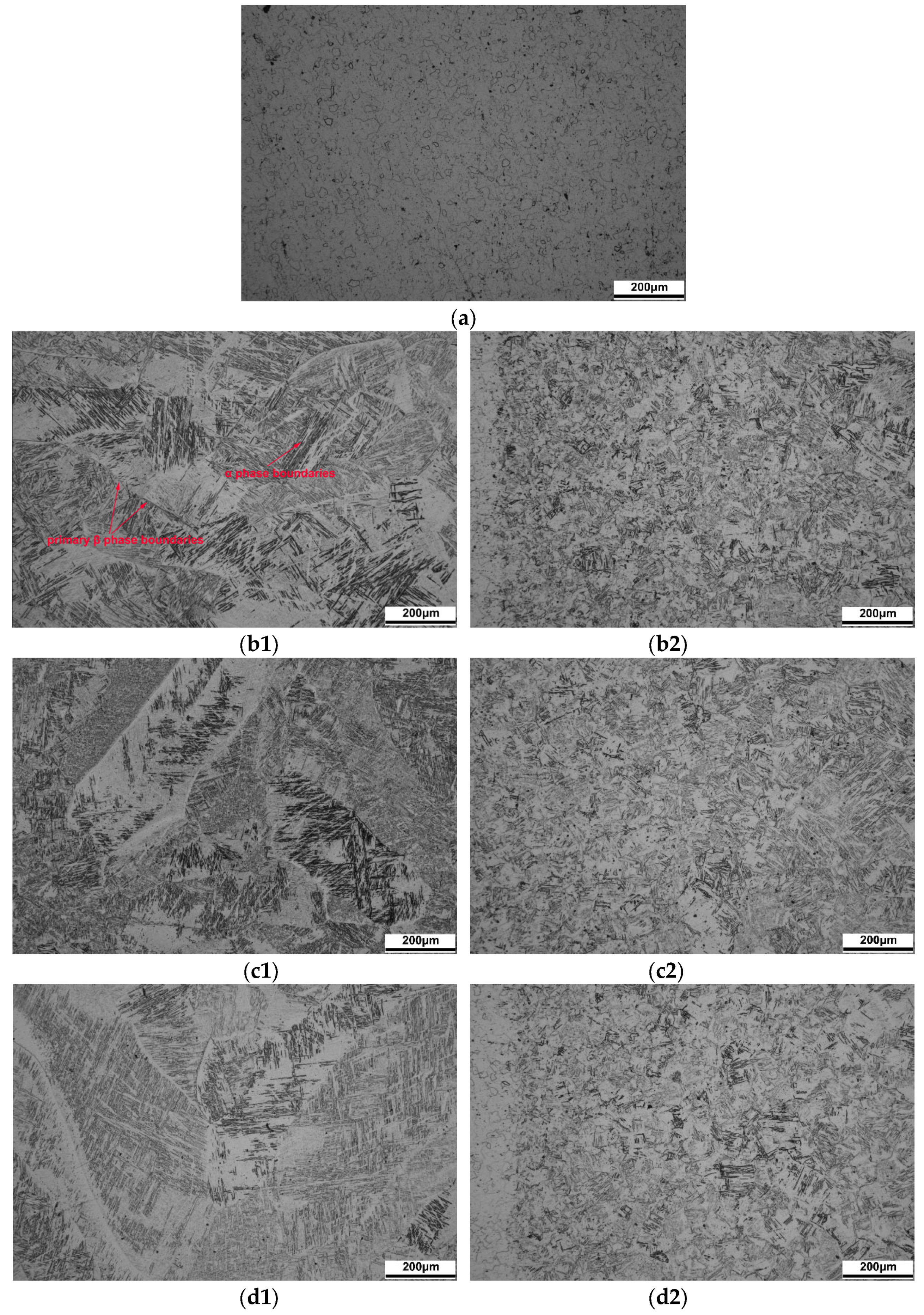
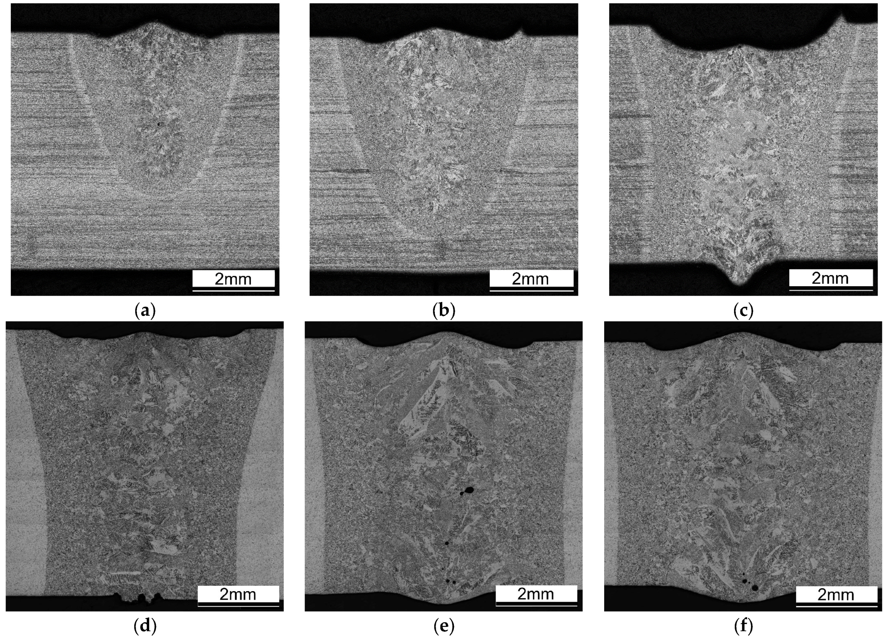
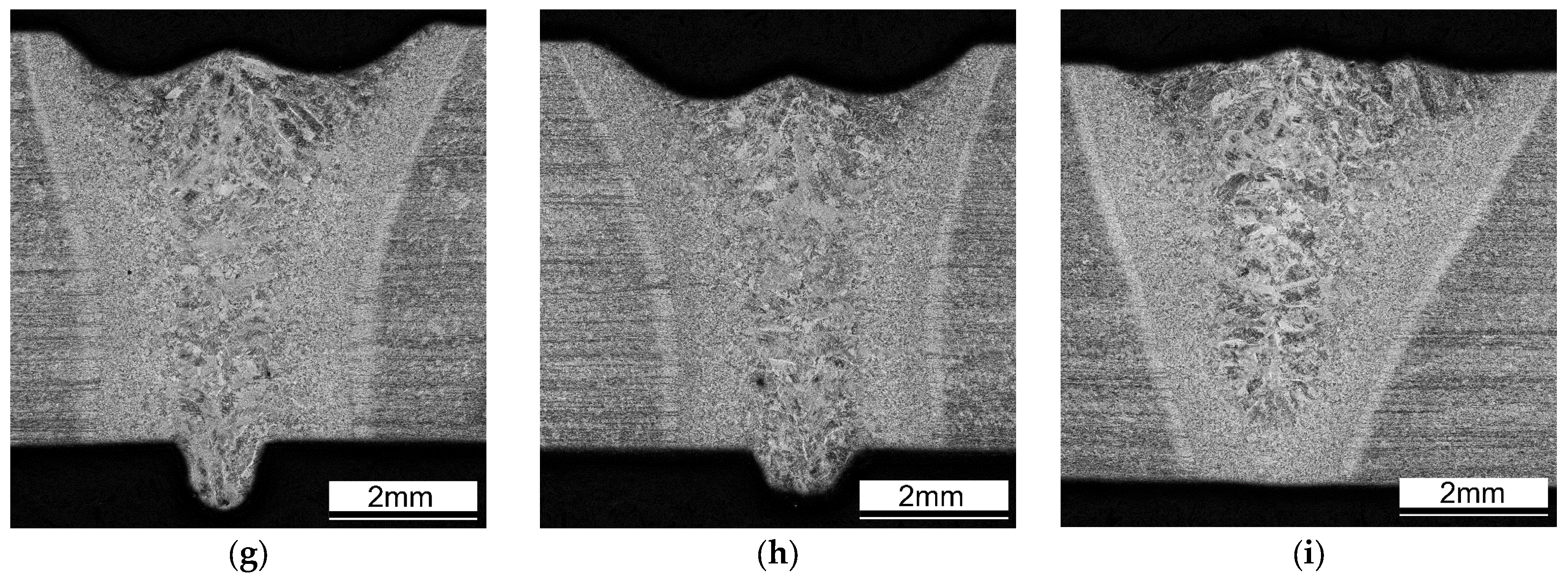
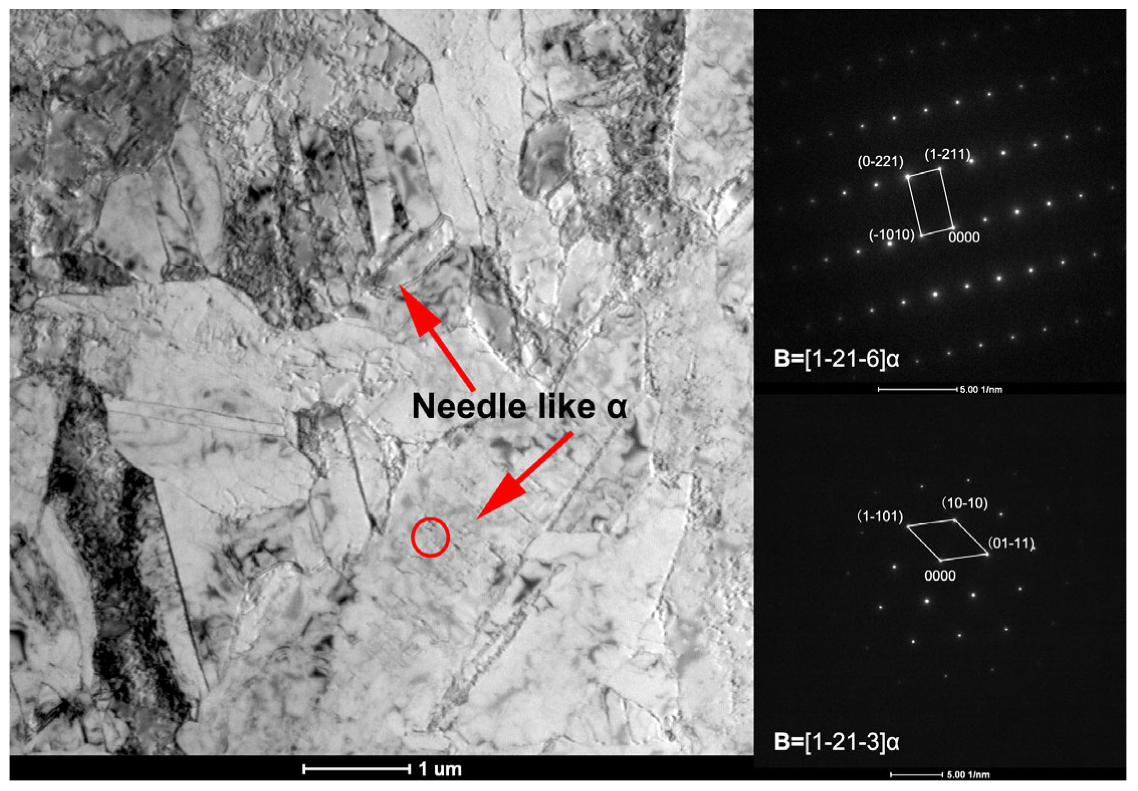
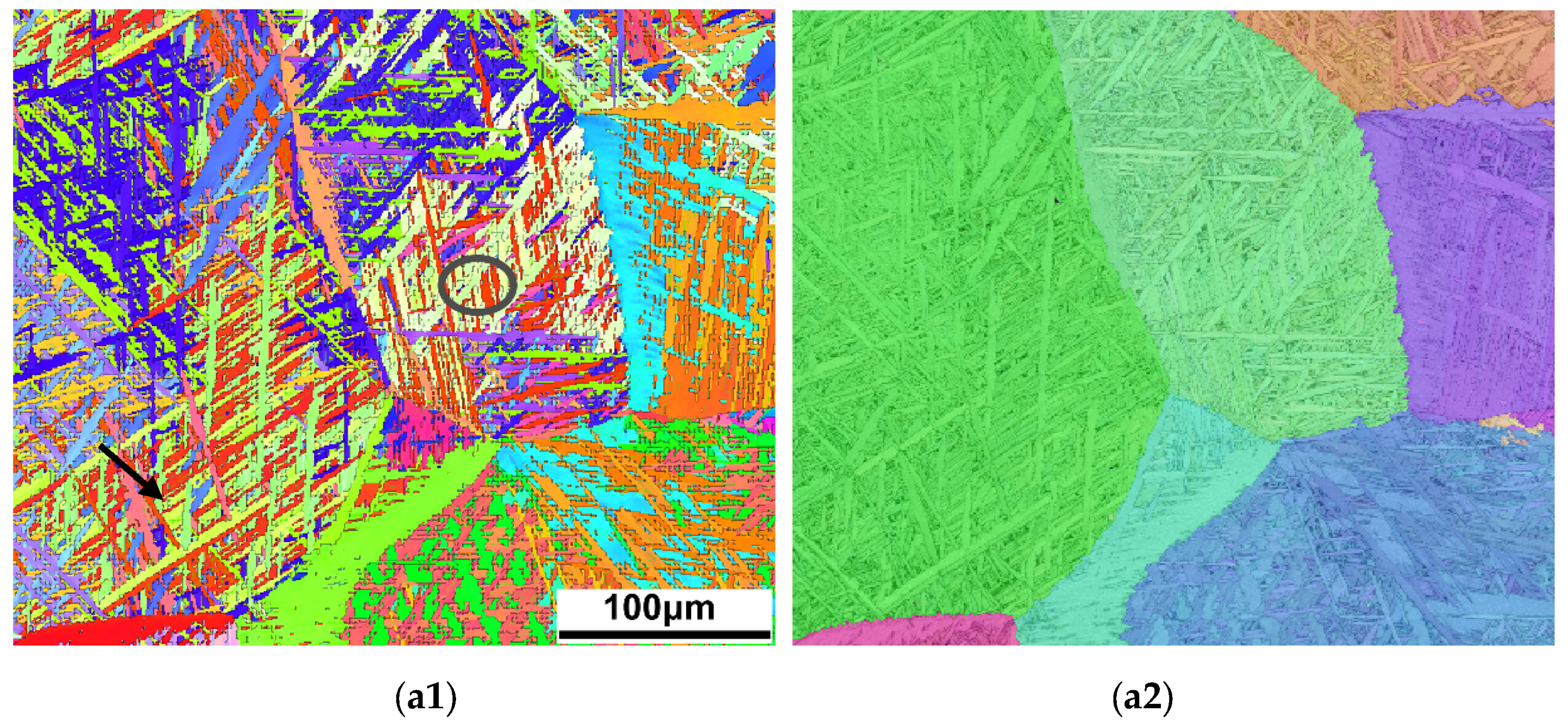
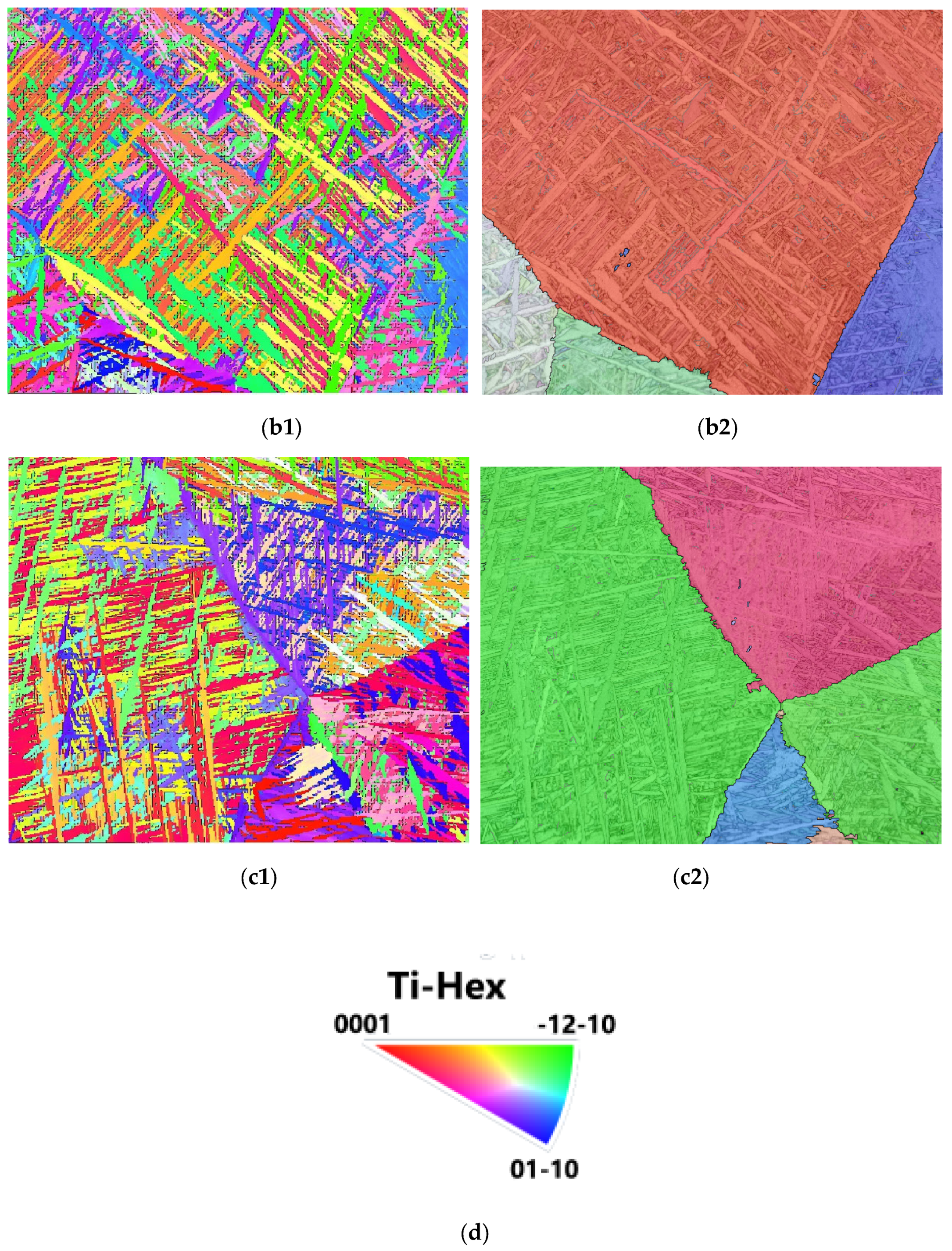
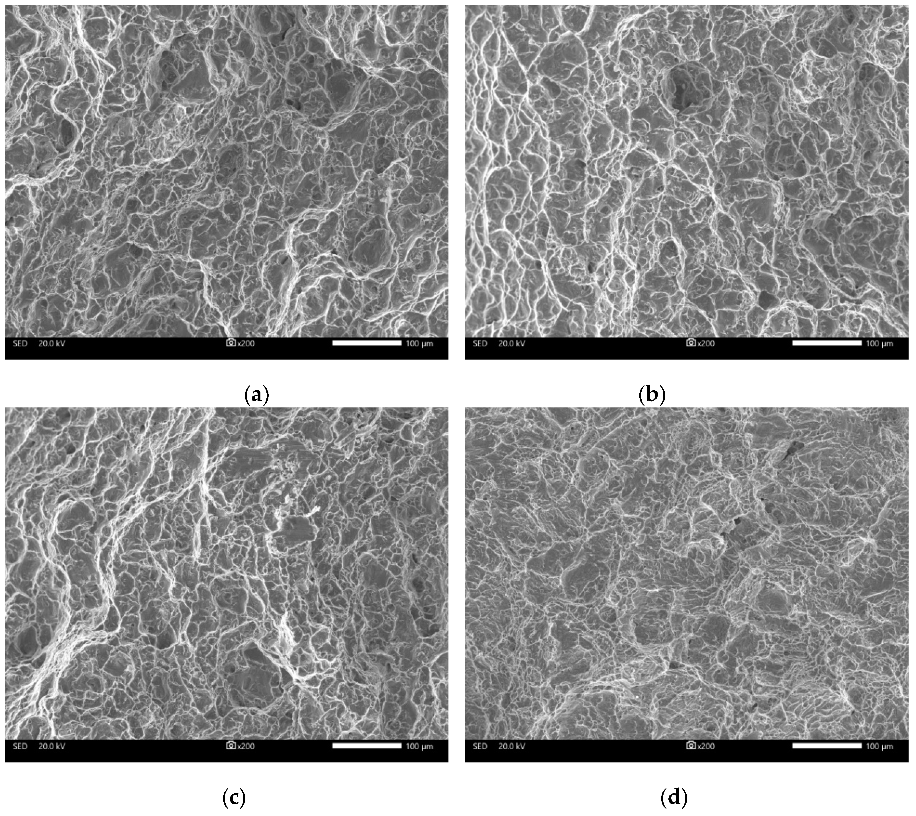
3.1. Microstructure
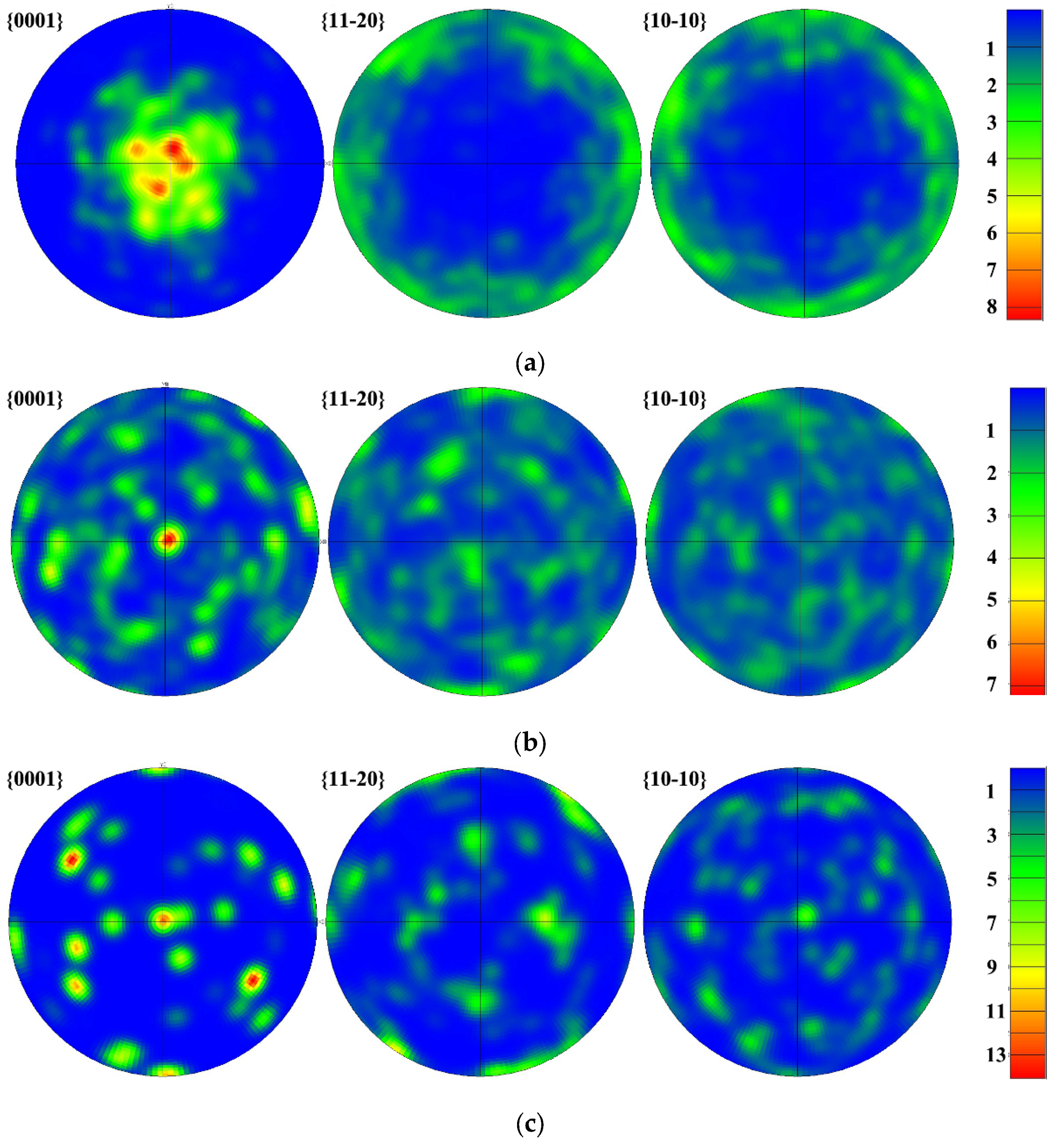
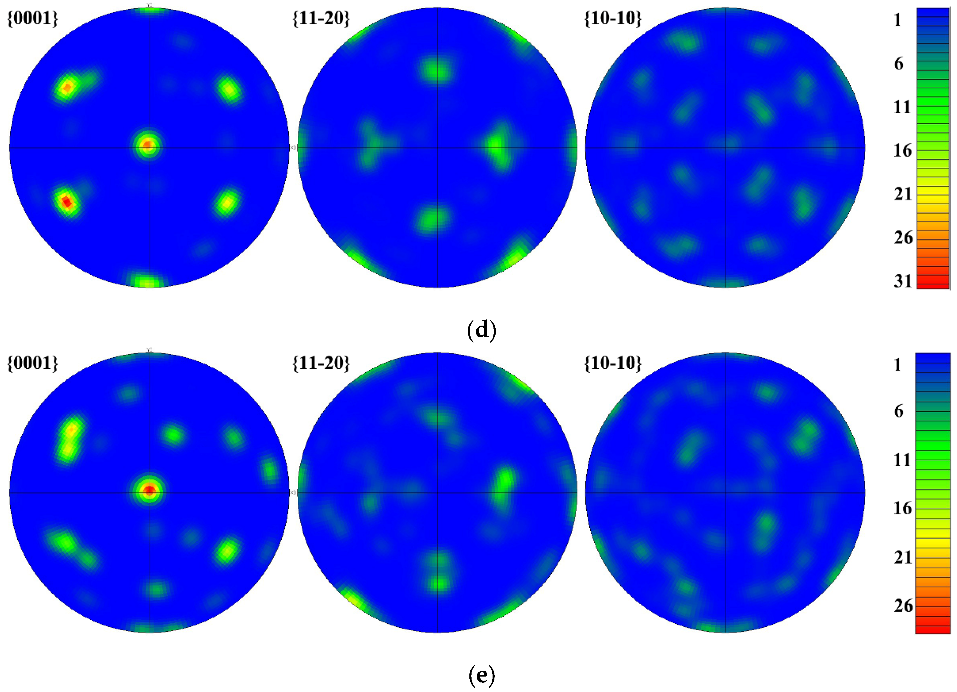
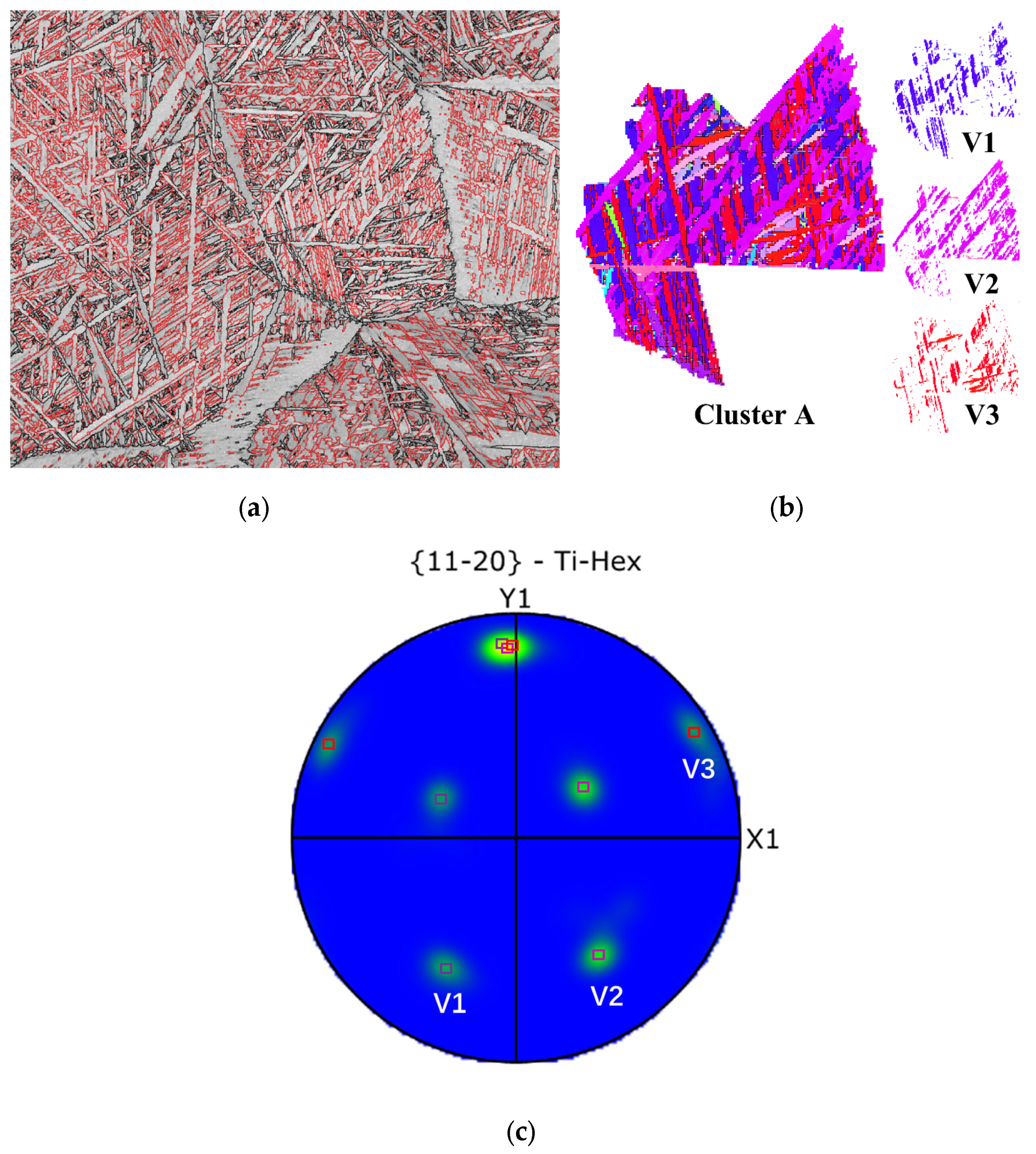
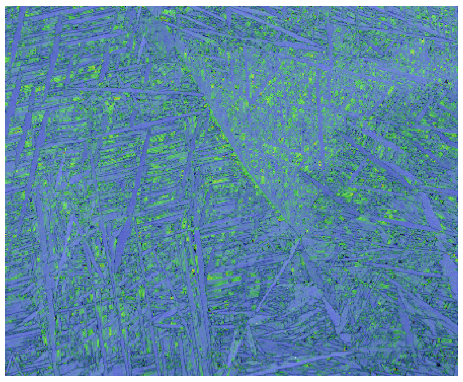
3.2. Texture
3.3. Variant Selection
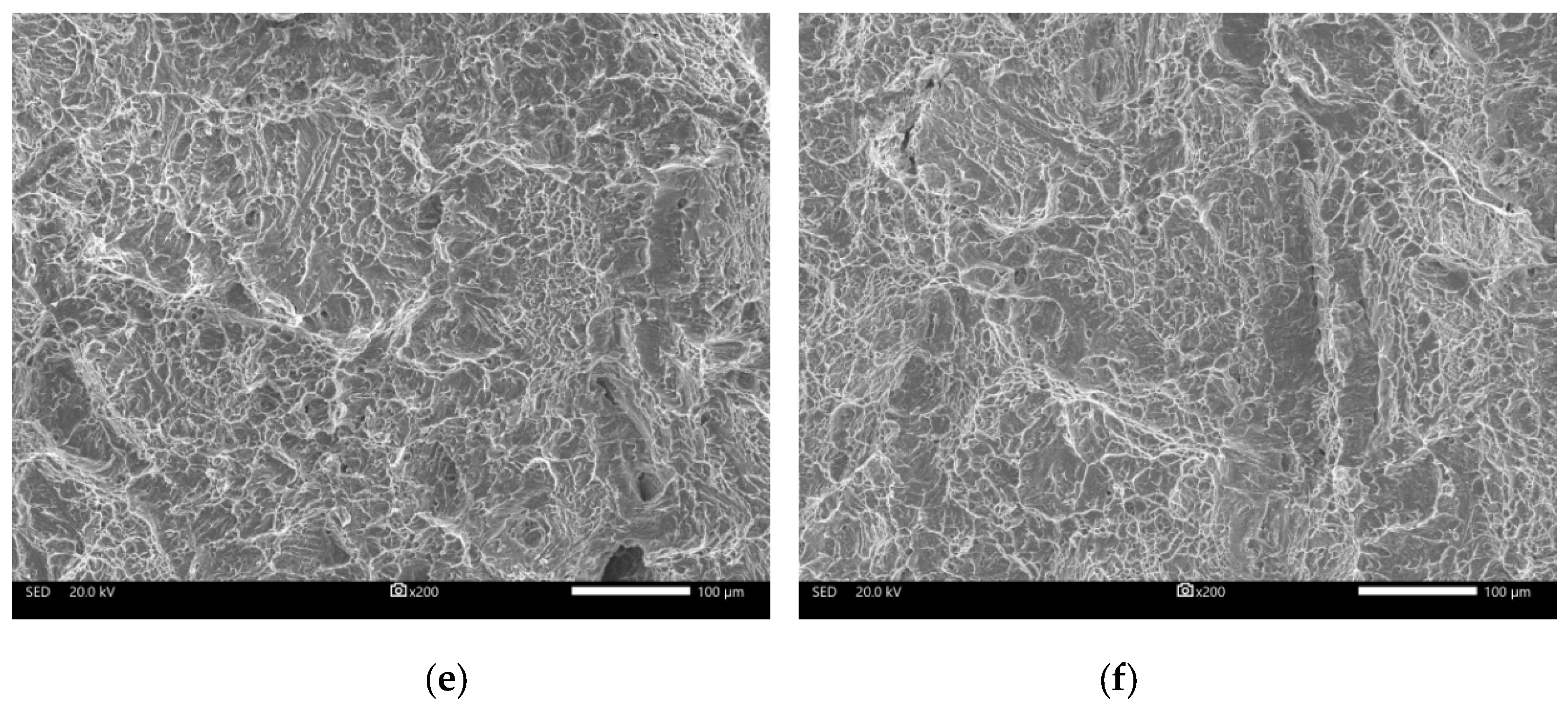
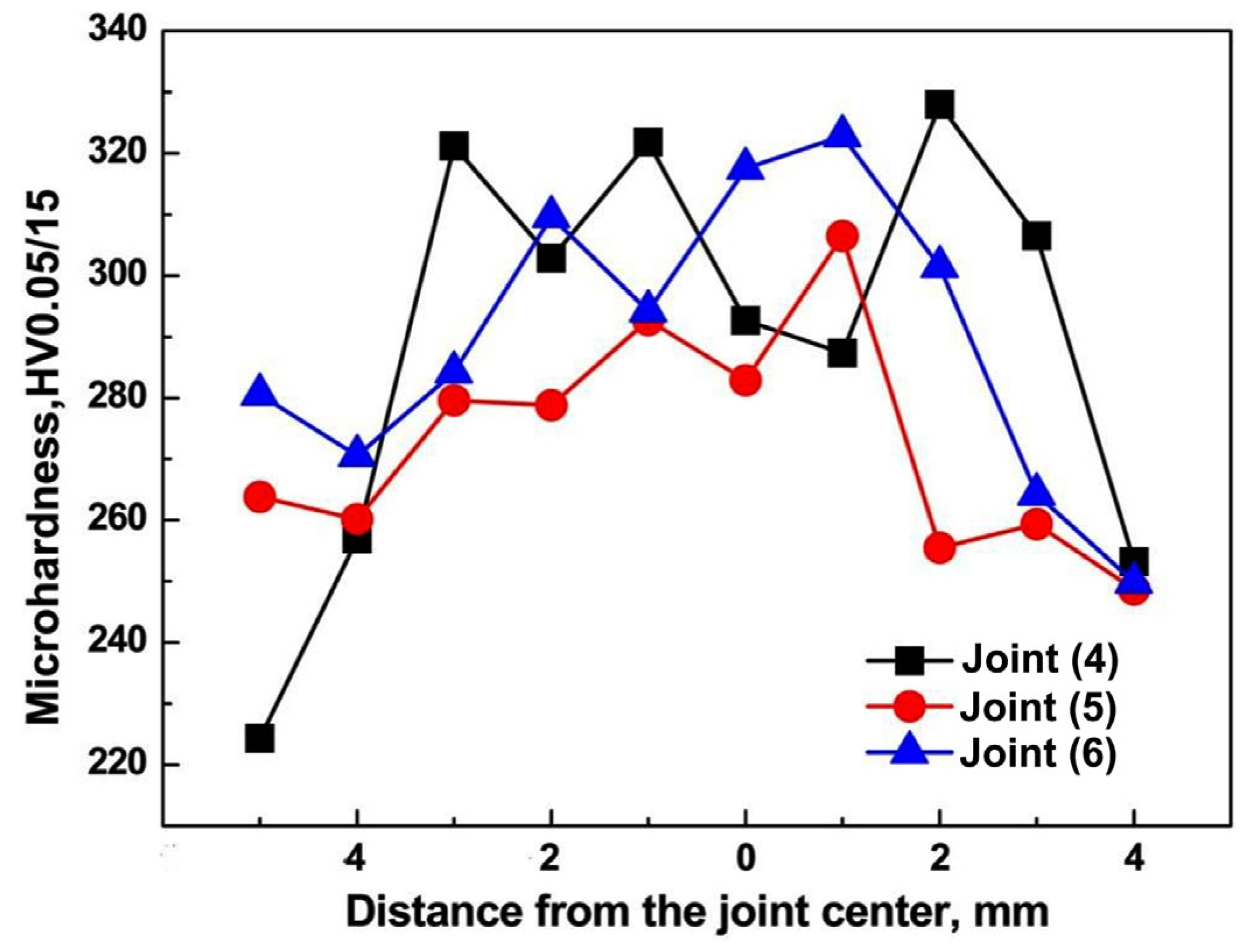
3.4. Mechanical Properties
4. Discussion
4.1. The Weld Pool and the Porosity of the Laser-Welded Ti-4Al-2V Alloy Plate
4.2. Characteristics of the Formation of Variant Clusters
4.3. Relationship among the Laser’s Parameters, Macro- and Microstructures, and Mechanical Properties
5. Conclusions
- A welding speed of 20 mm/s, a defocus distance of −2 mm, and a welding power of 4.7 kW could ensure penetration of the weld. On this basis, increasing the defocus distance to 2 mm or reducing the welding power to 3.2 kW prevented the weld from fully penetrating, but adjusting the welding speed to 25 mm/s could also ensure deep penetration. There were porosity defects inside the weld bead under multiple conditions, especially in the middle and lower parts. There was no significant difference in the microstructure of the FZ among different welding conditions, and all were needle-shaped α martensite.
- The α-variants of the Ti-4Al-2V alloy welds formed by laser welding showed significant selective precipitation characteristics, mainly characterized in the form of Type I clusters, and the formation of <11−20>/60 ° interfaces between the variants within the clusters reduce the interface’s energy. Meanwhile, in order to balance the overall energy of the weld joint, a larger proportion of<11−20>/60 ° interfaces inside the cluster existed, with higher KAM values inside the variant.
- Under different welding conditions, the yield strength and tensile strength of the weld seam were basically similar. The yield strength of the weld joints was slightly lower than that of the BM, while the tensile strength was slightly higher than that of the BM. In addition, when the laser power increased from 4.7 kW to 5.2 kW and the welding speed decreased from 20 mm/s to 15 mm/s, the elongation after fracture decreased by about 40%, which was significantly lower than that of the BM. The micro-Vickers hardness of laser-welded joints was significantly higher than that of the BM, while the impact toughness was much lower.
Author Contributions
Funding
Data Availability Statement
Conflicts of Interest
References
- Chen, J.; Ouyang, Z.; Du, X.; Wei, Y. Weld pool dynamics and joining mechanism in pulse wave laser beam welding of Ti-6Al-4V titanium alloy sheets assembled in butt joint with an air gap. Opt. Laser Technol. 2022, 146, 107558. [Google Scholar] [CrossRef]
- Rominiyi, A.L.; Mashinini, P.M. A critical review of microstructure and mechanical properties of laser welded similar and dissimilar titanium alloy joints. J. Adv. Join. Process. 2024, 9, 100191. [Google Scholar] [CrossRef]
- Liu, J.; Watanabe, I.; Yoshida, K.; Atsuta, M. Joint strength of laser-welded titanium. Dent. Mater. 2022, 18, 143–148. [Google Scholar] [CrossRef] [PubMed]
- Auwal, S.T.; Ramesh, S.; Yusof, F.; Manladan, S.M. A review on laser beam welding of titanium alloys. Int. J. Adv. Manuf. Technol. 2018, 97, 1071–1098. [Google Scholar] [CrossRef]
- Li, G.; Wang, Y.; Liang, Y.; Gao, P.; Liu, X.; Xu, W.; Yang, D. Microstructure and mechanical properties of laser welded Ti-6Al-4V (TC4) titanium alloy joints. Opt. Laser Technol. 2024, 170, 110320. [Google Scholar] [CrossRef]
- Wencel, Z.; Wiewiórowska, S.; Wieczorek, P.; Gontarz, A. Electron beam welding process for Ti6Al-4V titanium alloy. Materials 2023, 16, 5174. [Google Scholar] [CrossRef] [PubMed]
- Liu, H.; Nakata, K.; Zhang, J.X.; Yamamoto, N.; Liao, J. Microstructural evolution of fusion zone in laser beam welds of pure titanium. Mater. Charact. 2012, 65, 1–7. [Google Scholar] [CrossRef]
- Kumar, P.; Sinha, A.N. Effect of heat input in pulsed Nd: YAG laser welding of titanium alloy (Ti6Al4V) on microstructure and mechanical properties. Weld. World 2018, 63, 673–689. [Google Scholar] [CrossRef]
- Fan, H.; Zhou, P.; Li, J.; Huang, J.; Ni, Y.; Hui, Y. Microstructure and mechanical properties of arc zone and laser zone of TC4 titanium alloy laser–TIG hybrid welded joint. Metals 2022, 12, 1854. [Google Scholar] [CrossRef]
- Lu, S.L.; Wang, J.H.; Sun, Y.Y.; Song, T.; Qian, M. Identification of unusual large zones of Category I triple-alpha-variant clusters in additively manufactured Ti-4Al-2V alloy. Scr. Mater. 2022, 212, 114578. [Google Scholar] [CrossRef]
- Stephenson, P.L.; Haghdadi, N.; DeMott, R.; Liao, X.Z.; Ringer, S.P.; Primig, S. Effect of scanning strategy on variant selection in additively manufactured Ti-6Al-4V. Addit. Manuf. 2020, 36, 101581. [Google Scholar] [CrossRef]
- Farabi, E.; Hodgson, P.D.; Rohrer, G.S.; Beladi, H. Five-parameter intervariant boundary characterization of martensite in commercially pure titanium. Acta Mater. 2018, 154, 147–160. [Google Scholar] [CrossRef]
- Shi, R.; Dixit, V.; Viswanathan, G.B.; Fraser, H.L.; Wang, Y. Experimental assessment of variant selection rules for grain boundary in titanium alloys. Acta Mater. 2016, 102, 197–211. [Google Scholar] [CrossRef]
- Lee, J.Y.; Ko, H.S.; Yoo, C.D. Mechanism of keyhole formation and stability in stationary laser welding. J. Phys. D Appl. Phys. 2002, 35, 1570. [Google Scholar] [CrossRef]
- Cho, J.H.; Farson, D.F.; Milewski, J.O.; Hollis, K.J. Weld pool flows during initial stages of keyhole formation in laser welding. J. Phys. D. Appl. Phys. 2009, 42, 175502. [Google Scholar] [CrossRef]
- Shen, L.; Chen, Y.; Zhu, H.; Lei, Y.; Qiu, C. Ti6Al4V alloy remelting by modulation laser: Deep penetration, high compactness and metallurgical bonding with matrix. Micromachines 2022, 13, 1107. [Google Scholar] [CrossRef]
- Zhao, C.; Parab, N.D.; Li, X.; Fezzaa, K.; Tan, W.; Rollett, A.D.; Sun, T. Critical instability at moving keyhole tip generates porosity in laser melting. Science 2020, 370, 1080–1086. [Google Scholar] [CrossRef]
- Li, D.; Yu, Z.; Tang, W.; Deng, J. A new α Ti alloy (Ti-4Al-2V) for marine engineering. J. Mater. Sci. Technol. 2001, 17, 77–78. [Google Scholar]
- Liu, Y.Z.; Zu, X.T.; Qiu, S.Y.; Huang, X.Q. Surface characteristics and corrosion behavior of Ti-4Al-2V alloy implanted with Al and Nb. In Materials Science Forum; Trans Tech Publications Ltd.: Freienbach, Switzerland, 2007; Volume 561, pp. 2443–2446. [Google Scholar]
- Omidbakhsh, F.; Ebrahimi, A.R.; Mousavi, S.H.; Khosroshahi, R.A.; Nazarpour, S. Effect of oxygen boost diffusion treatment on fatigue behavior of Ti–4Al–2V alloy. Surf. Coat. Technol. 2011, 205, 2954–2963. [Google Scholar] [CrossRef]
- Rodchenkov, B.S.; Kozlov, A.V.; Kuznetsov, Y.G.; Kalinin, G.M.; Strebkov, Y.S. Irradiation behavior of Ti–4Al–2V (ΠT-3B) alloy for ITER blanket modules flexible attachment. J. Nucl. Mater. 2007, 367, 1312–1315. [Google Scholar] [CrossRef]
- Fu, C.; Wang, Y.; He, S.; Zhang, C.; Jing, X. Microstructural characterization and mechanical properties of TIG weld joint made by forged Ti–4Al–2V alloy. Mater. Sci. Eng. A 2021, 821, 141604. [Google Scholar] [CrossRef]
- Wang, F.; Sun, Z.; Liu, Z.; Hai, M.; Wu, Y.; Zhang, J.; Luo, R. Performance analysis on welded joints made of TC4/TA17 dissimilar titanium alloys. Ocean. Eng. 2024, 294, 116758. [Google Scholar] [CrossRef]
- Liu, F.; Chen, Y.; Li, L.; Wang, C.; Wang, Q.; Liu, Y. Influence of welded pores on fatigue behavior of TC17 titanium alloy welded joints subjected to gigacycle regime at room and high temperatures. J. Mater. Sci. Technol. 2024, 178, 1–21. [Google Scholar] [CrossRef]
- Lu, S.L.; Todaro, C.J.; Sun, Y.Y.; Song, T.; Brandt, M.; Qian, M. Variant selection in additively manufactured alpha-beta titanium alloys. J. Mater. Sci. Technol. 2022, 113, 14–21. [Google Scholar] [CrossRef]
- Matsunawa, A.; Kim, J.D.; Seto, N.; Mizutani, M.; Katayama, S. Dynamics of keyhole and molten pool in laser welding. J. Laser Appl. 1998, 10, 247–254. [Google Scholar] [CrossRef]
- Fabbro, R.; Chouf, K. Keyhole modeling during laser welding. J. Appl. Phys. 2000, 87, 4075–4083. [Google Scholar] [CrossRef]
- Kobryn, P.A.; Moore, E.H.; Semiatin, S.L. The effect of laser power and traverse speed on microstructure, porosity, and build height in laser-deposited Ti-6Al-4V. Scr. Mater. 2000, 43, 299–305. [Google Scholar] [CrossRef]
- Kasperovich, G.; Haubrich, J.; Gussone, J.; Requena, G. Correlation between porosity and processing parameters in TiAl6V4 produced by selective laser melting. Mater. Des. 2016, 105, 160–170. [Google Scholar] [CrossRef]
- Fang, Y.; Jiang, X.; Song, T.; Mo, D.; Luo, Z. Pulsed laser welding of Ti-6Al-4V titanium alloy to AISI 316L stainless steel using Cu/Nb bilayer. Mater. Lett. 2019, 244, 163–166. [Google Scholar] [CrossRef]
- Su, R.; Li, H.; Chen, H.; Wang, H.; Wang, W.; Wang, D.; Gao, J. Stability analysis and porosity inhibition mechanism of oscillating laser-arc hybrid welding process for medium-thick plate TC4 titanium alloy. Opt. Laser Technol. 2024, 174, 110569. [Google Scholar] [CrossRef]
- Panwisawas, C.; Perumal, B.; Ward, R.M.; Turner, N.; Turner, R.P.; Brools, J.W.; Basoalto, H.C. Keyhole formation and thermal fluid flow-induced porosity during laser fusion welding in titanium alloys: Experimental and modelling. Acta Mater. 2017, 126, 251–263. [Google Scholar] [CrossRef]
- Yu, J.; Cai, C.; Xie, J.; Chen, Z.; Chen, H. Keyhole stability, arc behavior, and molten pool flow in narrow-gap oscillating laser-arc hybrid welding of titanium alloy. Int. J. Heat Mass Transf. 2024, 220, 124922. [Google Scholar] [CrossRef]
- Wang, S.C.; Aindow, M.; Starink, M.J. Effect of self-accommodation on α/α boundary populations in pure titanium. Acta Mater. 2003, 51, 2485–2503. [Google Scholar] [CrossRef]
- Beladi, H.; Qi, C.; Rohrer, G.S. Variant selection and intervariant crystallographic planes distribution in martensite in a Ti–6Al–4V alloy. Acta Mater. 2014, 80, 478–489. [Google Scholar] [CrossRef]


| Ti | Al | V | C | O | N | Zr | Fe | Si | Co |
|---|---|---|---|---|---|---|---|---|---|
| Bal. | 4.90 | 2.30 | 0.01 | 0.09 | 0.01 | <0.10 | <0.05 | <0.01 | <0.01 |
| Laser Power, kW | Welding Speed, mm/s | Defocus Distance, mm | |
|---|---|---|---|
| Joint (1) | 2.2 | 20 | −2 |
| Joint (2) | 3.2 | 20 | −2 |
| Joint (3) | 4.2 | 20 | −2 |
| Joint (4) | 4.7 | 20 | −2 |
| Joint (5) | 5.2 | 20 | −2 |
| Joint (6) | 4.7 | 15 | −2 |
| Joint (7) | 4.7 | 25 | −2 |
| Joint (8) | 4.7 | 20 | 0 |
| Joint (9) | 4.7 | 20 | 2 |
| Yield Strength, MPa | Tensile Strength, MPa | Rupture Elongation, % | Charpy Impact Toughness, J | |
|---|---|---|---|---|
| BM | 638 | 697 | 23 | 80.7 ± 3.2 |
| Joint (4) | 625 ± 7 | 729 ± 4 | 11.2 ± 1.2 | 45.4 ± 9.7 |
| Joint (5) | 615 ± 3 | 722 ± 9 | 7.2 ± 0.1 | 48.1 ± 5.3 |
| Joint (6) | 601 ± 9 | 720 ± 3 | 7.7 ± 0.2 | 36.6 ± 2.0 |
| Variant | Burgers Orientation Relationship (BOR) | Rotation Angle/Axis from V1 |
|---|---|---|
| V1 | (1−10)β//(0001)α; [111]β//[11-20]α | / |
| V2 | (10−1)β//(0001)α; [111]β//[11-20]α | 60°/[1 1 −2 0] |
| V3 | (01−1)β//(0001)α; [111]β//[11-20]α | 60°/[1 1 −2 0] |
| V4 | (110)β//(0001)α; [-111]β//[11-20]α | 90°/[1 −2.38 1.38 0] |
| V5 | (101)β//(0001)α; [-111]β//[11-20]α | 63.26°/[−10 5 5 -3] |
| V6 | (01−1)β//(0001)α; [-111]β//[11-20]α | 60.83°/[−1.377 −1 2.377 0.359] |
| V7 | (110)β//(0001)α; [1-11]β//[11-20]α | 90°/[1 −2.38 1.38 0] |
| V8 | (10−1)β//(0001)α; [1-11]β//[11-20]α | 60.83°/[−1.377 −1 2.377 0.359] |
| V9 | (011)β//(0001)α; [1-11]β//[11-20]α | 63.26°/[-10 5 5 -3] |
| V10 | (1−10)β//(0001)α; [11-1]β//[11-20]α | 10.53°/[0 0 0 1] |
| V11 | (101)β//(0001)α; [11-1]β//[11-20]α | 60.83°/[−1.377 −1 2.377 0.359] |
| V12 | (011)β//(0001)α; [11-1]β//[11-20]α | 60.83°/[−1.377 −1 2.377 0.359] |
Disclaimer/Publisher’s Note: The statements, opinions and data contained in all publications are solely those of the individual author(s) and contributor(s) and not of MDPI and/or the editor(s). MDPI and/or the editor(s) disclaim responsibility for any injury to people or property resulting from any ideas, methods, instructions or products referred to in the content. |
© 2024 by the authors. Licensee MDPI, Basel, Switzerland. This article is an open access article distributed under the terms and conditions of the Creative Commons Attribution (CC BY) license (https://creativecommons.org/licenses/by/4.0/).
Share and Cite
Zhu, Y.; Lu, L.; Zhang, C.; Yuan, J.; Fu, C.; Wang, L. Microstructure, Variant Selection, and Mechanical Properties of Laser-Welded Ti-4Al-2V Joints. Metals 2024, 14, 405. https://doi.org/10.3390/met14040405
Zhu Y, Lu L, Zhang C, Yuan J, Fu C, Wang L. Microstructure, Variant Selection, and Mechanical Properties of Laser-Welded Ti-4Al-2V Joints. Metals. 2024; 14(4):405. https://doi.org/10.3390/met14040405
Chicago/Turabian StyleZhu, Yonghui, Lili Lu, Chenlu Zhang, Jun Yuan, Chao Fu, and Lu Wang. 2024. "Microstructure, Variant Selection, and Mechanical Properties of Laser-Welded Ti-4Al-2V Joints" Metals 14, no. 4: 405. https://doi.org/10.3390/met14040405
APA StyleZhu, Y., Lu, L., Zhang, C., Yuan, J., Fu, C., & Wang, L. (2024). Microstructure, Variant Selection, and Mechanical Properties of Laser-Welded Ti-4Al-2V Joints. Metals, 14(4), 405. https://doi.org/10.3390/met14040405