Article

Effect of Copper Content on the Microstructure and Properties of the Sintered Porous Aluminum Wick

School of Materials Science and Engineering, Central South University, Changsha 410083, China
*
Author to whom correspondence should be addressed.
Metals 2024, 14(4), 386; https://doi.org/10.3390/met14040386
Submission received: 1 March 2024 / Revised: 22 March 2024 / Accepted: 25 March 2024 / Published: 26 March 2024
(This article belongs to the Special Issue High-Performance Powder Metallurgy Structural Materials)

Abstract

:
Porous aluminum has been widely used as a wick, an electrode, and in other products, due to its advantages of a light weight, pore uniformity, and corrosion resistance. However, the dense alumina layer on the surface of Al powder hinders its densification during sintering. In this paper, porous aluminum was prepared via loose powder sintering with the addition of Cu as a sintering aid. The effects of Cu content on the microstructure and wick properties of the porous aluminum were investigated. The results showed that, with increasing Cu content, the porosity and capillary properties of porous Al decreased, while the compressive strength improved. The optimal Cu content was determined to be 3 wt.% and the prepared porous Al has a porosity of 47.5%, plateau stress of 11.82 MPa, and capillary characteristic parameter of 6.72 × 10⁻⁸ N, meeting the requirements for wicks in heat pipes. These findings contribute to the demand for the lightweight design of heat pipes for aerospace applications.

1. Introduction

Vapor chambers, as a promising thermal management device with high heat dissipation efficiency, a controllable shape, and good temperature uniformity, have garnered significant attention in various applications, including aerospace, electronic components, and home appliances [1,2,3,4]. They consist of a container, capillary wick, and working fluid [5]. As the key component of vapor chambers or other heat pipes, the capillary wick, with a porous structure, provides a necessary driving force for the working fluid and plays a crucial role in determining the heat dissipation efficiency [6].
The performance of a capillary wick depends on many factors, such as materials, porous structures, preparation method, etc. [7,8,9,10]. Commonly available materials for wicks include copper, aluminum, nickel, and carbon fiber [11,12,13,14]. With the urgent demand for a lightweight design and low cost for the equipment and components in many fields, such as aerospace and automotive industries, the porous Al wick is increasingly attracting widespread attention. It not only combines the advantages of the high thermal conductivity of Cu and a low density of carbon fiber, but also has lower costs and better corrosion resistance [15,16].
Currently, Al capillary wicks are fabricated through various methods, including chemical etching, laser etching, ultrasonic modified etching, compression sintering, and discharge plasma sintering [17,18,19,20,21]. However, the etching process, employing chemical reaction, high-temperature cutting, or ultrasonic cavitation to process fine grooves on an Al flat plate, is complex and costly to operate and prepares a capillary wick with a low capillary force. Discharge plasma sintering forms the pore structure by heating the particles with an instantaneous high-temperature plasma, which is expensive and makes it difficult to control the pore structure of the wick. In addition, compression-sintered porous Al wicks utilize external pressure to destroy the oxide film to promote sintering, but the powder is rearranged by force, changing the filling density. Furthermore, the pore uniformity and connectivity of the samples are poor, and their shapes are simple.
In contrast, the loose powder sintering method represents a traditional and well-established technology that naturally forms interconnected pores within the powders. This method allows for the formation of a certain level of strength after establishing the sintering neck while minimally impacting the pore structure and has been successfully applied in the preparation of porous titanium and porous nickel [22,23,24]. It can be foreseen that a porous Al wick prepared using loose powder sintering will offer advantages such as controllable pores, few impurities, adjustable sample shapes, and cost-effectiveness. Nevertheless, Al exhibits strong reactivity and tends to form a dense and chemically stable oxide film on its surface, which poses a challenge in the loose sintering of Al powder to establish an effective sintering neck, as the powder does not have any destructive mechanism to act on the alumina film, such as pressure deformation in compression sintering and plasma activation in discharge plasma sintering [25,26,27,28].
In order to improve the sintering of Al powder, some additives, such as magnesium, silicon, and tin, have been introduced [29,30,31]. These additives can disrupt the surface oxide film of the powder by reacting with the Al, improving its sintering properties and strength. In the preparation of some Al alloys or Cu alloys, it has been found that Cu and Al are prone to forming many intermediate phases under certain conditions, indicating that the addition of Cu may also be beneficial for the sintering of Al powder [32]. However, there are relatively few literature reports on this topic, which mainly focus on the strengthening of Cu for Al alloys, with fewer studies on the use of Cu content for the formation of porous Al wicks.
In this paper, a porous Al wick was prepared using loose sintering with Cu as a sintering aid, and the effects of Cu content on the pore structure, mechanical properties, and capillary properties of porous Al were systematically investigated.

2. Experimental Procedure

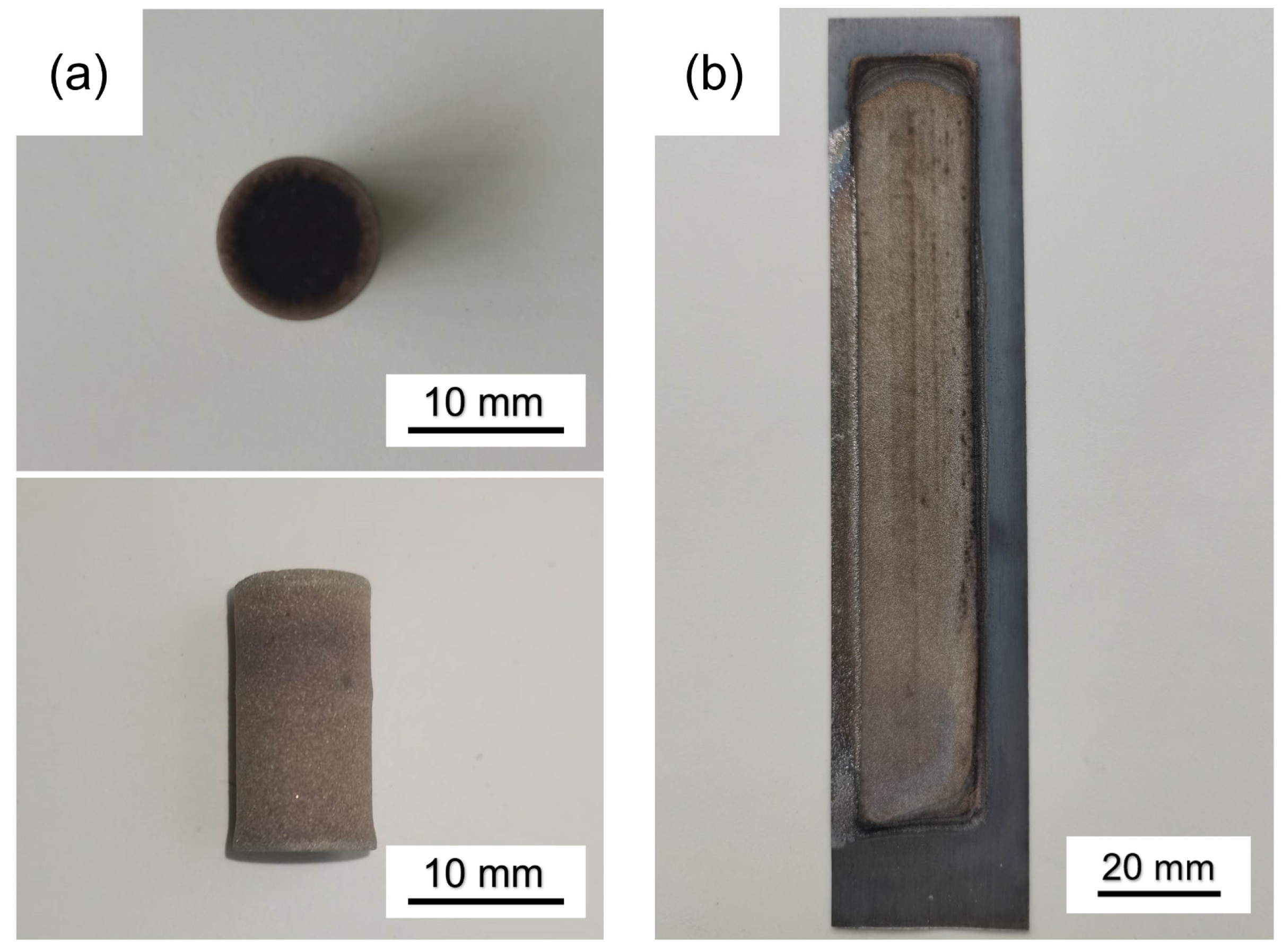
2.1. Experimental Process

Spherical Al powder (purity: 99.5%; particle size: 54–76 μm) and dendritic Cu powder (purity: 99.8%; particle size: <30.8 μm) prepared via the electrolytic reduction method were selected as raw materials for the experiments (Figure 1). First, the Al powder and Cu powder were weighed according to the designed formula; then, 5 mm zirconia balls with a ball–powder weight ratio of 1:1 were added and mixed in a mixer at 120 rpm for 2 h, with a 5 min stop for every 30 min of mixing during this period. Subsequently, the powder was sieved to remove small balls and the mixed powders were filled into graphite molds (120 × 20 × 1 mm or Φ10 × 20 mm). During filling, the mold was steadily tapped to ensure the even distribution and filling of the powder. Next, the excess powder was scraped off, the flake sample was covered with an Al plate (150 × 30 × 0.5 mm), and the device was inverted during the sintering process to ensure that the powder was bonded to the Al plate. Finally, the mold and sample were placed into a tube furnace and heated to 600 °C at a heating rate of 5 °C/min for 60 min to prepare porous Al specimens based on the Al melting point and previous studies [12]. A flowing hydrogen atmosphere with high purity was used in the chamber to prevent the oxidation of metal powder during sintering. To minimize experimental randomness, three samples of each type were made, and the data were averaged. The weight of the final sintered Column Sample was maintained at 2.55 g with dimensions of Φ9.92 × 19.5 mm, and the flake sample weighed in at 3.5 g with dimensions of 118.3 × 19.18 × 0.94 mm. The appearances of the sample are shown in Figure 2.

2.2. Characterization

2.2.1. Characterization of Porous Al Wick

The porosities of the sintered specimens were measured by a hydrometer (DE-120M, Daho Meter, Dongguan, China) based on Archimedes’ principle. The microstructure and composition of the sintered samples and the micromorphology of the powders were observed with a scanning electron microscope (SEM, MIRA3, TESCAN, Brno, Czech Republic). The compressive strength was tested using the electronic universal testing machine (DDL-300, Sinotest Equipment, Changchun, China), with Φ6 mm × 9 mm specimens, at a loading rate of 2 mm/min. The phase composition of the sintered specimen was analyzed by an X-ray diffractometer (XRD, D/Max2500, Rigaku, Tokyo, Japan) with Cu-Kα radiation (λ = 0.154 nm).

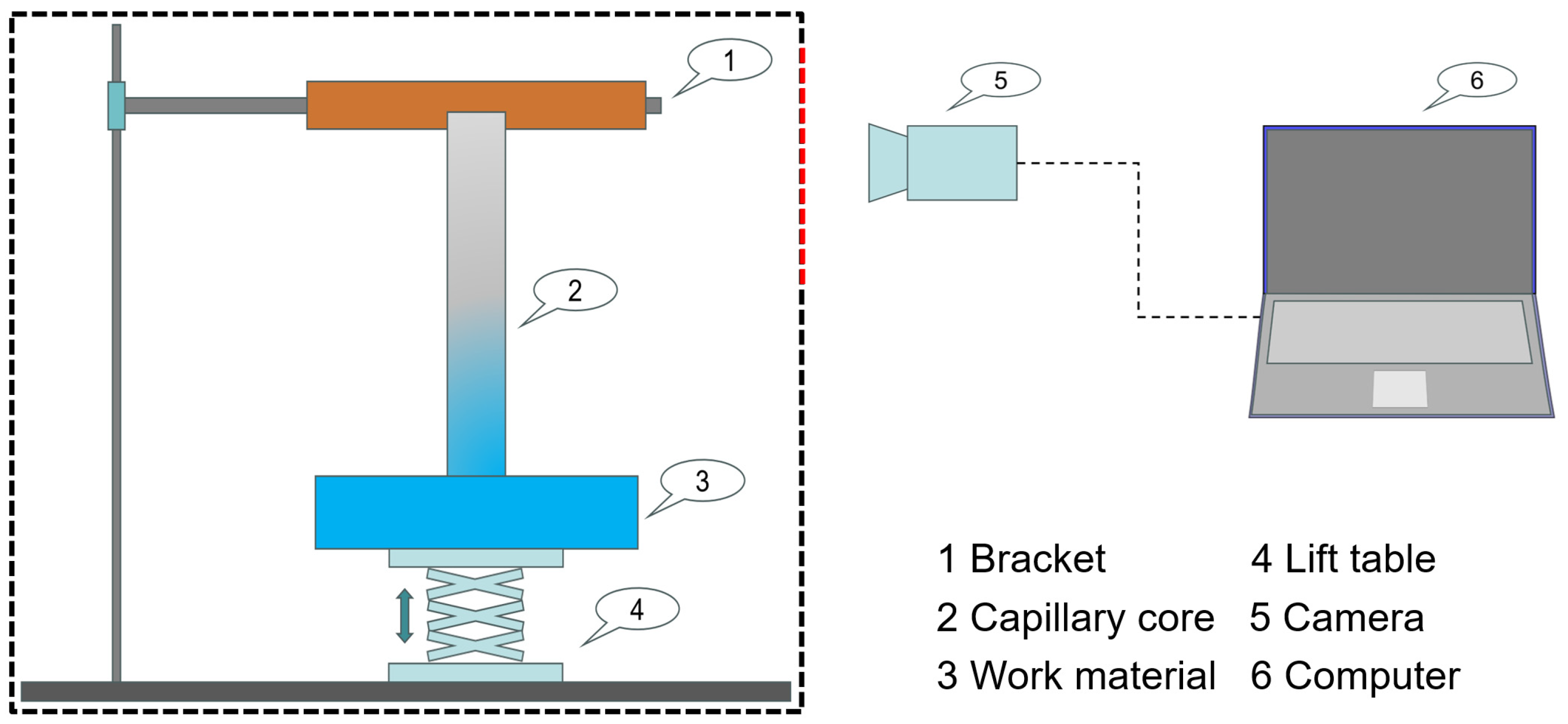
2.2.2. Capillary Rise Experiments

Figure 3 shows the capillary pumping testing device. The testing device consisted of a capillary pumping testing part, mechanical lifting part, and data acquisition part. The samples were simultaneously dipped into the fluid reservoir, and the fluid spontaneously rose along the wicks. The fluid level of the reservoir was thought to be constant during the capillary rise process due to the very small amount of fluid absorbed by the wicks [33]. Then, a video camera was used to record the height of the rise in the working fluid to obtain a time–height curve.
During the capillary rise processes, according to the balance of momentum, the capillary pressure is equal to the pressure loss, which is composed of the viscous friction loss expressed by Darcy’s law and the hydrostatic pressure generated by gravity, as given by Equation (1) [34]:
P c = μ ε K h d h d t + ρ g h
where μ is the viscosity of the work material, ρ is the density of the work material, ε is the porosity of the capillary core, K is the permeability, t is the time, h is the capillary suction height of the work material overcoming the force of gravity, d h d t is the suction velocity of the capillary core, and g is the acceleration of the force of gravity. From Equation (1), the capillary performance parameter is determined by the capillary rise height h, capillary rising velocity d h d t , and permeability K, with the known viscosity of the working fluid and porosity of the wick. The rise velocity, d h d t , can be obtained from the derivative of the curve of capillary rise height versus time [35]. Rearranging Equation (1) yields the following:
P c · K . 1 h ρ g K = μ ε d h d t
From Equation (2), a best linear fitting can be performed with the sets of 1 h and d h d t from the experiments, and the capillary performance parameter ∆Pc·K can be determined from the slope of this fitting line.

3. Results and Discussion

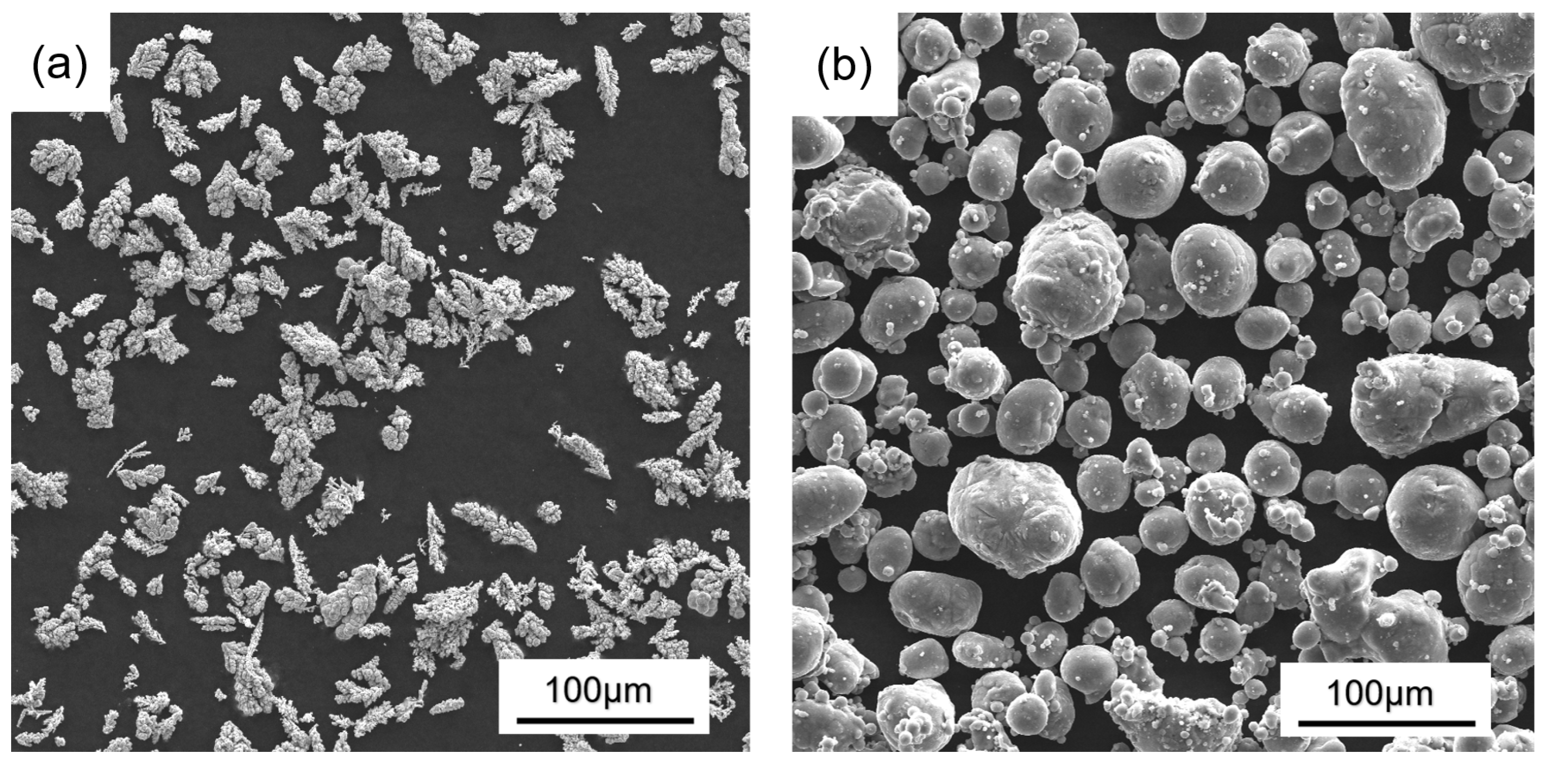
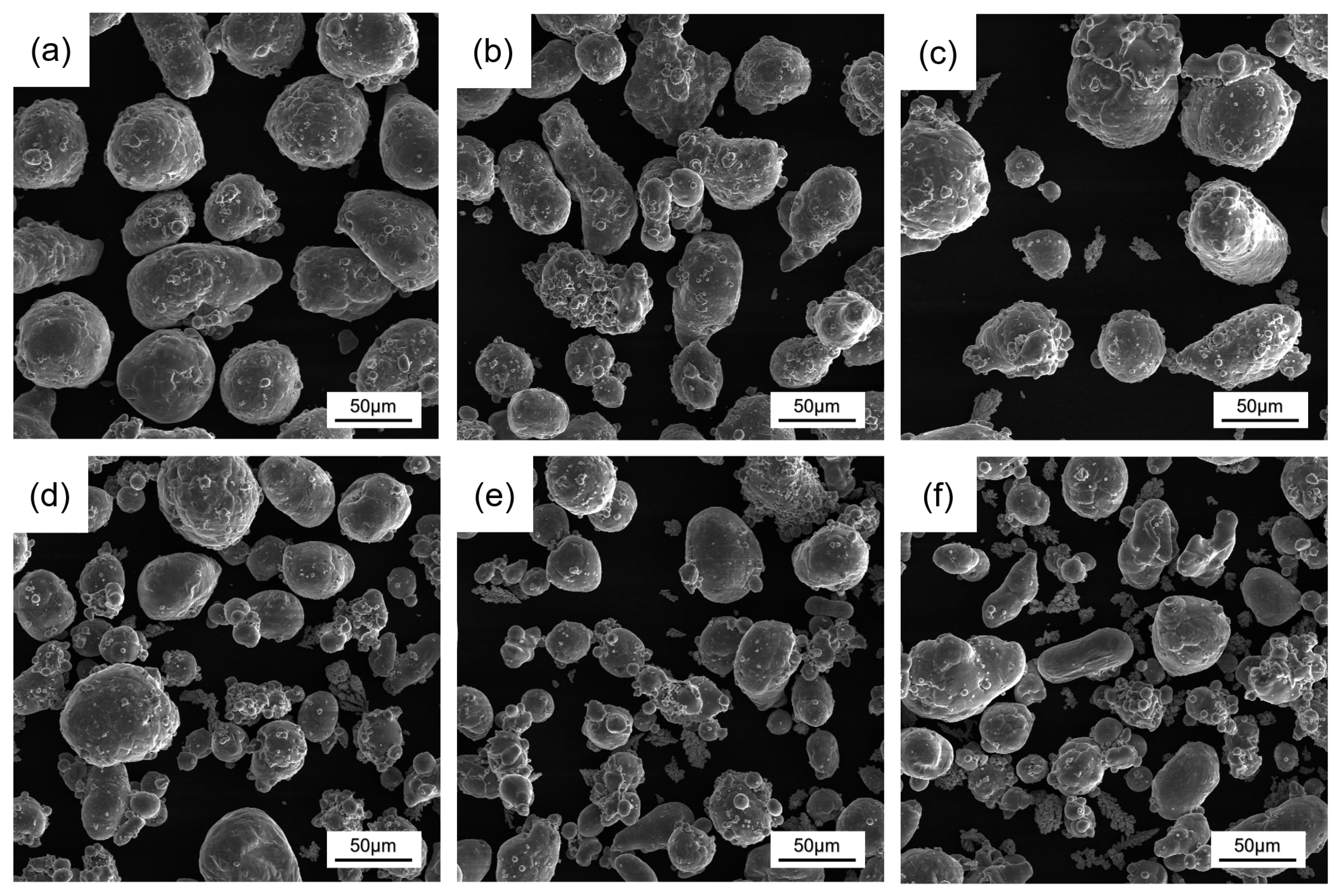
3.1. Powder Composition
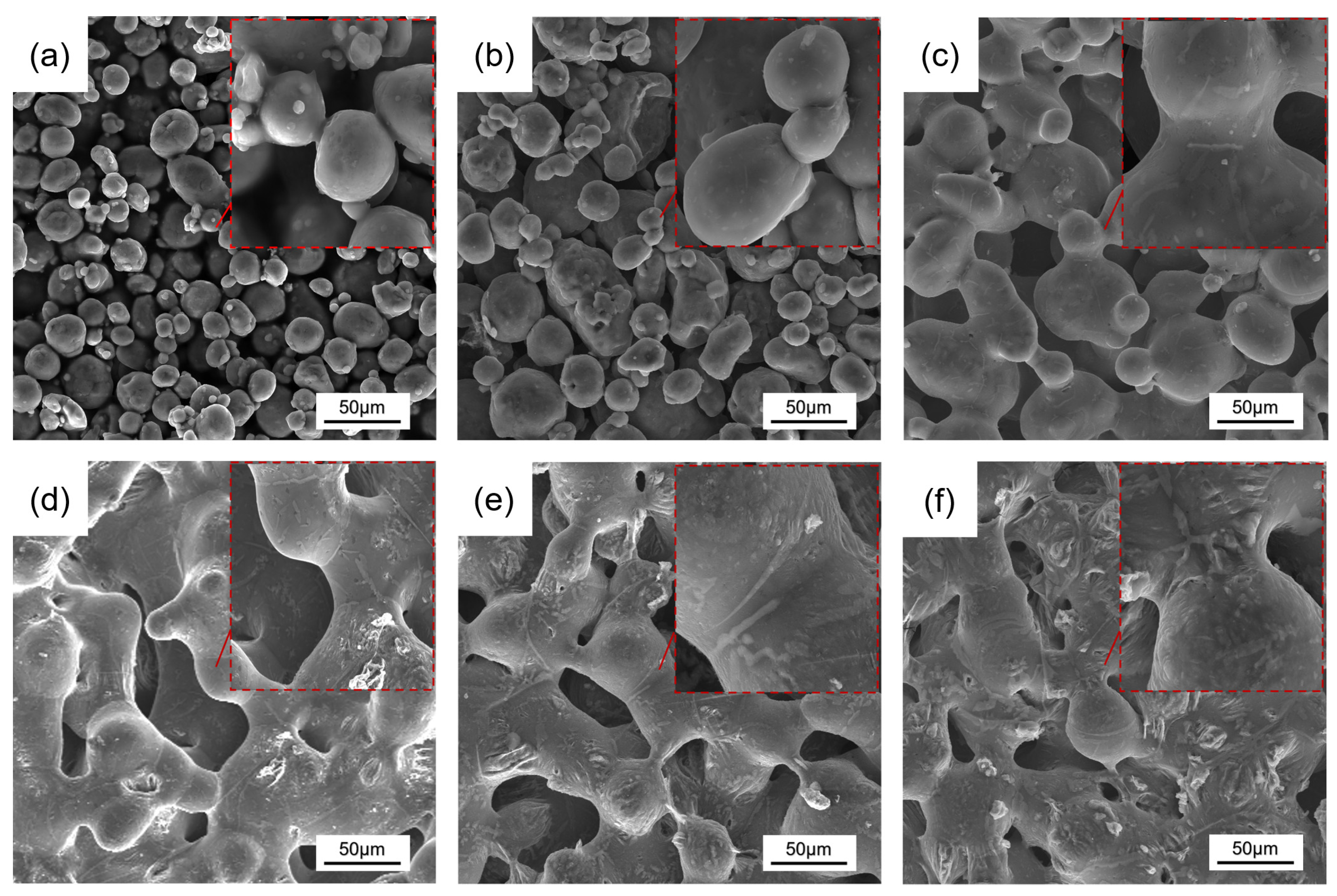
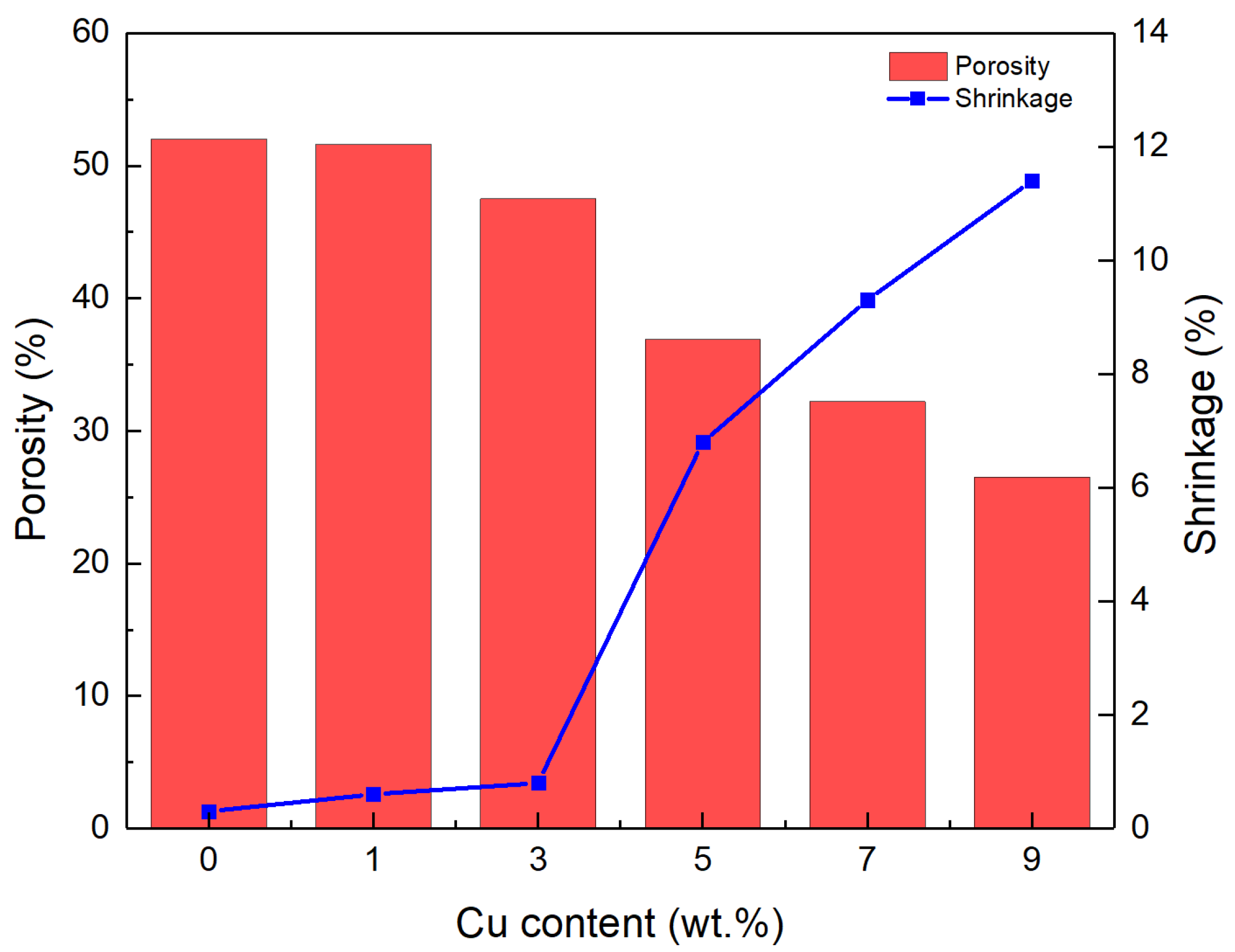
Alterations in the powder shape affect the pore shape of the porous structure, and the homogeneous mixing of the powder without changing the powder morphology is a prerequisite for the preparation of porous Al wicks. Figure 4 shows the morphology of the powders mixed with different Cu contents. As can be seen, the dendritic Cu particles were uniformly distributed in the Al particles, and more Cu particles were found with the increase in Cu content. At this rotation speed, the powder was subjected to a weaker collision force and its morphology did not change.
The XRD patterns of the mixed powders with different Cu contents are given in Figure 5. The results showed that only the diffraction peaks of Al were present at the beginning; then, the diffraction peaks of Cu gradually appeared with the addition of Cu content, and the peaks of Cu were higher with the increase in the content; in addition, all the powders did not have any other diffraction peaks. It can be observed that the mixed powder consisting of Cu, Al, and zirconia balls did not react after 2 h of mechanical mixing at 120 rpm at room temperature and still maintained its original composition.

3.2. Pore Structure

The microstructures of porous Al wicks prepared with different Cu contents are shown in Figure 6. It can be seen that there were numerous pores with different sizes distributed throughout the specimens. A three-dimensional, interconnected pore structure was formed, with adjacent particles interconnected to form a base skeleton. The pore size was influenced by the particle size. Most of the larger pores were formed between the larger particles, while the smaller pores were formed with the involvement of the smaller particles. Figure 6a shows that without the addition of Cu there was almost no bonding between the Al powders, indicating that the oxide film on the powder surface strongly inhibited the sintering of the Al powder. With the addition of Cu, the formation of sintering necks between powders was clearly observed, which increased with increasing Cu content, suggesting that the sintered sample has sufficient strength for application. Furthermore, the interconnected skeleton and three-dimensional interconnected pores between particles gradually improved (Figure 6b,c). When the Cu content exceeded 5 wt.% (Figure 6d–f), the sintering neck obviously grew larger, and the small particles gradually integrated into the large particles to form coarser cell walls. As the Cu content increased, the porosity significantly decreased, and the connectivity of the pores also deteriorated. The addition of a large amount of Cu makes the mixture prone to forming an intermediate phase with a low melting point through the reaction with Al2O3 or Al, which are in the liquid phase during sintering. With fewer liquid phases, the particles become wet, and their interstices are penetrated, promoting the formation of sintered necks. With more liquid phases, the Al particles are wrapped and the powder undergoes rearrangement and accelerated densification behaviors under the action of surface tension, leading to a remarkable increase in the density of the sintered samples [36,37]. Alternatively, the equilibrium concentration that is dissolved in the intermediate phase can vary due to the different particle sizes, with smaller particles dissolving more and precipitating on the surface of the larger particles, corresponding to the variation in the particle sizes in Figure 6. These changes corroborate the promotional behavior of Cu on the sintering of the porous Al wick.
As shown in Figure 7, with the increase in Cu content, the porosity decreased, while the shrinkage increased. When the Cu content increased from 0 wt.% to 3 wt.%, the porosity and shrinkage changed little. During the sintering process, Cu powder and Al powder underwent a combination reaction of CuO + Al2O3→CuAlO2, as mentioned by Wang [36], and the alumina film was destroyed to promote atomic diffusion and bonding strength between the powders; at the same time, a large amount of Cu powder is consumed at this stage and only a small amount of Cu diffuses into the Al powder, resulting in the formation of less intermediate phases, which have a limited promotional effect on the formation of sintered necks. When the Cu content increased from 3 wt.% to 9 wt.%, the porosity decreased from 47.5% to 26.5%, and the shrinkage increased from 0.8% to 11.4%. This may be attributed to the sufficient diffusion of Cu atoms into the Al particles, forming more intermediate phases that are better able to wet and encapsulate the Al particles and direct particle rearrangement, which greatly contributes to the increase in the shrinkage and density of the sample. This result is also confirmed by the microstructure in Figure 6.

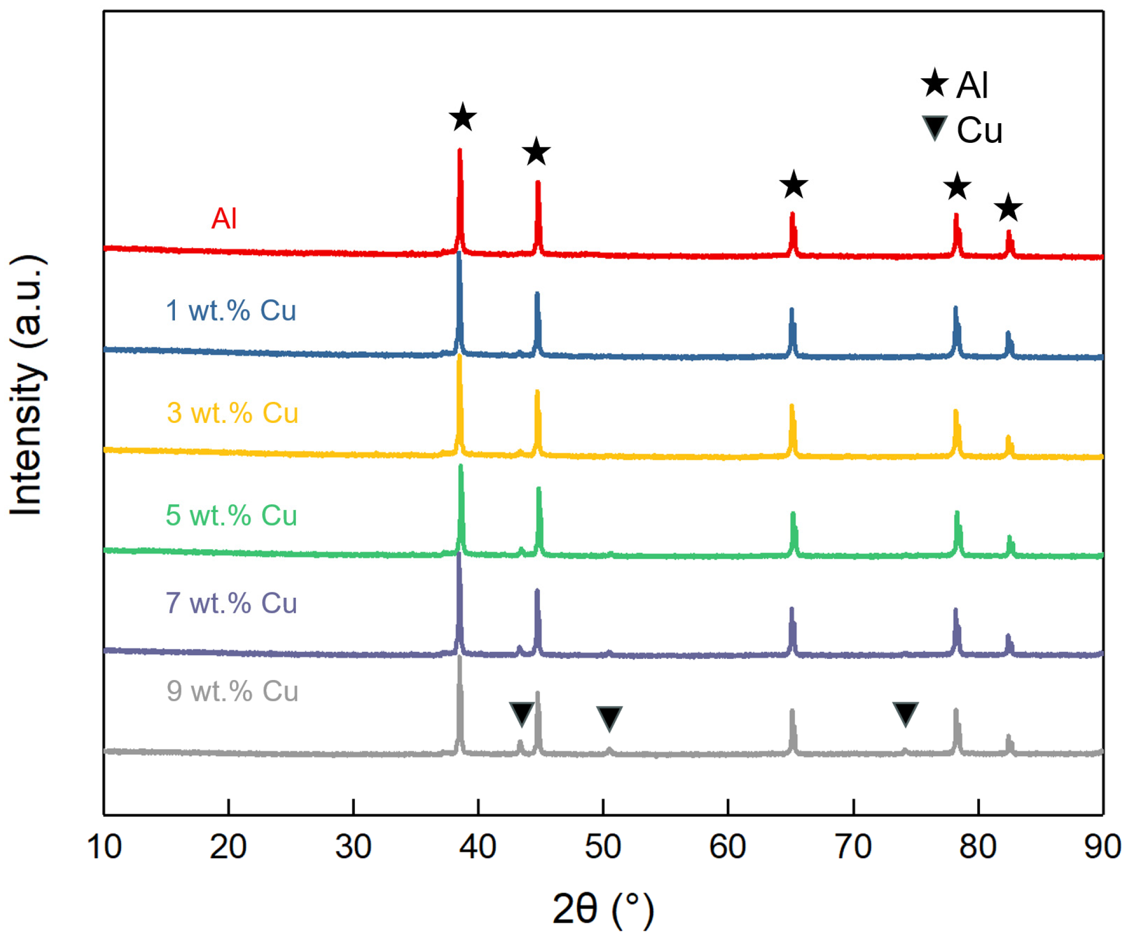
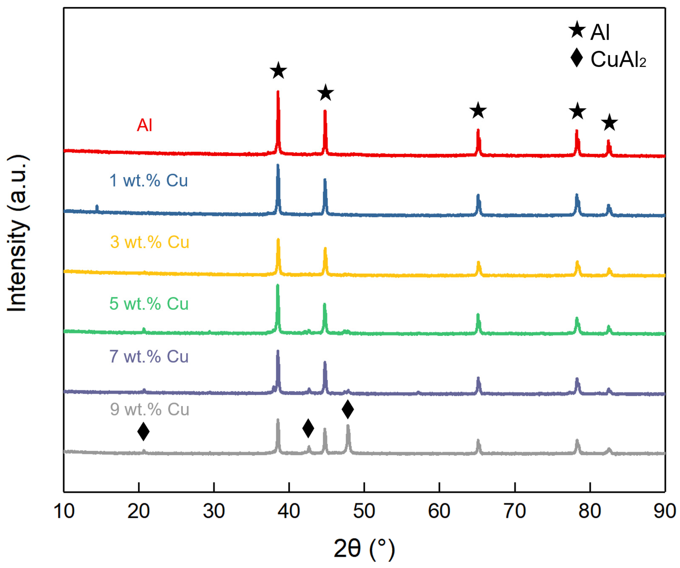
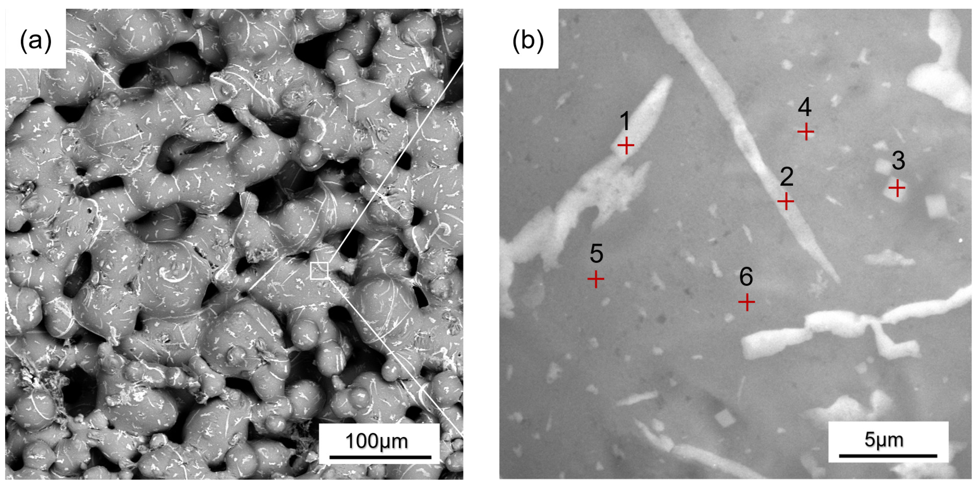
3.3. Phase Composition

Figure 8 exhibits backscattered electron (BSE) images of porous Al wicks prepared with various Cu contents. It can be observed that some precipitated phases with dot-like or dendritic forms were homogeneously distributed in the matrix phase. With a low Cu content, the precipitated phases were primarily point-like. As the Cu content increased, the number of dendritic precipitated phases increased, and their size became progressively larger. This implies that the addition of more Cu will contribute to the generation and growth of the second phase.
Figure 9 presents the XRD patterns of the samples with different Cu contents. The results showed that the matrix phase was Al and the peak of Cu was always absent, whereas the peak of CuAl2 appeared slowly and was enhanced with the addition of Cu. The XRD patterns of the samples with a Cu content of 1–3 wt.% only showed Al peaks and no CuAl2 peaks, but a small amount of the other phases can be seen in the BSE images (Figure 8). This can be ascribed to the Cu content being so low that, upon entering the Al particles, part of it forms a solid solution and part of it forms a CuAl2 phase. Both of the substances are so small that no visible peak changes can be observed at this point in the test conditions. At 5 wt.% of Cu content, the diffraction peak of CuAl2 appeared and increased in intensity while the diffraction peak of Al phase decreased in intensity, meaning that large quantities of Cu and Al were combined to form the CuAl2 phase at this time. All of the added Cu went into the Al particle form and was not present alone. Furthermore, the melting point of CuAl2 is approximately 550 °C. At the sintering temperature used in the experiment, it exists in Al-Cu liquid phase form and will greatly accelerate the densification of Al powder [38].
Figure 10 displays a backscattered electron (BSE) image of porous Al with a Cu content of 5 wt.%. Based on the energy-dispersive spectroscopy (EDS) results (Table 1), the Cu content of the dendritic precipitation phase reached 15–20 at.%, the Cu content of the dotted precipitation phase was 5–10 at.%, and the Cu content of the basal phase was in the range of 0–2 at.%. The elemental ratios of the precipitated phases did not correspond to the atomic ratios of the CuAl2 phase, and the chemical composition of the metallographic fractions at the first point was roughly equal to the atomic percentage of the (αAl + CuAl2) eutectic, suggesting that they may be (αAl + CuAl2) eutectic organizations. When sintering a porous Al wick with 5 wt.% Cu, Al2O3 reacts with CuO and takes the lead in destroying the external alumina film centered on the contact points of Cu and Al powders. Then, Cu particles contact the Al atoms inside Al particles, and Cu atoms enter the Al crystal structure through solid-phase diffusion, occupying vacancies to form the CuAl2 alloy, which is in the liquid phase at 600 °C. The liquid phase wets and wraps the Al particles and diffuses to the entire surface of the pore structure; solid-phase diffusion transforms into liquid-phase diffusion; the atom movement speed accelerates, promoting the formation of a sintering neck; simultaneously, more Al atoms enter the Al-Cu liquid phase, increasing the liquid phase, and, in the subsequent cooling process, turn to precipitate (αAl + CuAl2) eutectic and Al solid solution. Combined with the sample morphology and porous organization, it can be understood that, with the increase in Cu content, there are more powder reaction points and more Cu diffusion channels, and more CuAl2 liquid phases are formed during sintering, which are able to cover the Al powder more quickly. The phenomenon of particle rearrangement occurs, which is conducive to the formation of the sintering neck, and the formation of eutectic organization is increased.

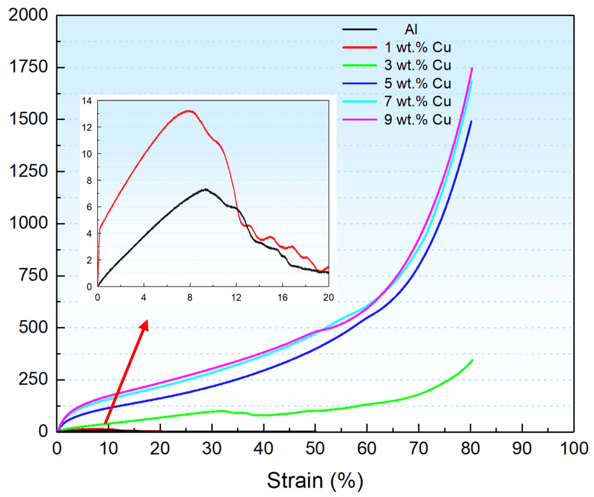
3.4. Mechanical Properties

Figure 11 presents the compressive stress–strain curves for samples with varying Cu contents. Porous Al wicks with Cu contents ranging from 0 wt.% to 1 wt.% showed no plateau stress in the stress–strain curves. Because of the low degree of particle bonding, the stress initially increases with the strain; however, when the deformation reaches a certain value, the stress decreases, and the sample breaks. In contrast, the stress–strain curve of the porous Al wicks with 3 wt.%~9 wt.% Cu showed an increasing trend with no fracture under pressure, behaving as a typical porous material [39]. As the Cu content of the sample increased, the stress at the same deformation also increased. This indicates that the addition of Cu improves the mechanical properties of the porous Al and changes its fracture behavior.
It is well-known that the mechanical properties of porous materials depend on their microstructures, including their pore size and shape, porosity, pore wall densification, and phase composition. According to Duarte [39], the mechanical properties of porous materials are measured by the plateau stress and densification strain. The peak stresses of the samples with 0 wt.% and 1 wt.% Cu content were 7.28 MPa and 13 MPa. When the Cu content increased from 3 wt.% to 9 wt.%, the plateau strength increased from 11.82 MPa to 97.59 MPa and the densification strain increased from 54% to 75%, with enhanced mechanical properties compared to the porous Al prepared by Suzuki [40], with a plateau stress of 10 MPa and a densification strain of 40%. Based on the previous results, with the increase in Cu content, the pore wall densification and the density of the specimen were both increased, the pore shape became more regular, and the pore size became more uniform. Additionally, the gradual precipitation of the CuAl2 phase in the matrix phase may also contribute to the second phase-strengthening role, and the solid solution of Cu also enhanced the strength of the porous Al wick. These factors collectively lead to the improved mechanical properties of the sintered porous Al wick.

3.5. Capillary Properties

Figure 12a shows the time–height curves for the pumping experiments of porous Al wicks with different Cu contents. All samples exhibited a good capillary performance, with the fluid height initially rapidly increasing upon contact with the fluid. The fluid’s rising height then reached a certain value, and the rising speed was gradually reduced due to the influence of gravity. All samples reached a fluid height of 110 mm before 120 s, with the samples containing 1 wt.%, 3 wt.%, and 5 wt.% Cu reaching 110 mm before 80 s, 10 mm higher compared to the fiber capillary wicks prepared by Wang [10]. Figure 12b shows the relationship between the capillary characteristic parameter and Cu content, which revealed an overall decreasing trend. The maximum capillary characteristic parameter was 7.62 × 10⁻⁸ N at 1 wt.% Cu content, while the minimum was 2.47 × 10⁻⁸ N at 9 wt.% Cu content. This variation in capillary characteristic parameter can be attributed to changes in capillary pressure and permeability.
As can be seen in Figure 12c, the permeability showed a decreasing trend due to the reduction in porosity and the fluid flow channels resulting from the activation sintering of Cu. The capillary force initially increased and then decreased with increasing Cu content. At a low Cu content, the inter-particle channels were not formed, which was unfavorable for the fluid transportation. As the 3D-connected pore structure formed and some pore shrinkage occurred, the capillary force increased, reaching a maximum value of 2309.84 Pa for the porous wick with a Cu content of 5 wt.%. Subsequently, with further increase in Cu content, the pore size between the particles decreased and even tended to close, caused by the excessive liquid phase, which resulted in a decrease in capillary force. Following the formation of the pore structure, the increase in Cu content will enhance the mechanical properties while deteriorating the pore structure, and the amount of Cu that is added should be tailored to the performance requirements when sintering the porous samples.

4. Conclusions

Porous Al wicks were prepared using loose powder sintering with Cu as a sintering aid. The effects of Cu content on the microstructure, mechanical properties, and capillary properties of the wicks were investigated. The following conclusions can be drawn:
  • With increasing Cu content, the formation of sintered necks was favored, and the pore morphology became smooth and regular, while the shrinkage increased.
  • During the sintering process, Cu and Al tend to form CuAl2, which breaks the oxide film on the surface and accelerates the densification of Al powder.
  • The compressive strength is gradually enhanced with increasing Cu content, while the capillary characteristic parameter and permeability of porous wicks are reduced.
  • At the optimal Cu amount of 3 wt.%, a porous Al wick with a porosity of 47.5%, a plateau stress of 11.82 MPa, and a capillary characteristic parameter of 6.72 × 10⁻⁸ N was obtained, meeting the requirements for wick applications.

Author Contributions

Conceptualization, B.D.; data curation, Y.C.; project administration, B.D.; resources, B.D.; visualization, Y.C. and B.D.; writing—original draft, Y.C. and B.D.; writing—review and editing, Y.C. and B.D. All authors have read and agreed to the published version of the manuscript.

Funding

The research was finished under the financial support of the National Natural Science Foundation of China (No. 51874368).

Data Availability Statement

The original contributions presented in the study are included in the article, further inquiries can be directed to the corresponding author.

Acknowledgments

The author wishes to thank the guidance of the supervisor B.D. and the Rare Metals Laboratory of the School of Materials Science and Engineering, Central South University.

Conflicts of Interest

The authors declare no conflicts of interest.

References

  1. Xie, D.; Sun, Y.; Wang, G.; Chen, S.; Ding, G. Significant Factors Affecting Heat Transfer Performance of Vapor Chamber and Strategies to Promote It: A Critical Review. Int. J. Heat Mass Transf. 2021, 175, 121132. [Google Scholar] [CrossRef]
  2. Yan, C.; Li, H.; Tang, Y.; Ding, X.; Yuan, X.; Liang, Y.; Zhang, S. A Novel Ultra-Thin Vapor Chamber with Composite Wick for Portable Electronics Cooling. Appl. Therm. Eng. 2023, 226, 120340. [Google Scholar] [CrossRef]
  3. He, G.; Sheng, Y.; Ye, G.; He, B.; Yu, B.; Tian, M.; Jian, Q.; Yu, X. Heat Transfer Performance Analysis of an Ultra-Thin Aluminum Vapor Chamber with Serrated Microgrooves. Appl. Therm. Eng. 2023, 229, 120604. [Google Scholar] [CrossRef]
  4. Ušakovs, I.; Mishkinis, D.; Galkin, I.A.; Bubovich, A.; Podgornovs, A. Experimental Thermal Characterization of the in-Wheel Electric Motor with Loop Heat Pipe Thermal Management System. Case Stud. Therm. Eng. 2023, 47, 103069. [Google Scholar] [CrossRef]
  5. Cheng, X.; Yang, G.; Wu, J. Recent Advances in the Optimization of Evaporator Wicks of Vapor Chambers: From Mechanism to Fabrication Technologies. Appl. Therm. Eng. 2021, 188, 116611. [Google Scholar] [CrossRef]
  6. Zhou, F.; Zhou, J.; Huai, X. Advancements and Challenges in Ultra-Thin Vapor Chambers for High-Efficiency Electronic Thermal Management: A Comprehensive Review. Int. J. Heat Mass Transf. 2023, 214, 124453. [Google Scholar] [CrossRef]
  7. Deng, D.; Liang, D.; Tang, Y.; Peng, J.; Han, X.; Pan, M. Evaluation of Capillary Performance of Sintered Porous Wicks for Loop Heat Pipe. Exp. Therm. Fluid Sci. 2013, 50, 1–9. [Google Scholar] [CrossRef]
  8. Zhang, Y.; Han, Z.; Yu, Y.; Rhamdhani, M.A.; Gao, Y.; Guo, C. Research on the Effective Thermal Conductivity of Nickel-Based Bi-Porous Capillary Wicks: Modeling and Validation. Int. J. Heat Mass Transf. 2024, 218, 124776. [Google Scholar] [CrossRef]
  9. Li, Q.; Lan, Z.; Chun, J.; Lian, S.; Wen, R.; Ma, X. Fabrication and Capillary Characterization of Multi-Scale Micro-Grooved Wicks with Sintered Copper Powder. Int. Commun. Heat Mass Transf. 2021, 121, 105123. [Google Scholar] [CrossRef]
  10. Wang, J.; Tang, Y.; Huang, H.; Xi, X.; Li, H.; Yan, C.; Zhang, S. Rice-Inspired Oriented Copper Fiber Wick with Excellent Capillary Performance for Ultra-Thin Vapor Chamber. Appl. Therm. Eng. 2024, 236, 121573. [Google Scholar] [CrossRef]
  11. Wan, Z.; Deng, J.; Li, B.; Xu, Y.; Wang, X.; Tang, Y. Thermal Performance of a Miniature Loop Heat Pipe Using Water–Copper Nanofluid. Appl. Therm. Eng. 2015, 78, 712–719. [Google Scholar] [CrossRef]
  12. Zhang, J.; Lian, L.; Liu, Y. Liquid Phase Enhanced Sintering of Porous Aluminum for Cylindrical Al-Acetone Heat Pipe. Int. J. Heat Mass Transf. 2020, 152, 119512. [Google Scholar] [CrossRef]
  13. Tian, W.; He, S.; Liu, Z.; Liu, W. Experimental Investigation of a Miniature Loop Heat Pipe with Eccentric Evaporator for Cooling Electronics. Appl. Therm. Eng. 2019, 159, 113982. [Google Scholar] [CrossRef]
  14. Zhang, Y.; Liu, J.; Wang, J.; Luan, T.; Chen, H.; Xue, H. Experimental Study on the Characteristics of Loop Heat Pipe with Modified Carbon Fiber Felt Wick. Appl. Therm. Eng. 2023, 234, 121239. [Google Scholar] [CrossRef]
  15. Selivanov, V.V.; Silnikov, M.V.; Markov, V.A.; Popov, Y.V.; Pusev, V.I. Using Highly Porous Aluminum Alloys and Honeycomb Structures in Spacecraft Landing Gear. Acta Astronaut. 2021, 180, 105–109. [Google Scholar] [CrossRef]
  16. Aperador, W.; Delgado, A.; Bautista, J. Improved Corrosion Protection Properties in Anodic Films Type Porous on 2024 T3 Aluminium Alloys Obtained by Pulse Reverse Plating. Int. J. Electrochem. Sci. 2013, 8, 9607–9617. [Google Scholar] [CrossRef]
  17. Bang, S.; Ryu, S.; Ki, S.; Song, K.; Kim, J.; Kim, J.; Nam, Y. Superhydrophilic Catenoidal Aluminum Micropost Evaporator Wicks. Int. J. Heat Mass Transf. 2020, 158, 120011. [Google Scholar] [CrossRef]
  18. Jiang, G.; Tian, Z.; Luo, X.; Chen, C.; Hu, X.; Wang, L.; Peng, R.; Zhang, H.; Zhong, M. Ultrathin Aluminum Wick with Dual-Scale Microgrooves for Enhanced Capillary Performance. Int. J. Heat Mass Transf. 2022, 190, 122762. [Google Scholar] [CrossRef]
  19. Zhong, G.; Tang, Y.; Ding, X.; Chen, G.; Li, Z. Experimental Investigation on Wettability and Capillary Performance of Ultrasonic Modified Grooved Aluminum Wicks. Int. J. Heat Mass Transf. 2021, 179, 121642. [Google Scholar] [CrossRef]
  20. Wu, L.; Yu, Z.; Liu, C.; Ma, Y.; Huang, Y.; Wang, T.; Yang, L.; Yan, H.; Liu, W. Microstructure and Tensile Properties of Aluminum Powder Metallurgy Alloy Prepared by a Novel Low-Pressure Sintering. J. Mater. Res. Technol. 2021, 14, 1419–1429. [Google Scholar] [CrossRef]
  21. Chai, G.; Lu, H.; Nie, Z.; Jia, E.; Wang, J.; Guo, F. Strengthening Mechanism of Porous Aluminum Foam by Micro-Arc Discharge. Tribol. Int. 2024, 191, 109169. [Google Scholar] [CrossRef]
  22. Paramore, J.D.; Dunstan, M.K.; Butler, B.G.; Lewis, D.O. Powder Casting: Producing Bulk Metal Components from Powder without Compaction. JOM 2020, 72, 3112–3120. [Google Scholar] [CrossRef]
  23. Torres, Y.; Lascano, S.; Bris, J.; Pavón, J.; Rodriguez, J.A. Development of Porous Titanium for Biomedical Applications: A Comparison Between Loose Sintering and Space-Holder Techniques. Mater. Sci. Eng. C 2014, 37, 148–155. [Google Scholar] [CrossRef] [PubMed]
  24. Duan, B.H.; Shen, T.; Wang, D.Z. Effects of Solid Loading on Pore Structure and Properties of Porous Feal Intermetallics by Gel Casting. Powder Technol. 2019, 344, 169–176. [Google Scholar] [CrossRef]
  25. Jiang, B.; Zhao, N.Q.; Shi, C.S.; Li, J.J. Processing of Open Cell Aluminum Foams with Tailored Porous Morphology. Scr. Mater. 2005, 53, 781–785. [Google Scholar] [CrossRef]
  26. Jiang, B.; Zhao, N.Q.; Shi, C.S.; Du, X.W.; Li, J.J.; Man, H.C. A Novel Method for Making Open Cell Aluminum Foams by Powder Sintering Process. Mater. Lett. 2005, 59, 3333–3336. [Google Scholar] [CrossRef]
  27. Yang, S.; Luo, H.; Wang, L.; Guang, Z.; Zhang, P.; Liu, Y. Interface Structure and Bonding Strength of Metallurgical Bonded Aluminum Foam Sandwich (Afs) Fabricated by Hot-Pressing. Vacuum 2023, 211, 111987. [Google Scholar] [CrossRef]
  28. Jafari, M.J.; Madvari, R.F.; Ebadzadeh, T. Optimized Design and Experimental Validation of Sound Absorption Coefficient Performance in Aluminium Metal Foam by Spark Plasma Sintering. Heliyon 2023, 9, e16428. [Google Scholar] [CrossRef] [PubMed]
  29. MacAskill, I.A.; Hexemer, R.L.; Donaldson, I.W.; Bishop, D.P. Effects of Magnesium, Tin and Nitrogen on the Sintering Response of Aluminum Powder. J. Mater. Process. Technol. 2010, 210, 2252–2260. [Google Scholar] [CrossRef]
  30. Liu, R.; Xiang, D. Low-Temperature Synthesis of Mullite by Molten Molybdenum Trioxide Assisted Mesoporous Aluminum Source Dissolution. Ceram. Int. 2023, 49, 27688–27696. [Google Scholar] [CrossRef]
  31. Sonoda, T.; Katou, K.; Asahina, T.; Banno, T.; Yamada, Y. Improvement of Porous Structure of Sintered Highly Porous Aluminum Materials by Surface Modification of Aluminum Particles with Tin. Surf. Interface Anal. 2008, 40, 1736–1740. [Google Scholar] [CrossRef]
  32. Gulevskiy, V.A.; Antipov, V.I.; Vinogradov, L.V.; Tsurikhin, S.N.; Kolmakov, A.G.; Gulevskiy, V.V.; Prutskov, M.E. Study of a Highly Porous Composite Material Based on an Aluminum Matrix with an Ordered Cellular Structure Formed by Hollow Copper–Graphite Spherical Granules. Inorg. Mater. Appl. Res. 2022, 13, 480–484. [Google Scholar] [CrossRef]
  33. Tang, Y.; Deng, D.; Lu, L.; Pan, M.; Wang, Q. Experimental Investigation on Capillary Force of Composite Wick Structure by IR Thermal Imaging Camera. Exp. Therm. Fluid Sci. 2010, 34, 190–196. [Google Scholar] [CrossRef]
  34. Tang, Y.; Tang, H.; Li, J.; Zhang, S.; Zhuang, B.; Sun, Y. Experimental Investigation of Capillary Force in a Novel Sintered Copper Mesh Wick for Ultra-Thin Heat Pipes. Appl. Therm. Eng. 2017, 115, 1020–1030. [Google Scholar] [CrossRef]
  35. Lago, M.; Araujo, M. Capillary Rise in Porous Media. Phys. A Stat. Mech. Appl. 2001, 289, 1–17. [Google Scholar] [CrossRef]
  36. Wang, Z.; Liang, K.; Chan, S.; Tang, Y. Fabrication of Nano CuAl2O4 Spinel for Copper Stabilization and Antibacterial Application. J. Hazard. Mater. 2019, 371, 550–557. [Google Scholar] [CrossRef]
  37. Jacob, K.T.; Alcock, C.B. Thermodynamics of CuAlO2 and CuAl2O4 and Phase Equilibria in the System Cu2O-CuO-Al2O3. J. Am. Ceram. Soc. 1975, 58, 192–195. [Google Scholar] [CrossRef]
  38. Massalski, T.B. The Al−Cu (Aluminum-Copper) System. Bull. Alloy Phase Diagr. 1980, 1, 27–33. [Google Scholar] [CrossRef]
  39. Duarte, I.; Fiedler, T.; Krstulović-Opara, L.; Vesenjak, M. Brief Review on Experimental and Computational Techniques for Characterization of Cellular Metals. Metals 2020, 10, 726. [Google Scholar] [CrossRef]
  40. Suzuki, A.; Kosugi, N.; Takata, N.; Kobashi, M. Microstructure and Compressive Properties of Porous Hybrid Materials Consisting of Ductile Al/Ti and Brittle Al3Ti Phases Fabricated by Reaction Sintering with Space Holder. Mater. Sci. Eng. A 2020, 776, 139000. [Google Scholar] [CrossRef]
Figure 1. The appearance of the raw powder: (a) Cu powder; (b) Al powder.
Metals 14 00386 g001
Figure 2. Shape of sintered sample: (a) terete; (b) sheet.
Metals 14 00386 g002
Figure 3. Experimental setup for suction performance.
Metals 14 00386 g003
Figure 4. Morphology of powders with different Cu contents: (a) 0 wt.%; (b) 1 wt.%; (c) 3 wt.%; (d) 5 wt.%; (e) 7 wt.%; (f) 9 wt.%.
Metals 14 00386 g004
Figure 5. XRD patterns of mixed powders with different Cu contents.
Metals 14 00386 g005
Figure 6. The microstructures of porous Al wicks prepared with different Cu contents: (a) 0 wt.%; (b) 1 wt.%; (c) 3 wt.%; (d) 5 wt.%; (e) 7 wt.%; (f) 9 wt.%.
Metals 14 00386 g006
Figure 7. Porosity and shrinkage of porous Al wicks with different Cu contents.
Metals 14 00386 g007
Figure 8. Backscattered electron (BSE) images of porous Al wicks prepared at different Cu contents: (a) 0 wt.%; (b) 1 wt.%; (c) 3 wt.%; (d) 5 wt.%; (e) 7 wt.%; (f) 9 wt.%.
Metals 14 00386 g008
Figure 9. XRD patterns of porous Al wicks with different Cu contents.
Metals 14 00386 g009
Figure 10. Backscattered electron (BSE) image of porous Al wicks: (a) samples with 5 wt.% Cu content; (b) magnification of region enclosed by the white square in (a).
Metals 14 00386 g010
Figure 11. Stress–strain curves of porous Al wicks with different Cu contents.
Metals 14 00386 g011
Figure 12. Capillary performance parameters of porous Al wicks with different Cu contents: (a) time-height curves; (b) capillary characteristic parameters; (c) permeability and capillary pressure.
Metals 14 00386 g012
Table 1. Analysis of analyte point components.
PointAl/at.%Cu/at.%Total/at.%
181.518.5100
285.614.4100
393.16.9100
493.26.8100
599.10.9100
6991100
Disclaimer/Publisher’s Note: The statements, opinions and data contained in all publications are solely those of the individual author(s) and contributor(s) and not of MDPI and/or the editor(s). MDPI and/or the editor(s) disclaim responsibility for any injury to people or property resulting from any ideas, methods, instructions or products referred to in the content.

