Article

Numerical Study on the Heat Transfer of Confined Air-Jet Quenching of Steel Sheets

State Key Laboratory of Rolling and Automation, Northeastern University, Shenyang 110819, China
*
Author to whom correspondence should be addressed.
Metals 2024, 14(4), 377; https://doi.org/10.3390/met14040377
Submission received: 8 February 2024 / Revised: 19 March 2024 / Accepted: 21 March 2024 / Published: 24 March 2024
(This article belongs to the Special Issue Metal Rolling and Heat Treatment Processing)

Abstract

:
The high flatness quenching of ultra-high-strength steel sheets is a technical problem in the steel industry. In this study, the traditional water and spray quenching methods were abandoned, and the roller-constrained slot air-jet quenching method was proposed for steel sheets below 3 mm thickness, which provided a theoretical reference for producing thinner, wider, and higher-flatness steel sheets. A 2D roller-constrained slot air-jet numerical model was established to study the flow field and heat transfer characteristics under the conditions of Reynolds number 24,644–41,076, a dimensionless jet height of 16–24, and a jet angle of 45°–135°. The results showed that the average Nusselt number on the heat transfer surface was proportional to Rem. At the same time, high-intensity heat transfer was achieved when the dimensionless height and jet angle were properly combined. At the same Reynolds number, the heat transfer intensity could be increased by 289%. In addition, the position of the peak Nusselt number was affected by reducing the jet angle, which served as an effective strategy for adjusting the martensite ratio and obtaining ideal mechanical properties.

1. Introduction

Ultra-high-strength steel (UHSS) exhibits excellent comprehensive strength, toughness, formability, and weldability properties and is widely used in equipment manufacturing, transportation, and the petrochemical industry [1,2]. With the progression of modern industry towards large-scale, lightweight, and green equipment, users increasingly demand steel sheets with a thickness of less than 3 mm, a width greater than 2 m, and strength above 960 MPa.
According to the elastic buckling theory, the critical buckling stress of compressed sheets under ideal conditions is considered inversely proportional to the quadratic aspect ratio (Equation (1)) [3]. In the traditional quenching process using water or spray as the cooling medium, four heat transfer modes, namely, film boiling, transition boiling, nucleate boiling, and jet impingement, will occur during the cooling process of the steel sheets. Due to the rewetting phenomenon in the high temperature zone, film boiling and nucleate boiling heat transfer modes with a significant difference in heat transfer coefficients will exist on the steel sheet surfaces simultaneously, forming a severe thermal gradient in the length and width directions, serving as an important reason for quenching distortion [4]. In addition, the disordered surface water flow caused by jet impingement and partial oxide layer shedding caused by excessive wall cooling rate will aggravate the uneven cooling of the entire wall, making steel sheets with a thickness of less than 3 mm more susceptible to quenching distortion [5]:
σ c r = K E π 2 12 ( 1 v 2 ) ( b / t ) 2
where σ c r denotes the critical stress (MPa), K is the buckling coefficient, E is the modulus of elasticity, v is the Poison ratio, t denotes the thickness (m), and b is the width (m).
Gas jets show high cooling uniformity and high shape control ability, especially in the continuous quenching of strip steel [6,7] and galvanizing production lines [8], providing a new approach for addressing the quenching distortion of sheets. Among different gases, air jets have the advantages of safety and economy. In past decades, Perry [9] and Martin [10] have carried out pioneering research in this field, while in recent years, Barbosa et al. [11], Shukla et al. [12], and Dewan et al. [13] have systematically reviewed the research in this field. Several studies [14,15,16] have assessed the contribution of each variable to heat transfer through the design of experiments (DOE) [17], indicating that the Reynolds number, nozzle shape, and H/D were important factors affecting heat transfer, while S/D and target geometry had less influence. Other studies [18,19] showed that jet angle also served as a key factor affecting heat transfer.
In a numerical simulation study of circular jet impact plates, Jensen and Walther et al. [20] determined that a higher Reynolds number could increase the heat transfer rate by increasing the turbulence level near the stagnation point. Shariatmadar et al. [21] noted that a lower Reynolds number and larger jet height reduced jet kinetic energy, resulting in uneven jet impact on the target plate and reduced heat transfer intensity. Goodro et al. [22] observed that the qualitative distribution of local Nusselt numbers under different Reynolds numbers was similar for array impinging jets with the same proportion of hole spacing. Li et al. [23] found that increasing the Reynolds number and reducing the dimensionless area could improve the heat transfer coefficient and cooling efficiency under the same coolant consumption condition. For the slot jet impingement array [24], the average Nusselt number on the impingement plate will also increase with an increase in Reynolds number under both unconstrained and constrained configurations.
Air jets typically use two types of nozzles: orifice jets and slot jets. Wen et al. [25] conducted numerical simulations on the heat transfer performance of seven types of nozzles, including circular, semicircular, rectangular, square, isosceles triangular, flower, and cross types. The flower-shaped nozzles severely deteriorated heat transfer uniformity under various operating conditions, while the circular nozzles achieved higher cooling rates at high jet heights. By comparing the heat transfer performance of two types of jets, Sarkar & Singh et al. [26] found that circular jets had a higher stagnation point heat transfer rate, while slot jets had higher heat transfer uniformity. In addition, a lower H/D value could lead to a higher heat transfer rate in both single jet [27] and array jet [24] heat transfer systems, due to interaction between the jet momentum and local cross flow [28]. Garimella and Schroeder et al. [29] also found through experimentation that a decrease in H/D could increase the heat transfer intensity by increasing the turbulence intensity of the jet, and the higher the Reynolds number, the more noticeable the effect. Ichikawa et al. [30] observed through 3D PIV that a larger rolled-up structure and improved Nusselt number distribution were produced at a small impact distance, which was attributed to the high momentum flow in the entire wall.
When the nozzle perpendicularly impacts the plate, the local Nusselt number and surface pressure on the impact plate will be symmetrically distributed with the stagnation point as the center. With increasing nozzle inclination angle, the position of the maximum Nusselt number will move to the inclined side, and the heat transfer on the inclined side will be higher than on the other side [31]. Attalla et al. [18] experimentally assessed the heat transfer characteristics of two inclined circular jet impinging plates. The results indicated that the average heat transfer coefficient was the highest within an inclination angle range of 10°–20°, which was caused by an increase in eddy currents and a decrease in the impact area. Ingole and Sundaram [19] used a free circular inclined jet to impinge a target with a surface area of 0.0285 m2, and the results showed that the average Nusselt number decreased with increasing jet inclination. Pawar and Patel et al. [32] conducted numerical simulation research on the heat transfer characteristics of a free inclined slot jet impacting a hot moving surface and found that at different plate velocities, the wall average and local Nusselt numbers were the largest at an inclination angle of 25°.
In this paper, different from traditional water and spray quenching technology, air-jet cooling was introduced into the field of ultra-high-strength steel sheet quenching to improve heat transfer uniformity. A lack of tension control will be observed during the quenching of the steel sheet, compared to the continuous quenching process of the strip steel. At this point, the pressure roller constraint will serve as an important condition to ensure the quenched sheet shape. In addition, due to uncoiling and quenching distortion, front-end bending will occur during the quenching process, making it necessary to design reasonable cooling equipment to improve the safety of industrial production.
In this study, a basic configuration of roller-constrained slot air-jet quenching equipment was designed for steel sheets thinner than 3 mm to explore the industrial application of air-jet cooling. The near-surface flow field and wall heat transfer properties of steel sheets will be more complex due to the small roller distance and unique jet box design. How to improve cooling intensity and achieve heat treatment processes has become the key to the industrial application of air-jet quenching technology. In the research on single-phase heat exchangers [33] and micro-channel heat sinks [34], reasonable internal channel design and wall conditions greatly improved heat transfer, which is similar to the research in this paper. Numerical simulation played an important role in solving the above problems. In this study, the flow field characteristics and heat transfer characteristics under different jet Reynolds numbers, jet heights, and jet angles were also assessed through numerical simulations. This research provides a theoretical reference for the new generation of high-flatness steel sheet quenching technology and will promote the industrial production of thinner, wider, and higher-flatness steel sheets.

2. Methodology

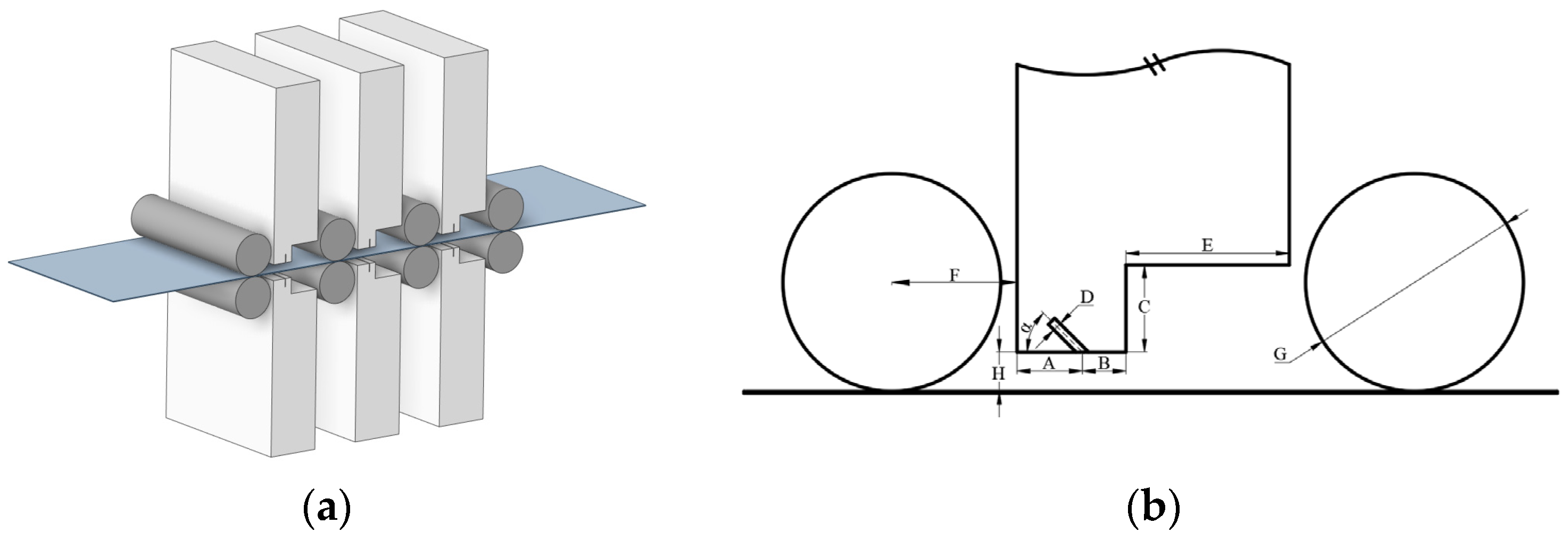
2.1. Problem Description

A 3D model of roller-constrained slot air-jet quenching equipment is shown in Figure 1a. The steel sheet entered the heat exchange zone from the left pressure roller, and the upper and lower rollers imposed constraints to reduce distortion during quenching. The nozzle was located between the two groups of constraint rollers on the same side to cool the steel sheet. A small roller diameter and small roller distance design were adopted to realize dense constraints. And the same pressure roller size and distance were used to ensure the consistency of the constraints. To simultaneously achieve high cooling intensity and high quenching safety, the air-jet box was designed as a stepped asymmetric shape. The partial dimensions are shown in Figure 1b and Table 1.

2.2. Turbulence Model and Numerical Procedure

The SST k-ω model, developed by Menter [35], combines the advantages of the k-ω model and k-ε model in the near-field and far-field, with good applicability to different jet types [36,37]. Hofmann et al. [38] used 13 widely used RANS turbulence models to predict the heat transfer and flow characteristics of circular jet impinging on plates. The results showed that the SST k-ω model with the option of activating transition flow provided more accurate results, and other studies reached similar conclusions [25,39,40]. In addition, SST k-ω presented good prediction results for jet impingement on static [41,42,43] and moving plates [44,45]. In this study, the limitation of jet flow by a stepped jet box and pressure roller produced complex flow and heat transfer near the wall; thus, the SST k-ω model was a valid choice. Its turbulent kinetic energy k and specific dissipation rate ω were obtained from the following transport equation [46]:
( ρ k ) t + ( ρ u i k ) x i = P ˜ k β * ρ k ω + x i [ ( μ + σ k μ t ) k x i ]
( ρ ω ) t + ( ρ u i ω ) x i = α ρ S 2 β ρ ω 2 + x i [ ( μ + σ ω μ t ) ω x i ] + 2 ( 1 F 1 ) ρ σ ω 2 1 ω k x i ω x i
where ui and xi are the velocity components and coordinate direction, respectively. ρ and μ denote the fluid density and dynamic viscosity. P ˜ k , S, and F1 denote the production limiter, strain rate and blending function, respectively. σk, σω, a, and β are constants that can be calculated by Equation (9).
The kinematic eddy viscosity was defined as follows [46]:
v t = a 1 k max ( a 1 ω , S F 2 )
The auxiliary relations in the above equation were defined as follows [46]:
F 1 = tanh { { min [ max ( k β * ω y , 500 v y 2 ω ) , 4 ρ σ ω 2 k C D k ω y 2 ] } 4 }
C D k ω = max 2 ρ σ ω 2 1 ω k x i ω x i , 10 10
F 2 = tanh [ [ max ( 2 k β ω y , 500 ν y 2 ω ) ] 2 ]
P ˜ k = min [ μ t u i x j ( u i x j + u j x i ) , 10 β ρ k ω ]
α = α 1 F + α 2 ( 1 F )
The specific values of constants are shown in Table 2.
The inlet Reynolds number, dimensionless velocity, dimensionless pressure, local Nusselt number, and average Nusselt number were defined by Equations (10)–(14):
R e = U 0 B ν
U = u U 0
C p = p p 0 1 2 ρ 0 U 0 2
N u x = q w B ( T w T j ) k
N u ¯ = 1 L 0 L N u x d x
where U 0 is the average jet inlet velocity, u is the jet velocity, p 0 is the ambient pressure, B denotes the hydraulic diameter, q w is the wall heat flux, T w is the wall temperature, T j is the jet inlet temperature, and L is the pressure roller spacing equal to 0.24 m.
The finite volume approach was used to discretize the governing equations, utilizing Green–Gauss node-based for spatial discretization of the gradient. The second-order upwind scheme was used for discretization of the energy space, and the second-order scheme was used for the discretization of the pressure space. The coupled method was used to solve the pressure–velocity coupling, and the solution was considered converged when the normalized residual fell below 10−6 for the energy equation and below 10−4 for all other variables. A stricter convergence limit for the energy equation was required to ensure more accurate wall heat transfer data. Pressure-Based Solver of ANSYS Fluent 2020R2 was used for numerical simulation, with Tecplot utilized for post-processing.

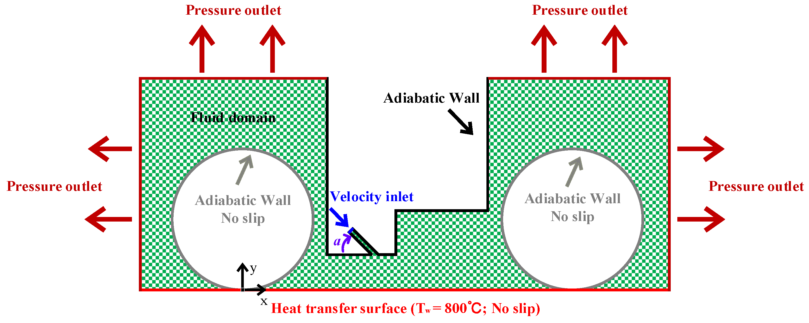
2.3. Boundary Conditions

Steel sheets produced by the modern steel industry typically have a width larger than 1 m. The length–width ratio of the slot nozzle will typically be large enough that the error caused by treating it as a two-dimensional form can be ignored. According to the local dimensions in Figure 1b, a 2D fluid calculation domain was constructed, as shown in Figure 2, where the origin of the coordinates consisted of the intersection of the left pressure roller and the steel sheet surface.
The parameters studied in this study were as follows: inlet Reynolds number Re, dimensionless height H/D, nozzle angle a. The boundary conditions are as follows:
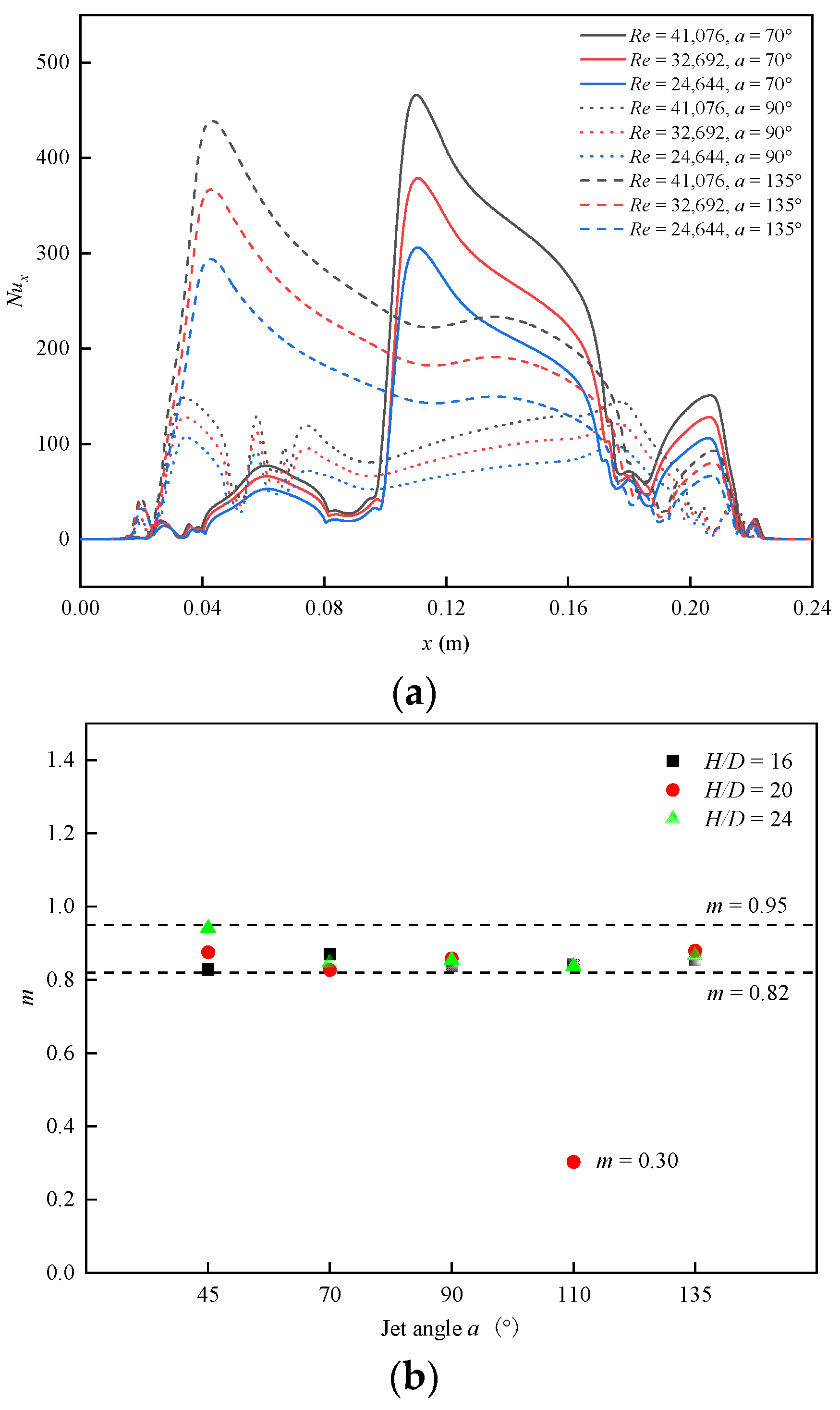
  • The inlet Reynolds numbers were 41,076, 32,692, and 24,644. The jet temperature was 26 °C, and the turbulence intensity was maintained at 4%. The thermal conductivity, specific heat capacity, and viscosity of air were polynomial functions related to temperature [32].
  • Considering the cooling intensity and safety factors, dimensionless heights H/D of 24, 20, and 16 were selected.
  • The nozzle angles a were 45°, 70°, 90°, 110°, and 135°, according to the left side wall of the nozzle.
  • The grade of UHSS used in this paper was Q1100, and its chemical composition is shown in Table 3. The surface temperature of the steel sheet was fixed at 800 °C. At this temperature, the steel was in an austenitic state. The density was 7850 kg/m3, the specific heat was 596 J·kg−1·K−1, and the thermal conductivity was 24.8 W·m−1·K−1. The pressure roller wall and steel sheet surface were assumed to be stationary, and the roughness constant was 0.5. The walls of the air-jet box and pressure roller consisted of adiabatic boundaries. The ambient temperature was the same as the jet temperature.

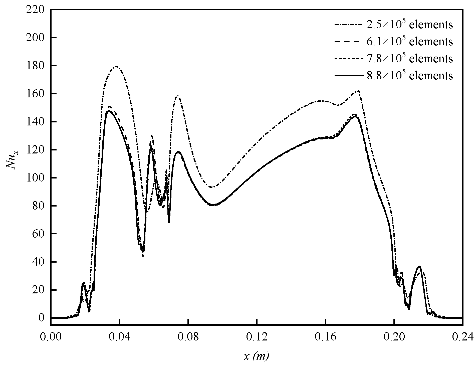
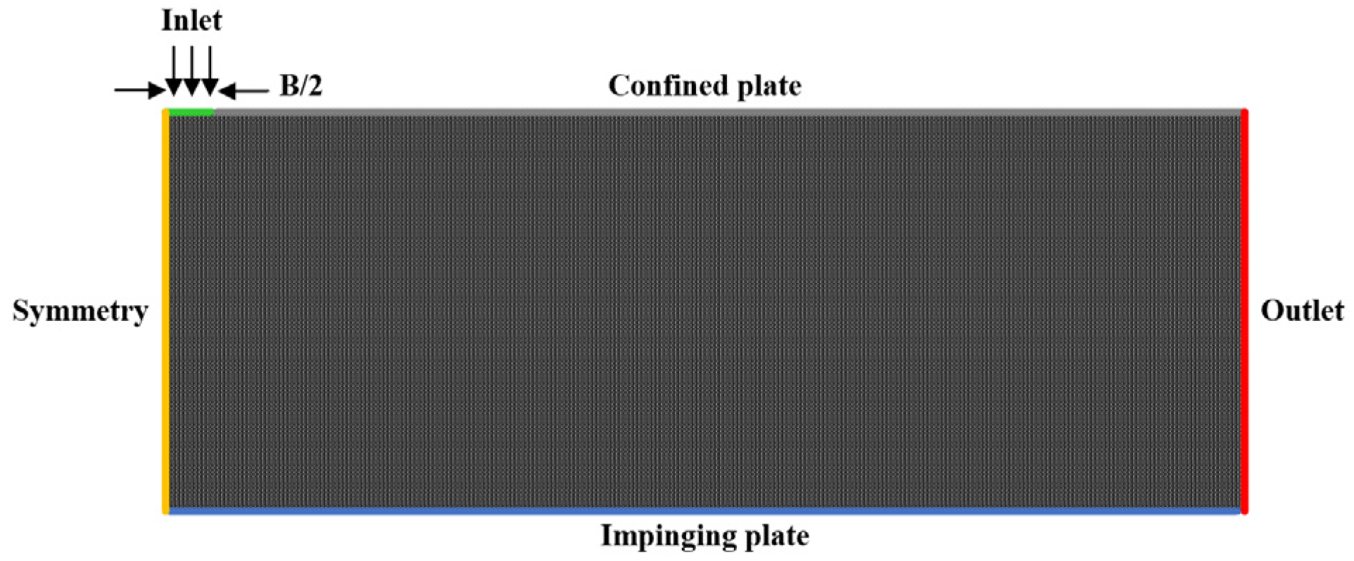
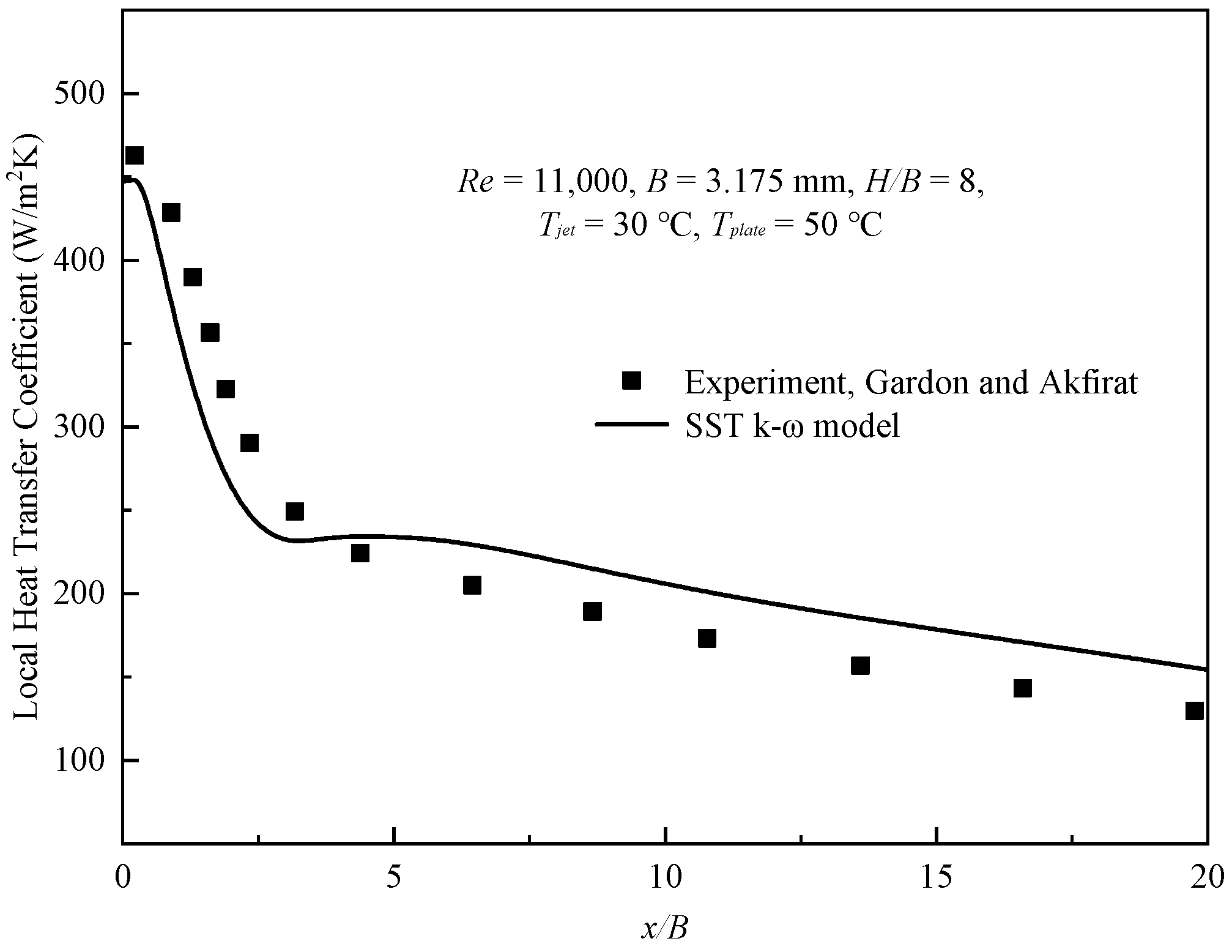
2.4. Grid Independence and Verification of the Numerical Solution Procedure

The mesh number was regulated by the mesh size using the meshing tool in the ANSYS workbench 2020 R2. To capture the larger temperature and velocity gradient near the impact wall, a dense inflation layer was set near the sheet wall to ensure that y+ < 1. In the model of Re = 41,076, H/D = 20, and a = 90°, four types of grid numbers were set to study the grid independence, which were 8.8 × 10⁵, 7.8 × 10⁵, 6.1 × 10⁵, and 2.5 × 10⁵, respectively. The average orthogonality of all grids was greater than 0.97, and the results are shown in Figure 3. When the number of grids was greater than 7.8 × 10⁵, the change in Nux was less than 1%. To ensure the fine resolution of the Nux distribution, the grid was divided into 8.8 × 10⁵ elements in the calculation.
The SST k-ω turbulence model was validated by experimental data from Gardon and Akfirat [47] at Re = 11,000, B = 3.175 mm, H/B = 8. The computational domain of the numerical model is shown in Figure 4, where the jet and wall temperatures are 30 °C and 50 °C, respectively. The convective heat transfer coefficient distribution obtained by the SST k-ω turbulence model is in good agreement with the experimental values in Figure 5.

3. Results and Discussion

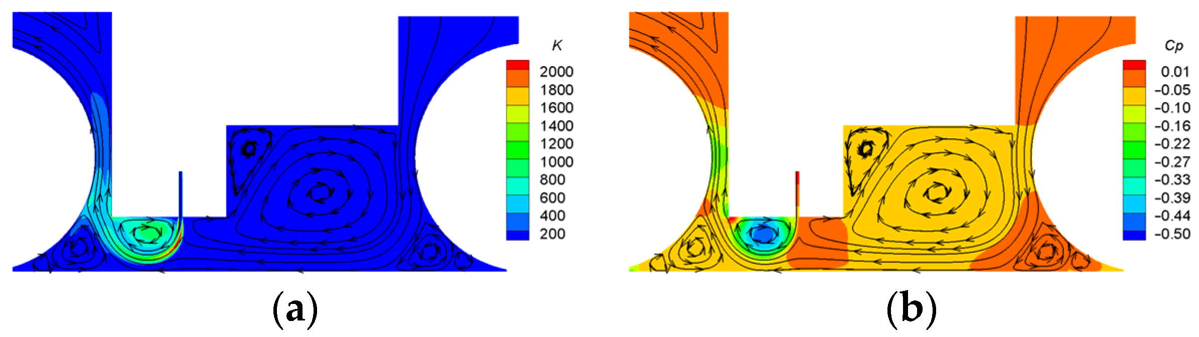
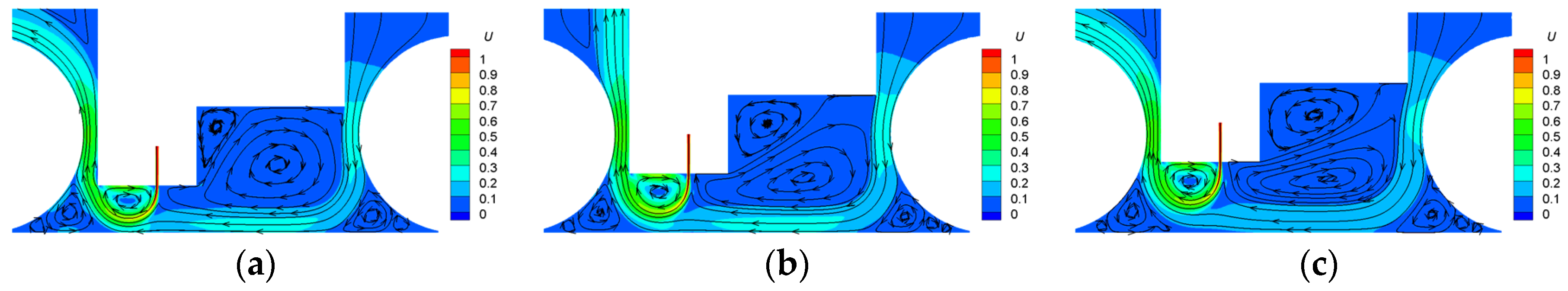
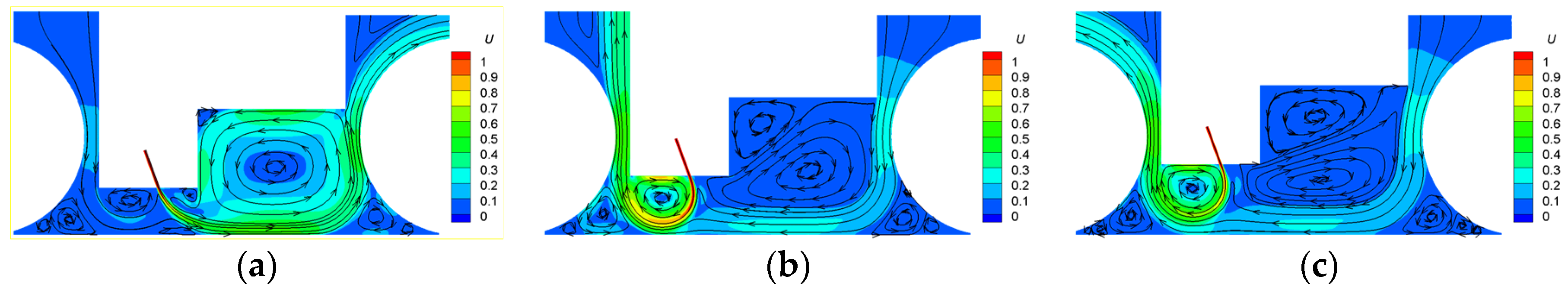
3.1. Flow Field Analysis

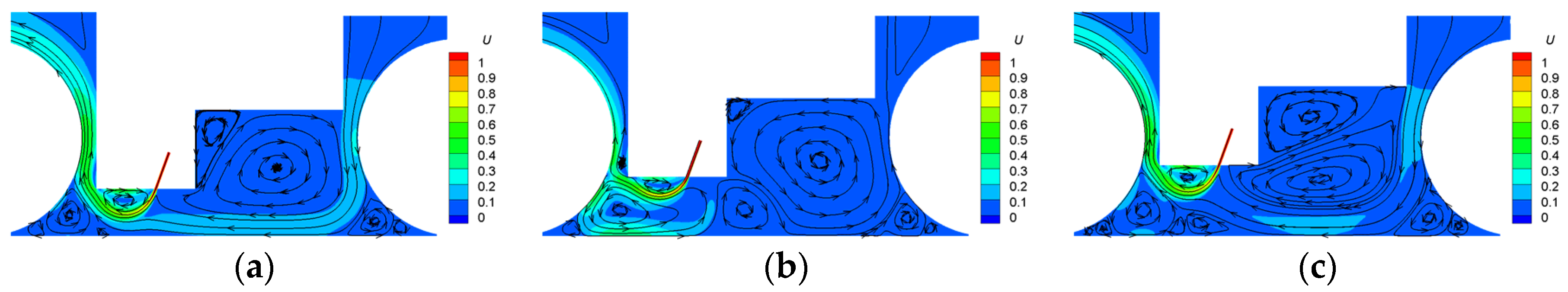
3.1.1. Perpendicular Jet

The flow field in this study differed from conventional confined jet impingement due to the limitation of a stepped confined wall and pressure roller on jet flow. This was mainly related to the jet angle and jet height. When the jet angle was 90°, the higher confined wall on the right side caused more ambient air to participate in mass and momentum exchange, resulting in higher turbulent kinetic energy, as shown in Figure 6a. This reduced the fluid velocity on the right side of the jet and produced an ambient pressure greater than on the left side, causing the jet flow to deflect to the left, as shown in Figure 6b and Figure 7. The left ambient air was entrained into the jet and expelled through the left outlet without being refilled. As a result, a local low-pressure area developed close to the confined wall and a recirculation flow formed between the wall jet and the left confined wall. The jet flow was constricted to the confined wall as the pressure differential between the two sides continued to increase. The confined wall on the left side of the nozzle was short, so that only wall jet heat transfer was produced from the edge of the jet, as the size of the recirculation flow was too small to directly touch the sheet wall. In addition, the air outside was drawn in between the confined wall and the right pressure roller to form a wall jet, because the air near the right side of the jet was carried away. An additional result of the aforementioned phenomena was recirculation flow, which developed between the right confined wall and the impingement surface. In this case, wall heat transfer was mainly provided by the main jet and the wall jet from the right outlet, as shown in Figure 7a,b. With increasing H/D, the velocity of wall jet formed by main jet and suction air gradually decreased. When H/D = 24, the edge of the jet departed from the impingement wall, leaving only the wall jet produced by supplemental air to transmit heat, as shown in Figure 7c.

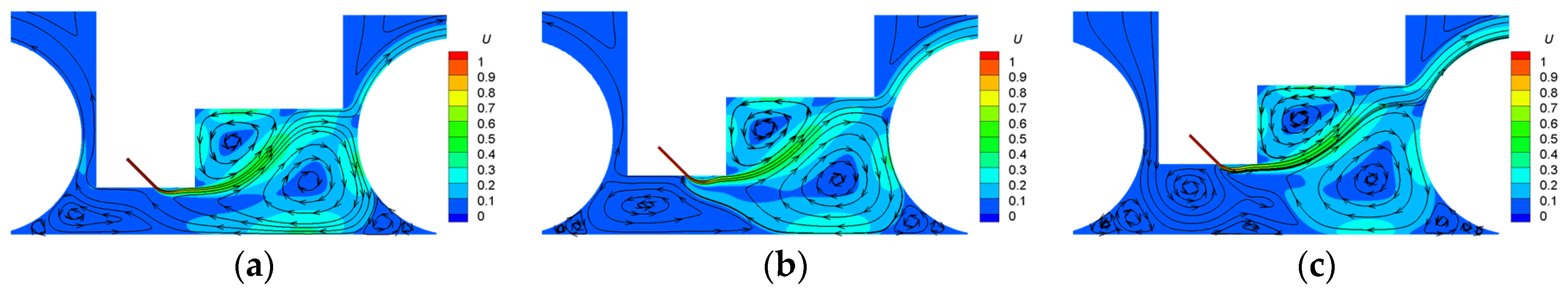
3.1.2. Nearly Perpendicular Jet

The jet height significantly affected the flow field at an inclination angle of 70°. The flow field distribution was similar to the 90° jet angle when H/D = 20 and 24, as illustrated in Figure 8. The deflection angle needed for the jet to reach the left outlet increased as the inclination angle changed, creating a larger recirculation region and wall jet region with a higher velocity and larger area, which increased the heat transfer level. When H/D = 16, more intense mass and momentum exchange still occurred on the right side of the jet. However, as the distance between the jet and the wall surface decreased, the jet contacted the wall to produce an impinging jet, and recirculation flow was created between the impinging wall and the right confined wall.
The flow field distribution at 110° and 90° was also similar, as shown in Figure 9. The recirculation region shrank as a result of the jet inclining to the left outlet, and the jet edge could not make contact with the heat transfer wall and form a wall jet. When H/D = 16 and 24, the wall heat transfer was mainly provided by the wall jet formed by the suction flow. When H/D = 20, a portion of the jet turned toward the wall to form convective impingement heat transfer because the impingement angle between the jet and the left pressure roller was nearly perpendicular. Although the flow of the jet involved in heat transfer decreased, the change in heat transfer mode still enhanced the heat transfer effect.

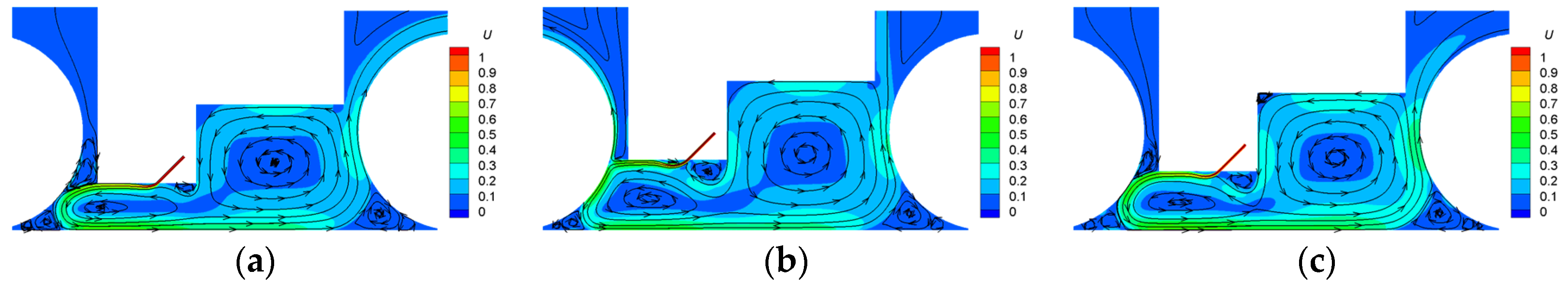
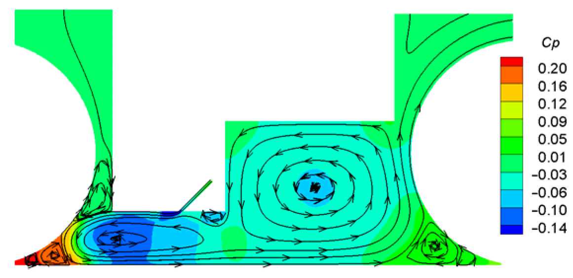
3.1.3. Small Angle Jet

The air near the confined wall was entrained and lost by the jet when the angle was small (45° or 135°), producing a localized area of low pressure. The pressure difference between the two sides pressed the jet to the confined wall, resulting in a Coanda effect. When the jet angle was 45°, the jet turned to the right confined wall after leaving the left confined wall, finally impacting the right pressure roller. The impact angle was nearly vertical, and some of the jet flowed out of the heat transfer area, while the remainder flowed to the wall to create a recirculation flow that caused heat transfer upon contacting the wall, as shown in Figure 10. Heat transfer at this angle was mainly provided by recirculation flow. The flow field at a = 135 ° is shown in Figure 11. After passing through the confined wall, the jet directly impacted the left pressure roller. When H/D = 16 and 20, the contact angle was quite small. The jet was tightly attached to the roller and moved toward the steel sheet. Because the impact angle was nearly vertical, at H/D = 24, a tiny portion of the jet escaped to the outside, which caused the flow moving toward the sheet to decrease. An adverse pressure gradient was created as the jet traveled through the semi-enclosed area bounded by the left pressure roller and the heat transfer wall. This forced the jet to turn away from the roller surface and toward the heat transfer wall, achieving heat transfer on the majority of the wall’s surface areas. An adverse pressure gradient also formed, causing the jet to move away from the heat transfer wall when it moved to the semi-closed region between the right pressure roller and the wall of heat transfer, as shown in Figure 12. Subsequently, the jet was divided into recirculation flow and output flow. The wall heat transfer at this angle was provided by the convective impact and wall jet.
In general, each parameter will have a different impact on the flow field and phenomena of wall heat transfer, due to the design of the stepped confined wall. When the jet angle was 90°, the stepped confined wall induced jet deflection, which was aggravated by pressure on both sides of the recirculation zone and prevented the jet from directly impacting the wall. In this case, wall heat transfer was mainly provided by the wall jet formed by the right suction flow and the main jet. The heat transfer of the wall jet varied with the enlargement and contraction of the left recirculation zone at angles of 70° and 110°. The constraint of the confined wall and left pressure roller modified the flow field and resulted in convective heat transfer when a = 70°, H/D = 16 and a = 110°, H/D = 20. The jet flowed closely to the confined wall when the jet angle was near the confined wall (45° and 135°), causing the Coanda effect, which prevented the jet from directly impacting the heat transfer wall. At a = 45°, wall heat transfer was provided by the recirculation flow formed by impacting the right pressure roller. When the angle was 135°, wall heat transfer was provided by the backflow guided by the left pressure roller, resulting in convective heat transfer and wall jet heat transfer.

3.2. Heat Transfer Analysis

The influence of the Reynolds number on wall heat transfer under different conditions is shown in Figure 13. The local Nusselt number Nux of the heat transfer surface at three Reynolds numbers was examined, as illustrated in Figure 13a, taking three jet angles at H/D = 16 as examples. The Nux distributions of the same configuration at different Reynolds numbers were similar, which was identical to the conclusions obtained in many studies [6,20,22,48]. The intensity of the turbulent flow increased as the Reynolds number rose, which encouraged a greater degree of mixing between the jet flow and the surrounding air, thus improving the wall Nux and Nu ¯ . Nu ¯ is typically proportional to the exponential form of Reynolds number, Rem, with the value of m remaining constant in a specific range of Reynolds numbers under a fixed configuration [49]. According to the study of single-jet and multi-jet impingement heat transfer processes, the m value ranged from 0.55 to 0.87 [11]. The value of m was mainly in the range of 0.82–0.95 when fitting the simulation results of 15 configurations in this work, and only in the case of a = 110°, H/D = 20 was 0.30, as illustrated in Figure 13b. The reason for m value decrease is depicted in Figure 9b. When the inlet Reynolds number was increased, the increased jet flow only partially contributed to heat transfer because it collided with the left pressure roller and split into two under the above configuration. The other part of the jet flowed directly out of the heat exchange zone. The increasing effect of wall heat transfer caused by an increasing Reynolds number was lessened as a result, resulting in a relatively small m value.
Although increasing the Reynolds number could considerably increase the efficiency of heat transmission, it would also increase the cost of cooling. Cooling equipment has limitations in industrial settings, making it critical to take into account variables such as manufacturing environment, production stability, and production effect. Therefore, improving the key components of equipment and adjusting the use of equipment has become the usual means in engineering, which corresponds to the regulation of nozzle height and nozzle angle in this study.
The effects of dimensionless height H/D and jet angle a on Nu ¯ in this model are shown in Figure 14. Increasing the jet height will often cause the jet and surrounding fluid to mix more thoroughly while decreasing the kinetic energy and impact strength. When the heat transfer wall temperature was higher than the jet temperature, the temperature difference between the wall and the jet would diminish as the height of the jet increased. At the same time, a low jet velocity and high jet temperature increased the boundary layer thickness in the wall jet region. Therefore, in most cases, the intensity of wall heat transfer decreased as the jet height increased (for example, a = 45°, 90°, and 135° in this work). Another key parameter impacting the wall heat transfer intensity was the jet angle, which could actively alter the flow field structure and affect the upstream and downstream heat transfer intensities. Due to the confinement of stepped confined walls and pressure rollers, the adjustment of jet height and jet angle also changed the impact angle of the jet on the pressure rollers and heat transfer wall, demonstrating different heat transfer characteristics from the parallel confined walls, especially at a = 70° and 110°.
When H/D = 24, the heat transfer wall had no effect on the jet path. A complete recirculation flow formed on the left side of the nozzle outlet when a = 70°, 90°, and 110°, and the heat transfer zone on the wall decreased with increasing jet inclination angle, which was demonstrated as Nu ¯ 70 ° > Nu ¯ 90 ° > Nu ¯ 110 ° . When H/D = 20, the recirculation flow structure remained on the left side of the nozzle at a = 70° and 90°. However, the recirculation flow field changed due to the change in impact angle with the pressure roller at a = 110°, resulting in a partially convective heat transfer zone. Therefore, in this case, Nu ¯ 110 ° > Nu ¯ 70 ° > Nu ¯ 90 ° . When H/D = 16, the jet with a = 70° made contact with the heat transfer wall before deflecting due to impingement of the wall’s restriction. This caused a significant impingement heat transfer, which greatly enhanced the heat transfer intensity. And the impact angle between the recirculating flow and pressure roller changed at a = 110°, and all of the recirculating flow exited the left outlet again. Thus, Nu ¯ 70 ° > Nu ¯ 90 ° > Nu ¯ 110 ° at H/D = 16. Considering a = 70° and 110°, the jet height also significantly affected the results. Due to the altered structure of the flow field, the ratio of H/D = 16 to H/D = 20 was 185% when the jet inclination angle was 70°. By making a modest height change, the heat transfer capacity could be virtually doubled. When jet inclination angle was 110°, the Nu ¯ increased by 35% due to changes in the impact angle between the jet and the pressure roller, although H/D = 20 was higher than H/D = 16.
As shown in Figure 14, Nu ¯ was much higher than other angles at a = 135°, and only one case (a = 70° and H/D = 16) was similar to it. This phenomenon was caused by the difference in effective heat transfer area. Convective heat transfer was achieved in the majority of the wall through backflow when a = 135°. However, convective heat transfer was only accomplished on the right side of the nozzle when a = 70° and H/D = 16, resulting in an effective heat transfer area that was only 50% of a = 135°. Because the jet left the heat transfer area before fully exercising its heat transfer capability, Nu ¯ was only 76% of a = 135° in this case. The wall heat transfer was provided by recirculation flow and suction flow, rather than direct impact, which made the Nu ¯ of other cases smaller. Hence, achieving convective heat transfer and increasing the effective heat transfer area by optimizing the jet height and jet angle were the keys to improving the heat transfer intensity. For example, when Re = 20,538, adjusting a = 110° and H/D = 24 to a = 135° and H/D = 16 could increase Nu ¯ by 289%.
For steel sheets with a thickness of less than 3 mm, the austenitizing temperature will typically exceed 800 °C, and the air-cooling rate from the heating furnace to the quenching zone can reach 15 °C/s. To increase the proportion of martensite to achieve high strength, it was crucial to increase the quenching temperature and cooling intensity in the high temperature region. Thus, Numax required a high value and had to be located close to the steel sheet entrance side. Table 4 provides the statistics for the location and value of the maximum Numax at all jet angles when Re = 41,076. By recirculating the flow and altering the jet path, the Numax position was brought closer to the entrance at a = 90°, 110°, and 135°. In addition, the maximum Numax values were achieved at 70° and 135° of H/D = 16. Finally, the H/D = 16 and a = 135° combination was advantageous in achieving quenching processes, based on the location and value of Numax.
In conclusion, each parameter had a unique impact on the intensity of wall heat transfer. The Reynolds number affected the overall turbulent flow intensity, while the jet height and jet inclination changed the heat transfer mode and effective heat transfer area by adjusting the impact angle on the pressure roller and the heat transfer wall. In this study, the model of Re = 41,076, H/D = 16, and a = 135° was the best configuration due to its heat transfer capacity and process control advantages.

4. Conclusions

In this study, a basic configuration of roller-constrained slot air-jet quenching equipment was designed for steel sheets of thickness below 3 mm, along with the numerical simulation of the flow field and heat transfer characteristics at various jet Reynolds numbers, jet heights, and jet angles. The parameters were evaluated in terms of the heat transfer efficiency and quenching process, and the low-cost and high-quality quenching method was explored, which provided a theoretical foundation for the industrial production of steel sheets thinner than 3 mm. The major conclusions were as follows:
  • The local Nusselt numbers Nux distributions at different Reynolds numbers demonstrated similarity, and Nu ¯ was proportional to Rem. The exponent, m, varied mostly between 0.82 and 0.95.
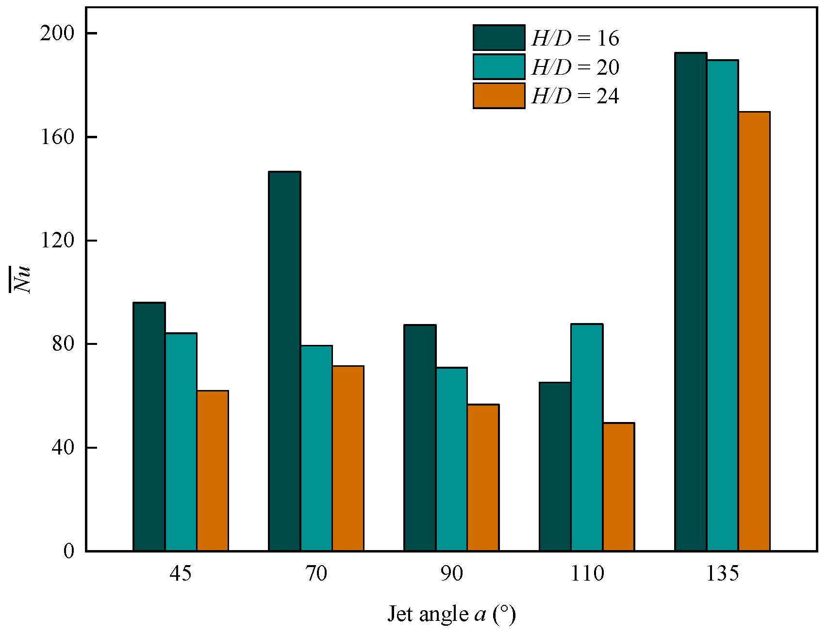
  • By altering the impact angle of the jet on the pressure roller and the heat transfer wall, the jet angle and jet height could modify the wall heat transfer mode and the effective heat transfer area. When jet angle a and jet height H/D were properly combined, high-intensity convective heat transfer could be achieved, increasing Nu ¯ by 2.89 times at the same Reynolds number.
  • The Coanda effect altered the jet’s direction when the small jet angle was directed toward the entrance side of the steel sheet. This caused the high value Numax to appear at the entrance side, increasing the cooling rate in the high temperature region and quenching temperature, which was advantageous for the successful completion of the quenching process.
  • It should be noted that although numerical models have great advantages in theoretical analysis, they idealize the complex industrial environment and can only guide but not replace industrial tests. Therefore, it is the most economical and reliable way to carry out industrial tests on the basis of sufficient theoretical research. In the future, the microstructure evolution and stress–strain behavior of steel sheets during air-jet quenching need to be further studied. This will further promote the production and application of high-flatness UHSS sheets.

Author Contributions

Conceptualization, Y.Y., T.F., G.L. and G.W.; Methodology, Y.Y., T.F., G.L. and G.W.; Software, Y.Y.; Validation, Y.Y.; Formal analysis, Y.Y.; Writing—original draft, Y.Y.; Writing—review and editing, Y.Y. and T.F.; Funding acquisition, T.F. All authors have read and agreed to the published version of the manuscript.

Funding

This work was supported by the National Youth Talent Project of China (QNBJ-2022-02).

Data Availability Statement

The raw data supporting the conclusions of this article will be made available by the authors on request.

Conflicts of Interest

The authors declare that they have no known competing financial interests or personal relationships that could have appeared to influence the work reported in this paper.

References

  1. Li, K.; Yang, T.; Gong, N.; Wu, J.; Wu, X.; Zhang, D.Z.; Murr, L.E. Additive manufacturing of ultra-high strength steels: A review. J. Alloys Compd. 2023, 965, 171390. [Google Scholar] [CrossRef]
  2. Tümer, M.; Schneider-Bröskamp, C.; Enzinger, N. Fusion welding of ultra-high strength structural steels—A review. J. Manuf. Process. 2022, 82, 203–229. [Google Scholar] [CrossRef]
  3. Maraveas, C.; Gernay, T.; Franssen, J. Buckling of steel plates at elevated temperatures: Theory of Perfect Plates vs Finite Element Analysis. In Proceedings of the 2nd International Conference on Structural Safety under Fire and Blast Loading–CONFAB, London, UK, 10 September 2017. [Google Scholar]
  4. Samuel, A.; Prabhu, K.N. Residual Stress and Distortion during Quench Hardening of Steels: A Review. J. Mater. Eng. Perform. 2022, 31, 5161–5188. [Google Scholar] [CrossRef]
  5. Fukuda, H.; Nakata, N.; Kijima, H.; Kuroki, T.; Fujibayashi, A.; Takata, Y.; Hidaka, S. Effects of Surface Conditions on Spray Cooling Characteristics. ISIJ Int. 2016, 56, 628–636. [Google Scholar] [CrossRef]
  6. Zhu, J.; Dou, R.; Hu, Y.; Zhang, S. Wang, Heat transfer of multi-slot nozzles air jet impingement with different Reynolds number. Appl. Therm. Eng. 2021, 186, 116470. [Google Scholar] [CrossRef]
  7. Wan, F.; Wang, Y.; Qin, S. Modeling of Strip Temperature in Rapid Cooling Section of Vertical Continuous Annealing Furnace. J. Iron Steel Res. Int. 2012, 19, 27–32. [Google Scholar] [CrossRef]
  8. Cademartori, S.; Cravero, C.; Marini, M.; Marsano, D. CFD Simulation of the Slot Jet Impingement Heat Transfer Process and Application to a Temperature Control System for Galvanizing Line of Metal Band. Appl. Sci. 2021, 11, 1149. [Google Scholar] [CrossRef]
  9. Perry, K.P. Heat Transfer by Convection from a Hot Gas Jet to a Plane Surface. Proc. Inst. Mech. Eng. 1954, 168, 775–784. [Google Scholar] [CrossRef]
  10. Martin, H. Heat and Mass Transfer between Impinging Gas Jets and Solid Surfaces. In Advances in Heat Transfer; Hartnett, J.P., Irvine, T.F., Eds.; Elsevier: Amsterdam, The Netherlands, 1977; Volume 13, pp. 1–60. [Google Scholar]
  11. Barbosa, F.V.; Teixeira, S.F.C.F.; Teixeira, J.C.F. Convection from multiple air jet impingement—A review. Appl. Therm. Eng. 2023, 218, 119307. [Google Scholar] [CrossRef]
  12. Shukla, A.K.; Dewan, A. Flow and thermal characteristics of jet impingement: Comprehensive review. Int. J. Heat Technol. 2017, 35, 153–166. [Google Scholar] [CrossRef]
  13. Dewan, A.; Dutta, R.; Srinivasan, B. Recent trends in computation of turbulent jet impingement heat transfer. Heat Transf. Eng. 2012, 33, 447–460. [Google Scholar] [CrossRef]
  14. Celik, N. Effects of dimples’ arrangement style of rough surface and jet geometry on impinging jet heat transfer. Heat Mass Transf. 2020, 56, 339–354. [Google Scholar] [CrossRef]
  15. Barbosa, F.V.; Sousa, S.D.T.; Teixeira, S.F.C.F.; Teixeira, J.C.F. Application of Taguchi Method for the Analysis of a Multiple Air Jet Impingement System with and without Target Plate Motion. Int. J. Heat Mass Transf. 2021, 176, 121504. [Google Scholar] [CrossRef]
  16. Barbosa, F.V.; Teixiera, S.F.C.F.; Teixeira, J.C.F. 2D PIV analysis of the flow dynamics of multiple jets impinging on a complex moving plate. Int. J. Heat Mass Transf. 2022, 188, 122600. [Google Scholar] [CrossRef]
  17. Taguchi, G.; Chowdhury, S.; Taguchis, W.Y. Quality Engineering Handbook, 1st ed.; John Wiley & Sons Inc.: Hoboken, NJ, USA, 2005. [Google Scholar]
  18. Attalla, M.; Maghrabie, H.M.; Specht, E. Effect of inclination angle of a pair of air jets on heat transfer into the flat surface. Exp. Therm. Fluid Sci. 2017, 85, 85–94. [Google Scholar] [CrossRef]
  19. Ingole, S.B.; Sundaram, K.K. Experimental average Nusselt number characteristics with inclined non-confined jet impingement of air for cooling application. Exp. Therm. Fluid Sci. 2016, 77, 124–131. [Google Scholar] [CrossRef]
  20. Jensen, M.V.; Walther, J.H. Numerical Analysis of Jet Impingement Heat Transfer at High Jet Reynolds Number and Large Temperature Difference. Heat Transf. Eng. 2013, 34, 801–809. [Google Scholar] [CrossRef]
  21. Shariatmadar, H.; Mousavian, S.; Sadoughi, M.; Ashjaee, M. Experimental and numerical study on heat transfer characteristics of various geometrical arrangement of impinging jet arrays. Int. J. Therm. Sci. 2016, 102, 26–38. [Google Scholar] [CrossRef]
  22. Goodro, M.; Park, J.; Ligrani, P.; Fox, M.; Moon, H. Effects of Mach number and Reynolds number on jet array impingement heat transfer. Int. J. Heat Mass Transf. 2007, 50, 367–380. [Google Scholar] [CrossRef]
  23. Li, W.; Yang, L.; Li, X.; Ren, J.; Jiang, H. Effect of Reynolds Number, Hole Patterns, and Target Plate Thickness on the Cooling Performance of an Impinging Jet Array—Part II: Conjugate Heat Transfer Results and Optimization. J. Turbomach. 2017, 139, 101001. [Google Scholar] [CrossRef]
  24. Ozmen, Y.; Ipek, G. Investigation of flow structure and heat transfer characteristics in an array of impinging slot jets. Heat Mass Transf. 2016, 52, 773–787. [Google Scholar] [CrossRef]
  25. Wen, Z.; He, Y.; Cao, X.; Yan, C. Numerical study of impinging jets heat transfer with different nozzle geometries and arrangements for a ground fast cooling simulation device. Int. J. Heat Mass Transf. 2016, 95, 321–335. [Google Scholar] [CrossRef]
  26. Sarkar, A.; Singh, R.P. Spatial variation of convective heat transfer coefficient in air impingement applications. J. Food Sci. 2003, 68, 910–916. [Google Scholar] [CrossRef]
  27. Attalla, M.; Salem, M. Heat transfer from a flat surface to an inclined impinging jet. Heat Mass Transf. 2014, 50, 915–922. [Google Scholar] [CrossRef]
  28. Li, W.; Xu, M.; Ren, J.; Jiang, H. Experimental investigation of local and average heat transfer coefficients under aninline impinging jet array, including jets with low impingement distance and inclined angle. J. Heat Transf. 2017, 139, 12201. [Google Scholar] [CrossRef]
  29. Garimella, S.V.; Schroeder, V.P. Local heat transfer distributions in confined multiple air jet impingement. J. Electron. Packag. 2001, 123, 165–172. [Google Scholar] [CrossRef]
  30. Ichikawa, Y.; Motosuke, M.; Kameya, Y.; Yamamoto, M.; Honami, S. Three-dimensional flow characterization of a square array of multiple circular impinging jets using stereoscopic PIV and heat transfer relation. J. Vis. 2016, 19, 89–101. [Google Scholar] [CrossRef]
  31. Akansu, Y.E.; Sarioglu, M.; Kuvvet, K.; Yavuz, T. Flow field and heat transfer characteristics in an oblique slot jet impinging on a flat plate. Int. Commun. Heat Mass Transf. 2008, 35, 873–880. [Google Scholar] [CrossRef]
  32. Pawar, S.; Patel, D.K. Study of conjugate heat transfer from the impingement of an inclined free slot jet onto the moving hot surface. Int. Commun. Heat Mass Transf. 2020, 111, 104429. [Google Scholar] [CrossRef]
  33. Mousa, M.H.; Miljkovic, N.; Nawaz, K. Review of heat transfer enhancement techniques for single phase flows. Renew. Sustain. Energy Rev. 2021, 137, 110566. [Google Scholar] [CrossRef]
  34. Ramesh, K.N.; Sharma, T.K.; Rao, G.A.P. Latest Advancements in Heat Transfer Enhancement in the Micro-channel Heat Sinks: A Review. Arch. Comput. Methods Eng. 2021, 28, 3135–3165. [Google Scholar] [CrossRef]
  35. Menter, F.R. Two-equation eddy-viscosity turbulence models for engineering applications. AIAA J. 1994, 32, 1598–1605. [Google Scholar] [CrossRef]
  36. Pulat, E.; Beyazoglu, E. Computational investigation of confined wall inclination effects on impinging jet fluid flow and heat transfer. Int. J. Therm. Sci. 2021, 163, 106749. [Google Scholar] [CrossRef]
  37. ZAhmed, U.; Al-Abdeli, Y.M.; Guzzomi, F.G. Flow field and thermal behaviour in swirling and non-swirling turbulent impinging jets. Int. J. Therm. Sci. 2017, 114, 241–256. [Google Scholar]
  38. Hofmann, H.M.; Kaiser, R.; Kind, M.; Martin, H. Calculations of steady and pulsating impinging jets—An assessment of 13 widely used turbulence models. Numer. Heat Transf. Part B-Fundam. 2007, 51, 565–583. [Google Scholar] [CrossRef]
  39. Qu, S.; Liu, S.; Ong, M.C. An evaluation of different RANS turbulence models for simulating breaking waves past a vertical cylinder. Ocean. Eng. 2021, 234, 109195. [Google Scholar] [CrossRef]
  40. Li, Z.; Lu, X.; Wu, Y.; Han, G. Quantitative investigation of the turbulence model effect on high-pressure-ratio centrifugal compressor performance prediction. Int. Commun. Heat Mass Transf. 2023, 142, 106644. [Google Scholar] [CrossRef]
  41. Tepe, A.Ü.; Uysal, Ü.; Yetişken, Y.; Arslan, K. Jet impingement cooling on a rib-roughened surface using extended jet holes. Appl. Therm. Eng. 2020, 178, 115601. [Google Scholar] [CrossRef]
  42. Huang, H.; Sun, T.; Zhang, G.; Liu, M.; Zhou, B. The effects of rough surfaces on heat transfer and flow structures for turbulent round jet impingement. Int. J. Therm. Sci. 2021, 166, 106982. [Google Scholar] [CrossRef]
  43. Huang, H.; Sun, T.; Zhang, G.; Li, D.; Wei, H. Evaluation of a developed SST k-ω turbulence model for the prediction of turbulent slot jet impingement heat transfer. Int. J. Heat Mass Transf. 2019, 139, 700–712. [Google Scholar] [CrossRef]
  44. Chitsazan, A.; Glasmacher, B. Numerical Investigation of Heat Transfer and Pressure Force from Multiple Jets Impinging on a Moving Flat Surface. Int. J. Heat Technol. 2020, 38, 601–610. [Google Scholar] [CrossRef]
  45. Kadiyala, P.K.; Chattopadhyay, H. Numerical Analysis of Heat Transfer from a Moving Surface Due to Impingement of Slot Jets. Heat Transf. Eng. 2018, 39, 98–106. [Google Scholar] [CrossRef]
  46. Zhang, R.; Li, Z.; Zhang, Y.; Chen, D.; Yuan, G. Numerical investigation of jet layout for annular jet cooling on a steel tube. Appl. Therm. Eng. 2022, 213, 118825. [Google Scholar] [CrossRef]
  47. Gardon, R.; Akfirat, J.C. Heat transfer characteristics of impinging two-dimensional air jets. J. Heat Transf. 1966, 88, 101–107. [Google Scholar] [CrossRef]
  48. Tepe, A.Ü.; Yetişken, Y.; Uysal, Ü.; Arslan, K. Experimental and numerical investigation of jet impingement cooling using extended jet holes. Int. J. Heat Mass Transf. 2020, 158, 119945. [Google Scholar] [CrossRef]
  49. Jambunathan, K.; Lai, E.; Moss, M.; Button, B.L. A review of heat transfer data for single circular jet impingement. Int. J. Heat Fluid Flow 1992, 13, 106–115. [Google Scholar] [CrossRef]
Figure 1. Roller-constrained slot air-jet quenching equipment. (a) Three-dimensional model, (b) partial schematic diagram.
Metals 14 00377 g001
Figure 2. Two-dimensional fluid calculation domain.
Metals 14 00377 g002
Figure 3. Grid independence test under different grid numbers (Re = 41,076, H/D = 20, a = 90°).
Metals 14 00377 g003
Figure 4. The computational domain of the verification model.
Metals 14 00377 g004
Figure 5. Comparison of simulation and experimental data, adapted from Ref. [47].
Metals 14 00377 g005
Figure 6. Jet deflection caused by a stepped confined wall (Re = 41,076, H/D = 16, a = 90°). (a) Turbulent kinetic energy (K) contours and stream traces, (b) dimensionless pressure (Cp) contours and stream traces.
Metals 14 00377 g006
Figure 7. Velocity (U) contours and stream traces at different dimensionless heights (Re = 41,076, a = 90°). (a) H/D = 16, (b) H/D = 20, (c) H/D = 24.
Metals 14 00377 g007
Figure 8. Velocity (U) contours and stream traces at different dimensionless heights (Re = 41,076, a = 70°). (a) H/D = 16, (b) H/D = 20, (c) H/D = 24.
Metals 14 00377 g008
Figure 9. Velocity (U) contours and stream traces at different dimensionless heights (Re = 41,076, a = 110°). (a) H/D = 16, (b) H/D = 20, (c) H/D = 24.
Metals 14 00377 g009
Figure 10. Velocity (U) contours and stream traces at different dimensionless heights (Re = 41,076, a = 45°). (a) H/D = 16, (b) H/D = 20, (c) H/D = 24.
Metals 14 00377 g010
Figure 11. Velocity (U) contours and stream traces at different dimensionless heights (Re = 41,076, a = 135°). (a) H/D = 16, (b) H/D = 20, (c) H/D = 24.
Metals 14 00377 g011
Figure 12. Dimensionless pressure (Cp) contours and stream traces (Re = 41,076, H/D = 16, a = 135°).
Metals 14 00377 g012
Figure 13. Effect of Reynolds number on wall heat transfer. (a) Effect of Reynolds number Re on the local Nusselt number Nux (H/D = 16, a = 70°, 90°, 135°), (b) distribution of exponent m under different configurations ( Nu ¯ Rem).
Metals 14 00377 g013
Figure 14. Influence of dimensionless height H/D and jet angle a on Nu ¯ (Re = 41,076).
Metals 14 00377 g014
Table 1. Geometrical parameter.
A [mm]B [mm]C [mm]D [mm]E [mm]F [mm]G [mm]H [mm]
3020401.57557.5100≥24
Table 2. The specific values of constants in SST models (Reprinted with permission from ref. [46]. 2024 Elsevier).
α1α2β1β2β*σk1σk2σω1σω2
5/90.443/400.08280.090.8510.50.856
Table 3. The chemical composition of Q1100.
CSiMnCrBSP
0.17–0.200.20–0.300.80–1.200.40–0.600.001–0.002<0.005<0.010
Table 4. The location and value of maximum Numax at each jet angle (Re = 41,076).
Jet Angle [°]X Coordinate of Maximum Numax [m]Value of Maximum NumaxH/D
450.19024016
700.11046616
900.03414816
1100.03729220
1350.04343816
Disclaimer/Publisher’s Note: The statements, opinions and data contained in all publications are solely those of the individual author(s) and contributor(s) and not of MDPI and/or the editor(s). MDPI and/or the editor(s) disclaim responsibility for any injury to people or property resulting from any ideas, methods, instructions or products referred to in the content.

