Abstract
This study investigated the influence of Fe content on the microstructure and mechanical properties of Ti–6Al–4V(TC4) + 25Ti alloys prepared by low-energy-density direct energy deposition (DED) technology. With the incorporation of the Fe elements, the α-Ti phases exhibited significant changes in size and morphology, while the numerous β-Ti phases and some triclinic-Ti precipitates were retained. With the refinement of the α-Ti phase, retainment of the β-Ti phase and the presence of triclinic-Ti precipitates, the mechanical properties of DED samples can be significantly improved compared with DED TC4 alloys. The room-temperature mechanical property tests showed that the ultimate tensile strength (UTS) of 3Fe + TC4 + 25Ti achieved 1298.64 ± 5.26 MPa with an elongation of 4.82% ± 0.20%, and the maximum elongation of 1Fe + TC4 + 25Ti reached 10.82% ± 0.82% with a UTS of 1076.95 ± 11.69 MPa. The strengthening mechanism of DED Ti-Al-V-Fe alloys were further discussed, providing new insights into the microstructure control and the composition design of additive manufacturing of Ti alloys.
1. Introduction
Titanium (Ti) alloys are extensively utilized in aerospace applications due to their low modulus, high specific strength, exceptional fatigue resistance, and corrosion resistance [1]. Among the various Ti alloys, α + β Ti alloys have garnered significant attentions due to their relatively superior comprehensive properties and excellent processing performance [2,3]. Specifically, by precisely controlling the elemental composition, a high-performance TC4 (Ti–6Al–4V wt%) alloy was successfully developed in 1954. This alloy has outstanding mechanical properties and currently accounts for over half of the total production of various engineering parts/products based on titanium alloys [4]. Recently, the increasing demand for complex engineering parts has sparked a surge of interest in the additive manufacturing (AM) of TC4 alloys [5,6]. Among the different AM technologies, direct energy deposition (DED) technology is characterized as a fast process with high efficiency, and thus has become the focus of attention, where the control of the microstructure and the strengthening mechanism of DED-Ti alloys have been investigated widely [7,8,9,10].
In Ti alloys, iron (Fe) is an alloying element with a strong ability to stabilize the β-Ti phase and also exerts a significant strengthening effect on the Ti matrix [11,12]. Among the various alloying elements, e.g., Nb, V, Fe, Co, and other elements, the incorporation of Fe in pure Ti can greatly enhance the ultimate tensile strength (UTS) at room temperature [13]. For instance, X. Wang et al. added Fe elements into the AM-prepared TC4 samples that could induce a transformation from the columnar β grains into the equiaxed grains, accompanied by the formation of some ω phases and Ti–Fe precipitates. This would lead to a uniformly distributed ultrafine structure in the as-prepared samples after fabrication. Meanwhile, these studies have also demonstrated that both the compressive strength and deformability of DED TC4-3wt%Fe samples can be significantly improved compared with the TC4 samples [14,15]. Moreover, the utilization of Fe powder as a readily available and cost-effective raw material further contributes to its practicality [16].
Nevertheless, with the rapid cooling rate and large thermal gradient inherent in AM technology, the addition of a high Fe content often results in the poor tensile plasticity of as-prepared Ti alloys [8,17]. To address this issue, several strategies have been developed. J. Zhang et al. proposed an effective approach that involved the incorporation of Fe into an alloy with commercially pure titanium (CP-Ti) powder [18]. Through laser power bed fusion (L-PBF) processing of mixed powders of Fe2O3, CP-Ti, and TC4, the diluted Al and V contents in the Ti matrix (compared with TC4) can reduce the heterogeneity between the two phases and contribute to the plasticity, while the O and Fe elements, respectively, occupy the interstitial site of the hexagonal close-packed (HCP) α-Ti phase and the substitution site of the body-centered cubic (BCC) β-Ti phase [16] to produce a solid solution strengthening effect, both of which contribute to a good synergy between the strength and ductility of L-PBF alloys. Alternatively, optimizing the energy density parameters during preparation can also be considered [19,20]. M. Chen et al. reduced the energy density parameters (in both L-PBF and DED) and incorporated a specific amount of Ti; both the tensile strength and plasticity of the Ti–Al–V–Fe alloy based on DED could be improved compared with the TC4 alloy [19].
However, the strengthening mechanism of Fe elements added to Ti–Al–V alloys prepared by low-energy-density DED, especially its impact on the microstructure of the α/β-Ti phase and precipitates within the grain, remains largely ambiguous. For example, in as-fabricated samples, despite similar grain sizes, the sub-morphology and size of the α/β-Ti phases, along with the precipitates, can exhibit significant variations in mechanical properties. These variations may give rise to basketweave or lamellar structures and consequently lead to distinct mechanical properties. Therefore, a comprehensive comprehension of the influence of the Fe content on the size and morphology of α/β-Ti phases and the formation of precipitates would benefit the design of high-performance TC4 alloys via AM methods.
In this study, we investigate the microstructure within the grain and the mechanical properties of 25Ti + TC4 alloys with added Fe, prepared by DED at a low energy density. By analyzing the α/β-Ti phases and precipitates in the as-fabricated alloys, the effects of the Fe elements on mechanical properties of the Ti–Al–V–Fe alloys were systematically explored.
2. Experimental Details
The prefabricated spherical TC4 powder (diameter: 60~150 μm), spherical CP-Ti powder (diameter: 40–150 μm), and spherical Fe powder (diameter: 40–150 μm) were mixed with a planetary ball mill (QM-3SP4) at 200 r/min for a single cycle of 30 min and 6 cycles to obtain the 1Fe + TC4 + 25Ti (wt%), 3Fe + TC4 + 25Ti (wt%), and 5Fe + TC4 + 25Ti (wt%) alloy powders as the raw material. BLT-C600 (Bright Laser Technologies. Ltd., Xi’an, China) was used for the DED fabrication of the 1Fe + TC4 + 25Ti, 3Fe + TC4 + 25Ti, 5Fe + TC4 + 25Ti, and TC4 alloys. During the DED process, the chamber was filled with high-purity argon to avoid oxidation (O2 content < 100 ppm), and laser printing was performed on a 15 mm thick TC4 substrate. The Ti–Al–V–Fe alloying process is illustrated in Figure 1. The main deposition parameters include the laser’s power (W), the scan speed of the laser (s), the thickness of the deposition layer (t), and the width of the hatch (h), as listed in Table 1. For each fabrication, the volumetric energy density can be obtained from Equation (1) [8,19].

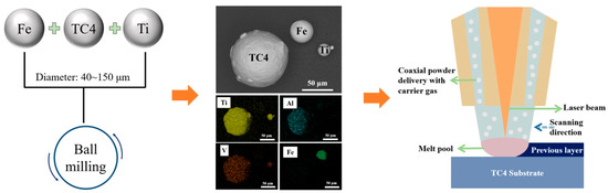

Table 1.
Processing parameters for DED.
Table 1.
Processing parameters for DED.
| Laser Power (W) | Scan Speed (mm/s) | Thickness of the Layer (mm) | Hatch (mm) | Volumetric Energy Density (J/mm3) |
|---|---|---|---|---|
| 800 | 11.67 | 0.40 | 1.30 | 131 |
Figure 1.
Schematic illustration of the fabrication process of the Ti–Al–V–Fe alloys.
Figure 1.
Schematic illustration of the fabrication process of the Ti–Al–V–Fe alloys.
The as-fabricated samples had a size of 30 mm × 30 mm × 20 mm. Subsequent processing samples were all taken from the central portion of the as-fabricated samples, aiming to minimize potential variations arising from the disparate sampling locations. The samples were first ground to a smooth surface with 180–3000 mesh sandpapers, and finally polished to a mirror surface with a silicon dioxide suspension. The samples were then etched with Kroll’s reagent (10 mL HF, 30 mL HNO3, and 130 mL H2O) until the surface lost its metallic luster. The microstructures were examined using a scanning electron microscope (SEM (Thermo Fisher Scientific Inc., Waltham, MA, USA); Quanta 650) and a transmission electron microscope (TEM (Lasertec Corporation, Yokohama, Japan); Tecnai G2 F20 S-TWIN) with a high-angle annular dark field detector and a bright-field detector. TEM samples were first ground to 100 µm thick and then polished in the liquid injection (120 mL CH3OH, 68 mL C4H10O, and 12 mL HClO4) by applying a twin-jet polisher. The operando X-ray diffraction experiments were performed on a PANalytical X’Pert PRO. The sizing of the phases and the quantification of the precipitates were conducted utilizing the open-source software ImageJ 1.53t.
The as-fabricated bulk samples were cut into dog-bone-like samples with a gauge length of 12.8 mm, a width of 3.2 mm, and a thickness of 1.5 mm for tensile testing. The tensile test was conducted using the MTS E45 (Mechanical Testing & Simulation Ltd., Xianyang, China), at a strain rate of 5 × 10⁻⁴ s−1. The yield strength (YS) was calculated using the 0.2% offset method. At least three samples were prepared for tensile tests of each alloy to ensure the consistency and repeatability of the measured results.
3. Results and Discussion
3.1. Effects of Fe on the α/β-Ti Phases
The microstructures of Ti alloys fabricated by common methods can generally be classified into three categories, i.e., the stable near-α-Ti phases (including the α, α’, and α” phases) [21,22,23], the stable near-β-Ti phases (including the β and β’ phases) [4,24], and diverse precipitates [25,26]. In this study, the added Fe element was a β-Ti phase stabilizing element. The relative ability of Fe elements to stabilize the β-Ti phase can be evaluated by the [Mo]eq proposed by Rosenberg [27,28]; see Equation (2)
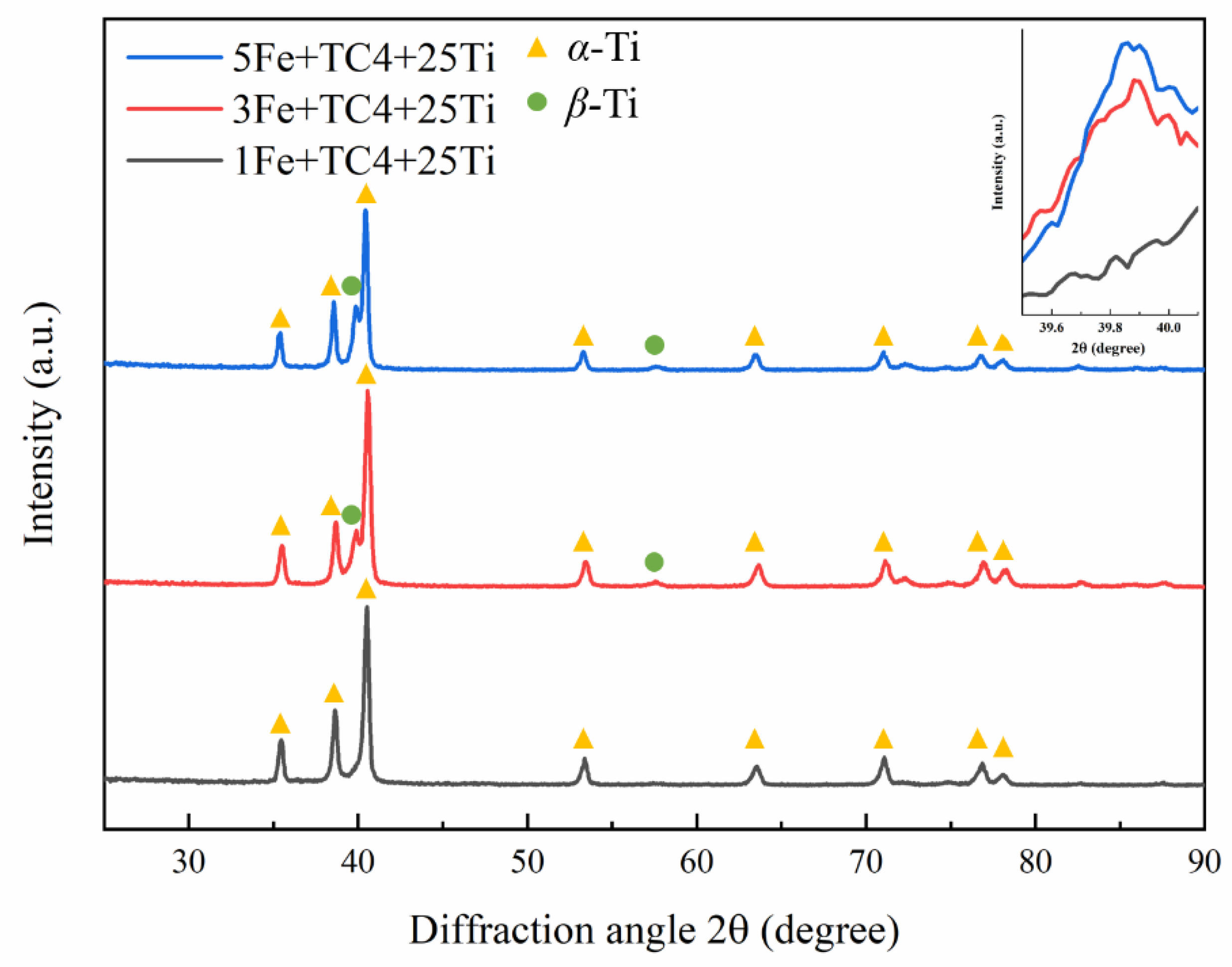
where the parenthetical element symbols indicate the mass fraction of each element. The calculation formula of [Mo]eq is a theoretical equation used to evaluate the relative stability of the β-Ti phases with various elements. Therefore, a higher [Mo]eq value, calculated on the basis of the alloy’s composition, indicates that, theoretically, there should be a greater amount of the β-Ti phase retained in the alloy [27]. From Equation (2), the [Mo]eq of 1Fe + TC4 + 25Ti, 3Fe + TC4 + 25Ti, and 5Fe + TC4 + 25Ti alloys studied here were calculated to be 4.10, 8.04, and 11.98, respectively. Compared with 2.84 for the TC4 alloy, the [Mo]eq of our alloys showed a marked increase with the increase in the Fe content, suggesting the enhanced formability of β-Ti in theory, as demonstrated by the XRD of these three as-fabricated alloys in Figure 2. In the 1Fe + TC4 + 25Ti alloy (black line), the characteristic peak from β-Ti can be hardly detected, while, with an increase in the Fe content, the characteristic peak of β-Ti showed up and became stronger in the 3Fe + TC4 + 25Ti (red line) and 5Fe + TC4 + 25Ti alloys (blue line). The XRD result for the 5/3/1Fe + TC4 + 25Ti sample, obtained at a diffraction angle ranging from 39.5° to 40.5°, is presented in an enlarged format in the upper right corner of Figure 2. The absence of a β-Ti peak in the 1Fe + TC4 + 25Ti sample is evident, while the intensity of the 5Fe + TC4 + 25Ti sample slightly surpassed that of the 3Fe + TC4 + 25Ti sample. This observation suggests a higher retainment of the β-Ti phase in the 5/3Fe + TC4 + 25Ti alloy compared with its presence in the 1Fe + TC4 + 25Ti alloy. This is consistent with the trend obtained from the theoretical calculations of [Mo]eq.
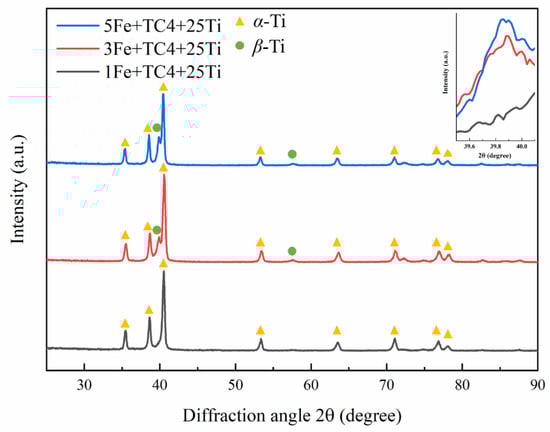
Figure 2.
The X-ray diffraction (XRD) patterns of 1Fe + TC4 + 25Ti, 3Fe + TC4 + 25Ti, and 5Fe + TC4 + 25Ti alloys.
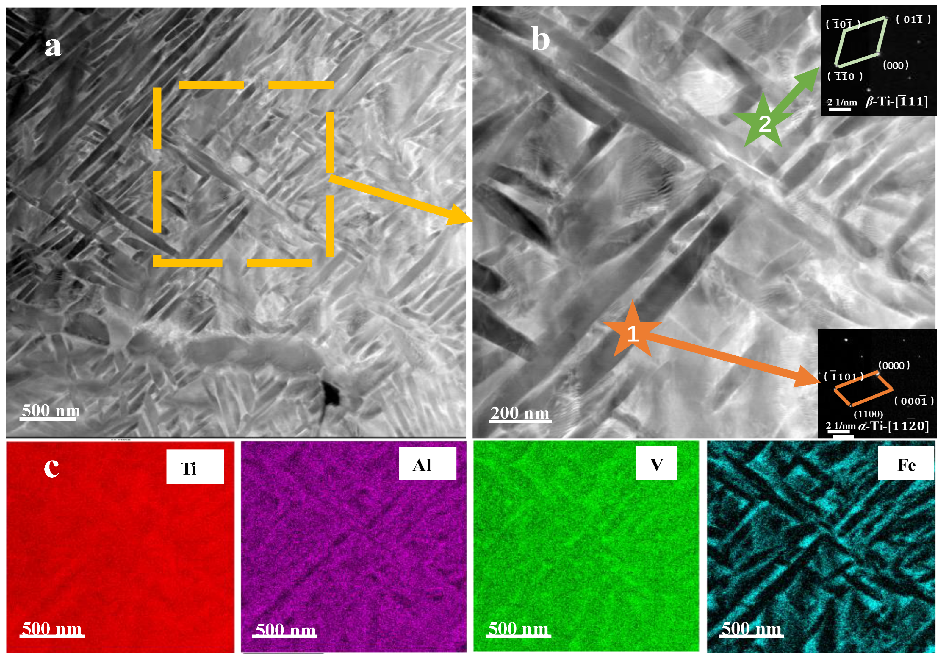
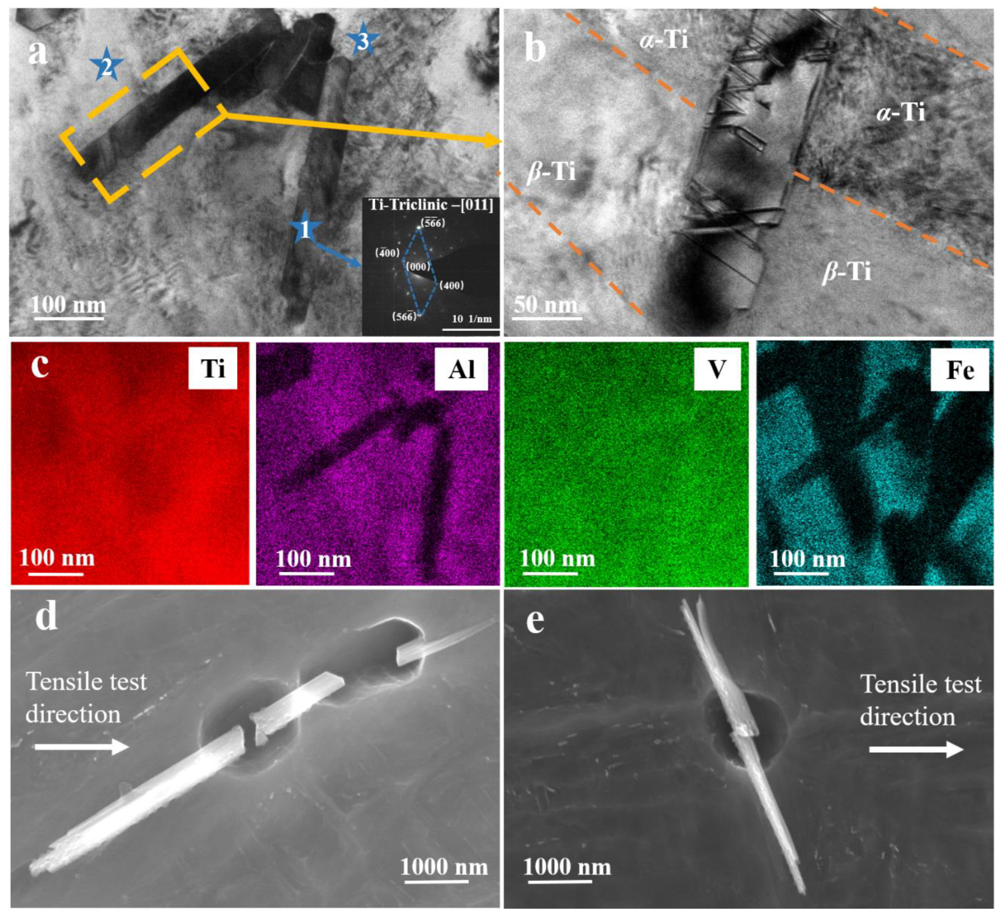
The microstructures of the as-fabricated 5Fe + TC4 + 25Ti alloy are depicted in Figure 3a,b, captured at varying magnifications. The as-fabricated 5Fe + TC4 + 25Ti alloy possesses a typical duplex phase structure. TEM images of the morphologies and the corresponding diffraction patterns indicate that the lath-shaped structure is the α-Ti phase with a zone axis of [110] (Figure 3b), while the irregular phases between different α-Ti laths are β-Ti phases with a zone axis of [11] (Figure 3b). The α-Ti phases are predominantly oriented either parallel or perpendicular to one another, with an average length of 615.52 nm and an average width of 90.58 nm, showing an aspect ratio of 7.27. The β-Ti phase does not have a specific morphology, and mainly exists as irregular block-shaped phases between different α-Ti laths. The EDS mapping in Figure 3c demonstrates that the Al, V, and Fe elements have different degrees of segregation among the two phases, where Al elements mainly exist in the α-Ti phase, while the V and Fe elements mainly exist in the β-Ti phase. This is consistent with the general understanding of Al as an α-Ti stabilization element and V and Fe elements as β-Ti stabilization elements. The elemental content in the α-Ti and β-Ti phases was quantitatively analyzed through experimental tests. The obtained results revealed a relatively high concentration of Al elements in the α-Ti phase (5.62 ± 1.08 wt%), the V elements exhibited a moderate concentration (3.50 ± 2.15 wt%), and the Fe elements displayed an extremely low concentration (0.12 ± 0.05 wt%); in the β-Ti phase, a slight decrease in the Al content (3.13 ± 0.74 wt%) was observed, while there was a marginal increase in the V content (5.71 ± 2.78 wt%). The Fe content exhibited the highest concentration (5.50 ± 1.19 wt%). It was noticed that the degree of Fe’s segregation in the β-Ti phase was significantly higher than that of the V elements, suggesting that Fe elements are more effective β-Ti phase stabilizers than V elements.

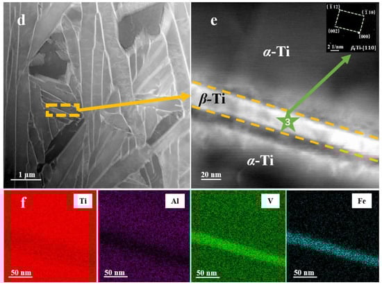
Figure 3.
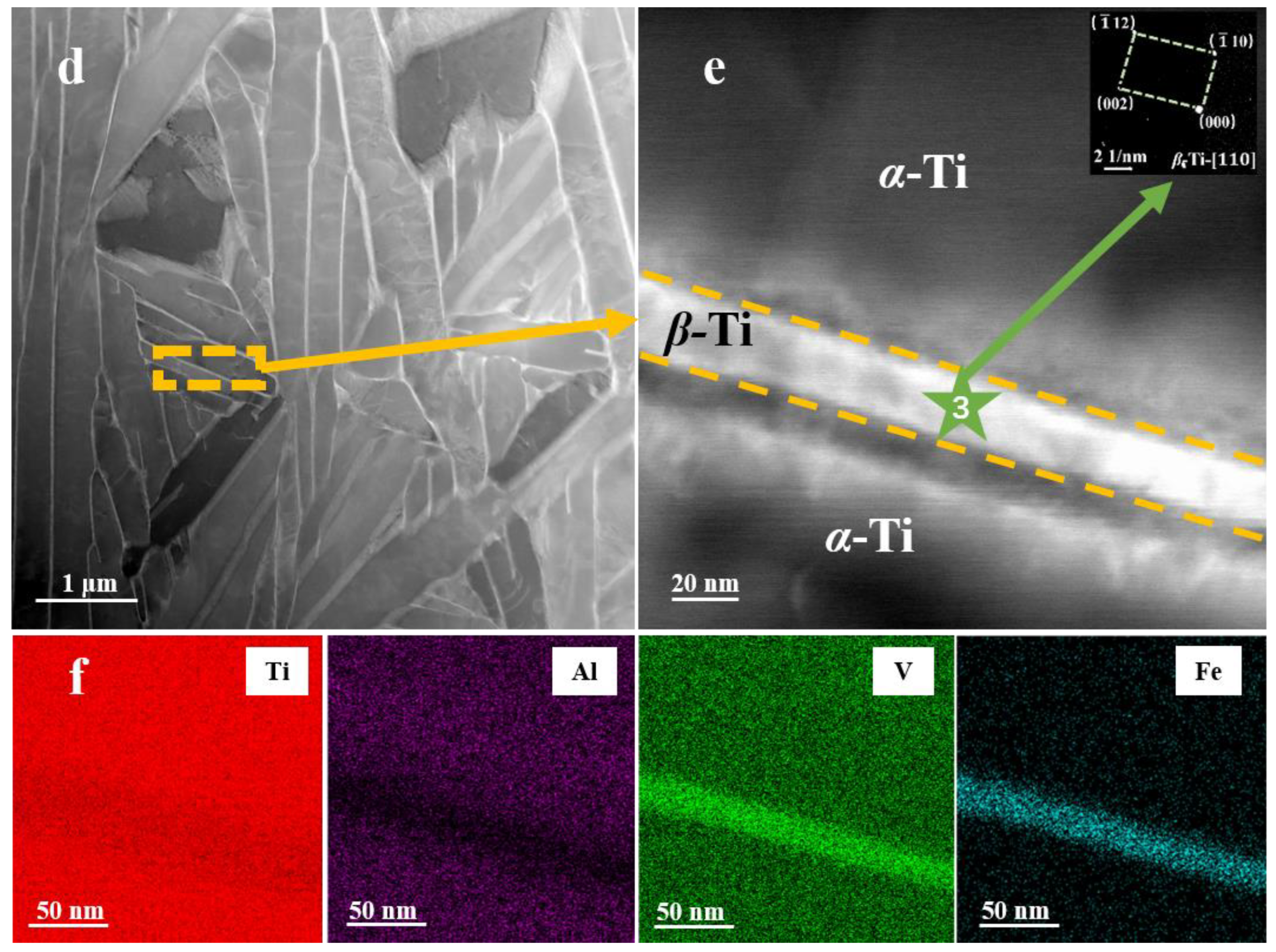
Microstructural characterization of the 5Fe + TC4 + 25Ti and 1Fe + TC4 + 25Ti alloys. (a) Scanning transmission electron microscopy (STEM) image of the α-Ti and β-Ti phases in the 5Fe + TC4 + 25Ti alloy. (b) Zoomed-in image of (a). (c) EDS mapping showing the distribution of Ti, V, Al, and Fe in (b). (d) STEM image of the 1Fe + TC4 + 25Ti alloy. (e) Zoomed-in image and EDS mapping (f) showing the β-Ti phase and its distribution of elements.
With a gradual decrease in the Fe content, the two-phase morphology was effectively maintained in the 3Fe + TC4 + 25Ti alloy, while it became nearly imperceptible in the 1Fe + TC4 + 25Ti alloy. As shown in Figure 3d, the α-Ti phases in 1Fe + TC4 + 25Ti alloy retained the lath shape, but its length, width, and aspect ratio increased significantly, with an average length of 5900.44 nm, an average width of 423.54 nm, and an aspect ratio of 14.13. Compared with the highly orientated α-Ti laths in the 5Fe + TC4 + 25Ti alloy, the α-Ti laths in the 1Fe + TC4 + 25Ti alloy showed a relatively random arrangement with different orientations (Figure 3d,e). The β-Ti phases in the 1Fe + TC4 + 25Ti alloy mainly existed as very thin strips (with an average thickness of 15.83 ± 1.38 nm) between the α-Ti laths, differing from the block-shaped β-Ti in the 5Fe + TC4 + 25Ti alloy. The EDS mapping in Figure 3f demonstrates that the Al, V, and Fe elements had different degrees of segregation in these two phases. The observed morphology indicated that variations in the Fe content exerted a direct influence on the β-Ti phase, leading to contraction or expansion of its area. These observations indicated that the addition of Fe not only changed the grains’ morphology from columnar grains into equiaxed grains, but, more importantly, it can help to refine the structure of the α-Ti phase [29,30].
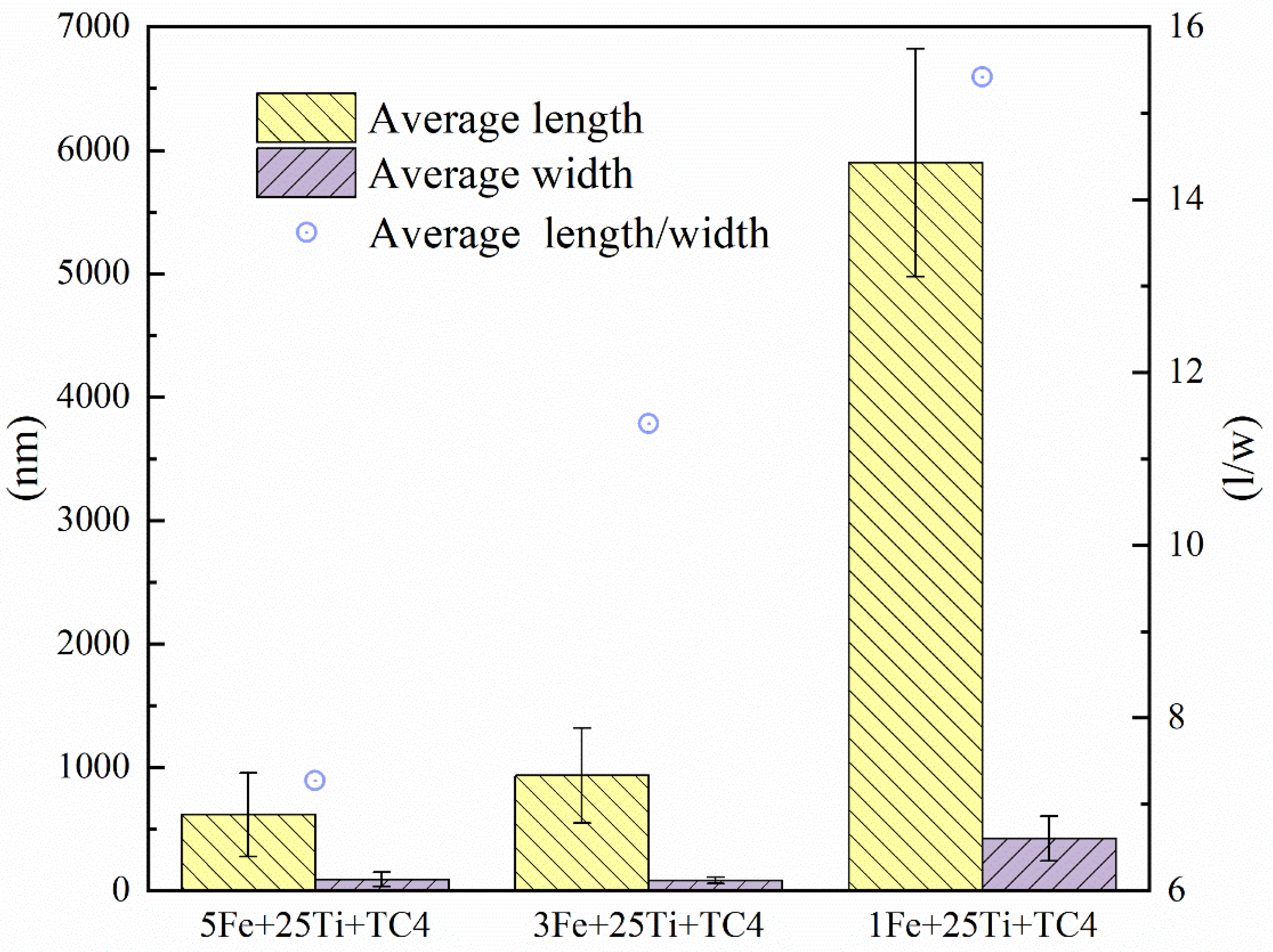
Although the unique preparation techniques used in DED technology, such as extremely rapid cooling rates, resulting in disparities in the sizes the of α-Ti and β-Ti phases within samples composed of identical elements, these discrepancies were even more pronounced with varying Fe contents. Consequently, Figure 4 further quantifies the size distribution and aspect ratio of α-Ti laths with a change in the Fe content. Clearly, the α-Ti laths in the 5Fe + TC4 + 25Ti and 3Fe + TC4 + 25Ti alloys were much smaller than those in the 1Fe + TC4 + 25Ti alloy (Figure 4). Although the average width and morphology of the α-Ti laths in 5Fe + TC4 + 25Ti and 3Fe + TC4 + 25Ti alloys were similar, the average length and aspect ratio of the α-Ti laths in the 5Fe + TC4 + 25Ti alloy were much smaller than those in the 3Fe + TC4 + 25Ti alloy, both of which are greatly smaller than those of the 1Fe + TC4 + 25Ti alloy. These quantifications indicated that an increase in the Fe content could significantly refine the size of the α-Ti laths in our alloys.

Figure 4.
Average length, width, and aspect ratio of the α-Ti phase in 1Fe + TC4 + 25Ti, 3Fe + TC4 + 25Ti, and 5Fe + TC4 + 25Ti alloys.
Liquid Ti typically experiences sequential solid-state transformations of liquid → β-Ti phase →α-Ti phase [31] as it cools from high temperatures to room temperature. If there are no β-Ti phase stabilizing elements in the alloy (such as Fe, V, etc.), usually, there will be few β-Ti phases left at room temperature [32]. The addition of Fe, as a strong β-Ti stabilizing element, can stabilize the β-Ti phase and thus help to preserve more of the β-Ti phase during the solidification process. More specifically, Fe atoms occupy the substitution position of β-Ti’s BCC structure, which increases the energy barrier of the β-Ti phase to α-Ti phase transformation (from 882 kJ/mol to 924 kJ/mol), so that more β-Ti phases can be retained in the as-fabricated samples [13,27]. Therefore, a duplex phase structure with thin α-Ti laths can be obtained with an increase in the Fe content. The essence lies in the Fe element’s prevention of the transformation of the β-Ti phase into α-Ti phase in the matrix, thereby retaining more of the β-Ti phase and resulting in the refined microstructure of the α-Ti phase. These differences indicate that an increase in the Fe content (below 3 wt%) can largely promote the fast growth of the β-Ti phase during DED, which, with the finer structures, may lead to enhanced mechanical properties, as discussed later.
3.2. Effects of Fe on Precipitates
Except for the α-Ti/β-Ti duplex structures, the presence of precipitates was also observed in these three as-deposited alloys, as shown in the SEM images in Figure 5a–c (characterized by their bright contrast). In the 5Fe + TC4 + 25Ti alloy, the quantification of precipitates was relatively small (only μm−2), without a preferential distribution in the alloy’s matrix. In the 3Fe + TC4 + 25Ti alloy, the precipitates had a large quantification of μm−2, and were distributed both at the grain boundary (see the dotted lines) and in the grain’s interior. By contrast, the precipitates in the 1Fe + TC4 + 25Ti alloy showed a clear tendency to aggregate along the grain boundaries, with a quantification of μm−2. The statistical measurements in Figure 5d further show that the density of the precipitates in the 5Fe + TC4 + 25Ti sample was much lower than that of the 3Fe + TC4 + 25Ti and 1Fe + TC4 + 25Ti samples. These observations suggested that increasing the Fe content can effectively promote the formation of precipitates. The precipitates tends to precipitate preferentially along the grain boundary, then gradually appear inside the grain with further increased in Fe elements. When the Fe content was above 3 wt%, the content of the precipitate decreased significantly.
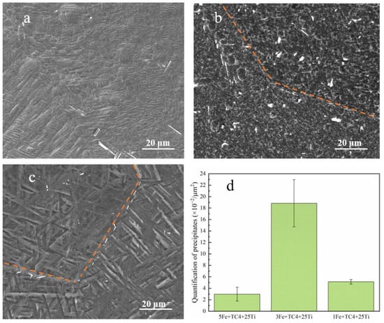
Figure 5.
Scanning electron microscope (SEM) images of (a) 5Fe + TC4 + 25Ti, (b) 3Fe + TC4 + 25Ti, and (c) 1Fe + TC4 + 25Ti. (d) Quantification of the precipitates in each sample.
TEM characterizations indicated that the precipitates in these three alloys were similar. Figure 6 presents the typical precipitates in the 3Fe + TC4 + 25Ti alloy, as an example. The precipitate mainly existed in the form of needles or short slat-like shapes, consistent with the SEM observations in Figure 5. On the basis of the diffraction patterns, the crystal structure of the precipitate could be identified as the triclinic-Ti phase, with the lattice parameters of a = 11.63Å, b = 12.22Å, c = 12.31Å; α = 93.29°, β = 90.68°, and ɣ = 92.23°, consistent with a previous study [33]. The EDS mapping in Figure 6b and the element point scanning in Table 2 show that the precipitate was enriched in V elements, with little of the Fe elements. The mass fractions of the Al and Fe elements in the precipitate (see Spot 1) were significantly lower than those in the α-Ti phase (Spot 2) and β-Ti phase (Spot 3); while the V content in the precipitate is higher than the corresponding content in the α-Ti phase, but similar to the content in the β-Ti phase. This means that the triclinic Ti phase basically did not contain strong stabilizing elements, which may have resulted in the triclinic Ti phase having lower strength but better deformability than the α-Ti and β-Ti phases. This speculation was confirmed by the deformation morphologies of the 3Fe + TC4 + 25Ti alloy. As shown in Figure 6b, high-density dislocations were introduced into the triclinic Ti precipitate, while the triclinic Ti precipitate was also deformed by twins and dislocations. The easy deformation of the triclinic-Ti precipitate can greatly release the concentration of stress caused by the accumulation of dislocations at the interface of the triclinic Ti precipitate with the α/β-Ti phase. With a certain amount of triclinic Ti precipitate, the deformation-induced plastic localization could be largely alleviated, contributing to enhanced plasticity.

Figure 6.
Microstructural characterization of the precipitate in the 3Fe + TC4 + 25Ti alloy. (a) STEM image of the triclinic Ti phase in the 3Fe + TC4 + 25Ti alloy. (b) Zoomed-in image of (a). (c) EDS maps showing the distribution of Ti, V, Al, and Fe in (a). (d,e) The fracture and deformation of the precipitate after tensile testing, respectively.
Table 2.
Chemical composition (wt%) of each spot.
The presence of triclinic Ti phase precipitates in high-strength Ti alloys prepared by AM has not been documented in previous studies. The formation of triclinic Ti phases may be caused by the combination of two factors: the addition of a certain amount of Fe elements and the lower energy density applied in this experiment [8]. With a low energy density, a high-temperature gradient could be generated in the deposited sample during fabrication [34]. According to Fourier’s law of heat conduction (Equation (3)), the heat transferred per sectional area per unit of time is proportional to the rate of change in temperature perpendicular to the cross-section [35]
where is the heat flux (i.e., the thermal flux in units of Watts per square meter), is the gradient of the temperature, and is the proportional coefficient. Therefore, a lower energy density during preparation would result in a higher temperature gradient and thereby an enhanced heat flux density, resulting in a shorter molding time for the sample. Moreover, the diffusion rate of Fe atoms would be higher than the self-diffusion rate of Ti atoms, so the Fe atoms could rapidly occupy the substitution positions in place of the Ti atoms, resulting in the formation of triclinic Ti precipitates dominated by pure Ti atoms [36].
3.3. Mechanical Properties
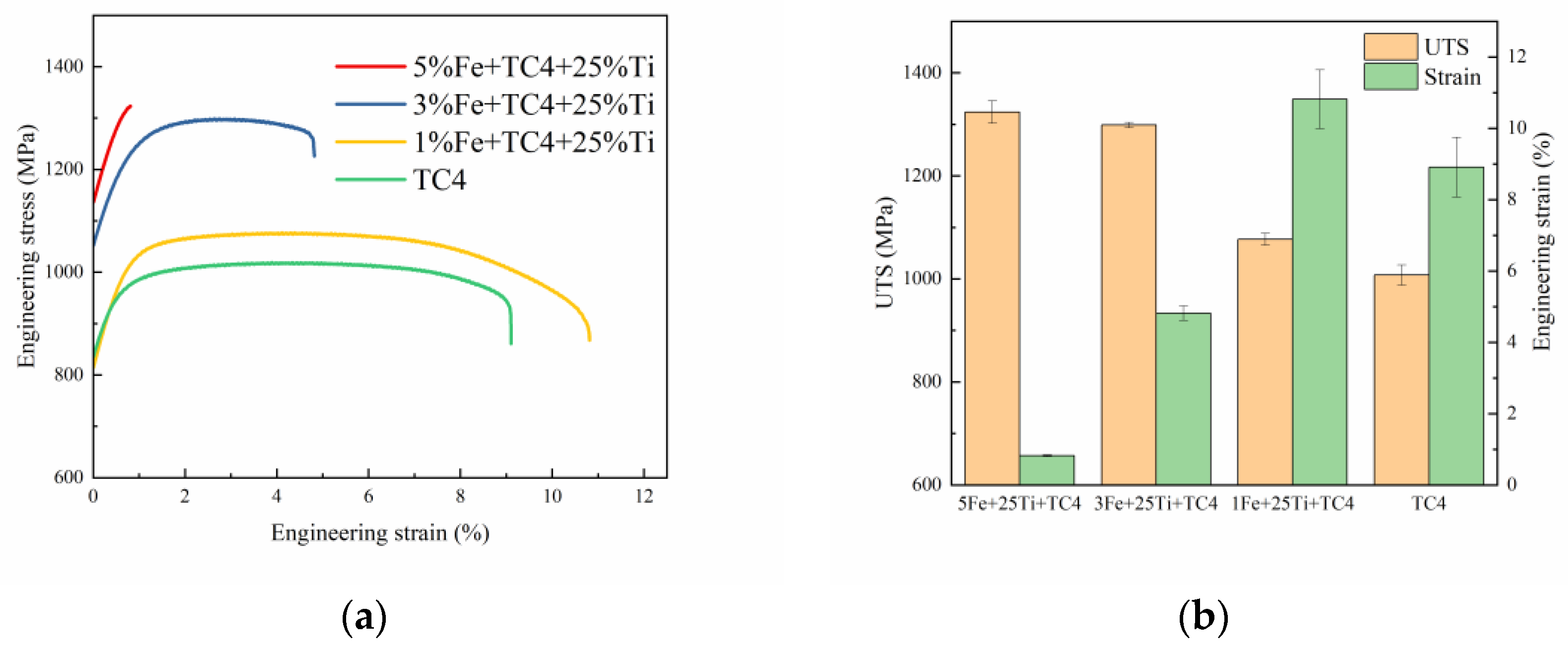
The mechanical properties of the as-fabricated alloys were further evaluated by a tensile test at room temperature. Figure 7a presents the tensile stress–strain curves of different samples. The as-fabricated TC4 showed low strength and acceptable elongation; with the addition of Fe elements, the strength of the as-fabricated alloy exhibited a net increase, at some expense of ductility. The statistical measurements in Figure 7b show that the UTS of the 5Fe + TC4 + 25Ti alloy achieved 1323.75 ± 21.74 MPa, with a total elongation of merely 0.81% ± 0.02%, while the UTS of the 1Fe + TC4 + 25Ti and TC4 alloys was merely 1076.95 ± 11.69 MPa and 1007.41 ± 19.43 MPa, respectively, with a total elongation of 10.82% ± 0.82% and 8.91% ± 0.84%, respectively. The 3Fe + TC4 + 25Ti alloy showed a moderate strength of 1298.64 ± 5.26 MPa and acceptable elongation of 4.82% ± 0.20%. Table 3 summarizes the mechanical properties of the Ti alloys made by different manufacturing methods. These results suggested that a combination of high strength and acceptable elongation can be obtained in the TC4 + 25Ti alloy by the appropriate addition of Fe.
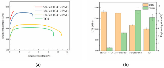
Figure 7.
The quasi-static mechanical properties and the microhardness results of the 5/3/1Fe + TC4 + 25Ti alloys and the TC4 alloy. (a) The strain–stress curves; (b) histogram of the mechanical properties.
As mentioned above, the addition of Fe elements makes the samples’ microstructure show three characteristics, namely, the refinement of the α-Ti phase’s microstructure, the retainment of the β-Ti phase, and the appearance of triclinic Ti precipitates. Therefore, the origin of the enhanced strength of Fe-added DED samples should be composed of three parts: the strength caused by the refinement of the α-Ti phase, the solid-solution strengthening induced by the addition of Fe, and the strengthening from the shear-resistant precipitates. In the case of Ti alloys, the refinement of the α-Ti phase contributed to the increase in strength can be described by the well-known Hall–Petch relationship as shown in Equation (4) [20].
where is the strengthening constant (=247 ) and is the average width of the α-Ti phase. The solid-solution strengthening () can be expressed by Equations (5)–(7) [37].
where G is the shear modulus, and (=110 GPa) and (=0.34) are the elastic modulus and Poisson ration, respectively. is the Taylor factor (=5), is the interaction parameter, represents the total atomic fraction of all of the alloying elements, and a is the lattice constant (=0.2942 nm).
The contribution of shear-resistant precipitates to strengthening () can be estimated via Equations (8)–(10) [38].
where is the number of particles per unit of area of the precipitates, is the mean thickness of the precipitate, is the mean diameter of the precipitate, is the volume fraction of the precipitate, and is the Burgers vector (=0.295 nm).
The trends of enhanced strength of the three samples revealed in Table 4, based on the calculations, were basically consistent with the actual trend of variation in stress of the measured samples. The strength of the samples gradually increased with the addition of Fe elements, and when the Fe content was less than 3 wt%, the increase in strength was larger, while when the Fe content was more than 3 wt%, the increase in strength was smaller. In addition, it can be seen from Table 4 that the contribution of to the improvement in strength was significantly more than the sum of and , indicating that the main reason for the improvement in strength was the microstructural refinement of the α-Ti phase. In other words, the addition of Fe elements retained more of the β-Ti phase in the sample, resulting in the gradual thinning of the α-Ti phase, so that the strength of the sample was significantly improved. However, when the content of Fe increased up 3 wt%, the thinning rate of the α-Ti phase decreased, so that the increase in the sample’s strength decreased.
Table 3.
Mechanical properties of Ti alloys including the Ti–Al–V–Fe samples developed in this study (Adapted from refs. [7,9,11]).
Table 3.
Mechanical properties of Ti alloys including the Ti–Al–V–Fe samples developed in this study (Adapted from refs. [7,9,11]).
| Material Type | (MPa) | (%) | Ref. |
|---|---|---|---|
| 5Fe + TC4 + 25Ti | 1323.75 ± 21.74 | 0.81 ± 0.02 | This work |
| 3Fe + TC4 + 25Ti | 1298.64 ± 5.26 | 4.82 ± 0.20 | This work |
| 1Fe + TC4 + 25Ti | 1076.95 ± 11.69 | 10.82 ± 0.82 | This work |
| TC4 | 1007.41 ± 19.43 | 8.91 ± 0.84 | This work |
| TC4 | 910.90 | 6.40 | [7] |
| Ti-4Fe | 1104.00 ± 58 | - | [13] |
| Ti6Al4V3Ni0.05B | 1230.00 | 6.97 | [9] |
Table 4.
Contributions of different strengthening components to the as-fabricated samples.
Table 4.
Contributions of different strengthening components to the as-fabricated samples.
| Samples | (MPa) | (MPa) | (MPa) | (MPa) |
|---|---|---|---|---|
| 5Fe + TC4 + 25Ti | 314.83 | 0.44 | 10.38 | 325.65 |
| 3Fe + TC4 + 25Ti | 255.50 | 2.14 | 9.84 | 267.48 |
| 1Fe + TC4 + 25Ti | 101.68 | 1.03 | 9.26 | 111.97 |
Although these precipitates made a small contribution to the strength of the sample, they improved its plasticity through their deformation. The dislocation behavior shown in Figure 6b is significantly different from the dislocation bypassing the precipitated particles. This dislocation cutting of the precipitated particles created steps in the precipitate, increased the interface’s energy, so that the sliding dislocation needed additional stress, and strengthened the material. Meanwhile, the dislocation caused a reduction in the cross-sectional area of the precipitated particles, resulting in a softened slip surface that facilitated the dislocation cutting of the particle. Consequently, the strength provided by the precipitate was lower than that provided by solution strengthening of the β-Ti phase and strengthening through refinement of the α-Ti phase, but these shearable precipitates mitigated the accumulation of dislocations, which helped to release the localized concentration of stress and extended the free path of sliding dislocation. Figure 6d,e show the fracture and deformation of the precipitates after tensile testing, respectively. It can be seen from Figure 6d that if the strip of precipitate was distributed parallel to the loading direction, there was a significant fracture, and the crack was perpendicular to the loading direction. When the strip of precipitate was distributed perpendicular to the loading direction (as shown in Figure 6e), obvious deformation occurred in the middle of the strip of precipitate, indicating that this precipitate was shearable during deformation. Therefore, these shearable precipitates can mediate gliding dislocations and lengthen the free path of the dislocations’ movement, contributing to the plasticity of the sample. As aforementioned, the 5Fe/3Fe + 25Ti + TC4 alloy, which is similar in its microstructure, can achieve roughly the same UTS. However, the 3Fe + 25Ti + TC4 alloy contains more triclinic Ti precipitated phases, which gave it better deformation properties. Compared with the TC4 alloy prepared by the same process, the 1Fe + 25Ti + TC4 alloy not only contained a certain amount of Fe elements, so that more β-Ti phases were retained, refining the microstructure of the α-Ti and thereby improving the UTS, but also there was a certain content of triclinic Ti precipitated phases, which also improved its plasticity.
4. Conclusions
The effects of the Fe contents on the microstructure and precipitates of Ti–Al–V alloys prepared by DED were systematically investigated. The main finding of this study can be summarized as follows.
- The addition of Fe can significantly promote the preservation of the β-Ti phase and reduce the size of the α-Ti phase. The refinement of the microstructure makes a major contribution to the improvement in the sample’s strength. However, the effect will be weakened with an increase in the Fe content above 3 wt%.
- With low volumetric energy density, the incorporation of Fe elements facilitates the formation of shearable triclinic Ti precipitates in DED alloys, thereby enabling the achievement of an optimal balance between strength and ductility.
- The 1Fe + TC4 + 25Ti alloy obtained by utilizing commercially available Fe powder exhibited improved strength (UTS = 1076.95 ± 11.69 MPa) and ductility (elongation = 10.82% ± 0.82%) compared with the traditional TC4 alloy prepared by DED. This was attributed to the synergistic effect of refining the α-Ti phase’s structure and precipitating shearable triclinic Ti induced by the addition of Fe.
The findings of this study provide new insights into the control of the microstructure and the composition design of AM Ti alloys.
Author Contributions
Conceptualization, Z.H. and J.W.; methodology, Z.H. and W.Y; software, Z.H. and W.Y.; validation, W.Y., C.L. and X.W.; formal analysis, Z.H. and W.Y.; investigation, Z.H.; resources, X.W. and J.W.; data curation, Z.H., W.Y., C.L., X.W. and J.W.; writing—original draft preparation, Z.H.; writing—review and editing, Z.H., W.Y., C.L., X.W. and J.W.; visualization, Z.H.; supervision, X.W. and J.W.; project administration, J.W.; funding acquisition, J.W. All authors have read and agreed to the published version of the manuscript.
Funding
This research was funded by [National Key R&D Program of China] grant number [2021YFA1200201] & [The Innovation Fund of the Zhejiang Kechuang New Materials Research Institute] grant number [No. ZKN-18-Z02] and the APC was funded by [Jiangwei Wang].
Data Availability Statement
The raw data supporting the conclusions of this article will be made available by the authors on request.
Conflicts of Interest
The authors declare no conflicts of interest.
References
- Lin, Z.; Song, K.; Yu, X. A review on wire and arc additive manufacturing of titanium alloy. J. Manuf. Process. 2021, 70, 24–45. [Google Scholar] [CrossRef]
- Gupta, A.; Khatirkar, R.; Singh, J. A review of microstructure and texture evolution during plastic deformation and heat treatment of β-Ti alloys. J. Alloys Compd. 2022, 899, 163242. [Google Scholar] [CrossRef]
- Sieniawski, J.; Ziaja, W.; Kubiak, K.; Motyk, M. Microstructure and Mechanical Properties of High Strength Two-Phase Titanium Alloys. In Titanium Alloys—Advances in Properties Control; Sieniawski, J., Ed.; IntechOpen: London, UK, 2013; ISBN 978-953-51-1110-8. [Google Scholar]
- Zhao, Q.; Sun, Q.; Xin, S.; Chen, Y.; Wu, C.; Wang, H.; Xu, J.; Wan, M.; Zeng, W.; Zhao, Y. High-strength titanium alloys for aerospace engineering applications: A review on melting-forging process. Mater. Sci. Eng. A 2022, 845, 143260. [Google Scholar] [CrossRef]
- Weng, F.; Chen, C.; Yu, H. Research status of laser cladding on titanium and its alloys: A review. Mater. Des. 2014, 58, 412–425. [Google Scholar] [CrossRef]
- Zhang, T.; Huang, Z.; Yang, T.; Kong, H.; Luan, J.; Wang, A.; Wang, D.; Kuo, W.; Wang, Y.; Liu, C.-T. In situ design of advanced titanium alloy with concentration modulations by additive manufacturing. Science 2021, 374, 478–482. [Google Scholar] [CrossRef]
- Alcisto, J.; Enriquez, A.; Garcia, H.; Hinkson, S.; Steelman, T.; Silverman, E.; Valdovino, P.; Gigerenzer, H.; Foyos, J.; Ogren, J.; et al. Tensile Properties and Microstructures of Laser-Formed Ti-6Al-4V. J. Mater. Eng. Perform. 2010, 20, 203–212. [Google Scholar] [CrossRef]
- Shipley, H.; McDonnell, D.; Culleton, M.; Coull, R.; Lupoi, R.; O’Donnell, G.; Trimble, D. Optimisation of process parameters to address fundamental challenges during selective laser melting of Ti-6Al-4V: A review. Int. J. Mach. Tools Manuf. 2018, 128, 1–20. [Google Scholar] [CrossRef]
- Xue, A.; Lin, X.; Wang, L.; Lu, X.; Yuan, L.; Ding, H.; Huang, W. Achieving fully-equiaxed fine β-grains in titanium alloy produced by additive manufacturing. Mater. Res. Lett. 2022, 11, 60–68. [Google Scholar] [CrossRef]
- Ahmadi, M.; Tabary, S.B.; Rahmatabadi, D.; Ebrahimi, M.; Abrinia, K.; Hashemi, R. Review of selective laser melting of magnesium alloys: Advantages, microstructure and mechanical characterizations, defects, challenges, and applications. J. Mater. Res. Technol. 2022, 19, 1537–1562. [Google Scholar] [CrossRef]
- Wu, D.; Zhang, L.-G.; Liu, L.-B.; Bai, W.-M.; Zeng, L.-J. Effect of Fe content on microstructures and properties of Ti6Al4V alloy with combinatorial approach. Trans. Nonferrous Met. Soc. China 2018, 28, 1714–1723. [Google Scholar] [CrossRef]
- Azami, M.; Siahsarani, A.; Hadian, A.; Kazemi, Z.; Rahmatabadi, D.; Kashani-Bozorg, S.F.; Abrinia, K. Laser powder bed fusion of Alumina/Fe–Ni ceramic matrix particulate composites impregnated with a polymeric resin. J. Mater. Res. Technol. 2023, 24, 3133–3144. [Google Scholar] [CrossRef]
- Huang, S.; Zhao, Q.; Wu, C.; Lin, C.; Zhao, Y.; Jia, W.; Mao, C. Effects of β-stabilizer elements on microstructure formation and mechanical properties of titanium alloys. J. Alloys Compd. 2021, 876, 160085. [Google Scholar] [CrossRef]
- Welk, B.A.; Taylor, N.; Kloenne, Z.; Chaput, K.J.; Fox, S.; Fraser, H.L. Use of Alloying to Effect an Equiaxed Microstructure in Additive Manufacturing and Subsequent Heat Treatment of High-Strength Titanium Alloys. Met. Mater. Trans. A 2021, 52, 5367–5380. [Google Scholar] [CrossRef]
- Wang, X.; Zhang, L.-J.; Ning, J.; Li, S.; Zhang, L.-L.; Long, J.; Ma, W. Fe element promotes the transformation from columnar to equiaxed grains and the formation of ultrafine microstructure of Ti-6Al-4V alloy by laser wire deposition. Addit. Manuf. 2021, 48, 102442. [Google Scholar] [CrossRef]
- Song, T.; Chen, Z.; Cui, X.; Lu, S.; Chen, H.; Wang, H.; Dong, T.; Qin, B.; Chan, K.C.; Brandt, M.; et al. Strong and ductile titanium-oxygen-iron alloys by additive manufacturing. Nature 2023, 618, 63–68. [Google Scholar] [CrossRef]
- Narayana, P.L.; Lee, S.; Choi, S.-W.; Li, C.-L.; Park, C.H.; Yeom, J.-T.; Reddy, N.S.; Hong, J.-K. Microstructural response of β-stabilized Ti–6Al–4V manufactured by direct energy deposition. J. Alloys Compd. 2019, 811, 152021. [Google Scholar] [CrossRef]
- Zhang, J.; Liu, Y.; Sha, G.; Jin, S.; Hou, Z.; Bayat, M.; Yang, N.; Tan, Q.; Yin, Y.; Liu, S.; et al. Designing against phase and property heterogeneities in additively manufactured titanium alloys. Nat. Commun. 2022, 13, 4660. [Google Scholar] [CrossRef]
- Chen, M.; Van Petegem, S.; Zou, Z.; Simonelli, M.; Tse, Y.Y.; Chang, C.S.T.; Makowska, M.G.; Sanchez, D.F.; Swygenhoven, H.M.-V. Microstructural engineering of a dual-phase Ti-Al-V-Fe alloy via in situ alloying during laser powder bed fusion. Addit. Manuf. 2022, 59, 103173. [Google Scholar] [CrossRef]
- Wang, H.; Yu, C.; Yu, Z.; Huang, Y.; Zhang, X.; Mei, L.; Chen, J.; Wang, Y.; Lu, H.; Xu, J. Revealing the evolution of microstructure and mechanical properties with energy density to achieve high-strength Ti-6wt%Cu alloy by laser metal deposition. Mater. Sci. Eng. A 2023, 885, 145599. [Google Scholar] [CrossRef]
- Dobromyslov, A.V.; Elkin, V.A. The orthorhombic α″-phase in binary titanium-base alloys with d-metals of V–VIII groups. Mater. Sci. Eng. A 2006, 438–440, 324–326. [Google Scholar] [CrossRef]
- Jiang, X.J.; Jing, R.; Ma, M.Z.; Liu, R.P. The orthorhombic α″ martensite transformation during water quenching and its influence on mechanical properties of Ti-41Zr-7.3Al alloy. Intermetallics 2014, 52, 32–35. [Google Scholar] [CrossRef]
- Li, X.; Wang, Q.; Fan, J.; Wang, Y.; Zhang, Z.; Wang, J. Shock-induced α" martensitic transformation in Nb single crystals. Mater. Sci. Eng. A 2022, 846, 143274. [Google Scholar] [CrossRef]
- Li, S.; Wang, X.; Wei, Z.; Han, Y.; Shi, H.; Le, J.; Huang, G.; Zhang, D.; Lu, W. Simultaneously improving the strength and ductility of the assintered (TiB+La2O3)/Ti composites by in-situ planting ultra-fine networks into the composite powder. Scr. Mater. 2022, 218, 114835. [Google Scholar] [CrossRef]
- Liu, C.; Jin, K.-H.; Ye, J.; Gao, X.; Wei, X.; Zhang, Z.; Peng, H.-X. Additive manufacturing of (TiB+TiC)/Ti6Al4V composites with tailored network reinforcement architecture. Compos. Commun. 2023, 40, 101611. [Google Scholar] [CrossRef]
- Liu, S.; Wang, Y.; Muthuramalingam, T.; Anbuchezhiyan, G. Effect of B4C and MOS2 reinforcement on micro structure and wear properties of aluminum hybrid composite for automotive applications. Compos. Part B Eng. 2019, 176, 107329. [Google Scholar] [CrossRef]
- Zhou, W.; Sahara, R.; Tsuchiya, K. First-principles study of the phase stability and elastic properties of Ti-X alloys (X = Mo, Nb, Al, Sn, Zr, Fe, Co, and O). J. Alloys Compd. 2017, 727, 579–595. [Google Scholar] [CrossRef]
- Sibum, H. Titanium and titanium alloys—From raw material to semi-finished products. Adv. Eng. Mater. 2003, 5, 393–398. [Google Scholar] [CrossRef]
- Pang, X.; Xiong, Z.; Sun, J.; Li, Z. Enhanced strength-ductility synergy in laser additive manufactured TC4 titanium alloy by grain refinement. Mater. Lett. 2022, 326, 132949. [Google Scholar] [CrossRef]
- Simonelli, M.; McCartney, D.G.; Barriobero-Vila, P.; Aboulkhair, N.T.; Tse, Y.Y.; Clare, A.; Hague, R. The Influence of Iron in Minimizing the Microstructural Anisotropy of Ti-6Al-4V Produced by Laser Powder-Bed Fusion. Met. Mater. Trans. A 2020, 51, 2444–2459. [Google Scholar] [CrossRef]
- Pang, H.; Liu, Y.; Luo, J.; Li, C.; Li, H. Phase/grain boundary assisted-3D static globularization mechanism of TC17 alloy based on the microstructure reconstruction and in-situ TEM observation. J. Mater. Sci. Technol. 2023, 157, 246–261. [Google Scholar] [CrossRef]
- Fang, Y.; Liu, C.; Jin, K.; Wei, X.; Zhao, X.; Bei, H.; Zhang, Z. Additive manufacturing of titanium alloys with enhanced strength and uniform ductility via multi-element alloying. J. Mater. Res. Technol. 2023, 24, 6854–6860. [Google Scholar] [CrossRef]
- Shyam Dwaraknath, M.A. The Materials Project. Ti-mp-1245006. Available online: https://next-gen.materialsproject.org/materials/mp-1245006?chemsys=Ti (accessed on 26 September 2023).
- Srivastava, D.; Chang, I.; Loretto, M. The effect of process parameters and heat treatment on the microstructure of direct laser fabricated TiAl alloy samples. Intermetallics 2001, 9, 1003–1013. [Google Scholar] [CrossRef]
- Gasson, P.C. Book Reviews: Aerospace Materials Handbook. Aeronaut. J. 2013, 117, 1178–1180. [Google Scholar] [CrossRef]
- Cai, J.M.; Ma, J.M.; Huang, X.; Cao, C.X. Diffusion Behavior of Impurity Iron in High Temperature Titanium Alloys and Its Detrimental Effect on Creep Resistance. J. Mater. Eng. 2009, 30, 84–88. [Google Scholar]
- Wang, W.; Yuan, L.; Zhang, H.; Wei, Z.; Zhang, H.; Zhang, W. Cold-rolled Ti-Al-V-Zr-Fe titanium alloy tubing with outstanding tensile properties. J. Alloys Compd. 2023, 931, 167558. [Google Scholar] [CrossRef]
- Qi, X.; Li, Y.; Xu, X.; Liu, Y.; Zhang, H.; Zhu, Q.; Zhu, G.; Wang, J.; Huang, M.; Zeng, X. Enhancing strength–ductility synergy in a Mg–Gd–Y–Zr alloy at sub-zero temperatures via high dislocation density and shearable precipitates. J. Mater. Sci. Technol. 2023, 166, 123–132. [Google Scholar] [CrossRef]

Disclaimer/Publisher’s Note: The statements, opinions and data contained in all publications are solely those of the individual author(s) and contributor(s) and not of MDPI and/or the editor(s). MDPI and/or the editor(s) disclaim responsibility for any injury to people or property resulting from any ideas, methods, instructions or products referred to in the content. |
© 2024 by the authors. Licensee MDPI, Basel, Switzerland. This article is an open access article distributed under the terms and conditions of the Creative Commons Attribution (CC BY) license (https://creativecommons.org/licenses/by/4.0/).