
Reliability Simulation of IGBT Module with Different Solders Based on the Finite Element Method


Abstract
1. Introduction
2. Modelling Parameters and Methods
2.1. DC Reliability Modelling
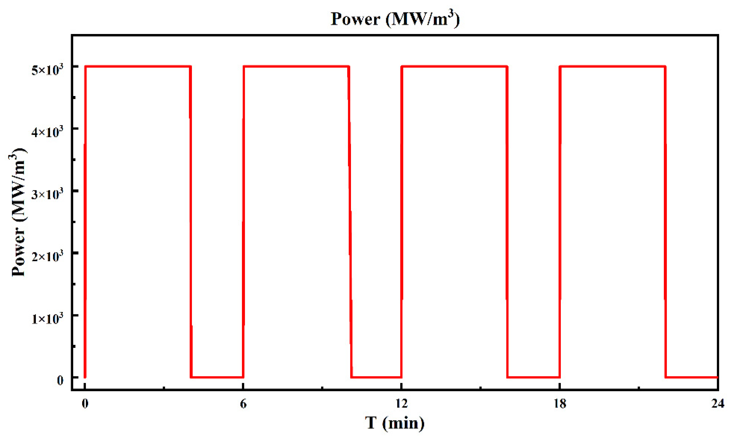
2.2. Power Cycling Reliability Modelling
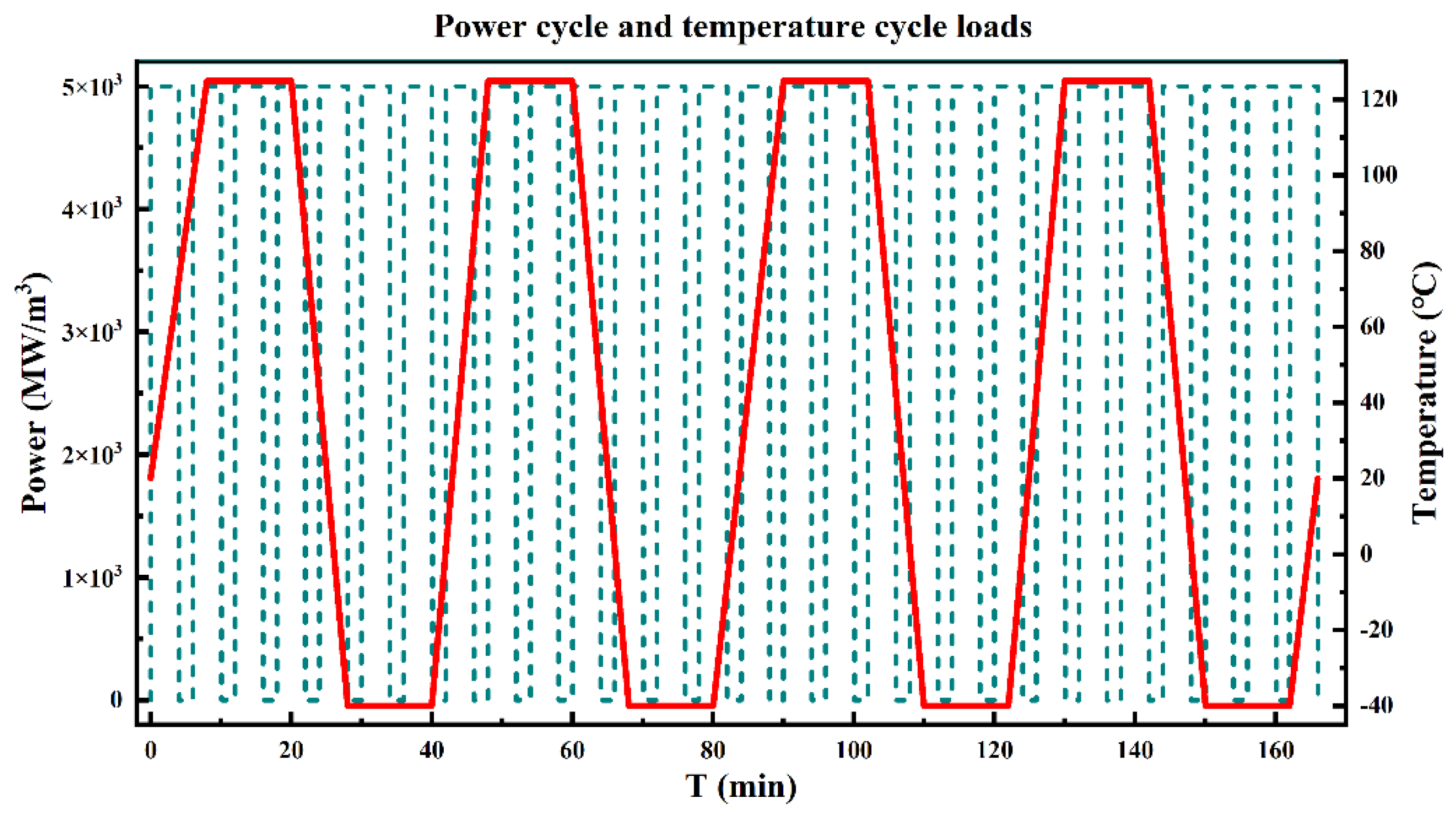
2.3. Electro-Thermal Coupling Complex Reliability Modelling
3. Results and Discussion
3.1. DC Reliability Analysis
3.2. Power Cycling Reliability Analysis
3.3. Electro-Thermal Coupling Complex Reliability Analysis
4. Conclusions
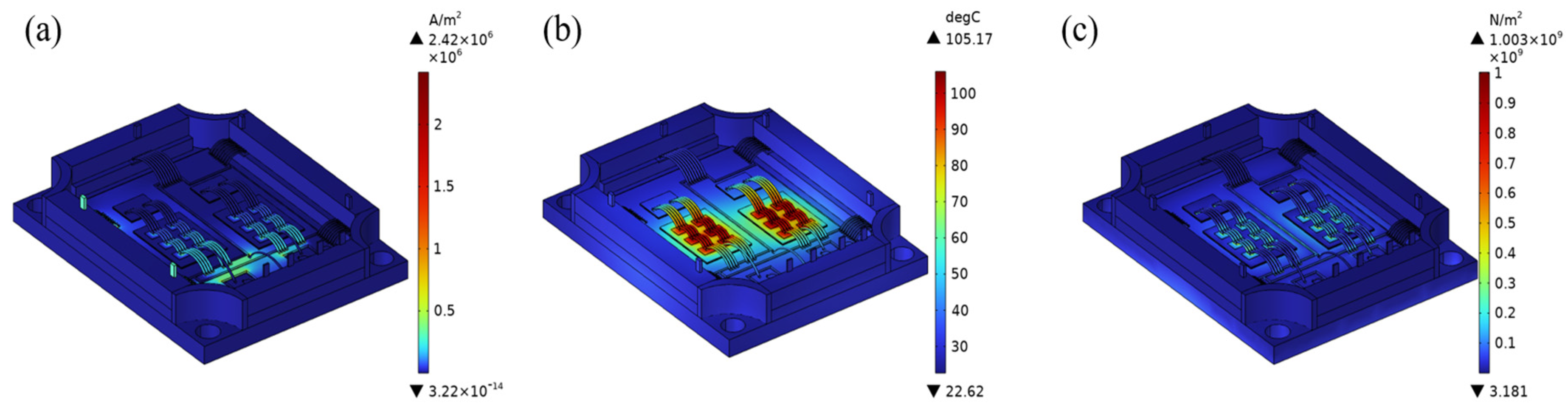
- The thermal reliability of the silver sintered material is particularly impressive, as the application of the solder material significantly reduces the DC operating junction temperature of the IGBT module to only 90.2 °C. This temperature represents a significant advantage of almost 15 °C compared to the IGBT module using SAC305 solder. This advantage not only improves the module’s thermal management efficiency but also significantly increases its long-term stability and reliability. Lower junction temperatures help to extend the life of the device and reduce the risk of potential failure due to overheating, thus improving the reliability performance of IGBT modules in real-world applications.
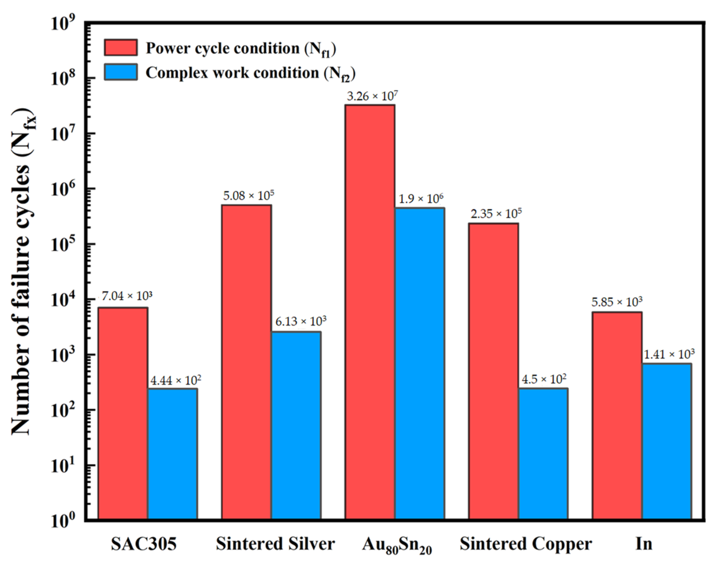
- In the studies conducted for power cycle reliability testing, significant differences in the fatigue life of different solder materials were observed. Specifically, the Au80Sn20 alloy solder showed superior fatigue performance with a fatigue life of up to 3.26 × 10⁷ cycles. This value not only reflects the stability and durability of the material under long-term cyclic loading, but also indicates its potential for application in high-temperature, high-stress environments. In contrast, the fatigue life of indium solder is shorter at 5.85 × 10³ cycles, a difference of almost four orders of magnitude, highlighting the significant impact of metallic solder on fatigue behavior.
- In the complex electro-thermal coupling environment, the Au80Sn20 solder also shows the best fatigue life of 1.9 × 10⁶ cycles, indicating its good adaptability and reliability under extreme working conditions. On the contrary, SAC305 solder shows a fatigue life of only 4.44 × 10² cycles in this environment, demonstrating its disadvantage under high thermal loads. This finding emphasizes that when designing IGBT modules, the selection of solder materials needs to fully consider their thermal performance and reliability in different operating environments to ensure the long-term stable operation of the products.
Author Contributions
Funding
Data Availability Statement
Conflicts of Interest
References
- Yang, Y.J. Research on Dynamic Simulation and Adaptive Design of Space Computer. Ph.D. Thesis, Xidian University, Xi’an, China, 2009. [Google Scholar]
- Zhang, K.; Liu, Y.; Kwok, H.-S.; Liu, Z. Investigation of electrical properties and reliability of GaN-based micro-LEDs. Nanomaterials 2020, 10, 689. [Google Scholar] [CrossRef] [PubMed]
- Coffin, L.F., Jr. A study of the effects of cyclic thermal stresses on a ductile metal. Trans. Am. Soc. Mech. Eng. 1954, 76, 931–949. [Google Scholar] [CrossRef]
- Manson, S.S. Behavior of Materials under Conditions of Thermal Stress; National Advisory Committee for Aeronautics: Washington, DC, USA, 1953; Volume 2933.
- Engelmaier, W. Fatigue life of leadless chip carrier solder joints during power cycling. IEEE Trans. Compon. Hybrids Manuf. Technol. 1983, 6, 232–237. [Google Scholar] [CrossRef]
- Solomon, H.D. The influence of hold time and fatigue cycle wave shape on the-low cycle fatigue of 60/40 solder. In Proceedings of the 38th Electronics Components Conference, Los Angeles, CA, USA, 9–11 May 1988; Proceedings. pp. 7–12. [Google Scholar]
- Yang, H. Influencing factors of fatigue life of nano-silver paste in chip interconnection. J. Electron. Mater. 2021, 50, 224–232. [Google Scholar] [CrossRef]
- Yang, K.; Zhou, L.; Wu, F.; Zhang, Y.; Han, Y.; Zhang, Z.; Wan, Y.; Huang, X.; Huang, D. Evaluation of Fatigue Crack Growth in Solder Layer of IGBT Module under Power Cycle by Using J-integral Method. In Proceedings of the 2021 22nd International Conference on Electronic Packaging Technology (ICEPT), Xiamen, China, 14–17 September 2021; pp. 1–6. [Google Scholar]
- Wakamoto, K.; Namazu, T. Mechanical Characterization of Sintered Silver Materials for Power Device Packaging: A Review. Energies 2024, 17, 4105. [Google Scholar] [CrossRef]
- Zhang, G.; Feng, S.; Zhou, Z.; Liu, J.; Li, J.; Zhu, H. Thermal fatigue characteristics of die attach materials for packaged high-brightness LEDs. IEEE Trans. Compon. Packag. Manuf. Technol. 2012, 2, 1346–1350. [Google Scholar] [CrossRef]
- Wang, Y.; Xu, D.; Yan, H.; Li, C.-F.; Chen, C.; Li, W. Low-temperature Copper Sinter-joining Technology for Power Electronics Packaging: A Review. J. Mater. Process. Technol. 2024, 332, 118526. [Google Scholar] [CrossRef]
- Ni, Y.; Chen, D.Y.; Cai, M.; Yang, D.G. Thermal mechanical analysis and fatigue life prediction of nano silver sintered layer encapsulated in SiC chip. Electron. Compon. Mater. 2024, 43, 238–245. [Google Scholar]
- Chen, W.; Yan, X.; Ibrahim, M.S.; Meda, A.H.; Fan, X.; Zhang, G.; Fan, J. Thermal-mechanical-electrical Co-design of Fan-Out Panel-Level SiC MOSFET Packaging with a Multi-objective Optimization Algorithm. In Proceedings of the 2023 IEEE 73rd Electronic Components and Technology Conference (ECTC), Orlando, FL, USA, 30 May–2 June 2023; pp. 2007–2011. [Google Scholar]
- Huang, X.; Wang, Y.; Zhu, Q.; Du, Z.; Zhou, L.; Liu, H. Thermal creep and fatigue failure of the sintered silver solder in a SiC-IGBT module under power cycling. Eng. Fail. Anal. 2023, 154, 107625. [Google Scholar] [CrossRef]
- Zhang, G.S. Study on Mechanical Properties of 80Au/20Sn Filler Metal Alloy. Ph.D. Thesis, Tianjin University, Tianjin, China, 2010. [Google Scholar]
- Long, H.Y. Electrothermally-Force-Multiple Physical Field Modeling and Failure Analysis of IGBT Devices Packaged by Nano Silver Sintering and Pressing. M.S. Thesis, Chongqing University, Chongqing, China, 2020. [Google Scholar]
- Wu, R.; McCluskey, F.P. Reliability of indium solder for cold temperature packaging. In Proceedings of the ASME InterPACK Conference, Vancouver, BC, Canada, 8–12 July 2007; pp. 553–556. [Google Scholar]
- Calabretta, M.; Sitta, A.; Oliveri, S.M.; Sequenzia, G. Power semiconductor devices and packages: Solder mechanical characterization and lifetime prediction. IEEE Access 2021, 9, 22859–22867. [Google Scholar] [CrossRef]
- Long, X.; Liu, Y.; Jia, F.; Wu, Y.; Fu, Y.; Zhou, C. Thermal fatigue life of Sn–3.0 Ag–0.5 Cu solder joint under temperature cycling coupled with electric current. J. Mater. Sci. Mater. Electron. 2019, 30, 7654–7664. [Google Scholar] [CrossRef]
- Smet, V.; Forest, F.; Huselstein, J.-J.; Richardeau, F.; Khatir, Z.; Lefebvre, S.; Berkani, M. Ageing and failure modes of IGBT modules in high-temperature power cycling. IEEE Trans. Ind. Electron. 2011, 58, 4931–4941. [Google Scholar] [CrossRef]
- Tang, Y.; Wang, B.; Chen, M.; Liu, B.L. Reliability and online evaluation of IGBTs at high temperatures. Trans. China Electrotech. Soc. 2014, 29, 17–23. [Google Scholar]
- Deng, E.P.; Chen, J.; Zhao, Y.S.; Zhao, Z.B.; Huang, Y.Z. Development of 90kW/3000A high voltage and high power IGBT device power cycle test equipment. Semicond. Technol. 2019, 44, 223–231. [Google Scholar]
- Li, Y.P.; Zhou, L.W.; Sun, P.J. Summary of accelerated aging methods for IGBT power modules. J. Power Supplies 2016, 14, 122–135. [Google Scholar]
- Hensler, A.; Lutz, J.; Thoben, M.; Zachariae, J. Power cycling tests at high temperatures with IGBT power modules for hybrid electrical vehicle applications. In Proceedings of the 3rd Electronics System Integration Technology Conference ESTC, Berlin, Germany, 13–16 September 2010; pp. 1–6. [Google Scholar]
- Huang, H.; Mawby, P.A. A lifetime estimation technique for voltage source inverters. IEEE Trans. Power Electron. 2012, 28, 4113–4119. [Google Scholar] [CrossRef]
- Smet, V.; Forest, F.; Huselstein, J.-J.; Rashed, A.; Richardeau, F. Evaluation of Vce Monitoring as a Real-Time Method to Estimate Aging of Bond Wire-IGBT Modules Stressed by Power Cycling. IEEE Trans. Ind. Electron. 2012, 60, 2760–2770. [Google Scholar] [CrossRef]
- Guo, Y.Q.; Gao, T.; Xu, Y.J.; Liang, L.H.; Liu, Y. Life prediction of power module lead bond interface temperature cycle. J. Mech. Electr. Eng. 2018, 35, 73–78. [Google Scholar]
- Ji, B.; Song, X.; Cao, W.; Pickert, V.; Hu, Y.; Mackersie, J.W.; Pierce, G. In situ diagnostics and prognostics of solder fatigue in IGBT modules for electric vehicle drives. IEEE Trans. Power Electron. 2014, 30, 1535–1543. [Google Scholar]
- Ciappa, M. Selected failure mechanisms of modern power modules. Microelectron. Reliab. 2002, 42, 653–667. [Google Scholar] [CrossRef]
- Huang, Y.; Luo, Y.; Xiao, F.; Liu, B. Failure mechanism of die-attach solder joints in IGBT modules under pulse high-current power cycling. IEEE J. Emerg. Sel. Top. Power Electron. 2018, 7, 99–107. [Google Scholar] [CrossRef]
- Peng, B.; Zhang, P.; Chen, T.Q.; Zhao, R.C.; Wu, Z.H.; Liu, H. Reliability study of interconnect interface for high-power semiconductor lasers. Infrared Laser Eng. 2018, 47, 109–116. [Google Scholar]


| Structure | Length/mm | Width/mm | Height/mm |
|---|---|---|---|
| IGBT Chip | 9 | 12 | 0.15 |
| FRD Chip | 6 | 5 | 0.15 |
| FRD Chip Solder Layer | 6 | 5 | 0.12 |
| IGBT Chip Solder Layer | 9 | 12 | 0.12 |
| DBC Copper Layer | 25 | 35 | 0.3 |
| DBC Ceramic Layer | 26 | 36 | 0.38 |
| DBC Solder Layer | 25 | 35 | 0.12 |
| Substrate | 28 | 38 | 3 |
| Material | Electric Conductivity [S/m] | Relative Dielectric Constant [1] | Thermal Conductivity [W/(m·K)] | Density [kg/m3] | CTE [10−6/K] | Poisson’s Ratio [1] | Young’s Modulus [GPa] | Heat Capacity [J/(kg·K)] |
|---|---|---|---|---|---|---|---|---|
| Al | 3.8 × 10⁷ | 1 | 238 | 2700 | 23 | 0.33 | 70 | 900 |
| Si-IGBT | 3.0 × 10⁻⁴ | 11.7 | 130 | 2329 | 2.6 | 0.28 | 170 | 700 |
| Si-FRD | 1.0 × 10⁻¹² | 11.7 | 130 | 2329 | 2.6 | 0.28 | 170 | 700 |
| Cu | 6.0 × 10⁷ | 1 | 400 | 8960 | 17 | 0.35 | 110 | 385 |
| AlN | 8.0 × 10⁻¹⁶ | 9 | 200 | 3320 | 4.2 | 0.2 | 309 | 780 |
| OFE-Cu | 5.8 × 10⁷ | 1 | 390 | 8960 | 16.5 | 0.34 | 130 | 390 |
| PPS | 1.0 × 10⁻⁹ | 1 | 1.5 | 1700 | 7 | 0.36 | 1.5 | 1300 |
| SAC305 | 9.1 × 10⁶ | 4.5 | 50 | 7440 | 23 | 0.3 | 40 | 230 |
| Sintered Silver | 4.9 × 10⁷ | 6.9 | 240 | 10,000 | 19 | 0.38 | See Table 2 | 235 |
| Au80Sn20 | 1.6 × 10⁹ | 6 | 57 | 8500 | 16 | 0.4 | 68 | 2400 |
| Sintered Copper | 4.5 × 10⁷ | 1 | 125 | 7500 | 16.74 | 0.345 | 11.7 | 385 |
| In | 1.2 × 10⁷ | 10 | 81.6 | 7290 | 32.1 | 0.45 | 11 | 233 |
| Temperature (°C) | −50 | 0 | 25 | 60 | 120 | 150 |
|---|---|---|---|---|---|---|
| Young’s Modulus [GPa] | 9 | 8 | 6.25 | 4.5 | 2.65 | 1.6 |
| Symbol | SAC305 | Sintered Silver | Au80Sn20 | Sintered Copper | In |
|---|---|---|---|---|---|
| A [1/s] | 4.1 × 10⁶ | 9.81 | 93.07 | 2.677 | 1.5 × 10⁷ |
| Q [J/mol] | 78,151.6 | 47,442 | 63,009 | 59,407 | 90,046 |
| ξ [1] | 1.5 | 12 | 11 | 12 | 11 |
| m [1] | 0.303 | 0.6572 | 0.573 | 0.88 | 0.303 |
| Ssat [N/m2] | 1.4 × 10⁷ | 1.0 × 10⁸ | 4.7 × 10⁸ | 5.4 × 10⁷ | 5.6 × 10⁷ |
| S0 [N/m2] | 1.2 × 10⁷ | 2.9 × 10⁶ | 7.0 × 10⁷ | 4.5 × 10⁵ | 8.0 × 10⁷ |
| h0 [N/m2] | 1.4 × 10⁹ | 1.5 × 10¹⁰ | 3.1 × 10¹¹ | 2.1 × 10⁸ | 2.6 × 10³ |
| a [1] | 1.3 | 1 | 1.402 | 1 | 1.34 |
| n [1] | 0.07 | 0.00326 | 0.046 | 2.9 × 10⁻⁸ | 0.0231 |
| Coffin-Manson Model Parameters | SAC305 | Sintered Silver | Au80Sn20 | Sintered Copper | In |
|---|---|---|---|---|---|
| Fatigue ductility coefficient (ε′f) | 0.24 | 0.325 | 10.114 | 0.203 | 9.744 |
| Fatigue ductility index (c) | −0.407 | −0.455 | −0.612 | −0.315 | −0.802 |
Disclaimer/Publisher’s Note: The statements, opinions and data contained in all publications are solely those of the individual author(s) and contributor(s) and not of MDPI and/or the editor(s). MDPI and/or the editor(s) disclaim responsibility for any injury to people or property resulting from any ideas, methods, instructions or products referred to in the content. |
© 2024 by the authors. Licensee MDPI, Basel, Switzerland. This article is an open access article distributed under the terms and conditions of the Creative Commons Attribution (CC BY) license (https://creativecommons.org/licenses/by/4.0/).
Share and Cite
Ma, H.; Gou, M.; Tian, X.; Tan, W.; Liang, H. Reliability Simulation of IGBT Module with Different Solders Based on the Finite Element Method. Metals 2024, 14, 1141. https://doi.org/10.3390/met14101141
Ma H, Gou M, Tian X, Tan W, Liang H. Reliability Simulation of IGBT Module with Different Solders Based on the Finite Element Method. Metals. 2024; 14(10):1141. https://doi.org/10.3390/met14101141
Chicago/Turabian StyleMa, Haoran, Min Gou, Xingjian Tian, Wei Tan, and Hongwei Liang. 2024. "Reliability Simulation of IGBT Module with Different Solders Based on the Finite Element Method" Metals 14, no. 10: 1141. https://doi.org/10.3390/met14101141
APA StyleMa, H., Gou, M., Tian, X., Tan, W., & Liang, H. (2024). Reliability Simulation of IGBT Module with Different Solders Based on the Finite Element Method. Metals, 14(10), 1141. https://doi.org/10.3390/met14101141