Article

Biocoke Thermochemical Properties for Foamy Slag Formations in Electric Arc Furnace Steelmaking

1
K1-MET GmbH, 8700 Leoben, Austria
2
Chair of Ferrous Metallurgy, Montanuniversitaet Leoben, 8700 Leoben, Austria
3
Department of Chemistry, Dnіpro Unіversіty of Technology, 49005 Dnipro, Ukraine
4
G.V. Kurdyumov Institute for Metal Physics of the National Academy of Sciences of Ukraine, 02000 Kyiv, Ukraine
*
Author to whom correspondence should be addressed.
Metals 2024, 14(1), 13; https://doi.org/10.3390/met14010013
Submission received: 21 November 2023 / Revised: 16 December 2023 / Accepted: 19 December 2023 / Published: 21 December 2023
(This article belongs to the Special Issue Electric Arc Furnace and Converter Steelmaking)

Abstract

:
This paper is devoted to studying the thermochemical properties of carbon sources (laboratory-scale conventional coke, biocoke with 5 wt.%, and 10 wt.% wood pellet additions) and the influence of these properties on foamy slag formations at 1600 °C. Thermogravimetric analysis (TGA) conducted under air unveiled differences in mass loss among carbon sources, showing an increasing order of coke < biocoke with 5 wt.% wood pellets < biocoke with 10 wt.% wood pellets. The Coats–Redfern method was used to calculate and reveal distinct activation energies among these carbon sources. Slag foaming tests performed using biocoke samples resulted in stable foam formation, indicating the potential for biocoke as a carbon source to replace those conventionally used for this process. Slag foaming characters for biocoke with 5 wt.% wood pellets were improved more than coke. Using biocoke with 10 wt.% wood pellets was marginally worse than coke. On the one hand, for biocoke with 5 wt.% wood pellets, due to increased reactivity, the foaming time was reduced, but it was sufficient and optimal for slag foaming. Conversely, biocoke with 10 wt.% wood pellets reduced foaming time, proving insufficient and limiting the continuity of the foaming. This study highlights that thermochemical properties play a significant role, but comprehensive assessment should consider multiple parameters when evaluating the suitability of unconventional carbon sources for slag foaming applications.

1. Introduction

As it is imperative to reduce carbon emissions and environmental impact, there is a growing focus on exploring novel strategies to improve the efficiency and ecological viability of the electric arc furnace (EAF) steelmaking process [1]. Slag foaming, an important process of EAF steelmaking, hinges on injecting oxygen and carbon sources into the molten metal bath and slag layer, respectively. This dual-injection approach serves the dual purpose of oxidizing impurities while fostering the formation of a stable and effective foamy slag [2]. Precisely, the carbon source reacts with the FeO, producing CO, which primarily produces foaming. The chemical reactions [3] generate CO/CO2 gases, forming bubbles within the slag, thereby creating foam. Foamy slags serve to increase surface areas, facilitating multi-phase reactions. This enhances reaction kinetics, heat transfer, and energy efficiency while reducing electrode consumption [4,5,6,7]. Conventional carbon sources (anthracite, metallurgical coke, calcined petroleum coke, and graphite) applied are hardly dispensable in this process [8]. One such solution gaining prominence is the incorporation of biocoke [9] as a carbon source, offering a pragmatic and realistic approach to address the challenges of both performance and the environment. Biocoke can be used in slag foaming where the tolerance for reactivity and strength is not strict [10,11,12]. In addition to reactivity and strength, the thermochemical properties of carbon materials are important factors to consider when studying the possibility of using these materials for metallurgical processes [13,14,15]. This is especially important when the goal is to replace traditional ones with auxiliary sources, as it can determine the applicability and suitability of a particular process.
Thermogravimetric analysis (TGA) is a tool employed to investigate the thermal decomposition and combustion of materials, and it has found significant utility in the study of carbon material combustion processes [16]. Coke combustion is a complex process involving various chemical and physical processes. This includes the release of volatile matters, the ignition and continuous burning of fixed carbon, and the creation of ash residues. Each stage has its specific kinetics, which TGA can precisely investigate. TGA affords a precise means for quantifying mass variations as a function of temperature elevation, thereby yielding crucial insights into the quantification of weight loss attributed to the evolution of volatiles and the identification of the temperature thresholds for ignition and combustion. Furthermore, TGA enables the examination of reaction kinetics, facilitating the elucidation of reaction mechanisms and the evaluation of kinetic parameters.
Indeed, the non-isothermal TGA method to study the coke combustion characteristics in a pure oxygen atmosphere has been used by Yang et al. [17]. It was concluded that the change in activation energy Ea strongly depends on the conversion rate, reflecting the combustion process’s complexity. Moreover, combustion characteristics and kinetics of high- and low-reactivity metallurgical cokes under air atmosphere were investigated by Qin et al. [18]. In this research, the coke combustion Ea was calculated using the Coats–Redfern method, as well as the Flynn–Wall–Ozawa (FWO) and Vyazovkin methods. The general tendency was that low-reactivity coke’s Ea was more than that of high-reactivity coke. Additionally, the ignition and burnout temperatures were increased for low-reactivity coke, and the thermal stability of low-reactivity coke was improved compared to high-reactivity coke.
It is worth noting that practically no such studies have been carried out for biocoke. Although, considering the interest in using biomass or biochar, the thermochemical properties of these materials have been investigated to evaluate their applicability for EAF steelmaking. Fidalgo et al. [19] studied the thermochemical properties and reactivities of biochar derived from grape and pumpkin seeds to assess their suitability in EAF steelmaking. It was found that TGA analyses have revealed that grape seed char presents higher gasification and combustion reactivities and slower release of volatiles in comparison to the other samples, which may improve supply heat and sustain reactions.
In turn, Cardarelli et al. [20] studied the thermal effects of the combustion of pretreated biomasses via pyrolysis, torrefaction, and hydrothermal carbonization compared to anthracite coal, which were modeled for EAF application. The impact of the combustion reaction on the temperature distribution inside the EAF and the influence of intermediate gas release was analyzed. The results showed that using biochar instead of fossil coal in the EAF steelmaking process did not involve significant negative differences.
Specifying thermochemical parameters (thresholds of ignition temperature and burnout temperature; mass loss) can be of interest to substantiate the effect of carbon sources on foaming behavior, among other well-studied properties such as ash content and composition, volatile matters, fixed carbon, and microstructural features of carbon sources. Many researchers have investigated different slag foaming and carbon/slag interactions during this process [21]. However, since this process is a complex and unstable phenomenon, many factors can usually influence optimal achievement in slag foaming [22]. In studying slag foaming as a function of different carbon sources, in this case, it is quite challenging to compare the results obtained since the properties of one type of carbon material may differ, taking into account even equal test conditions.
However, some major tendencies should be mentioned:
The value of fixed carbon, ash value, and composition are important in carbon source interactions with molten slag and slag foaming behavior [23].
The value of volatile matters can also contribute to slag foaming behavior, but it is less effective than the gas from the chemical reaction [24].
Carbon microstructure is an important factor worth considering [8].
Wetting capacity, surface roughness, and chemical reactivity of carbon sources are important parameters influencing this process [8].
Among the array of carbon sources employed for slag foaming, biocoke could be considered an adequate candidate since, on the one hand, it allows for the reduction in coal consumption necessary to produce biocoke by replacing it with biomass/biochar; in addition, on the other hand, it is a source of carbon that complies with the required reactions [25] for foaming slag formation. Slag foaming is quite a complex and dynamic process affected by the following factors: type of carbon sources and their properties, composition of slag and its properties, test conditions, carbon/slag interfacial reaction kinetics, gas generation, etc.
Thus, this study focuses on thermogravimetric evaluation to examine the combustion characteristics and kinetics of coke and two biocoke samples. These thermochemical characteristics are expected to explain the influence of carbon sources during the foaming process and provide information for the slag foaming operation. The research undertaken is oriented toward defending the consequential impact of unconventional carbon sources on slag foaming formation within the confines of controlled experimental settings in each test.

2. Materials and Methods

The slag was obtained from powders characterized by specific chemical compositions, including iron (II) oxide, denoted as FeO; calcium oxide, denoted as CaO (≥96%); silica, denoted as SiO2 (≥99%); magnesium oxide, denoted as MgO (≥98%); and aluminum oxide, denoted as Al2O3 (≥99%). The precise compositions are provided in Table 1. The oxide components and the target compositions are based on the primary chemical compounds in EAF slags [26]. This composition aims to induce slag foaming.
For the production of laboratory-scale coke or biocoke specimens, 2 kg of a coal blend (for coke production) or a mixture of 95 wt.% coal and 5 wt.% wood pellets (for the biocoke production, referred to as BC5) or a mixture comprising 90 wt.% coal and 10 wt.% wood pellets (for the production of biocoke, referred to as BC10) were prepared. Afterward, a retort was introduced into a preheated electric shaft-type laboratory furnace, initially maintained at 850 °C. Following this initial preheating phase, the temperature was further elevated to 1000 °C and held for 75 min. The coking process occurred without oxygen access. During the coking process, volatile matters were ejected from the retort and combusted. Subsequently, the retort was withdrawn from the furnace, subjected to water cooling, and cooled under ambient air conditions until it reached room temperature.
The main characters of carbon sources are shown in Table 2. The proximate and elemental analysis for carbon sources were carried out according to ASTM D3172-13 [27]. Based on the obtained values for volatile matters and sulfur for the resulting coke and biocokes, they may not meet the requirements as fuel and reducing agents for blast furnace purposes [28]; however, if the fixed carbon content is also considered, coke and biocokes can be used, for example, for slag foaming in EAF steelmaking.
In preparation for the foaming experiments, all three carbon sources were subjected to particle size crushing to achieve a particle size range between 0.5 and 1.0 mm. The stoichiometric required amount of carbon source based on fixed carbon was calculated by considering the weight of the slag, the quantity of FeO within it, and the specific amount of fixed carbon needed for the FeO + C = Fe + CO reduction reaction and is presented in Table 3.
The slag foaming was conducted using an induction high-temperature furnace, the MU-900 (manufactured by Indutherm Erwärmungsanlagen GmbH, Walzbachtal, Germany), and involved the use of three carbon sources: conventional laboratory-scale coke (utilized as a reference), BC5, and BC10. Prior to initiating the slag foaming experiments, a quantity of approximately 5 g of ultra-low carbon (ULC) steel, characterized by a carbon content of 0.007 wt.%, was positioned at the base of an alumina crucible. This crucible featured inner dimensions measuring 63 mm in diameter, a wall thickness of 4 mm, and a height of 99 mm. Subsequently, roughly 101 g of slag powder was introduced into the crucible, and the filled alumina crucible was placed within a larger graphite crucible featuring inner dimensions of 70.3 mm in diameter, a wall thickness of 20 mm, and a height of 202 mm. The temperature was elevated to 1600 °C and held for 1 h to ensure complete melting. Following the foaming tests, liquid nitrogen was employed to rapidly cool and solidify the foam structure, after which it was allowed to naturally cool to ambient temperature [29,30,31]. A video was recorded throughout the experiments to reveal the slag foam formation for each carbon source applied.
To measure the height of the slag foam, the difference between the top surface of the foam and the unfoamed layer at the bottom of the crucible was calculated. This measurement was conducted at three different positions within the crucible, and the average of these values provided the mean height of the slag foam.
Based on the slag foam height, the volume of slag before (Vslag) and after foaming (Vfoam) was calculated using Equations (1) and (2):
V s l a g = d 2 · π 4 · h s l a g ,
V f o a m = d 2 · π 4 · h f o a m ,
where d is the inner diameter of the crucible, cm; hslag is slag height before foaming, cm; hfoam is slag height after foaming, cm.
The relative slag foaming volume ( Δ V V 0 ) was calculated by Equation (3):
Δ V V 0 = V f o a m V s l a g V s l a g ,
Thermogravimetric analysis (TGA)/differential thermogravimetry (DTG) was carried out by SDT Q600 V20.9 Build 20 (TA Instruments, New Castle, DE, USA) to analyze the air combustion process of carbon sources. The carbon source samples (30.0 ± 1.0 mg) were loaded into an alumina pan (Al2O3), and the air flow rate was set to 100.0 mL·min−1 during test runs. In this experiment, the temperature was raised to 1100.0 °C from room temperature, with a heating rate of 5 °C/min under the air. The same experimental conditions were used for all of the tests with carbon sources. The change in the mass of the samples during heating was recorded to obtain the TG-DTG curves using the software OriginPro 2023b (version 10.0.5.157). The baseline for mass loss was obtained using an empty alumina pan.
The ignition and burnout temperatures of the samples were determined via the intersection method, according to [32]. The Coats–Redfern method was used to estimate the activation energy (Ea) on the combustion zone between the ignition and the burnout temperature [18,33,34].
FTIR spectroscopy analysis used an attenuated total reflectance (ATR) accessory with an Agilent Cary 630 FTIR spectrometer manufactured by Agilent Technologies, Santa Clara, CA, USA. For each sample, 32 scans were performed within the wavenumber range of 4000–650 cm−1, employing a spectral resolution of 2 cm−1 and achieving a high wavenumber accuracy of 0.05 cm−1. The software used for peaks analysis of the obtained spectra was OriginPro 2023b (version 10.0.5.157).
Afterward, using Bragg’s Law, the aromatic planes of carbon crystallites (d002) and the carbon crystallite width (La) were calculated according to [35,36] using OriginPro 2023b (version 10.0.5.157) based on X-ray diffraction (XRD) spectra of carbon source samples that were obtained using a Bruker AXS D8 advance diffractometer (Bruker Corporation, Billerica, MA, USA) with a lynxeye detector and a Cu X-ray tube with Cu Kα radiation.

3. Results and Discussion

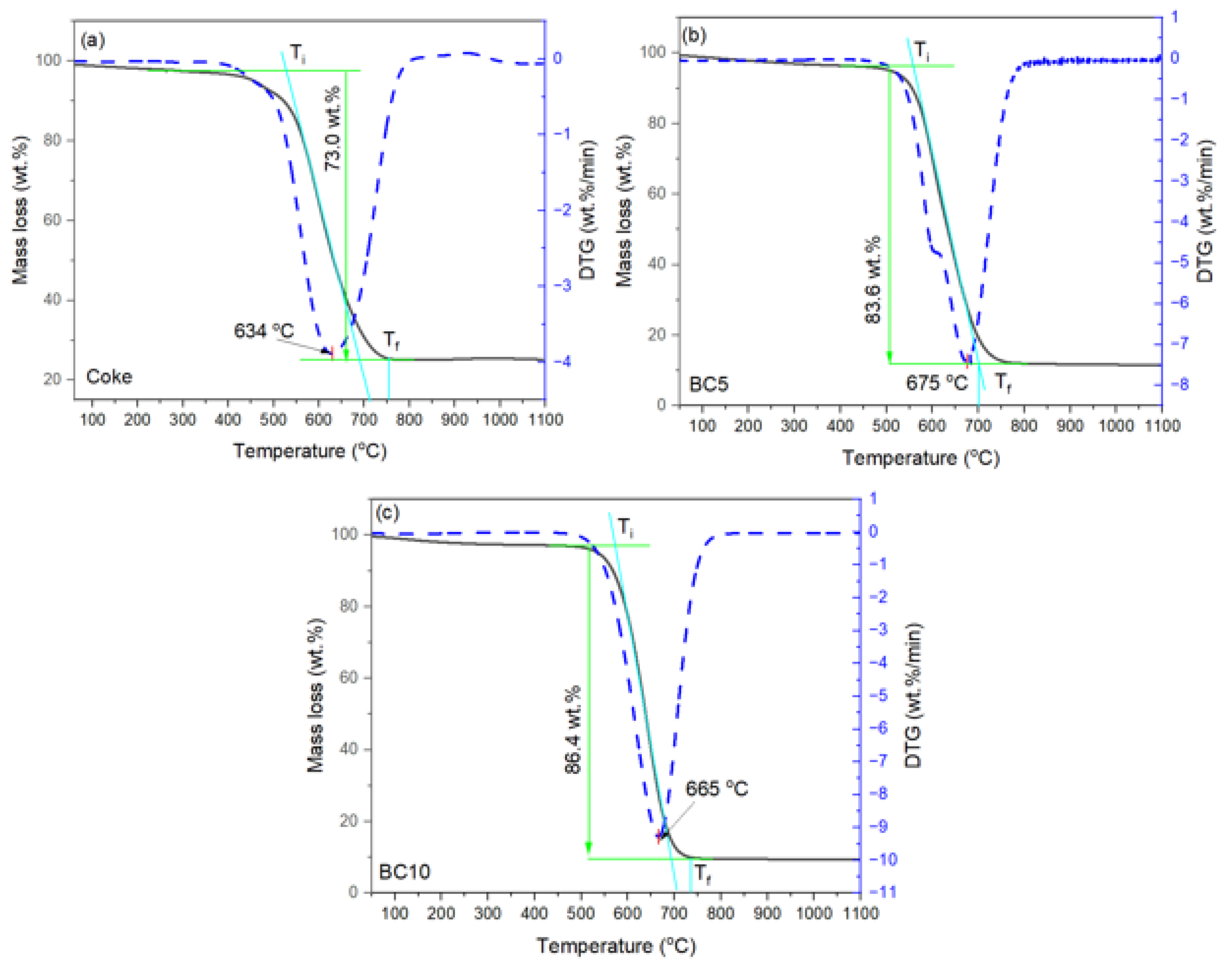
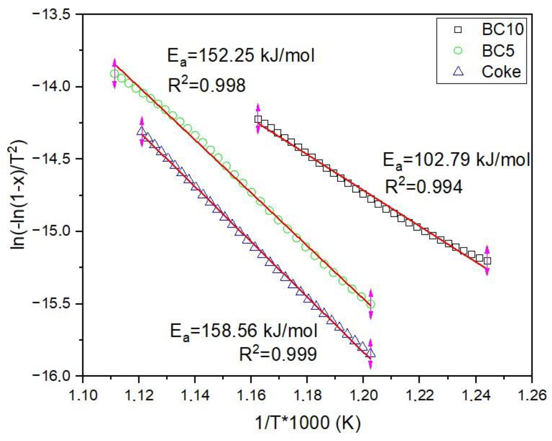
3.1. Thermogravimetric Characters of Carbon Sources

The reactivity of the carbon source samples can be studied via the TGA, and the results for the determination of mass change rates due to combustion under air are reported. The weight of the samples were recorded using the TGA technique, and the TG–DTG curves were obtained for the coke and biocoke samples. According to the DTG profiles (Figure 1a–c), the three carbon source samples show curves with a single definite peak rate; so, in this case, the combustion should be divided, generally, into three stages: (1) start of combustion and mass loss of coke/biocoke samples. (2) The second stage is a reaction with air oxygen. The coke/biocoke sample loses weight due to the combustion of fixed carbon, and the reaction rate is determined by the structural features of the carbon source. (3) In the final stage, after burning, the combustible components in coke/biocoke continue to decompose at a very low rate, producing ash as the final residue. The curves show a plateau for all three samples in the region of 750 °C and higher.
Notably, for all three samples, the initial stage of gradual weight loss due to moisture removal up to 100 °C and adsorbed gases up to 250 °C is practically unnoticeable. This is typically the case with coal or biomass/biochar; however, since coke or biocoke is a more heat-treated carbon material, this stage is not noticeable from the curves, considering low moisture and volatile matters, although it is evident from the proximate analysis in Table 2.
Regarding the mass loss curve, the main stage spans the region where the release and combustion of fixed carbon are responsible for the mass loss of coke and biocoke samples. Coke is characterized by the lowest weight loss and reaches 73.0 wt.% at 634 °C. The weight loss observed in biocoke samples is significant. When comparing the biocoke samples, the sample containing 5 wt.% wood pellets shows a slightly lower weight loss of 83.6 wt.% at 675 °C, whereas the biocoke sample with 10 wt.% wood pellets exhibits a higher weight loss of 86.4 wt.% at 665 °C.
A distinctive phenomenon is the significant difference in mass loss between the coke and the two biocoke samples. Additionally, there is a less noticeable difference in weight loss between biocoke samples. Considering the ash content for coke of 11.1 wt.%–db (Table 2), it can be concluded that this carbon source did not burnout completely during the TGA process. It can be explained by the fact that in the pan, the ash particles covering the surface of the carbon source particles block the pores present on the surface of the coke sample, increasing the extent of diffusion resistance realized. This significantly influences combustion reactivity and the degree of burnout. This observation was also noticed in [17]. In addition, since the coke did not burn out completely, this also explains the low peak temperature (Tp) compared to biocokes.
Moreover, the combustion characteristic indexes of the coke/biocoke can be obtained through the calculation and analysis of TG and DTG curves, which are mainly represented by ignition temperature (Ti) and peak temperature (Tp), which reveal the temperature of maximum mass loss, burnout temperature (Tf), and T, which represents the difference between ignition temperature and burnout temperature [18]. The combustion characteristics of carbon source samples, the temperatures of coke, and two biocoke samples are shown in Table 4.
Higher burnout temperatures Tf are explained by the presence of the most stable components in the carbon material. Generally, Ti and Tf temperatures would be low if the reactivity of the carbon sources were high. However, the values of Ti and Tf on the TG curves turned out to be uncertain. The ignition temperature does not differ much between biocokes. The maximum burnout temperature for coke is 758 °C. The ΔT value of 228 °C may indicate a stronger coke structure and lower reactivity than biocoke samples. The ΔT value indicates that the biocoke samples’ combustion duration was shorter than that of coke. However, the ignition temperature is lower for coke compared with the biocoke samples.
To explain this, it requires considering the microstructural aspects of the carbon sources. The interlayer spacing between aromatic planes of carbon crystallites (d002) was calculated, obtaining a value of 0.36 nm for coke and 0.35 nm for the biocoke samples. Typically, a more minor d002 indicates a more ordered carbon structure and a higher degree of graphitization [37]. In this case, the similar d002 value across coke and the two biocoke samples suggests a comparable level of structural order. This similarity can be attributed to the relatively small proportion of wood pellet additives, which did not significantly influence the microstructural characteristics of the biocoke. Additionally, when analyzing biocokes, the appropriate distribution of the main material of coke and wood pellet particles in the sample is important since the indicators depend on the distribution of pyrolyzed wood pellets in the test sample. The comparable values of d002 prevent us from making decisive assessments regarding the impact of microstructure on explaining combustion characteristics. On the other hand, the La index indicates that coke has slightly better microstructural properties [38,39] compared to biocokes.
If we focus on the correlation between combustion characters and the effect of carbon source properties (Table 2), the volatile matter and fixed carbon values do not significantly lead to conclusive observations as these values are closely aligned. However, a general criterion suggests that the carbon source burns at lower temperatures when it is more hydrogenated [40]. The reason behind the earlier start of coke ignition compared to biocoke samples might be attributed to the higher hydrogen content in coke (0.30 wt.%−db) in contrast to biocoke samples with 0.27 wt.%−db and 0.22 wt.%−db for biocoke with 5 wt.% wood pellets and biocoke with 10 wt.% wood pellets, respectively.
Assessing the mass loss kinetics during the combustion of coke or biocokes is challenging due to the complex aromatic substances and the influence of multiple factors. An Arrhenius-type kinetic model was used to analyze the TG-DTG data. Based on DTG curves for all three carbon samples at a constant heating rate (5 °C/min), a single peak was observed in the range from ignition temperature to burnout temperature. This indicates that the combustion process is a single-step process. The activation energy results for the three carbon source samples are shown in Figure 2. Ea reflects the minimum energy that the reactant molecules need to reach the activated state during a chemical reaction. The higher activation energy value for coke, at 158.56 kJ/mol, suggests that more energy is required to initiate the reaction for coke compared to other carbon sources.
The activation energy values differed among the samples. The biocoke with 5 wt.% wood pellets exhibited a slightly lower activation energy of 152.25 kJ/mol, implying a noticeable but not significantly influential impact due to the addition of wood pellets. The lowest activation energy value was recorded in the biocoke sample containing 10 wt.% wood pellets at 102.79 kJ/mol. This substantial decrease in activation energy is noteworthy compared to both coke and biocoke with 5 wt.% wood pellets.
Although the activation energy values for coke and biocoke with 5 wt.% wood pellets were close to the values specified in [18] for a heating rate of 5 °C/min calculated by the Coats–Redfern method, they were marginally lower. This difference can be attributed to the fact that the samples in this study were laboratory-based. Adding 10 wt.% wood pellets to produce biocoke significantly contributed to decreased activation energy.
An FTIR analysis was conducted to confirm the occurrence of incomplete burnout in the TGA combustion of coke. In Figure 3, FTIR spectroscopy peaks and their corresponding assignments for carbon materials are depicted after conducting TGA. The O=C=O stretching vibrations, characteristic of carbon dioxide (CO₂), were identified at distinct wavenumbers for the different carbon sources: 2361 cm−1 for coke, 2360 cm−1 for biocoke with 10 wt.% wood pellets, and 2354 cm−1 for biocoke with 5 wt.% wood pellets.
The presence of oxygen-containing groups [33] is specific to coke, which is indicated by a C–O stretching peak (related to primary alcohol) at 1054 cm−1 and 1042 cm−1 for biocoke with 5 wt.% wood pellets. Meanwhile, biocoke with 10 wt.% wood pellets features a peak at 1132 cm−1, signifying aliphatic ether functionality. Transmittance peaks at 900–700 cm−1 refer to the C–H bending vibrations of aromatic hydrocarbons, which sharply decrease for biocoke with 10 wt.% wood pellets, indicating the elimination of functional groups of aromatic compounds, resulting in a change in their relative –CH content. For biocoke with 10 wt.% wood pellets, the intensity of the peaks is very weak compared to coke or biocoke with 5 wt.% wood pellets, indicating that biocoke with 10 wt.% wood pellets has almost entirely reacted with air oxygen.

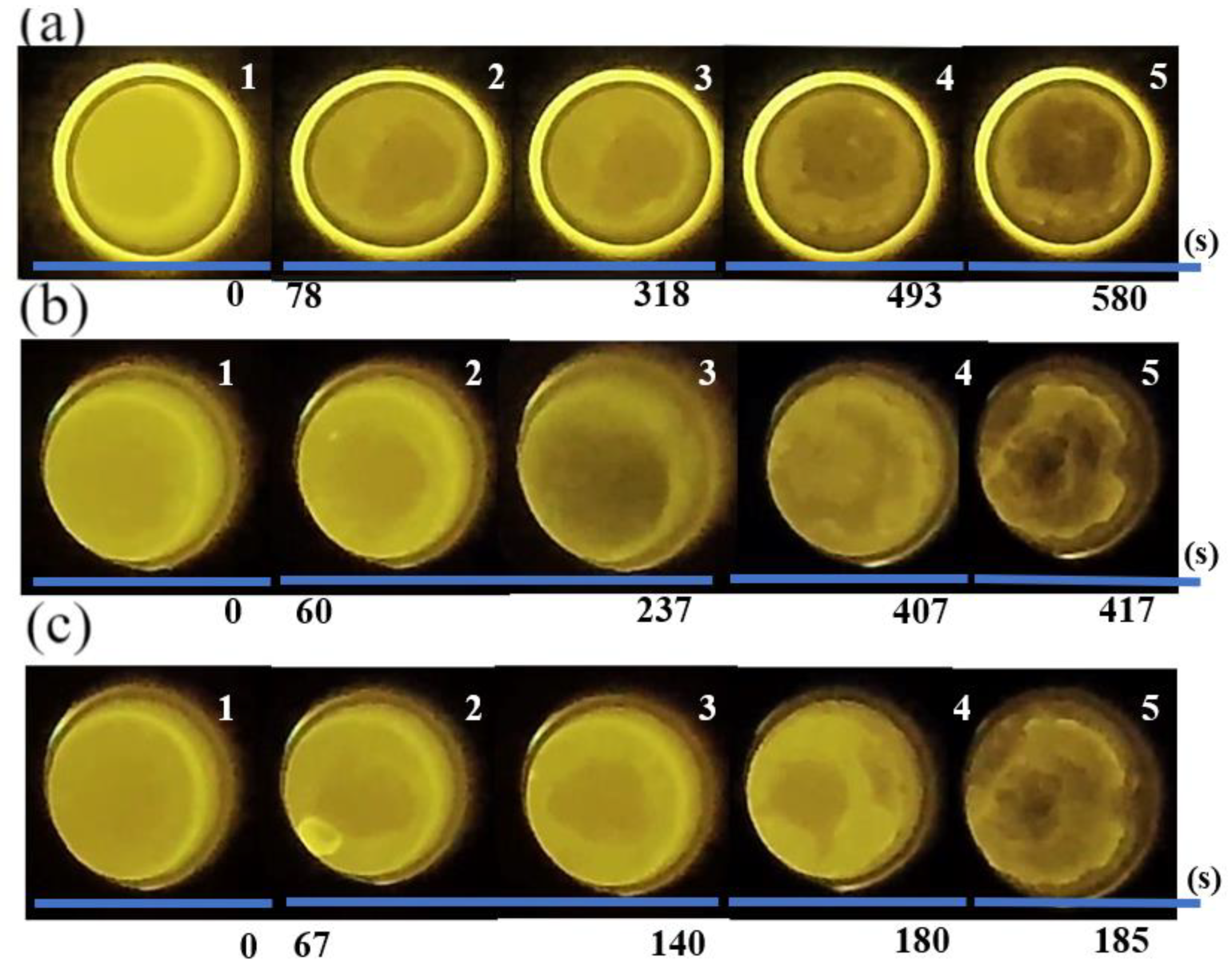
3.2. Formation of Slag Foam and Its Characteristics

It is worth recognizing that the specified test methodology of slag foaming has some peculiarity. Since the carbon material was supplied from above to the molten slag, taking into account the high temperature of 1600 °C, it was possible to observe the combustion process of some of the carbon source particles on the slag surface. With a more reactive carbon source, this process was generally more pronounced. Thus, when using coke, this was weakly noticed and more pronounced when using biocoke samples. Further, the carbon source particles floated on the molten slag surface, and slag foaming formations were initiated on the slag surface simultaneously. Because of this, quick mixing of the carbon source and molten slag was required each time. Nonetheless, slag foam formation is presented in Figure 4 for each carbon source applied. Slag foam formation is segmented to show this process from the initiation of foaming to its final stage. Notably, the duration of foaming varied among the three cases; however, the stages and evolution of slag foam exhibited minor differences. When coke was employed (Figure 4a), the foaming process showed the longest duration, extending to approximately 580 s. In contrast, the formation of equivalent stages during slag foaming with biocoke containing 5 wt.% wood pellets (Figure 4b) occurred over approximately 417 s. Subsequently, with biocoke incorporating 10 wt.% wood pellets, slag foaming was completed in about 185 s (Figure 4c). Segment 1 on Figure 4a–c depicts the initial state of the system before introducing the carbon source, representing the initial height of the molten slag in the crucible. The time gap between Segment 1 and Segment 2 is caused by the time of addition of the carbon source and the slight mixing of the carbon source and molten slag. Upon introducing the carbon source, the stage of active foaming began immediately, characterized by a noticeable increase in both the height and volume of the slag foam. Segments 2–3 in Figure 4a–c represent the active stage in slag foaming.
A notable difference at this stage was that when using biocoke with 10 wt.% wood pellets, foaming was characterized by a slightly chaotic system, with the formation of large bubbles near the crucible walls, which led to some minor oscillation of the slag foam during its formation. Nevertheless, this minimal oscillation did not substantially influence the overall formation of slag foam. Conversely, such oscillations were less pronounced when employing the other two carbon sources. Subsequently, the foaming behavior entered a more stable stage (Segment 4), characterized by a gradual change in the height and volume of the slag foam.
The last segment, Segment 5 of Figure 4a–c, represents the final stage of the foaming process. This phase is characterized by the absence of changes in the height and volume of the slag foam aligned with the almost completely reacted carbon source.
In all three cases, stable foaming was observed; upon adding a carbon source, there was a noticeable increase in both volume and height without significant fluctuations or uncontrolled slag foaming. Coke demonstrated generally average slag foaming behavior (Table 5). However, when 5 wt.% wood pellets were added to the biocoke blends, the foaming behavior notably improved. Conversely, using biocoke with 10 wt.% wood pellets deteriorated slag foaming behavior compared to the previous carbon sources. Specifically, the relative foaming volume (ΔV/V0) was higher for biocoke with 5 wt.% wood pellets compared to coke, while for biocoke with 10 wt.% wood pellets, it was slightly worse than coke. Typically, substituting traditional carbon sources with biocoke may potentially reduce and limit foaming time, which largely depends on the reactivity of the carbon source [41]. Likewise, it is worth adding that in the case of laboratory tests, the height and volume of foaming are also limited by the dimensions of the crucible.
Figure 5 depicts the variations in slag height subsequent to the addition of a carbon source. It shows significant changes in height compared to the initial height of the molten slag. The highest height was observed when utilizing biocoke with 5 wt.% wood pellets, reaching 8.6 cm. In contrast, using coke resulted in a foaming height of 7.8 cm, with a foaming time of approximately 580 s. The use of biocoke notably reduced the foaming time, particularly evident when employing biocoke with 10 wt.% wood pellets. This variant of biocoke exhibited the smallest foaming height, likely due to insufficient reaction time, leading to a decrease in the observed height.
It is known that the addition of 5 wt.% wood pellets and more in biocoke causes increased reactivity compared to standard metallurgical coke [42,43]. The changes in the physicochemical and microstructural characteristics of coke are a result of the introduction of biomass pellet additives.
When using biocoke with 5 or 10 wt.% wood pellets, it can be assumed that the foaming time was reduced due to an accelerated reaction rate. However, it is essential to admit that numerous factors influence slag foaming, and the reactivity of carbon sources is only one factor. Given the constant slag composition and test conditions, the properties of the carbon sources and their wettability could play a role in influencing foaming behavior. The ash content, volatile matters, and fixed carbon across all three carbon sources remained the same and may not be significant in this context. While the d002 values are nearly identical, microstructural properties cannot entirely explain the effect on slag foaming. Additionally, although the La values for coke are notably higher, the values for both biocoke samples are similar. Hence, microstructural properties might not be sufficient to explain the influence on slag foaming.
As for the interaction behavior of the carbon/slag system, it is one of the most important factors and could significantly influence the reactions occurring. Coke is characterized by better interaction with slag compared to biochar, as was reported in [8,44], and it has been reported that the interaction between slag and biochar has the lowest interaction at 1600 °C [8]. Based on this, it can be assumed that the partial replacement of coal with wood pellets could hardly improve the interaction behavior of the carbon/slag system and therefore could hardly influence and explain the phenomenon of enhanced foaming when using biocoke with 5 wt.% wood pellets.
In this study, the test conditions and slag composition were equal, and the only variable factor was the carbon source. If we consider the activation energy, then biocoke with 5 wt.% wood pellets requires slightly less energy to react, as this is a more reactive carbon source compared to coke. A decrease in the time of slag foaming also evidences this. When using biocoke with 10 wt.% wood pellets, the foaming time was decreased significantly by ~185 s, and the lowest activation energy value indicates that this carbon source is likely to react more easily and quickly. It can be assumed that in this case, this became a limiting factor for the formation of slag foaming, which led to lower values of foaming characters in comparison with biocoke with 5 wt.% wood pellets. Indeed, apart from the mentioned factors that can influence slag foaming behavior, other factors should also be taken into account, as presented earlier in [45,46,47], such as the reactivity of carbon sources with FeO, the reactivity of carbon sources with CO2, the reactivity of carbon sources in molten slag containing FeO (liquid) with CO2, and, finally, CO/CO2 concentration in gas.
In summary, it should be recognized that the impact of carbon sources on slag foaming behavior is versatile. The confirmed practical potential of utilizing biocoke as a carbon source for slag foaming through laboratory-scale tests emphasizes the importance of understanding the physicochemical, microstructural, and thermochemical properties, as well as the relationships between carbon source properties when assessing their applicability for this specific purpose.

4. Conclusions

This study investigated the impact of the thermochemical properties of two biocoke variants, differentiated by 5 wt.% and 10 wt.% wood pellet additions as carbon sources for facilitating foamy slag formations. Conducted at 1600 °C under consistent test conditions, the comparison was made against a laboratory-scale coke sample used as a reference. Based on the research results, the following conclusions were made:
The reactivity of the carbon source samples through combustion under air revealed the difference in mass loss between carbon sources in increasing order of coke < biocoke with 5 wt.% wood pellets < biocoke with 10 wt.% wood pellets. Likewise, differences were revealed in the activation energies between these sources, where coke Ea was 158.56 kJ/mol, for biocoke with 5 wt.% wood pellets, it was 152.25 kJ/mol, and for biocoke with 10 wt.% wood pellets, it was 102.79 kJ/mol.
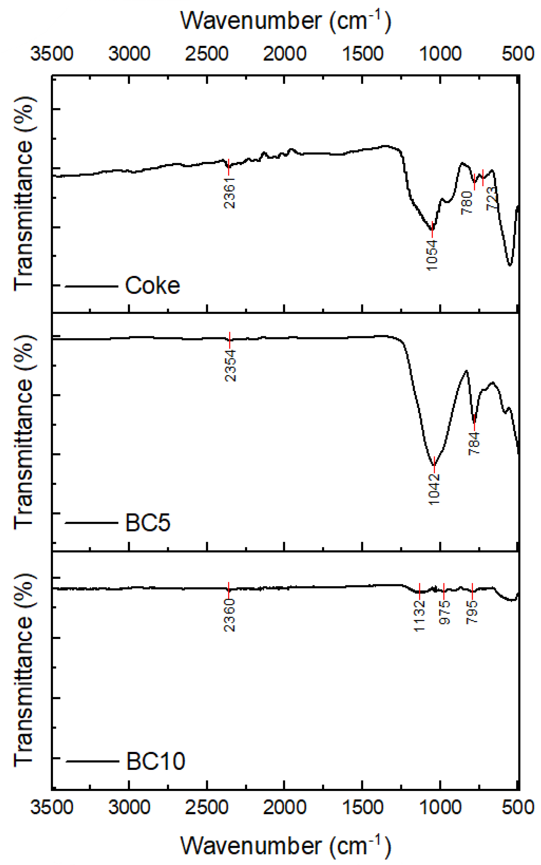
According to FTIR analysis, for biocoke with 10 wt.% wood pellets, the intensity of the peaks is very weak compared to coke or biocoke with 5 wt.% wood pellets, indicating that biocoke with 10 wt.% wood pellets has almost entirely reacted with air oxygen.
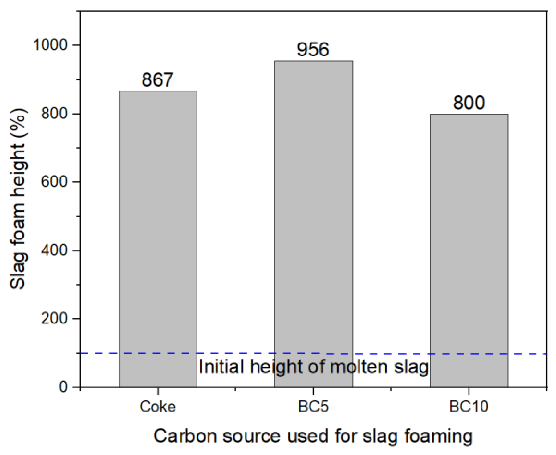
The applicability of biocoke for facilitating foaming slag was confirmed, marked by stable foaming and increased volume and height, without an uncontrollable change in the slag foaming characters. Comparatively, the relative foaming volume, ΔV/V0, was improved for biocoke with 5 wt.% wood pellets in contrast to coke. However, the utilization of biocoke with 10 wt.% wood pellets exhibited marginally less foaming compared to coke. The introduction of 5 wt.% wood pellets increased the reaction rate, reducing slag foaming time. Conversely, adding 10 wt.% wood pellets significantly decreased foaming time, limiting this process.
This study emphasizes that the influence of carbon sources is a complex consideration, with various factors affecting the overall behavior. Characters such as ash content, volatile matters, fixed carbon value, and microstructural features of carbon sources are important and should be considered. However, based on the results, the reactivity of carbon sources as a complex of qualitative characteristics is of great importance. Therefore, the thermochemical properties of carbon sources should be considered when evaluating the applicability of unconventional carbon sources for slag foaming.

Author Contributions

Conceptualization, L.K. and J.S.; methodology, L.K. and J.S.; investigation, L.K., A.K. and A.H.; writing—original draft preparation, L.K.; writing—review and editing, J.S.; supervision, J.S. All authors have read and agreed to the published version of the manuscript.

Funding

This research received no external funding.

Data Availability Statement

Relevant data are contained within the article.

Acknowledgments

This work was supported by the scholarship program “Scholarship of the Scholarship Foundation of the Republic of Austria, Postdocs”, [MPC-2022-02241], financed by the Federal Ministry of Education, Science and Research of Austria, which is gratefully acknowledged. We would like to acknowledge the staff of the Chair of Ferrous Metallurgy, who supported us throughout this research.

Conflicts of Interest

Author Lina Kieush was employed by the company K1-MET GmbH. The remaining authors declare that the research was conducted in the absence of any commercial or financial relationships that could be construed as a potential conflict of interest.

Correction Statement

This article has been republished with a minor correction to resolve typographical errors. This change does not affect the scientific content of the article.

References

  1. Axelson, M.; Oberthür, S.; Nilsson, L.J. Emission Reduction Strategies in the EU Steel Industry: Implications for Business Model Innovation. J. Ind. Ecol. 2021, 25, 390–402. [Google Scholar] [CrossRef]
  2. Hara, S.; Ogino, K. Slag-Foaming Phenomenon in Pyrometallurgical Processes. ISIJ Int. 1992, 32, 81–86. [Google Scholar] [CrossRef]
  3. Luz, A.P.; Avila, T.A.; Bonadia, P.; Pandolfelli, V.C. Slag Foaming: Fundamentals, Experimental Evaluation and Application in the Steelmaking Industry. Refract. Worldforum 2011, 3, 91–98. [Google Scholar]
  4. Agnihotri, A.; Singh, P.K.; Singh, D.; Gupta, M. Foamy Slag Practice to Enhance the Energy Efficiency of Electric Arc Furnace: An Industrial Scale Validation. Mater. Today Proc. 2021, 46, 1537–1542. [Google Scholar] [CrossRef]
  5. Morales, R.D.; Rubén, L.G.; López, F.; Camacho, J.; Romero, J.A. The Slag Foaming Practice in EAF and Its Influence on the Steelmaking Shop Productivity. ISIJ Int. 1995, 35, 1054–1062. [Google Scholar] [CrossRef]
  6. Matsuura, H.; Fruehan, R.J. Slag Foaming in an Electric Arc Furnace. ISIJ Int. 2009, 49, 1530–1535. [Google Scholar] [CrossRef]
  7. Vieira, D.; Almeida, R.A.M.D.; Bielefeldt, W.V.; Vilela, A.C.F. Slag Evaluation to Reduce Energy Consumption and EAF Electrical Instability. Mat. Res. 2016, 19, 1127–1131. [Google Scholar] [CrossRef]
  8. Huang, X.-A.; Ng, K.W.; Giroux, L.; Duchesne, M. Carbonaceous Material Properties and Their Interactions with Slag During Electric Arc Furnace Steelmaking. Met. Mater. Trans. B 2019, 50, 1387–1398. [Google Scholar] [CrossRef]
  9. Kieush, L.; Koveria, A.; Boyko, M.; Yaholnyk, M.; Hrubiak, A.; Molchanov, L.; Moklyak, V. Influence of Biocoke on Iron Ore Sintering Performance and Strength Properties of Sinter. Min. Min. Depos. 2022, 16, 55–63. [Google Scholar] [CrossRef]
  10. Solar, J.; Hernandez, A.; Lopez-Urionabarrenechea, A.; De Marco, I.; Adrados, A.; Caballero, B.M.; Gastelu, N. From Woody Biomass Waste to Biocoke: Influence of the Proportion of Different Tree Components. Eur. J. Wood Prod. 2017, 75, 485–497. [Google Scholar] [CrossRef]
  11. Koveria, A.; Kieush, L.; Svietkina, O.; Perkov, Y. Metallurgical Coke Production with Biomass Additives. Part 1. A Review of Existing Practices. Can. Metall. Q. 2020, 59, 417–429. [Google Scholar] [CrossRef]
  12. Montiano, M.G.; Díaz-Faes, E.; Barriocanal, C.; Alvarez, R. Influence of Biomass on Metallurgical Coke Quality. Fuel 2014, 116, 175–182. [Google Scholar] [CrossRef]
  13. Hu, M.; Chen, Z.; Wang, S.; Guo, D.; Ma, C.; Zhou, Y.; Chen, J.; Laghari, M.; Fazal, S.; Xiao, B.; et al. Thermogravimetric Kinetics of Lignocellulosic Biomass Slow Pyrolysis Using Distributed Activation Energy Model, Fraser–Suzuki Deconvolution, and Iso-Conversional Method. Energy Convers. Manag. 2016, 118, 1–11. [Google Scholar] [CrossRef]
  14. Chen, X.; Liu, L.; Zhang, L.; Zhao, Y.; Qiu, P. Pyrolysis Characteristics and Kinetics of Coal–Biomass Blends during Co-Pyrolysis. Energy Fuels 2019, 33, 1267–1278. [Google Scholar] [CrossRef]
  15. Chen, W.-H.; Wu, J.-S. An Evaluation on Rice Husks and Pulverized Coal Blends Using a Drop Tube Furnace and a Thermogravimetric Analyzer for Application to a Blast Furnace. Energy 2009, 34, 1458–1466. [Google Scholar] [CrossRef]
  16. Xu, J.; Zuo, H.; Wang, G.; Zhang, J.; Guo, K.; Liang, W. Gasification Mechanism and Kinetics Analysis of Coke Using Distributed Activation Energy Model (DAEM). Appl. Therm. Eng. 2019, 152, 605–614. [Google Scholar] [CrossRef]
  17. Yang, T.; Wei, B.; Wang, S.; Liu, W.; Chen, L.; Wang, J.; Abudureheman, M.; Ma, J.; Wang, F. Effect of Particle Size on the Kinetics of Pure Oxygen Combustion of Coke. Thermochim. Acta 2023, 719, 179405. [Google Scholar] [CrossRef]
  18. Qin, Y.; Ling, Q.; He, W.; Hu, J.; Li, X. Metallurgical Coke Combustion with Different Reactivity under Nonisothermal Conditions: A Kinetic Study. Materials 2022, 15, 987. [Google Scholar] [CrossRef]
  19. Fidalgo, B.; Berrueco, C.; Millan, M. Chars from Agricultural Wastes as Greener Fuels for Electric Arc Furnaces. J. Anal. Appl. Pyrolysis 2015, 113, 274–280. [Google Scholar] [CrossRef]
  20. Cardarelli, A.; De Santis, M.; Cirilli, F.; Barbanera, M. Computational Fluid Dynamics Analysis of Biochar Combustion in a Simulated Ironmaking Electric Arc Furnace. Fuel 2022, 328, 125267. [Google Scholar] [CrossRef]
  21. Wei, R.; Zheng, X.; Zhu, Y.; Feng, S.; Long, H.; Xu, C.C. Hydrothermal Bio-Char as a Foaming Agent for Electric Arc Furnace Steelmaking: Performance and Mechanism. Appl. Energy 2024, 353, 122084. [Google Scholar] [CrossRef]
  22. Son, K.; Lee, J.; Hwang, H.; Jeon, W.; Yang, H.; Sohn, I.; Kim, Y.; Um, H. Slag Foaming Estimation in the Electric Arc Furnace Using Machine Learning Based Long Short-Term Memory Networks. J. Mater. Res. Technol. 2021, 12, 555–568. [Google Scholar] [CrossRef]
  23. Yunos, N.F.M.; Zaharia, M.; Ismail, A.N.; Idris, M.A. Transforming Waste Materials as Resources for EAF Steelmaking. Int. J. Mater. Eng. 2014, 4, 167–170. [Google Scholar]
  24. Zhang, Y.; Fruehan, R.J. Effect of the Bubble Size and Chemical Reactions on Slag Foaming. Met. Mater Trans. B 1995, 26, 803–812. [Google Scholar] [CrossRef]
  25. Luz, A.P.; Tomba Martinez, A.G.; López, F.; Bonadia, P.; Pandolfelli, V.C. Slag Foaming Practice in the Steelmaking Process. Ceram. Int. 2018, 44, 8727–8741. [Google Scholar] [CrossRef]
  26. Menad, N.-E.; Kana, N.; Seron, A.; Kanari, N. New EAF Slag Characterization Methodology for Strategic Metal Recovery. Materials 2021, 14, 1513. [Google Scholar] [CrossRef]
  27. ASTM D3172-13; Standard Practice for Proximate Analysis of Coal and Coke 2013. ASTM International: West Conshohocken, PA, USA, 2013.
  28. Gudenau, H.W.; Senk, D.; Fukada, K.; Babich, A.; Froehling, C. Coke Behaviour in the Lower Part of BF with High Injection Rate. In International BF Lower Zone Symposium; Illawarra Branch: Wollongong, Australia, 2002. [Google Scholar]
  29. Kieush, L.; Koveria, A.; Schenk, J.; Rysbekov, K.; Lozynskyi, V.; Zheng, H.; Matayev, A. Investigation into the Effect of Multi-Component Coal Blends on Properties of Metallurgical Coke via Petrographic Analysis under Industrial Conditions. Sustainability 2022, 14, 9947. [Google Scholar] [CrossRef]
  30. Kieush, L.; Schenk, J. Investigation of the Impact of Biochar Application on Foaming Slags with Varied Compositions in Electric Arc Furnace-Based Steel Production. Energies 2023, 16, 6325. [Google Scholar] [CrossRef]
  31. Kieush, L.; Schenk, J.; Koveria, A.; Hrubiak, A.; Hopfinger, H.; Zheng, H. Evaluation of Slag Foaming Behavior Using Renewable Carbon Sources in Electric Arc Furnace-Based Steel Production. Energies 2023, 16, 4673. [Google Scholar] [CrossRef]
  32. Lu, J.-J.; Chen, W.-H. Investigation on the Ignition and Burnout Temperatures of Bamboo and Sugarcane Bagasse by Thermogravimetric Analysis. Appl. Energy 2015, 160, 49–57. [Google Scholar] [CrossRef]
  33. Coats, A.W.; Redfern, J. Kinetic Parameters from Thermogravimetric Data. Nature 1964, 201, 68. [Google Scholar] [CrossRef]
  34. Tang, L.; Xiao, J.; Mao, Q.; Zhang, Z.; Yao, Z.; Zhu, X.; Ye, S.; Zhong, Q. Thermogravimetric Analysis of the Combustion Characteristics and Combustion Kinetics of Coals Subjected to Different Chemical Demineralization Processes. ACS Omega 2022, 7, 13998–14008. [Google Scholar] [CrossRef] [PubMed]
  35. Okolo, G.N.; Neomagus, H.W.J.P.; Everson, R.C.; Roberts, M.J.; Bunt, J.R.; Sakurovs, R.; Mathews, J.P. Chemical–Structural Properties of South African Bituminous Coals: Insights from Wide Angle XRD–Carbon Fraction Analysis, ATR–FTIR, Solid State 13 C NMR, and HRTEM Techniques. Fuel 2015, 158, 779–792. [Google Scholar] [CrossRef]
  36. Warren, B.E. X-Ray Diffraction in Random Layer Lattices. Phys. Rev. 1941, 59, 693–698. [Google Scholar] [CrossRef]
  37. Wang, J.; Wang, W.; Chen, X.; Bao, J.; Duan, L.; Xu, R.; Zheng, H. Investigation on the Evolution of Structure and Strength of Iron Coke during Carbonization: Carbon Structure, Pore Structure, and Carbonization Mechanism. Powder Technol. 2024, 431, 119059. [Google Scholar] [CrossRef]
  38. Zheng, H.; Xu, R.; Zhang, J.; Daghagheleh, O.; Schenk, J.; Li, C.; Wang, W. A Comprehensive Review of Characterization Methods for Metallurgical Coke Structures. Materials 2021, 15, 174. [Google Scholar] [CrossRef] [PubMed]
  39. Fu, X.; Pang, Q.; Yang, X.; Zhan, W.; He, Z. Effect of High Temperature on Macroscopic Properties and Microstructure of Metallurgical Coke. Fuel 2024, 356, 129543. [Google Scholar] [CrossRef]
  40. Ochoa, A.; Ibarra, Á.; Bilbao, J.; Arandes, J.M.; Castaño, P. Assessment of Thermogravimetric Methods for Calculating Coke Combustion-Regeneration Kinetics of Deactivated Catalyst. Chem. Eng. Sci. 2017, 171, 459–470. [Google Scholar] [CrossRef]
  41. DiGiovanni, C.; Li, D.; Ng, K.W.; Huang, X. Ranking of Injection Biochar for Slag Foaming Applications in Steelmaking. Metals 2023, 13, 1003. [Google Scholar] [CrossRef]
  42. Ng, K.W.; MacPhee, J.A.; Giroux, L.; Todoschuk, T. Reactivity of Bio-Coke with CO2. Fuel Process. Technol. 2011, 92, 801–804. [Google Scholar] [CrossRef]
  43. Suopajärvi, H.; Dahl, E.; Kemppainen, A.; Gornostayev, S.; Koskela, A.; Fabritius, T. Effect of Charcoal and Kraft-Lignin Addition on Coke Compression Strength and Reactivity. Energies 2017, 10, 1850. [Google Scholar] [CrossRef]
  44. Ogawa, Y.; Katayama, H.; Hirata, H.; Tokumitsu, N.; Yamauchi, M. Slag Foaming in Smelting Reduction and Its Control with Carbonaceous Materials. ISIJ Int. 1992, 32, 87–94. [Google Scholar] [CrossRef]
  45. Oh, J.S.; Lee, J. Composition-Dependent Reactive Wetting of Molten Slag on Coke Substrates. J. Mater. Sci. 2016, 51, 1813–1819. [Google Scholar] [CrossRef]
  46. Migas, P.; Karbowniczek, M. Interactions between Liquid Slag and Graphite During the Reduction of Metallic Oxides. Arch. Metall. Mater. 2010, 55, 1147–1157. [Google Scholar] [CrossRef]
  47. Sahajwalla, V.; Khanna, R.; Rahman, M.; Saha-Chaudhury, N.; Knights, D.; O’Kane, P.; Association for Iron & Steel Technology. Recycling of Waste Plastics for Slag Foaming in EAF Steelmaking. In Proceedings of the AISTech—Iron and Steel Technology Conference Proceedings, Cleveland, OH, USA, 1–4 May 2006; Volume 2. [Google Scholar]
Figure 1. TG-DTG curves of carbon source combustion under air: (a) coke; (b) BC5; and (c) BC10. Assignments of characters are given within the text.
Metals 14 00013 g001
Figure 2. Arrhenius curves calculated for three carbon sources.
Metals 14 00013 g002
Figure 3. FTIR spectra of three carbon sources after combustion. Assignments of peaks are given within the text.
Metals 14 00013 g003
Figure 4. Slag foaming formation after adding carbon source: (a) coke; (b) BC5; (c) BC10.
Metals 14 00013 g004
Figure 5. Changes in slag foam height depending on the carbon source applied.
Metals 14 00013 g005
Table 1. Slag composition.
SampleFeO, wt.%CaO, wt.%SiO2, wt.%MgO, wt.%Al2O3, wt.%TotalB2B3
29.035.017.010.09.0100.02.01.3
B2, basicity CaO/SiO2; B3, basicity CaO/(SiO2 + Al2O3).
Table 2. Characters of carbon sources.
CharactersCokeBC5BC10
Proximate analysis, wt.%
M0.770.660.65
VM (db)1.461.401.42
VM (daf)1.481.421.44
Ash (db)11.110.810.5
Cfix (db)87.487.888.1
Higher heating value, MJ/kg
HHV 29.5729.5929.63
Elemental analysis, wt.%
S (db)1.361.281.20
C (db)84.5184.7485.05
H (db)0.300.270.22
N (db)1.101.061.02
* Others, mainly O (db)1.631.852.01
Characteristic of microstructural parameter, nm
d0020.360.350.35
La3.602.983.04
M, moisture; VM, volatile matters; C, carbon; H, hydrogen; N, nitrogen; S, sulfur; db, dry basis; daf, dry ash-free basis; VM(daf) = VM(db)·100/(100 − Ash(db,%)); Cfix, wt.% = 100 − (wt.% VM(db) − wt.% Ash(db)); calculated by HHV = 0.3491 · C + 1.1783 · H + 0.1005 · S − 0.0151 · N − 0.1034 · O − 0.0211 · Ash. * Calculated by difference; d002, aromatic planes of carbon crystallites; La, carbon crystallite width.
Table 3. Amount of carbon source based on fixed carbon for required reduction.
SampleCoke,
g
BC5,
g
BC10,
g
Stoichiometrically required amount5.535.505.49
Table 4. Combustion characteristics of carbon source samples.
Combustion CharacteristicsCokeBC5BC10
Ignition temperature Ti, °C530558559
Peak temperature Tp, °C634675665
Burnout temperature Tf, °C758701735
T, °C228143176
Weight loss, wt.%73.083.686.4
Table 5. Slag foaming characters based on a single test for each carbon source.
Slag CharactersMolten Slag
Initial slag height
mean hslag, cm
0.9
Initial slag volume
mean Vslag, cm3
28.04
Slag foaming charactersSF (Coke)SF (BC5)SF (BC10)
Slag foam height
hfoam, cm
7.88.67.2
Time of slag foaming, s ~ 580 ~ 417 ~ 185
Slag foam volume
Vfoam, cm3
243.02267.94224.33
Relative foaming volume, ΔV/V07.678.567.00
Disclaimer/Publisher’s Note: The statements, opinions and data contained in all publications are solely those of the individual author(s) and contributor(s) and not of MDPI and/or the editor(s). MDPI and/or the editor(s) disclaim responsibility for any injury to people or property resulting from any ideas, methods, instructions or products referred to in the content.

