Review

Laser Beam Machining of Titanium Alloy—A Review

by
Alokesh Pramanik
1,* and
Animesh Kumar Basak
2,*
1
School of Civil and Mechanical Engineering, Curtin University, Bentley, WA 6102, Australia
2
Adelaide Microscopy, The University of Adelaide, Adelaide, SA 5000, Australia
*
Authors to whom correspondence should be addressed.
Metals 2023, 13(9), 1536; https://doi.org/10.3390/met13091536
Submission received: 29 June 2023 / Revised: 11 August 2023 / Accepted: 28 August 2023 / Published: 30 August 2023

Abstract

:
This study investigates the laser beam machining mechanism, surface formation mechanisms, heat-affected zone, taper formation, and the dimensional deviation of the titanium alloy, based on the information available in literature. The heat induced by the laser beam melts and vaporises titanium alloy, which is removed by a high pressure-assisted gas. The machined titanium alloy surface is expected to have craters and resolidified materials which were contributed by the low thermal conductivity of the titanium alloy. Taper and circularity error can be minimised by optimising the laser parameter, but it cannot be avoided in the laser beam machining of titanium alloy. Laser beam machining induces a non-diffusion phase transformation, which slightly changes the surface mechanical properties of the titanium alloys. Laser beam machining is gaining popularity as a way to improve the surface finish quality and properties of titanium components manufactured by additive manufacturing processes. To enhance the machining efficacy of titanium alloys, several hybrid machining processes were proposed.

1. Introduction

Machining of materials is an integral part of the components in the manufacturing process, where desired final shape, size, and surface requirements are achieved. Traditional or conventional machining of metals and alloys cuts materials by the generation of shear force that plastically deforms the materials, for instance, formation of chip (turning milling, etc.), micro-chipping (blasting, etc.), and abrasion (grinding, lapping, etc.). Nevertheless, conventional machining techniques are expensive to apply for hard-to-machine materials, for example, metal matrix composites, and alloys of titanium and nickel in particular [1]. This is because of extended machining time, higher tool wear, and difficulties in shaping parts with complex geometry. Usually, titanium and its alloys possess higher strength-to-weight proportion, better protection from corrosion, greater fatigue performance, and endure moderately higher temperatures without creeping [2], which are categorised as hard-to-machine materials. Furthermore, small elastic modulus, lower heat conductivity, and greater chemical acuteness at higher temperatures increase the machining cost of titanium alloy. Metallurgical uniqueness of these materials make it more difficult and expensive for machining, compared to that of steel with comparable hardness range [3]. The biphasic α/β Ti-6Al-4V alloy exhibits boosted mechanical and metallurgical behaviours, which are added advantages to numerous fields amongst other Ti-alloys, due to its greater strength at higher temperature, toughness, and resistance against abrasion and corrosion [4,5]. Table 1 shows a comparison of the conventional machinability of several Ti-alloys compared to other metals. The rating of machinability of a material is the ease of machining to obtain the expected finish. The American Iron and Steel Institute (AISI) proposed the machinability rating depending on the weighted average of cutting speed, surface finish, and tool life for turning of respective material. It is based on turning tests at speed 180 rpm where 160 Brinell B-1112 steel is assigned as 100% machinability rating [6]. Despite reduced machinability, Ti-alloys are employed broadly in medicinal, space engineering, maritime, chemical treating, and automobile industries [7].
The rising demand of Ti-alloys in high-tech fields inevitably requires non-conventional machining techniques for shaping parts of these materials. There is much research on many technologies for improving machinability of difficult-to-machine materials [9,10,11]. Among different non-conventional machining of Ti-alloys, electro discharge machining (EDM) is widely employed which is, in principle, a heat-assisted process [12,13,14]. In some instances, laser beam machining of Ti-alloys was also reported, however, to a much lesser extent.
Thus, the aim of the present review is to obtain a comprehensive understanding of the machinability of Ti-alloy via laser beam machining. This review will provide an understanding about the beam–material interaction, the effect of beam characteristics on the surface generated by the laser beam, the recast layer formation, and the material removal mechanism. Together with the critical analysis of the information available in the literature, several recommendations for future work were also reported to fill the present knowledge gap. This comprehensive overview will guide the researchers to make future contributions in this field to make it more applicable for different bespoke applications.

2. Laser Beam Machining (LBM)

LBM is an extensively applied non-contact non-conventional material removal technique that uses thermal energy. As the name suggests, in this method a beam of laser is concentrated on the workpiece where heat is generated and material is detached through vaporising and melting [1,15]. Therefore, machining forces, tool wear, mechanically induced surface damage, vibration, and electro-related factors (such as voltage, electrodes, spark, electrolyte, etc.) are absent in this case [16]. LBM can be employed for drilling and cutting of different workpieces, such as non-metals, metals, and composites which are appropriate to produce shapes and tiny holes in sheet metal with cut opening (kerf width) as low as 0.25 mm [17]. Laser drilling could be performed by percussion, trepanning, or single shot drilling methods. High strength laser pulses vaporise and melt the workpiece in the percussion drilling. Conversely, a focused laser beam is applied in trepanning to remove the required region of the workpiece which is more appropriate for creating holes with larger diameter [18]. Generally, several pulses might be essential to complete thorough drilling of workpieces which depends on pulse energy, material properties, and workpiece thickness. Improved quality holes are machined efficiently by using multiple laser pulses of low energy rather than one pulse of high energy [19].

2.1. Type of Laser Beam

Laser machining affects the material removal rate and quality of the machined surface. The key factors include laser type, laser beam property, substrate material, debris removal system, and laser procedure variables.
The most commonly used lasers are Nd: YAG and CO2 types in the LBM process [1]. The gas laser CO2 releases light in the infrared region which has pulse and is continuous in forms. This laser has a wavelength of 10 µm in the infrared area, good quality beam, large beam power (average), and decent efficacy that are appropriate for satisfactory machining of sheet metal efficiently [20]. The solid-state Nd: YAG laser delivers light through a fiber-optic cable. This laser has lower mean power, but during its use in pulsed mode offers great peak power, improved focusing features, thin width of kerf, and reduced heat-affected region. However, the beam of CO2 laser is generally applied for machining metal sheets in productions whereas Nd: YAG is applied for high-accuracy machining [1]. Due to the shorter wavelength (1.064 μm) of Nd:YAG laser, it reflects from a smaller area of the workpiece surfaces which empowers machining of reflective materials. Materials with higher thermal conductivity provide holes of worse characteristics while drilling by CO2 laser. Because of a briefer thermal interface period, Nd: YAG laser provides improved outcomes. In pulsed form, large instance peak power enables drilling of a thicker workpiece [21,22]. There are only a few reports available in literature on the laser beam machining of titanium alloy. The machinability in this method primarily relies on the thermal and optical characteristics instead of the tensile behaviour of workpieces [23]. Thermal conductivity, reflectiveness, specific and latent heats are significant properties of the workpiece that affect the efficiency of the LBM process. Therefore, brittle and hard materials could be machined by LBM [7]. However, this process becomes complex due to the poor heat conduction and excessive chemical acuteness of titanium alloys at elevated temperatures [7].
Figure 1 shows a graphic presentation of a laser beam which is produced by a laser source as mentioned above. After that, the laser beam passes through a focusing lens to converge the laser. This lens also determines the spot size and focal distance of the laser. By varying the power of the lens, the focal length and spot size can be varied accordingly to serve the need. The tapers on laser machined parts exist because of the diverging–converging form of the laser beam (Figure 1).

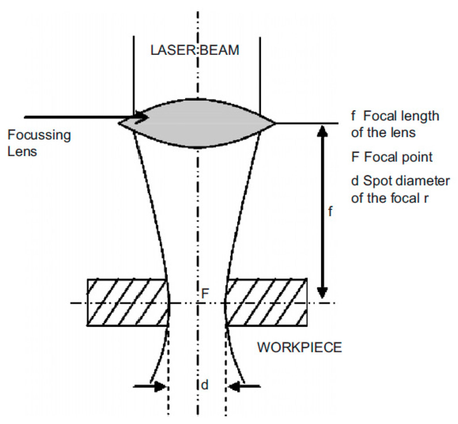
2.2. Principal of LBM

There are three process stages during LBM processing of any materials: (a) melting, vaporising, and chemical degradation, (b) removal of degraded materials, and (c) cool down of the workpiece material after the process. Thermal energy of the laser beam increases the temperature and changes the workpiece into semi-molten and vaporised stages, locally [1]. The jet of air/gas at high pressure is applied to take away the molten/semi-molten materials from the machining zone and it also prevents oxidation [1,24]. Then, the machined parts cool down to room temperature. In the case of titanium alloys, localised high temperature takes a longer time to cool down as these alloys have very low thermal conductivity. Laser machining could be attached to a robot or multiple-axis machine while machining complex parts [23,25]. This facilitates the application of LBM with high precision at higher speed. Figure 2 presents a schematic diagram of a complex LBM system. The efficiency of LBM is controlled by the thermal and optical behaviour of the workpiece instead of the deformation behaviours of the material itself. Thus, brittle and hard materials which exhibit lower heat conductivity and diffusivity are predominantly suitable for LBM. The transfer of energy between the laser beam and workpieces happens by irradiation, where machining forces are not present. These prevent mechanically produced damage in the workpiece, wear of cutting tool, and vibrations. Furthermore, the rate of material removal during LBM is not restricted by the highest machining forces, built-up-edge, and chatter. LBM is an adaptable procedure which can be applied to fabricate groove, cut, drill, weld, and heat treatment in one step [26].
Drilling by laser beam is recognised as a cost-effective procedure for producing hundreds of narrowly spread-out holes in workpieces. Trepan and percussion are two types of laser beam drilling. The cutting takes place along the perimeter to produce the hole in trepan drilling while percussion punches across the workpiece without any relative motion between the workpiece and laser. The main characteristic of the percussion-type hole is the reduced machining time [25]. The grooving and cutting processes are applied in cut-off, punching, and making pattern on composites, non-metals, and metals. The cutting process by laser beam has advantages over any traditional or non-traditional cutting techniques due to workpiece flexibility and machining efficiency.

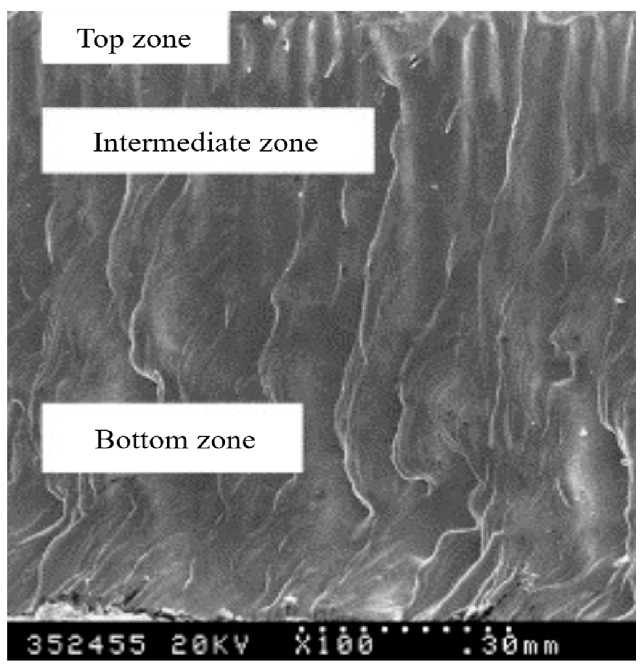
2.3. Characteristics of the Surface Generated by LBM

The laser beam removes material by ablation and generates craters on the surface. The crater size and material removal depend on the distribution of laser energy [15]. A part of the melted material resolidifies as recast layer on the machined surface. The layer of material existing just below the recast layer is significantly affected by the process which is known as the heat-affected zone (HAZ) [27]. Increased laser power and reduced nozzle distance give a higher surface finish due to the generation of smaller craters and reduced particle adhesion [28]. The laser micro-milling technique is used to manufacture microchannels on metals and nonmetals. Microfeatures ≤ 100 µm on titanium can be produced through micromachining by employing a nanosecond fiber laser [29]. Femtosecond fiber lasers (5 W with 1032 nm wavelength and 500 fs pulse duration) can be applied for micromachining to provide superior final finish (Ra = 0.8 μm) of additively manufactured titanium parts [30]. Obeidi et al. [31] polished additively manufactured flat and cylindrical Ti-6Al-4V parts using a low-power CO2 laser for a smoother surface and improved fatigue resistance. The laser polishing process reduced roughness (Ra) and peak-to-valley distance (Rz) by 80% and 90%, respectively. Lee et al. [32] noted improved high-cycle fatigue performance of the laser polished parts because of improved surface finish.
LBM of titanium alloys generates heat-affected zone (HAZ) at the machined surface where the structure of titanium alloys changes significantly [33]. The HAZ forms in the region of the disintegration front because of the high temperature and cooling rate in the top layer of the machined surface. Figure 3a shows a typical surface generated from argon-assisted LAM of titanium alloy where the kerf width and HAZ thickness are 160 and 20 µm, respectively [33].
In this case, the temperature reached in between the melting point and beta-transformation temperature during LBM [33]. The machined surface experiences a high cooling rate as the laser beam travels away because of the cooling due to gas jet and heat conduction to the workpiece material. A non-diffusion change of phase happens ensuing metastable acicular martensite structure as presented in Figure 3b when the temperature reduces to that of beta-transformation temperature. Although martensitic changes in steel cause severe lattice distortion with substantial rise of stiffness and hardness, it results in the consequence of only an insignificant rise of hardness in the case of titanium alloys [33]. The plasma energy at nozzle diameter 1.2 mm, laser power 2 kw, focal length +2 mm, and O2 gas pressure of 4 bar gives decreased residual stress and fewer micro-cracks on the machined surface [27].
A surface machined by laser commonly has three regions: (a) top, (b) intermediate, and (c) bottom zone as shown in Figure 4 [33]. The initialization region of machining is the top zone which is a few microns in width. The top zone inclines to be widespread with the rise of pulse energy as it is comparatively flat with slight stripe undulations.
The intermediate zone consists of primary striations which are consistent and exhibit the rate of recurrence like that of laser pulses. These do not spread to the bottom of the kerf. The laser pulses weaken, and gas flow dominates surface morphology with the deepening of the metal sheet thickness. Thus, the bottom zone owns a surface of uneven waves. The bottom zone narrows down, and the top zone widens as the pulse energy rises. The top zone width increases from 28 to 100 μm as the pulse energy rises from 1.5 to 3.0 J, keeping other parameters constant at 20 Hz pulse rate, 0.8 MPa Ar pressure, and 1 mm/s machining speed. Insignificant undulation of machined surface was attained at 20–30 Hz pulse frequency; however, significant ripple appeared at 40 and 10 Hz pulse energy [33].
The quality of the LBM-generated surface depends largely on assisting gas as shown in Figure 5. Ar-supported laser machining generates a ripple of primary striations, and the surface of which stretches with micro-ripples as presented in Figure 5a. These micro-ripples are generated from the collective influences of aiding gas and the capillary force of melted material. When the laser cut is air-assisted, the number of micro-cracks could be detected on the surface of the titanium alloy, as given in Figure 5b. The lengths of the micro cracks reduce as the cutting speed rises. The prime causes of these micro-cracks’ generation are as follows: (a) the brittle by-products, for example, titanium oxide and titanium nitride, and (2) the tensile residual stress generated on the machined surface [15].
It has already been mentioned that the fast heating up and cooling down induce a quenching effect, and the machined surface cools down much quicker than the matrix and thus generates tensile residual stress. Furthermore, chemical reactions of titanium with nitrogen and oxygen embrittle the machined surface. The cracks are generated as soon as the tensile stress exceeds yield stress [15]. The surfaces generated from nitrogen-aided laser machining appear as light yellow and contain numerous micro-grains demonstrating the reaction between titanium and nitrogen (Figure 5c). The grain number of titanium nitride decreased with the rise of gas pressure, and surfaces generally comprise only primary striations when the pressure of gas goes beyond 0.8 MPa.
Air- and nitrogen-assisted LBM meaningfully degrade the corrosion and mechanical properties of titanium parts. The frequency of pulses, which increases with the increase in pulse energy, is the utmost influential parameter trailed by machining speed on the quality of the machined surface during N2-assisted pulsed Nd:YAG LBM of Ti-6Al-4V alloy [7]. The irregularity in the surface machined by laser rises by raising the speed at a lesser frequency of pulses but at greater frequency, roughness reduces with the increase speed. The ‘spot overlapping extent’ affects more on roughness during the pulsed mode of laser cutting. Larger spot overlapping induces better surface finish. The amalgamation of cutting speed and frequency of laser pulses primarily controls the ‘spot overlapping extent’. Slower machining speed generates a higher degree of spot overlapping, and unceasing density of power per unit distance provides an even smoother surface finish. In contrast, at a faster speed when pulse frequencies are shorter, it generates lower overlapping of spots, intermittent density of power, and lesser melting time which gives a rougher surface [7].
Ahmed et al. [34] investigated the influence of scanning speed, pulse frequency, laser intensity, thickness of laser scan, and displacement of succeeding laser tracks on surface roughness and material removal rate during laser milling of Ti-6Al-4V. The optimum milling for 100% MRR and least surface finish (Ra = 0.965 μm) occurred at pulse frequency of 10.33 kHz; scanning speed of 250 mm/s; laser intensity of 75%; layer thickness of 1.11 μm, and track displacement of 12 μm [34]. Pramanik et al. [15] investigated pulsed diode pumped fiber laser sawing of titanium alloy sheet at low power (50 watt) at varied sawing angle. It was noted that the least 0.4244° kerf taper and 2.29 µm surface roughness (Ra) can be obtained at 0.3462° sawing angle, 46.98 W power, 95.06% duty cycle, and 52.90 kHz pulse frequency at 0.56 mm/s scanning speed.

2.4. Role of Input Parameters during LBM on Surface Characteristics

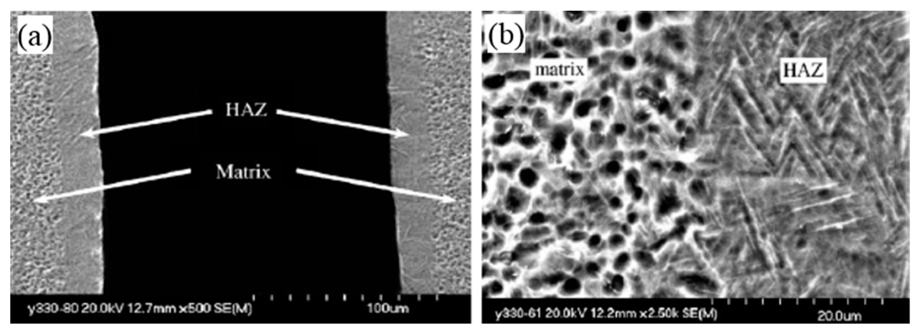
2.4.1. Heat-Affected Zone (HAZ)

Laser pulse energy, laser mode, laser type, assisted gas pressure and machining speed significantly influence the HAZ thickness during the process. The impact of energy of pulse on HAZ thickness is presented in Figure 6a. Pulse energies of 1.5 and 2.5 J generated around 10 µm thick HAZ. A thicker HAZ was noted under and above 1.5 and 2.5 J, correspondingly. At lower energy, narrow kerf width limits the cleaning ability of assisted gas which let additional melt materials stick on kerf surfaces, thus more heat conducted to the workpiece. Consequently, pulse energy lower than 1.5 J is likely to produce thicker HAZ layer. Higher energy is accumulated on the material at increased pulse energy above 2.5 J. This transmits more energy to the material and results in thicker HAZ [33]. Figure 6b presents that the thickness of HAZ decreases as the machining speed rises, irrespective of gas used for cleaning and cooling. However, the application of argon gas generated thinner HAZ compared to that of compressed air. A lower energy density is experienced by the workpiece at higher cutting speeds which transmits less heat in the workpiece and thus reduces the HAZ thickness. Argon gas keeps the HAZ cleaner due to its chemical inertness compared to compressed air. Figure 6c presents the influence of pressure of various gases on the thickness of HAZ. The high-pressure gas decreases the thickness of HAZ through a cooling effect [33]. Oxygen induces an uncontrollable burning at the cutting front which gives wider kerfs. Thus, oxygen is unsuitable for the pulsed laser machining of titanium alloys even at lower pressure. A thinner layer of brittle and hard nitride and oxide is formed in air-assisted laser cutting because of reactions of titanium with nitrogen and oxygen, and gives thicker HAZ at higher heat input. An evaluation of HAZ thickness with compressed air, argon, and nitrogen is presented in Figure 6c. Nitrogen-aided laser gives a light-yellow machined surface due to the presence of titanium nitride which forms due to a chemical reaction between titanium and nitrogen. On the other hand, argon-assisted LBM gives a silver-white surface appearance [33,35]. The surfaces generated from He, Ar, and mixture of those assisted LBM do not contain nitrides and probably do not experience significant change in hardness [35].
Pulse width and the pressure of aided gas affect the kerf taper considerably during N2-assisted pulsed Nd:YAG LBM of Ti-6Al-4V alloy [7]. As titanium alloys have lower thermal conductivity, the top surface burnt during LBM. This causes higher material removal from the top surface, and nitride forms because of the strong chemical affinity of titanium alloy at an elevated temperature. This nitride is deposited at the bottom of the cut and gives a narrower kerf compared to that at the top. Eventually, the variation amongst exit and entry widths of kerf rise and exhibit a larger taper in the slot [7]. The taper reduces as the pressure of aided gas rises at lesser width of the pulses. The kerf taper initially reduces and then rises as assisted gas pressure rises at a larger pulse width. The melted substance might be eliminated from the kerf at a lesser width of pulses and increased gas pressure. Greater penetration depth gives a wider kerf at the bottom at a lesser pulse and higher peak power [7]. Lower trepanning speed and pulse width together with higher assisted gas pressure and pulse frequency generate the least taper hole in 1.4 mm thick Ti-6Al-4V alloy during N2-assisted pulsed Nd:YAG laser LBM [36].
The lower rank of focal locations is advantageous during producing finer holes having smaller taper. However, drilling at lesser pulse energy necessitates many shots for drilling through the workpiece where lower removal of material occurs by each pulse as compared to that of higher pulse energy and subsequently, lesser hole-wall erosion. Shorter pulse duration also decreases taper compared to a prolonged pulse period. The latter extends the time of workpiece–laser contact and enhances the conduction of heat laterally which generates bigger hole diameter at the entry. More significantly, longer interaction time produces a larger volume of melt material and, hereafter, greater melt expulsion. This is accountable for higher wearing away of the hole wall close to the entrance. This results in a bigger hole diameter at the entrance [18,37].

2.4.2. Taper Formation

The dissimilarity in laser beam plasma arose due to the discharge deviation inside the holes. This gives improved geometrical accuracy at the hole entry. It was observed that the entry profiles of the holes have a better geometrical accuracy than the exit profiles of drilled holes [27]. The reduced laser power and nozzle distance with reasonable gas pressure increase accuracy and reduce taper [28].
The hole taper reduces as the frequency of pulse rises at lesser currents; in contrast, the taper of hole rises as the frequency of pulse rises at higher currents when the plate thickness and air pressure are persistent at 0.58 mm and 1.5 kg/cm2, respectively. This was the case during drilling holes in gamma-titanium aluminide plate by pulsed Nd:YAG laser during LBM and shown in Figure 7 [38]. The taper of hole rises significantly as the current rises regardless of the values of the frequency of pulse. Larger lamp current produces higher heat and consequently, the upper plane of the material, where the beam of laser is aimed, became vaporised and melted instantaneously. Therefore, a greater amount of material is removed from the surface at the top which gives larger diameter at the top and holes with larger taper. Nevertheless, lesser lamp current produces a lower taper. Increased pulse frequency and reduced off time of pulse provide too much pulse break through the workpiece at a lower lamp current. This causes the increase in diameter of the hole at the bottom and produces a hole with lesser taper. The gap between two consecutive laser beam incidents is smaller for a higher frequency of pulse. This removes more materials from the upper plane and produces holes with bigger taper at a higher lamp current. When the plate depth and frequency of pulse remain steady at 0.58 mm and 1.2 kHz, the taper rises with the rise of the lamp current. Initially, the taper reduces and then rises as a parabolic curve trend with the rise of assisted air pressure regardless of the lamp current. The increased assisted air pressure removes additional heat and as a result, the melted material solidifies at the entry of the hole. This allows lesser removal of material from the upper plane and reduces the taper of the hole with the rise of air pressure until a specific threshold is reached. Additional rise of pressure of air removes the molten workpiece material from the upper layers quickly, and accordingly, a hole with a bigger taper was produced [38]. Lamp current most significantly influences all outputs’ parameters during micro-drilling of gamma-titanium aluminide alloy by air-assisted Nd:YAG laser LBM. Pulse frequency dominates hole diameters; specimen thickness and air pressure dominate taper and hole size at bottom. The optimal hole size at bottom, at entry and taper of hole might be attained at greater frequency of pulse, moderate lamp current, higher pressure of air, and lower workpiece thickness [21]. The similar trends of the width of kerf with the variation of gas type, power, pressure, and machining speed as discussed earlier was observed when 1.2 mm austenitic stainless-steel sheet was cut by an Nd:YAG laser [39].
Reduced hole size or width of kerf lowers the taper. While investigating width of kerf, Chen et al. [40] applied argon, nitrogen, and oxygen as aided gases at a pressure as high as 10 bar while machining a 3 mm-thick mild steel sheet by CO2 laser. The width of the kerf was found to rise with the rise of power of the laser and reduced by lowering machining speed. The narrower kerf was produced when inert gas was used compared to those produced by using air or oxygen. The identical influence of machining speed and power of the laser on kerf width was observed while cutting steel sheet of varied thickness by CO2 laser [41,42,43,44]. Refs. [35,45,46] also found deviation of kerf width with power of laser and cut speed for CO2 laser cut of different fiber composites. Karatas et al. [47] noted minimum kerf width when the focus was set on the surface of thin sheets (1.5 mm) and it should be inside for the thicker sheets (3.5 mm) in case of pickled (HSLA) and hot-rolled steel LBM by CO2 laser. A specific metal–lens–laser combination yields identical width of kerf regardless of the changes in procedure when coated sheet steel (1 mm thick) was cut by laser [48]. Bandyopadhyay et al. [19] also reported that taper and diameter of holes depend on the thickness and type of workpiece material, and usually increase with the decreasing in thickness. Hole taper reduces as the frequency of pulse rises, but it is not noticeably influenced by the energy of pulse for titanium alloy LBM by Nd:YAG laser.

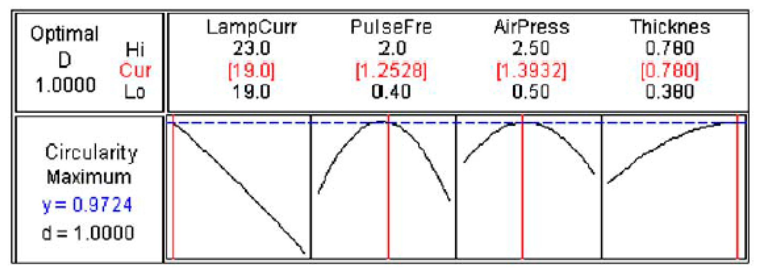
2.4.3. Circularity Formation

The circularity at the bottom of the hole decreased nearly proportionately as the lamp current rises for holes drilled in gamma-titanium aluminide plate by pulsed Nd:YAG laser LBM at a constant plate thickness and air pressure of 0.58 mm and 1.5 kg/cm2, respectively [38]. The higher lamp current produces greater thermal energy that vaporises and melts material instantly as shown in Figure 8. This induces disorders in the material removal process and reduces the circularity. It increases initially and subsequently reduces as a parabolic curvature with the rise of frequency of pulse. First, pulse off time (time between two consecutive laser beam incidents) shortens, and energy of beam is reduced when frequency of pulse rises. This induces less agitation and disorder when material is melted and solidified which improves circularity. Afterwards, when frequency of pulse rises, pulse off time becomes shorter which allows lesser time to solidify, induce disorder and agitation in the melted material. This contributes to reduced circularity [38]. At thinner plates, circularity rises progressively as a non-linear curvature, as the lamp current rises. Similarly, circularity reduces as the lamp current rises in thicker plates when frequency of pulse and pressure of air were steady at 1.2 kHz and 1.5 kg/cm2, correspondingly. Once more, circularity rises as the thickness reduces at higher lamp current. On the contrary, circularity rises as the thickness rises at low lamp currents. Higher lamp current produces larger thermal energy. The entire thickness of workpiece material vaporised and melted immediately which gives a larger hole circularity with rising lamp current when the workpiece thickness is low. For thicker workpiece, the surface at the top vaporised and melted, and it was removed by the pressurised air focusing on the top surface. The removal rate of material reduces and re-solidification might occur at the exit of the hole as workpiece thickness rises, which gives lesser circularity at the exit [38].

2.4.4. Surface Roughness

It was already mentioned that LBM generates different features on machined titanium surface. The severity of the features depends on concentration and distribution of laser energy during the machining process. Muthuramalingam et al. [28] reported that lower (Ra = 2.87 μm) surface roughness is attainable at 2 Kw power, 0.7 mm nozzle distance, −1 mm focal length, and 4 bar of gas pressure for LBM of Ti-alloy. This medium power, lower nozzle distance and higher gas pressure contribute to moderate heat influx and cleanliness of surface, and generate cleaner surface with lower roughness. On the other hand, higher surface roughness (Ra = 21.7 μm) was obtained at power 3 kw, nozzle distance 1.5 mm, focal length −1 mm, and gas pressure of 2 bar. The higher laser power, greater nozzle distance, and lower gas pressure provide low laser energy, temperature, and cleanliness which contribute to higher surface roughness. Ahmed et al. [34] reported that lower current intensity (75–80%) offers good surface roughness (Ra ~ 1.25 μm) at all the levels of scanning speed during laser milling. The pulse frequency of 15 kHz provided the lowest surface finish (Ra ~ 1.15 μm) at the considered levels of scanning speed. The roughness is minimum (Ra ~ 1.05 μm) at scanning speed of 300 mm/s and track displacement of 10 µm regardless of the variations of other variables. The surface finish is more favoured at 2 μm layer thickness [34].

2.4.5. Effect of Scanning Speed

Higher scanning speed means less time for the laser beam to heat up the material and consequently causes lower material removal rate. The density of laser beam energy is inversely proportional to the speed of laser cutting which controls surface integrity in terms of HAZ, hardness, and residual stress [33]. Ahmed et al. [34] reported that regardless of scanning speed, the reduced pulse frequency reduces the percent material removal rate and the 8 μm track displacement gives a higher rate of material removal compared to that of 10 and 12 μm track displacements during laser milling.

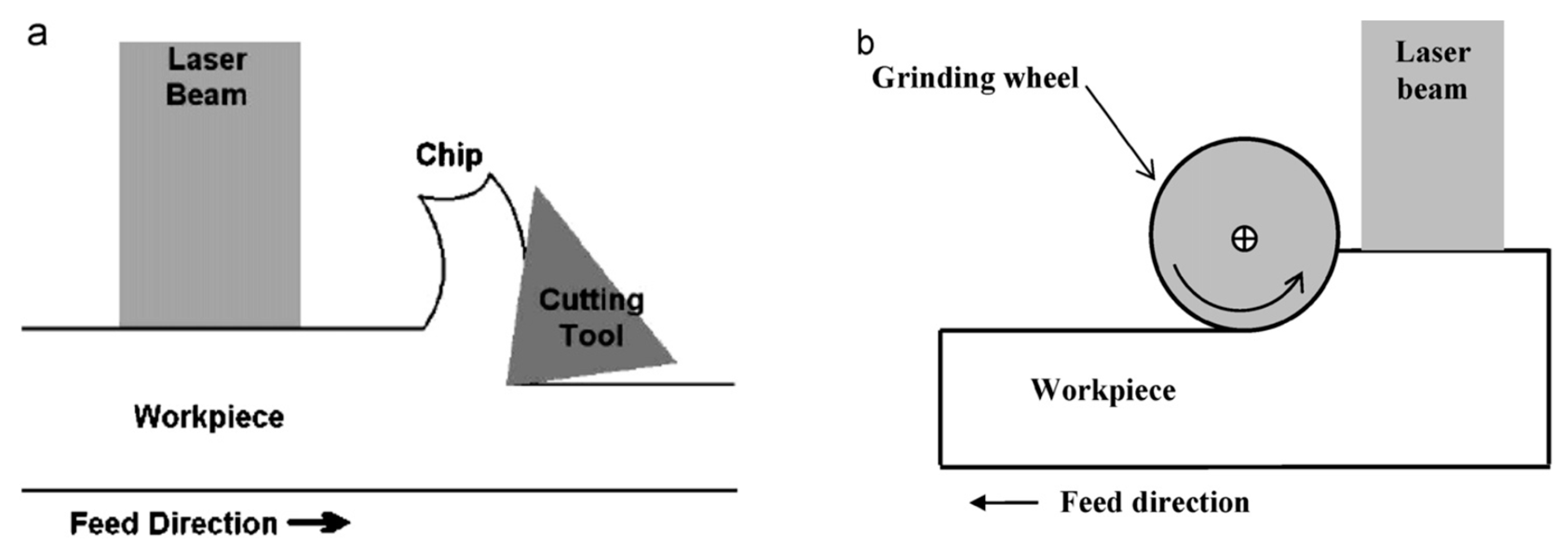
3. Laser Beam-Assisted Hybrid Machining

Material removal rate for a given material, where more than one technique is combined, increases greatly for the machining of sophisticated materials. These procedures are formed to utilise the prospective advantages and to curb the drawbacks accompanying a particular single procedure as indicated in Figure 9 schematically. Generally, the effectiveness of the hybrid procedure is superior to the aggregate performance, when identical variables are utilised. In such procedures, irrespective of the benefits of individual module, a supplementary input might also arrive from the collaboration of the constituent procedures [49]. Nearly all hybrid machining procedures have been established through the combination of traditional or non-traditional machining procedures.
Some of the attempts to combine LBM with other machining processes have become very successful. The energy (thermal) of laser beam was exploited to make workpiece material softer when it is amalgamated with traditional machining procedures, for instance, turning, shaping, and grinding. In laser-aided turning (Figure 9), the laser beam is directed on the workpiece straight before the cutting tool. Laser heating makes the surface layer of difficult-to-machine materials softer. This facilitates ductile deformation instead of brittle deformation while machining. This gives greater material removal rates (MRRs), reduced tool wear, better surface quality, and improved accuracy. It also significantly lowers the cost by dropping machine and man times for each part [50]. Hybridisation of LBM and non-traditional machining procedures is also beneficial for increasing the machining efficiency. Laser-aided etching, laser-aided electro-discharge machining, laser-aided electrochemical machining, and ultrasonic-aided LBM are examples of laser hybrid machining processes.
Yue et al. [51] reported producing deeper holes with reduced recast layer in ultrasonic-aided laser drilling in comparison in the absence of ultrasonication. In laser-aided electrochemical machining, the radiation of laser speeds up the electrochemical reactions and confines the machining into a few microns area which facilitates the improved efficiency and accuracy [52]. Li and Achara [53] noted that chemical-aided (salt solution) machining by laser substantially decreases the recast layer and heat-affected zone along with greater MRR when compared to that of in-air machining by laser beam. Li et al. [54] used LBM and EDM in sequence to produce micro-hole in fuel injecting nozzle. This hybrid methodology eradicated the heat-affected zones and recast layer usually generated in laser drilling which is a kind of nanostructured composite [55,56] as it contains the elements from the base material along with surrounding medium. This hybrid procedure reduced drilling time by 70% compared to that by EDM drilling alone. A laser beam combined with chemical or electro-chemical etching procedures facilitate discerning material removal during local etching [57].

4. Discussions

The leading advantage of the LBM procedure is its potential to machine nearly all classes of materials compared to other broadly employed machining techniques such as USM, ECM, and EDM. If compared with jet machining procedures, it is appropriate for machining smaller and thinner material at higher speed and suitable to machine tiny parts contrasting jet machining procedures, for instance, abrasive water and water jet techniques. Although LBM is a non-contact style non-traditional approach with superior flexibility, the thermal nature of the procedure needs sensitive management of the laser beam to prevent any unsought thermal impact. Among distinctive differences, only cutting and drilling by laser beam were employed broadly whilst 3-D LBM procedures have yet to be advanced and plenty of exploration is necessary beforehand to apply them in industrial applications. This non-traditional technique is also employed in traditional machining of difficult-to-machine materials. The laser-aided hybrid machining procedures are better than a solo non-traditional machining method in numerous uses.
Compared to conventional machining, the striking difference of the non-conventional machining process is that there is no need for any cutting tools to remove materials. Furthermore, the absence of interaction of cutting tools with the materials also causes the absence of shear deformation of material—the primary material deformation mechanisms during conventional machining [58]. Thus, the whole scenario is different in non-conventional machining compared to conventional machining both in terms of physical as well as the material removal mechanism point of view. For example, during EDM, electrical current flow though the workpiece and fast flow of electrolyte flushes the molten/semi-molten materials during the process. Electrical energy converted into heat energy and applied to a small portion of the workpiece fused and/or vaporised the local site. In jet-type machining, erosion is attained by the impact from a high-speed fluid stream or abrasives or amalgamation of both. In addition to that, if the process involves any specific chemical, then preferential chemical etching takes place and removal of materials from a designated zone of the workpiece happens, whereas the rest of the area is sheltered under a cover. Thus, residual stress and chatter problems after machining can be overcome [59].
It is well known that heating-based non-traditional machining processes are not affected by the hardness, strength, and strain hardening of the materials. However, the performance of this machining process is mainly controlled by thermal behaviours of the materials, for instance, thermal conductivity, phase transfer temperature, and melting temperature of materials. Qualitatively, all metallic materials experience recast layer, cracks, craters, globules, diffusion of other materials, and thus alter the machined surface compared to that of bulk material properties [60] and it varies from material to material depending on their respective thermal and electrical properties [61]. The eminent properties of titanium, for example, lower thermal conductivity, higher melting point, and greater strength clearly affect the mechanism of non-traditional machining. The mechanisms of non-traditional machining procedures of titanium alloys are very similar to that of other materials qualitatively but significantly differ quantitatively.

5. Future Aspects/Direction

Ti-alloy is reasonably expensive and particularly popular in biomedical and aerospace fields because of its remarkably preferred properties. The parts made from this alloy needed to be free from flaws for the mentioned applications which are primarily manufactured by traditional machining procedures. Although there are benefits, for instance, low cost and ease of generating complicated forms compared to those of the traditional procedures, these alter the surface properties negatively with little or no control. Despite massive research in this area, numerous problems are yet to be solved. Advanced processes need to be developed, and the existing methods require a comprehensive understanding to enhance quality of parts and techniques, such as efficiency, sustainability, life expectancy, performance, flexible automation, robustness, etc.
The foremost investigated topics in LBM are reviewed in the preceding sections. The available research focused on laser machining such as micromachining and drilling, but 3-D LBM, such as milling and turning, are yet to be used in industries. It is difficult to manipulate more than one laser beam at diverse orientation concurrently in 3-D LBM technique. Workpiece thickness is another restriction in LBM that can be tackled by increasing the quality of the beam. Presently, LBM is used to cut complex shapes in sheet metallic alloys. With the development of advanced materials, LBM needs to be capable of machining difficult-to-machine materials. This development in LBM is a field of future investigation.
Most of the investigations on LBM studied the influence of different parameters on various output characteristics. A few studies used designs of experiments to correlate input and output parameters. Investigators did not consider several vital variables, for instance, heat conductivity, beam spot diameter, material reflectiveness, and the collaborative influences amongst these variables which would influence the outcomes in a different way. Therefore, theoretical models are required to be developed to obtain the predictive capacity of the LBM difficulties quantitatively. The LBM outputs examined by investigators are associated with geometry, metallurgy, and surface characteristics, for instance, surface finish, amount of taper, and HAZ. Residual stresses, micro-hardness and fatigue performance are also vital performance parameters that are necessary to consider. Several essential investigation fields are required to be identified for the forthcoming activities as presented below:
  • To establish theoretical equations for predicting the performance of LBM of titanium alloys.
  • To evaluate and compare the performance of existing techniques together.
  • To extend the developments of hybrid procedures by combining several approaches so that the disadvantages of discrete procedures can be diminished, and the advantages of the considered techniques are super-positioned to strengthen the performance.

6. Conclusions

The non-traditional machining of Ti-alloy is still in the developing stage, though good progress has been made in several areas. The greatly appealing characteristics of this procedure introduced additional complications. The methods have varied mechanisms to remove materials and perform nicely to the specific applications. However, there are shortcomings even in these methods to regulate the output factors as necessary. The discussion above provides the latest developments of LBM and guidance for future investigations. After the above analysis, it can be summarised as follows:
  • LBM is a compelling machining approach for producing complicated shapes and holes in various materials. Nevertheless, the major drawbacks are (a) the lower energy efficacy and (b) diverging/converging profile of the beam.
  • This method is also appropriate for accurate production of miniature parts. The miniature holes of smaller radius (up to 2.5 mm) and higher aspect ratio (above 20) are possible to produce precisely, utilizing tripled lasers of nanosecond frequency.
  • The quality of LBM is controlled by (a) mode of operation, wavelength, and laser power, (b) material thickness and type, and (c) speed, position of focal plane, energy, frequency, pulse interval, aided gas type, and pressure. The output qualities of concern for LBM are hole or kerf taper, HAZ, recast layer, surface finish, dross, and cracks.
  • The investigators optimised the procedure through experimental and statistical optimisation. It is necessary to develop the modelling procedures to identify optimum or close to optimum procedure variables.
  • Substantial investigation is required in the two utmost application fields, for instance, machining of micro-parts and machining thick workpieces.

Author Contributions

A.K.B. and A.P.: Principal investigator, conceptualisation, supervision, review, and editing. All authors have read and agreed to the published version of the manuscript.

Funding

This research received no external funding.

Data Availability Statement

The raw data required to reproduce these findings are available from the corresponding author on reasonable request.

Conflicts of Interest

The authors declare that they have no known competing financial/personal interests that could have appeared to influence the work reported in this paper. There are no conflicts of interest in any form.

References

  1. Dubey, A.K.; Yadava, V. Laser beam machining—A review. Int. J. Mach. Tools Manuf. 2008, 48, 609–628. [Google Scholar] [CrossRef]
  2. Biffi, C.A.; Lecis, N.; Previtali, B.; Vedani, M.; Vimercati, G.M. Fiber laser microdrilling of titanium and its effect on material microstructure. Int. J. Adv. Manuf. Technol. 2011, 54, 149–160. [Google Scholar] [CrossRef]
  3. Donachie, M.J. Titanium: A Technical Guide; ASM International, Materials Park: Novelty, OH, USA, 2000. [Google Scholar]
  4. Arisoy, Y.M.; Özel, T. Machine learning based predictive modeling of machining induced microhardness and grain size in Ti–6Al–4V alloy. Mater. Manuf. Process. 2015, 30, 425–433. [Google Scholar] [CrossRef]
  5. Kalantari, O.; Fallah, M.; Jafarian, F.; Hamzeloo, S. Surface integrity in laser-assisted machining of Ti6Al4V. Proc. Inst. Mech. Eng. Part C J. Mech. Eng. Sci. 2021, 235, 5009–5016. [Google Scholar] [CrossRef]
  6. Blog, E. Machinability Rating and Chart. Available online: https://blog.enerpac.com/machinability-rating-and-chart-download/ (accessed on 10 August 2023).
  7. Pandey, A.K.; Dubey, A.K. Simultaneous optimization of multiple quality characteristics in laser cutting of titanium alloy sheet. Opt. Laser Technol. 2012, 44, 1858–1865. [Google Scholar] [CrossRef]
  8. Kumar, J. Investigating the Machining Characteristics of Titanium Using Ultrasonic Machining. Ph.D. Thesis, Thapar Institute of Engineering Technology, Patiala, India, 2009. [Google Scholar]
  9. Kara, F.; Takmaz, A. Optimization of cryogenic treatment effects on the surface roughness of cutting tools. Mater. Test. 2019, 61, 1101–1104. [Google Scholar] [CrossRef]
  10. Plastike, M.O.J.Z.B. Optimization of surface roughness in finish milling of AISI P20+ S plastic-mold steel. Optimization 2018, 195, 200. [Google Scholar]
  11. Kara, F.; Karabatak, M.; Ayyıldız, M.; Nas, E. Effect of machinability, microstructure and hardness of deep cryogenic treatment in hard turning of AISI D2 steel with ceramic cutting. J. Mater. Res. Technol. 2020, 9, 969–983. [Google Scholar] [CrossRef]
  12. Pramanik, A.; Basak, A.; Prakash, C. Understanding the wire electrical discharge machining of Ti6Al4V alloy. Heliyon 2019, 5, e01473. [Google Scholar] [CrossRef]
  13. Basak, A.; Pramanik, A.; Prakash, C. Surface, kerf width and material removal rate of Ti6Al4V titanium alloy generated by wire electrical discharge machining. Heliyon 2019, 5, 01473. [Google Scholar]
  14. Basak, A.; Pramanik, A.; Prakash, C.; Kotecha, K. Micro-mechanical characterization of superficial layer synthesized by electric discharge machining process. Mater. Lett. 2021, 305, 130769. [Google Scholar] [CrossRef]
  15. Pramanik, D.; Kuar, A.; Sarkar, S.; Mitra, S. Enhancement of sawing strategy of multiple surface quality characteristics in low power fiber laser micro cutting process on titanium alloy sheet. Opt. Laser Technol. 2020, 122, 105847. [Google Scholar] [CrossRef]
  16. Pramanik, A. Problems and solutions in machining of titanium alloys. Int. J. Adv. Manuf. Technol. 2014, 70, 919–928. [Google Scholar] [CrossRef]
  17. Müller, F.; Monaghan, J. Non-conventional machining of particle reinforced metal matrix composite. Int. J. Mach. Tools Manuf. 2000, 40, 1351–1366. [Google Scholar] [CrossRef]
  18. Bandyopadhyay, S.; Gokhale, H.; Sundar, J.S.; Sundararajan, G.; Joshi, S. A statistical approach to determine process parameter impact in Nd: YAG laser drilling of IN718 and Ti-6Al-4V sheets. Opt. Lasers Eng. 2005, 43, 163–182. [Google Scholar] [CrossRef]
  19. Bandyopadhyay, S.; Sundar, J.S.; Sundararajan, G.; Joshi, S. Geometrical features and metallurgical characteristics of Nd: YAG laser drilled holes in thick IN718 and Ti–6Al–4V sheets. J. Mater. Process. Technol. 2002, 127, 83–95. [Google Scholar] [CrossRef]
  20. Tabata, N.; Yagi, S.; Hishii, M. Present and future of lasers for fine cutting of metal plate. J. Mater. Process. Technol. 1996, 62, 309–314. [Google Scholar] [CrossRef]
  21. Biswas, R.; Kuar, A.; Mitra, S. Multi-objective optimization of hole characteristics during pulsed Nd: YAG laser microdrilling of gamma-titanium aluminide alloy sheet. Opt. Lasers Eng. 2014, 60, 1–11. [Google Scholar] [CrossRef]
  22. Meijer, J. Laser beam machining (LBM), state of the art and new opportunities. J. Mater. Process. Technol. 2004, 149, 2–17. [Google Scholar] [CrossRef]
  23. Steen, W.M.; Mazumder, J. Laser Material Processing; Springer Science & Business Media: Berlin/Heidelberg, Germany, 2010. [Google Scholar]
  24. Hong, L.; Vilar, R.; Youming, W. Laser beam processing of a SiC particulate reinforced 6061 aluminium metal matrix composite. J. Mater. Sci. 1997, 32, 5545–5550. [Google Scholar] [CrossRef]
  25. Chryssolouris, G. Laser Machining: Theory and Practice; Springer Science & Business Media: Berlin/Heidelberg, Germany, 2013. [Google Scholar]
  26. Pham, D.; Dimov, S.; Petkov, P. Laser milling of ceramic components. Int. J. Mach. Tools Manuf. 2007, 47, 618–626. [Google Scholar] [CrossRef]
  27. Muthuramalingam, T.; Moiduddin, K.; Akash, R.; Krishnan, S.; Mian, S.H.; Ameen, W.; Alkhalefah, H. Influence of process parameters on dimensional accuracy of machined Titanium (Ti-6Al-4V) alloy in Laser Beam Machining Process. Opt. Laser Technol. 2020, 132, 106494. [Google Scholar] [CrossRef]
  28. Muthuramalingam, T.; Akash, R.; Krishnan, S.; Phan, N.H.; Pi, V.N.; Elsheikh, A.H. Surface quality measures analysis and optimization on machining titanium alloy using CO2 based laser beam drilling process. J. Manuf. Process. 2021, 62, 1–6. [Google Scholar] [CrossRef]
  29. Sahu, A.K.; Jha, S. Microchannel fabrication and metallurgical characterization on titanium by nanosecond fiber laser micromilling. Mater. Manuf. Process. 2020, 35, 279–290. [Google Scholar] [CrossRef]
  30. Worts, N.; Jones, J.; Squier, J. Surface structure modification of additively manufactured titanium components via femtosecond laser micromachining. Opt. Commun. 2019, 430, 352–357. [Google Scholar] [CrossRef]
  31. Obeidi, M.A.; Mussatto, A.; Dogu, M.N.; Sreenilayam, S.P.; McCarthy, E.; Ahad, I.U.; Keaveney, S.; Brabazon, D. Laser surface polishing of Ti-6Al-4V parts manufactured by laser powder bed fusion. Surf. Coat. Technol. 2022, 434, 128179. [Google Scholar] [CrossRef]
  32. Lee, S.; Ahmadi, Z.; Pegues, J.W.; Mahjouri-Samani, M.; Shamsaei, N. Laser polishing for improving fatigue performance of additive manufactured Ti-6Al-4V parts. Opt. Laser Technol. 2021, 134, 106639. [Google Scholar] [CrossRef]
  33. Shanjin, L.; Yang, W. An investigation of pulsed laser cutting of titanium alloy sheet. Opt. Lasers Eng. 2006, 44, 1067–1077. [Google Scholar] [CrossRef]
  34. Ahmed, N.; Ahmad, S.; Anwar, S.; Hussain, A.; Rafaqat, M.; Zaindin, M. Machinability of titanium alloy through laser machining: Material removal and surface roughness analysis. Int. J. Adv. Manuf. Technol. 2019, 105, 3303–3323. [Google Scholar] [CrossRef]
  35. Almeida, I.; De Rossi, W.; Lima, M.; Berretta, J.; Nogueira, G.; Wetter, N.; Vieira, N., Jr. Optimization of titanium cutting by factorial analysis of the pulsed Nd: YAG laser parameters. J. Mater. Process. Technol. 2006, 179, 105–110. [Google Scholar] [CrossRef]
  36. Goyal, R.; Dubey, A.K. Hybrid approach for modeling and optimization of hole taper during laser trepan drilling of Ti-6Al-4V alloy sheet. Procedia Mater. Sci. 2014, 5, 1781–1790. [Google Scholar] [CrossRef]
  37. Ng, G.; Li, L. The effect of laser peak power and pulse width on the hole geometry repeatability in laser percussion drilling. Opt. Laser Technol. 2001, 33, 393–402. [Google Scholar] [CrossRef]
  38. Biswas, R.; Kuar, A.; Sarkar, S.; Mitra, S. A parametric study of pulsed Nd: YAG laser micro-drilling of gamma-titanium aluminide. Opt. Laser Technol. 2010, 42, 23–31. [Google Scholar] [CrossRef]
  39. Ghany, K.A.; Newishy, M. Cutting of 1.2 mm thick austenitic stainless steel sheet using pulsed and CW Nd: YAG laser. J. Mater. Process. Technol. 2005, 168, 438–447. [Google Scholar] [CrossRef]
  40. Chen, S.-L. The effects of high-pressure assistant-gas flow on high-power CO2 laser cutting. J. Mater. Process. Technol. 1999, 88, 57–66. [Google Scholar] [CrossRef]
  41. Lamikiz, A.; de Lacalle, L.L.; Sanchez, J.; Del Pozo, D.; Etayo, J.; Lopez, J. CO2 laser cutting of advanced high strength steels (AHSS). Appl. Surf. Sci. 2005, 242, 362–368. [Google Scholar] [CrossRef]
  42. Rajaram, N.; Sheikh-Ahmad, J.; Cheraghi, S. CO2 laser cut quality of 4130 steel. Int. J. Mach. Tools Manuf. 2003, 43, 351–358. [Google Scholar] [CrossRef]
  43. Duley, W.; Gonsalves, J. CO2 laser cutting of thin metal sheets with gas jet assist. Opt. Laser Technol. 1974, 6, 78–81. [Google Scholar] [CrossRef]
  44. Zheng, H.; Han, Z.; Chen, Z.; Chen, W.; Yeo, S. Quality and cost comparisons between laser and waterjet cutting. J. Mater. Process. Technol. 1996, 62, 294–298. [Google Scholar] [CrossRef]
  45. Al-Sulaiman, F.; Yilbas, B.; Ahsan, M. CO2 laser cutting of a carbon/carbon multi-lamelled plain-weave structure. J. Mater. Process. Technol. 2006, 173, 345–351. [Google Scholar] [CrossRef]
  46. Lum, K.; Ng, S.; Black, I. CO2 laser cutting of MDF: 1. Determination of process parameter settings. Opt. Laser Technol. 2000, 32, 67–76. [Google Scholar] [CrossRef]
  47. Karatas, C.; Keles, O.; Uslan, I.; Usta, Y. Laser cutting of steel sheets: Influence of workpiece thickness and beam waist position on kerf size and stria formation. J. Mater. Process. Technol. 2006, 172, 22–29. [Google Scholar] [CrossRef]
  48. Illyefalvi-Vitez, Z. Laser processing of adhesives and polymeric materials for microelectronics packaging applications. In Proceedings of the 4th International Conference on Adhesive Joining and Coating Technology in Electronics Manufacturing, Espoo, Finland, 6 August 2002; Presented at Adhesives in Electronics 2000 (Cat. No. 00EX431). pp. 289–295. [Google Scholar]
  49. Yadava, V.; Jain, V.K.; Dixit, P.M. Temperature distribution during electro-discharge abrasive grinding. Mach. Sci. Technol. 2002, 6, 97–127. [Google Scholar] [CrossRef]
  50. Rozzi, J.C.; Pfefferkorn, F.E.; Incropera, F.P.; Shin, Y.C. Experimental evaluation of the laser assisted machining of silicon nitride ceramics. In ASME International Mechanical Engineering Congress and Exposition; American Society of Mechanical Engineers: New York, NY, USA, 2000; pp. 229–239. [Google Scholar]
  51. Yue, T.M.; Chan, T.; Man, H.C.; Lau, W. Analysis of ultrasonic-aided laser drilling using finite element method. CIRP Ann. 1996, 45, 169–172. [Google Scholar] [CrossRef]
  52. Rajurkar, K.; Levy, G.; Malshe, A.; Sundaram, M.; McGeough, J.; Hu, X.; Resnick, R.; DeSilva, A. Micro and nano machining by electro-physical and chemical processes. CIRP Ann. 2006, 55, 643–666. [Google Scholar] [CrossRef]
  53. Li, L.; Achara, C. Chemical assisted laser machining for the minimisation of recast and heat affected zone. CIRP Ann. 2004, 53, 175–178. [Google Scholar] [CrossRef]
  54. Li, L.; Diver, C.; Atkinson, J.; Giedl-Wagner, R.; Helml, H. Sequential laser and EDM micro-drilling for next generation fuel injection nozzle manufacture. CIRP Ann. 2006, 55, 179–182. [Google Scholar] [CrossRef]
  55. Basak, A.; Matteazzi, P.; Vardavoulias, M.; Celis, J.-P. Corrosion–wear behaviour of thermal sprayed nanostructured FeCu/WC–Co coatings. Wear 2006, 261, 1042–1050. [Google Scholar] [CrossRef]
  56. Basak, A.K.; Celis, J.-P.; Vardavoulias, M.; Matteazzi, P. Effect of nanostructuring and Al alloying on friction and wear behaviour of thermal sprayed WC–Co coatings. Surf. Coat. Technol. 2012, 206, 3508–3516. [Google Scholar] [CrossRef]
  57. Stephen, A.; Sepold, G.; Metev, S.; Vollertsen, F. Laser-induced liquid-phase jet-chemical etching of metals. J. Mater. Process. Technol. 2004, 149, 536–540. [Google Scholar] [CrossRef]
  58. Mandal, A.; Dixit, A.R.; Chattopadhyaya, S.; Paramanik, A.; Hloch, S.; Królczyk, G. Improvement of surface integrity of Nimonic C 263 super alloy produced by WEDM through various post-processing techniques. Int. J. Adv. Manuf. Technol. 2017, 93, 433–443. [Google Scholar] [CrossRef]
  59. Wang, F.; Liu, Y.; Zhang, Y.; Tang, Z.; Ji, R.; Zheng, C. Compound machining of titanium alloy by super high speed EDM milling and arc machining. J. Mater. Process. Technol. 2014, 214, 531–538. [Google Scholar] [CrossRef]
  60. Alshemary, A.; Pramanik, A.; Basak, A.; Littlefair, G. Accuracy of duplex stainless steel feature generated by electrical discharge machining (EDM). Measurement 2018, 130, 137–144. [Google Scholar] [CrossRef]
  61. Moses, M.-D.; Jahan, M. Micro-EDM machinability of difficult-to-cut Ti-6Al-4V against soft brass. Int. J. Adv. Manuf. Technol. 2015, 81, 1345–1361. [Google Scholar] [CrossRef]
Figure 1. Schematic of a beam profile in laser beam machining applications [1].
Metals 13 01536 g001
Figure 2. Schematic of Nd:YAG laser beam machining system [1].
Metals 13 01536 g002
Figure 3. SEM micrograph of representative laser cut: (a) kerf with HAZ, and (b) metastable acicular martensite in HAZ region [33] during argon-assisted Nd:YAG LBM (2 J; 25 Hz; 1 mm/s; 0.6 MPa).
Metals 13 01536 g003
Figure 4. Cross-section morphology of surface generated from argon-assisted LBM (1 mm/s; 25 Hz; 2.0 J) [33].
Metals 13 01536 g004
Figure 5. Surface generated by LBM: (a) argon-assisted, (b) air-assisted, and (c) nitrogen-assisted (1 mm/s; 25 Hz; 2.0 J) [33].
Metals 13 01536 g005
Figure 6. Effect of (a) pulse energy, (b) speed, and (c) pressure of gas on the thickness of HAZ during LBM using Nd:YAG pulsed laser [33].
Metals 13 01536 g006
Figure 7. Optimisation results of minimum hole taper [21]. The curved lines show the trend of the associated parameters.
Metals 13 01536 g007
Figure 8. Optimised parameters for highest circularity at the exit of hole [21]. The curved lines show the trend of the associated parameters.
Metals 13 01536 g008
Figure 9. Graphical presentation of (a) laser-aided turning and (b) laser-aided grinding [1].
Metals 13 01536 g009
Table 1. Rating of machinability of some common materials including titanium alloys [8].
MaterialsTreatment ConditionsMachinability
Aluminum AlloySolution treated and aged300
Re-sulfurized Steel (B1112)Hot rolled100
Carbon steel (1020)Cold drawn70
Alloy steel (4340)Annealed45
Titanium (pure)Annealed40
Stainless steel (302)Annealed35
Titanium alloy (Grade 6)Annealed30
Titanium alloy (Grade 5)Annealed22
Titanium alloy (Ti-6-6-2)Annealed20
Titanium alloy (Grade 5)Solution treated and aged18
Co-based alloys (HS25)Annealed10
Ni-based alloys (Rene 41)Solution treated and aged6
Disclaimer/Publisher’s Note: The statements, opinions and data contained in all publications are solely those of the individual author(s) and contributor(s) and not of MDPI and/or the editor(s). MDPI and/or the editor(s) disclaim responsibility for any injury to people or property resulting from any ideas, methods, instructions or products referred to in the content.

