Article

Ratcheting–Fatigue Damage Assessment of Additively Manufactured SS304L and AlSi10Mg Samples under Asymmetric Stress Cycles

1
Department of Mechanical and Industrial Engineering, Toronto Metropolitan University, 350 Victoria Street, Toronto, ON M5B 2K3, Canada
2
Department of Aerospace Engineering, Toronto Metropolitan University, 350 Victoria Street, Toronto, ON M5B 2K3, Canada
*
Author to whom correspondence should be addressed.
Metals 2023, 13(9), 1534; https://doi.org/10.3390/met13091534
Submission received: 4 August 2023 / Revised: 26 August 2023 / Accepted: 28 August 2023 / Published: 30 August 2023

Abstract

:
The present study aims to investigate the interaction of ratcheting and fatigue phenomena for additively manufactured (AM) samples of SS304L and AlSi10Mg undergoing uniaxial asymmetric stress cycles. Overall damage was accumulated through fatigue and ratcheting on AM samples prepared from three-dimensional-printed plates along vertical and horizontal directions. Fatigue damage was evaluated based on the strain energy density fatigue approach and ratcheting damage was calculated through use of an isotropic–kinematic hardening framework. The isotropic description through the Lee–Zavrel (L–Z) model formed the initial and concentric expansion of yield surfaces while the Ahmadzadeh–Varvani (A–V) kinematic hardening rule translated yield surfaces into the deviatoric stress space. Ratcheting of AM samples was simulated using finite element analysis through use of triangular and quadrilateral elements. Ratcheting values of the AM samples were simulated on the basis of Chaboche’s materials model. The predicted and simulated ratcheting damage curves placed above the experimental fatigue–ratcheting experimental data while predicted fatigue damage curves collapsed below the measured values. The overall damage was formulated to partition damage weights due to fatigue and ratcheting phenomena.

1. Introduction

Additive manufacturing (AM) techniques, as compared to conventional manufacturing methods, offer ease of fabricating complex geometries and diversity in materials characteristics. Three-dimensional-printed AM samples are vastly employed in construction, aerospace, medical science, electronic, and transportation industries to optimize production lead time, operational costs, and lightweight parts. AM techniques are reported to be more environmentally sound as compared with conventional methods [1,2,3]. Over the last two decades, more of intension has been focused to improve the load-bearing capability of AM machinery components and structures. Layer-by-layer construction in these components, method of additive manufacturing, speed of processing and residual stresses induced within layers, as well as surface roughness and pores formed during heat transfer were noted as challenges in AM metallic parts undergoing severe loading conditions [4,5,6].
Selective laser manufactured AlSi10Mg samples demonstrated a 40% reduction in rotating bending fatigue strength compared to conventional material [7]. Surface porosity largely explained this reduction, while surface roughness of additively manufactured AlSi10Mg specimens was four times greater than that of conventional material. According to Siddique et al. [8], sub-surface pores combined with surface roughness play a major role in crack nucleation and fatigue strength reduction for AlSi10Mg specimens. To increase the fatigue performance of fatigue-loaded components, Avanzini et al. [9] studied the fatigue behavior of AlSi10Mg samples produced with DMLS and sandblasted. In comparison with other surface treatments, they found SB to be a positive process for fatigue properties. Aboulkhair et al. [10] recommended remelting contour zones as a scan strategy. They reported the existence of un-melted particles and the gas porosity as the reasons for the pores in AlSi10Mg samples and, to minimize the appearance of pores, they suggested a slower scanning speed.
Fatigue behavior of AM Ti-6Al-4V under uniaxial cyclic loading for different manufacturing processes of E-beam powder bed fusion (E-PBF), L-PBF, and wired-feed directed energy deposition (DED) was studied by Li et al. [11]. They reported internal defects, surface roughness, and residual stresses as the main factors that influenced the fatigue behavior of AM materials. The level of ductility of AM materials determined the impact of these factors on the fatigue response. Depending on the process of manufacturing, the effect of surface roughness of ∼200 µm on the fatigue strength of AM Ti-6Al-4V was found to be detrimental by 20–25% [12]. Additively manufactured samples consist of smaller dendritic grains which offer greater hardness as compared to conventionally fabricated components. Jeyaprakash et al. [13] investigated mechanical characteristics of additively and conventionally casted manufactured SS304 samples and evidenced that AM samples achieved higher strength as a result of precipitation strengthening and grain refinement. Shrestha et al. [14] studied the impact of fabrication orientation on fatigue properties of high- and low-cycle regimes for as-built and polished surfaces of LB-PBF 316L stainless steel. They revealed that, despite the desirable fatigue properties achieved under all conditions, cyclic behavior depended more on build orientations in high-cycle fatigue. Samples with horizontal directions established with respect to the loading path demonstrated better fatigue resistance, while diagonal samples possessed the lowest resistance. Zhang et al. [15] investigated the influence of different process parameters on fatigue behavior of AM SS316L in the horizontal direction. They found that employing optimal process parameters through fabrication resulted in cracks formation from microstructural levels. It revealed to be within a ±30% tolerance band, which is a safe processing region, as high-cycle fatigue properties are independent of crack initiation from microstructural features. Beyond the designated region of processing, the cracks created by over-melting and under-melting led to a drop in fatigue resistance. Defects initiated closer to the surface exposed to large local stresses and caused them to have greater impacts on fatigue resistance [16]. Hot isostatic pressing (HIP) post-processing technique was employed to lessen pores and defects in AM samples at high temperatures. Leuders et al. [17] employed an HIP process and treated the AM samples made of Ti-6Al-4V under pressure of 14.5 ksi at 920 °C for 2 h. They reported that titanium samples achieved a higher ductility and fatigue limit as compared with their counterpart conventional material [17]. HIP-processed AM samples of Ti-6Al-4V were surface-machined and their fatigue behavior was tested by Molaei et al. [18]. They reported that as-built HIP samples with no surface-machining process demonstrated considerably smaller fatigue lives as compared with those of surfacefinished [18]. In addition to the AM technique, technical issues including specimen direction, speed of manufacturing, post-processing treatment, and the loading spectrum can accelerate the process of damage and failure in AM samples. Some researchers studied the influence of ratcheting strain on mechanical properties of AM materials [19,20]. Wang et al. [19] and Dong et al. [20] performed cyclic tests on AM samples made of Al 4043 alloy with various stress ratios to study the ratcheting response of materials at different stress levels. AM aluminum samples possessed a higher tensile yield strength, while the materials’ elongation was reduced. The effect of heat treatment on the cyclic behavior of AM specimens was investigated by Ghosh et al. [21] and Servatan et al. [22]. According to Ghosh et al. [21], as-built additively manufactured samples showed a 50% lower fatigue life when compared with heat-treated samples. Servatan et al. [22] demonstrated that the initial and translated yield surfaces of the heat-treated AM Ti–6Al–4V sample were modified due to the impact of the thermal process on material properties. When heat-treated titanium samples were compared to their as-built counterparts, heat treatment suppressed yield magnitude and promoted ratcheting strain twice as much. Zang et al. [23] explored the impact of different building orientations on the ratcheting response of AM 316L stainless steel samples. They found that the ratcheting rate of vertical specimens is slower than horizontal AM samples in the same loading condition. The ratcheting behavior of various AM materials of Al 4043, SS316L, and Ti–6Al–4V alloy was examined through the use of a combined isotropic–kinematic hardening rules and finite element method (FEM) [22,24]. The Chaboche hardening rule employed in the FEM model demonstrated ratcheting results with a deviation of less than 10% with predicted results achieved by the combined framework.
Several studies were conducted on the damage evaluation of conventional wrought metallic materials [25,26,27]. They demonstrated that an excess of damage generated due to the ratcheting phenomenon over asymmetric loading cycles noticeably reduced the fatigue life of conventional materials. The concurrent fatigue–ratcheting damage of ASTM A-516 Gr.70 and 42CrMo samples was modelled in a recent study by Ahmadzadeh and Varvani [28]. They defined overall damage through phenomenological parameters involving stress amplitude, mean stress, and cyclic softening/hardening terms integrating damages due to ratcheting and fatigue. By combining the CDM theory and ML models, Zhan et al. [29] proposed a new method for predicting the fatigue life of AM aerospace alloys. As well as the predicted accuracy of fatigue life, the performance of ANN and RF models was also discussed. The predicted results were verified and almost all fell within the three-error band when compared to experimental results. They concluded that it is appropriate to employ this approach based on elastoplastic fatigue damage and ML models for predicting life. As the literature lacks the cyclic plasticity and ratcheting assessment of AM materials, the present study intends to implement an earlier developed damage model [28] to define overall damage due to the ratcheting–fatigue interaction in AM SS304L and AlSi10Mg samples. An isotropic–kinematic hardening framework was employed along a fatigue damage approach to evaluate ratcheting and fatigue damages, respectively. Simulated ratcheting damage curves were determined through finite element analysis and based on Chaboche’s materials model. The predicted and simulated fatigue and ratcheting damage curves were defined as, respectively, lower and upper curves with respect to experimental values. Partitioning overall damage to fatigue and ratcheting curves makes it possible to control influential variables and design durable components undergoing severe loading spectra.

2. Materials and Methods

2.1. Fatigue Damage Assessment

Fatigue damage was evaluated through use of an energy-based critical plane approach developed earlier by Varvani–Farahani [30]. Stress and strain components in the damage model were defined on the most damaging plane at which both stress and strain Mohr’s circles were largest during loading and unloading reversals. The normal energy was defined from the product of normal stress and strain ranges acting on the critical plane and the shear energy was calculated from shear stress and shear strain ranges acting on the critical plane. The general form of fatigue damage approach is expressed by Equation (1). Both normal and shear energy components in the left-hand side of this equation are normalized by the product of fatigue strength and ductility coefficients to achieve a unitless damage and weight the contribution of normal and shear energies [30].
D f = 1 σ f , ε f ' ( Δ σ n Δ ε n ) + ( 1 + σ n m σ f ' ) ( τ f , γ f ' ) ( Δ τ m a x Δ ( γ m a x 2 ) ) = A . N α + B . N β
Terms Δ τ m a x and Δ ( γ m a x 2 ) correspond to the range of maximum shear stress and shear strain, respectively, which were determined during the first and the second reversals of a cycle from the largest stress and strain Mohr’s circles. The normal stress range and the normal strain range acting on the critical plane are denoted, respectively, by Δ σ n and Δ ε n in the damage model. The right-hand side of Equation (1) is defined by a power law equation as function of number of cycles to failure N and material constants A, α , β , and B.

2.2. Ratcheting Damage Assessment

Ratcheting damage was formulated conforming to fatigue damage equation. Equation (2) describes ratcheting damage through the product of normal stress range Δ σ n and ratcheting strain just before failure ε r f . Ratcheting damage was expressed by Equation (2). The left-hand side of this equation is normalized by fatigue strength and ductility coefficients.
D r = Δ σ n ε r f σ f ' ε f ' = C r + K r . N X
Coefficients C r , K r , and x on the right-hand side of Equation (2) are material-dependent. The range of stress level is shown by Δ σ n = σ m a x for fully reversed loading condition (stress ratio r = −1). The ratcheting strain value at failure ε r f for various asymmetric stress levels was predicted and simulated as an input value in Equation (2).

2.2.1. Isotropic Hardening Description

Karvan and Varvani [31] extensively evaluated various isotropic descriptions and their influential parameters in the ratcheting response of metallic alloys over the first few stress cycles (stage I). They reported that the Lee and Zavrel (L–Z) isotropic model [32] with less complex description and variables offered a closer agreement with experimental data when it was employed along the A–V kinematic hardening rule. The Lee–Zavrel isotropic hardening rule was employed to evaluate the expansion of yield surface and the evolution of concentric yield surfaces was determined through the superposition of initial yield surface, σ y 0 , and isotropic hardening variable R.
σ y = σ y 0 + R ( p )
The isotropic internal variable is defined based on accumulated plastic strain and is shown as:
R = Q ( 1 e b p )
Terms Q and b in Equation (4) are material constants. These constants are determined by the saturated value of variable R and the evolution rate of R obtained through regression of the applied maximum stress plotted versus accumulated plastic strain p. The accumulated plastic strain p increases dramatically over the initial few stress cycles and the exponential term approaches zero. The drag stress R is stabilized at Q. The number of cycles to saturated state of R is dependent on the magnitude of plastic strain.

2.2.2. Ahmadzadeh–Varvani (A–V) Kinematic Hardening Rule

Ahmadzadeh–Varvani (A–V) [33,34] developed a kinematic hardening rule to control yield surface translation in the deviatoric stress space. The A–V model governed the movement of yield surface through increments of backstress. The backstress increments in the hardening rule consist of linear and non-linear terms. Backstress increments controlled the evolution of yield surfaces for loading beyond elastic limit. Beyond the elastic limit, the dynamic recovery term of the A–V rule controls the yield surface translation through its parameters and an internal variable b ¯ . Term ( a ¯ δ b ¯ ) in the dynamic recovery enables a progressive decay and gradual evolution of backstress a ¯ through the loading process. The general form of the A–V model is defined as:
d a ¯ = C d ε ¯ p γ 1 ( a ¯ δ b ¯ ) d p d b ¯ = γ 2 ( a ¯ b ¯ ) d p
In uniaxial loading condition, coefficient δ is expressed as ( a ¯ k ) m , in which constant k is defined as C γ 1 . The exponent m is a material constant and falls between zero and unity. Equation (5) is rewritten as:
d a ¯ = C d ε ¯ p γ 1 ( a ¯ ( a ¯ k ) m b ¯ ) d p
The material-dependent coefficients C and γ 1 are found from uniaxial stress-strain hysteresis loop obtained through a stress-controlled test. Coefficient γ 2 is determined from experimental ratcheting data plotted versus the number of stress cycles.
The increment of equivalent plastic strain, d p , is determined by
d p = 2 3 d ε ¯ P . d ε ¯ P
where the term d ε ¯ P is related to the increment of plastic strain and is expressed as:
d ε ¯ P = 1 H p d s . n ¯ n ¯
The normal vector n ¯ to the yield surface is defined as:
n ¯ = ( s a ¯ ) | ( s a ¯ ) |
In Equation (9), term s denotes the deviatoric stress tensor which corresponds to the amount of loading beyond the elastic domain:
s = σ 1 3 ( σ . I ) I

2.2.3. Chaboche Hardening Rule

Chaboche and co-workers [35] presented a model consisting of three backstress components, α ¯ 1 , α ¯ 2 , and α ¯ 3 , which result from decomposing the nonlinear kinematic hardening rule. Initially, a high modulus of plasticity was defined by α ¯ 1 , while the second and third backstress components, α ¯ 2 and α ¯ 3 , were to control, respectively, the transient part of the hysteresis loop and the linear hardening part of the loop. The Chaboche hardening rule in its general form was defined as:
d α ¯ = i = 1 M d α ¯ i ,   d α ¯ i = 2 3 C i d ε ¯ P γ i ' α ¯ i d p
where C i and γ i ' are the Chaboche material coefficients determined from the strain-controlled hysteresis loop of materials.

2.3. Fatigue–Ratcheting Interaction

The overall damage was determined from the accumulation of fatigue and ratcheting damages. These damage values were weighted through the weighting factor ξ . This factor made it possible to partition damage contributions due to ratcheting and fatigue phenomena. The total damage D t o t a l is composed of fatigue and ratcheting damage and formulated as [28]:
D t o t a l = ξ D f + ( 1 ξ ) D r
where the weighting factor ξ is calculated through interpolation from the upper-bound ratcheting curve ( D r N ) and the lower-bound damage curve ( D f N ) constructed based on fatigue damage at a fully reversed loading condition (R = −1). The measured damage data ( D e x p N ) of the tested samples fall between these bounds. At the given life, the factor ξ is defined as:
ξ = D r D e x p D r D f
The upper ratcheting damage curve is highly influenced by stress level over the asymmetric loading cycles. This elevates the damage weighting factor induced due to the ratcheting phenomenon.
Overall damage due to fatigue–ratcheting is then defined through the integration of lower and upper damage curves defined, respectively, through Equations (1) and (2) and substituting it in Equation (12) as:
Δ σ n ( ε r f + ξ ( Δ ε n ε r f ) ) σ f , ε f ' + ξ ( 1 + σ n m σ f ' ) ( τ f , γ f ' ) ( Δ τ m a x Δ ( γ m a x 2 ) ) = ξ ( A . N α + B . N β ) + ( 1 ξ ) ( C r + K r . N X )

3. Results and Discussion

3.1. Materials, Tests, and Ratcheting Data

Additively manufactured (AM) samples of SS304L [36,37] and AlSi10Mg alloy [38] were cyclically tested at different uniaxial stress levels and non-zero mean stress values. Both AlSi10Mg and SS304L alloys have been used to manufacture load-bearing components in a variety of industries including automotive, aerospace, defense, machinery, and construction [39,40]. The aluminum alloy AlSi10Mg possesses a greater strength and hardness than other aluminum alloys through its silicon and magnesium contents. The SS304L alloy, with 18% chromium and 8% nickel, offers great corrosion resistance and weldability. These alloys offer superior physical and mechanical properties such as excellent corrosion resistance, high ductility, high electrical and thermal conductivity, and great materials for additive manufacturing techniques. AM samples of SS304L were prepared from a 3D baseplate fabricated through gas metal arc welding (GMAW) [36,37]. The layer-by-layer fabrication process was continued along vertical and horizontal printing directions. A few-seconds pause was introduced between two subsequent layers to allow for the cooling process and in order to drop the temperature to 200 °C. The 3D fabrication was operated with a voltage of 22 V, travel speed of 15.24 cm/min, and wire feed of 55.8 cm/min to produce a wall with a total length of 67.31 cm, height of 17.47 cm, and thickness of 6.35 mm. To prepare flat dog-bone fatigue specimens, the wall was machined according to ASTM E466-15. Samples were then divided into horizontal and vertical orientations. AlSi10Mg samples were also additively manufactured through the laser powder bed fusion and BLT-S310 equipment in the form of a 3D block of 110 × 55 × 120 mm [38]. The fabrication process was controlled through a scanning speed of ~1200–1500 mm/s, hatch spacing of ~0.13–0.16 mm, and laser power of ~360–400 W. The thickness and angle of each layer was optimized to be, respectively, 50 μm and 67 ° when scanning the successive layers. The printed block was post-heat-treated at 300 ° C for two hours and was then allowed to naturally age for two weeks. These relieved residual stresses were induced during the laser powder bed fusion technique. The 3D-printed block was then machined according to ISO 1099:2017 standards. Tensile tests were conducted on flat AM samples of SS304L and AlSi10Mg and stress–strain curves for both vertical and horizontal samples were achieved and plotted in Figure 1. The stress–strain curves presented in this figure for samples taken from the horizontal direction show slightly higher strengths than those prepared from the vertical direction.
Fatigue life data for AM samples of SS304L and AlSi10Mg are presented in Figure 2. In this figure, triangle symbols represent AM samples cut from the horizontal direction of the 3D plates while the circular data represent samples taken from the vertical direction. Samples of SS304L were cyclically tested through the use of an MTS servo-hydraulic testing frame with a frequency of 10 Hz and stress ratio of r = 0. Fatigue tests on AlSi10Mg samples were conducted by a high-frequency testing machine at 85 Hz and stress ratio of r = 0.1. The closeness of vertical and horizontal AM samples of SS304L may be attributed to the controlled fabrication operation and cooling-down process for each deposited layer. Stress-life data for AM samples of AlSi10Mg, however, show more scatter and noticeable difference in the fatigue strength of horizontal and vertical samples.
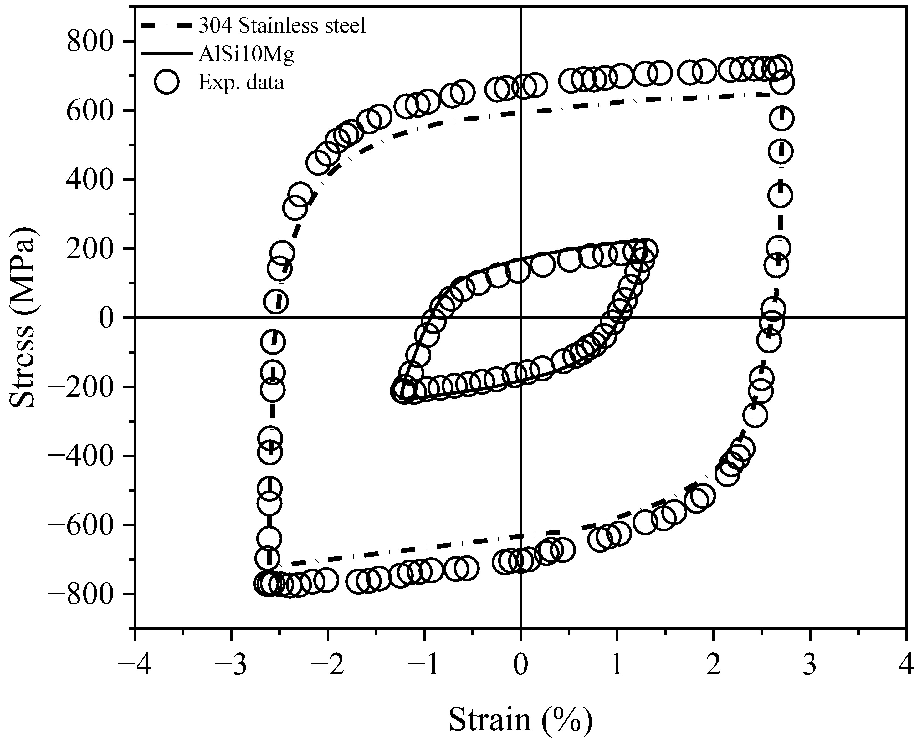
Strain-based cyclic tests for SS304L and AlSi10Mg resulted in the hysteresis loops presented in Figure 3. Figure 3 presents the best-fitted curve of cyclic tests conducted at constant cyclic strain values. For SS304L, cyclic tests were conducted at constant maximum and minimum strains of ±2.5%, while this limit for AlSi10Mg strain-controlled tests was ±1.25%. At constant strains controlled through mounted extensometers, stress values were determined, resulting in strain-based hysteresis loops for these alloys. The constructed loops in Figure 3 have been used to determine Chaboche’s materials model coefficients as input values to simulate the ratcheting response of steel and aluminum samples through finite element analysis. A proper choice of these coefficients results in a stress–strain hysteresis loop to coincide with the loop constructed based on measured data [41,42]. The coefficients of Chaboche’s hardening rule consisting of C 1 3   and   γ 1 3   are listed in Table 1.
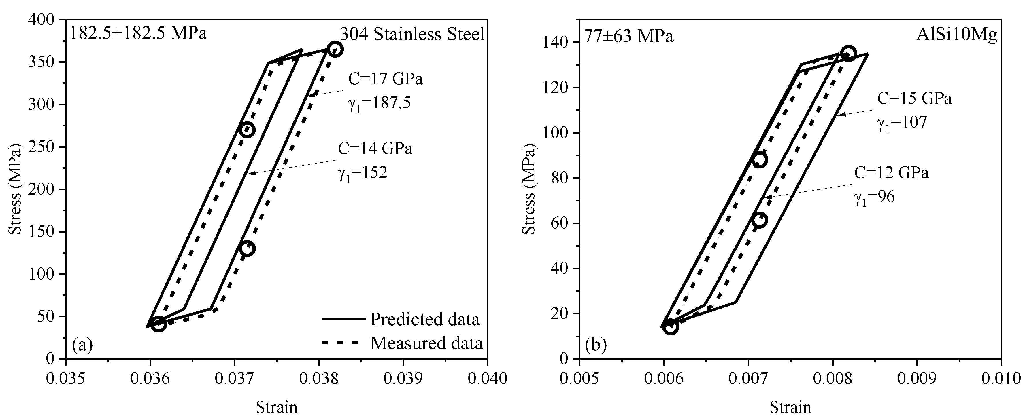
AM samples of SS304L and AlSi10Mg were tested under asymmetric loading cycles under stress-controlled conditions, resulting in a progressive plastic strain accumulation. To predict the ratcheting response of AM samples through the A–V kinematic hardening rule, material-dependent coefficients of C , γ 1 , and γ 2 have to first be determined. The choice of coefficients C and γ 1 results in stress-based loops agreeable with measured loops. Any deviation in these coefficients results from measured values contravening the consistency condition and will result in the overshooting of loops in an irregular manner [24]. Coefficient γ 2 was obtained via uniaxial ratcheting strain plotted versus the number of asymmetric stress cycles. Figure 4 presents stress-controlled loops for SS304L and AlSi10Mg samples at the first stress cycle, satisfying the consistency condition. The predicted and measured hysteresis loops presented in this figure closely agree with a small deviation. The measured loop was constructed through the applied stress-controlled tests for SS304L and AlSi10Mg samples with given stress levels and stress ratios. The average of maximum and minimum strains measured through clip gauges for SS304L and AlSi10Mg were 0.037145 and 0.007135, respectively. The loading paths of this hysteresis loop were determined through the Ramberg–Osgood equation [43]. As the predicted hysteresis loop fell closely to the loop constructed based on the experimental data, the corresponding coefficients of γ 1 and C were determined. Strain-based coefficients of Chaboche’s rule and stress-based coefficients based on the A–V hardening rule for different vertical and horizontal AM samples are tabulated in Table 1. This table also presents fatigue constants for steel and aluminum samples.

3.2. Backstress and Yield Surface Translation

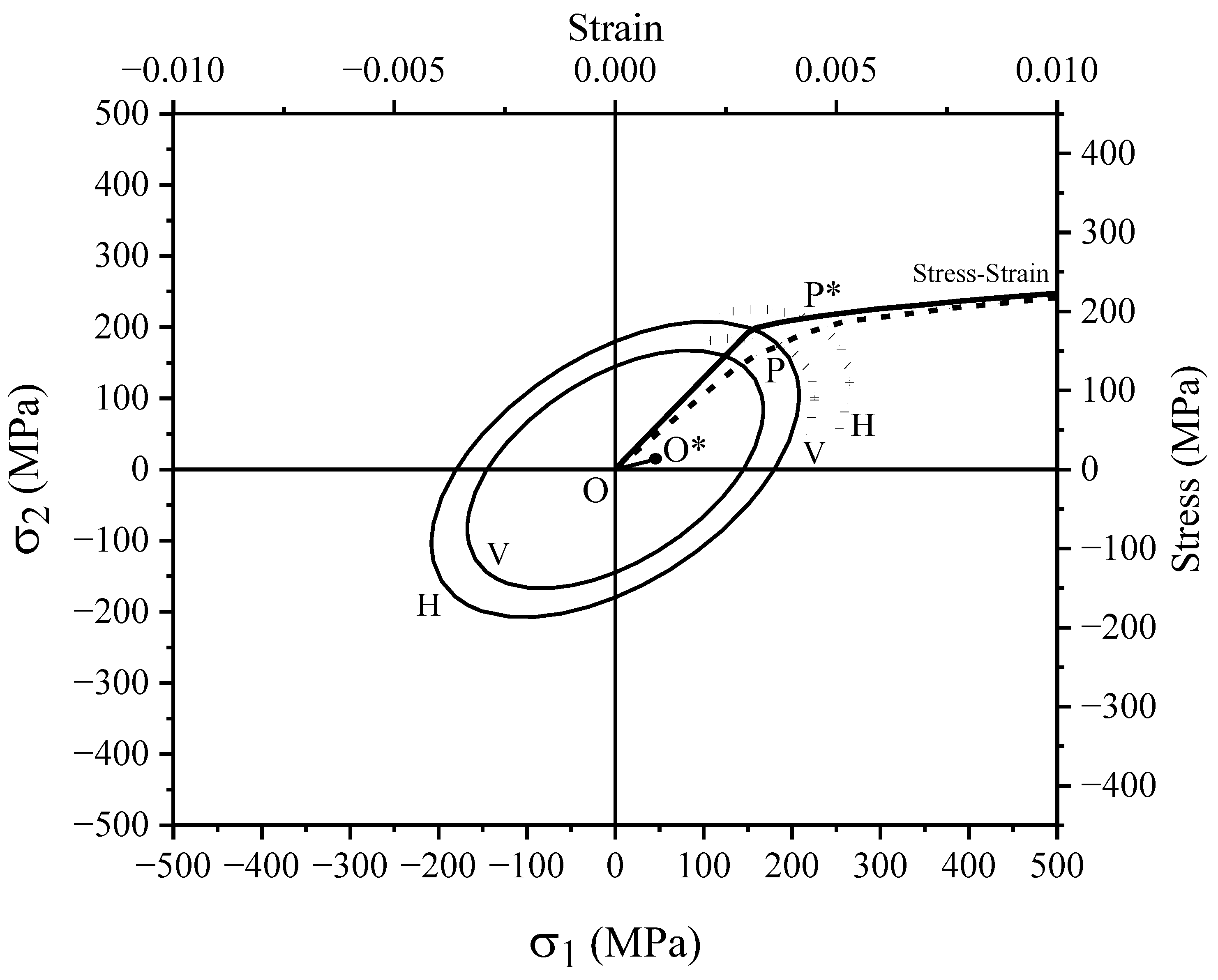
Backstress increments controlled the evolution of yield surfaces for loading beyond the elastic limit. The dynamic recovery term of the A–V model holds terms and coefficients to gradually translate yield surfaces into the deviatoric stress space as backstress increments evolve nonlinearly. The layer-by-layer formation of AM samples resulted in different material characteristics in both sample directions. In AM samples prepared from the horizontal direction, loading orientation coincides with the lay-by-layer building direction of the 3D block. In vertically cut samples, building and loading directions are orthogonal, leading to a noticeable difference in yield surfaces in V and H samples. Figure 5 presents the difference in the yield surface evolution of AlSi10Mg samples taken in the vertical (V) direction and horizontal (H) directions. The initial yield surfaces of the AlSi10Mg alloy samples are plotted with solid lines in this figure. The stress–strain curves of both vertical and horizontal samples were demonstrated through top horizontal and right vertical axes. Beyond the elastic limit, initial yield surfaces are translated, resulting in the movement of center O to center O * . The yield surfaces of vertical and horizontal samples shift over the stress–strain curves, which are shown partially by dot lines and intercept the curves at points P and P * , respectively. The direction of evolution is almost the same for both samples at the same stress level. But the amount of translation for the horizontal sample is larger than for the vertical sample.
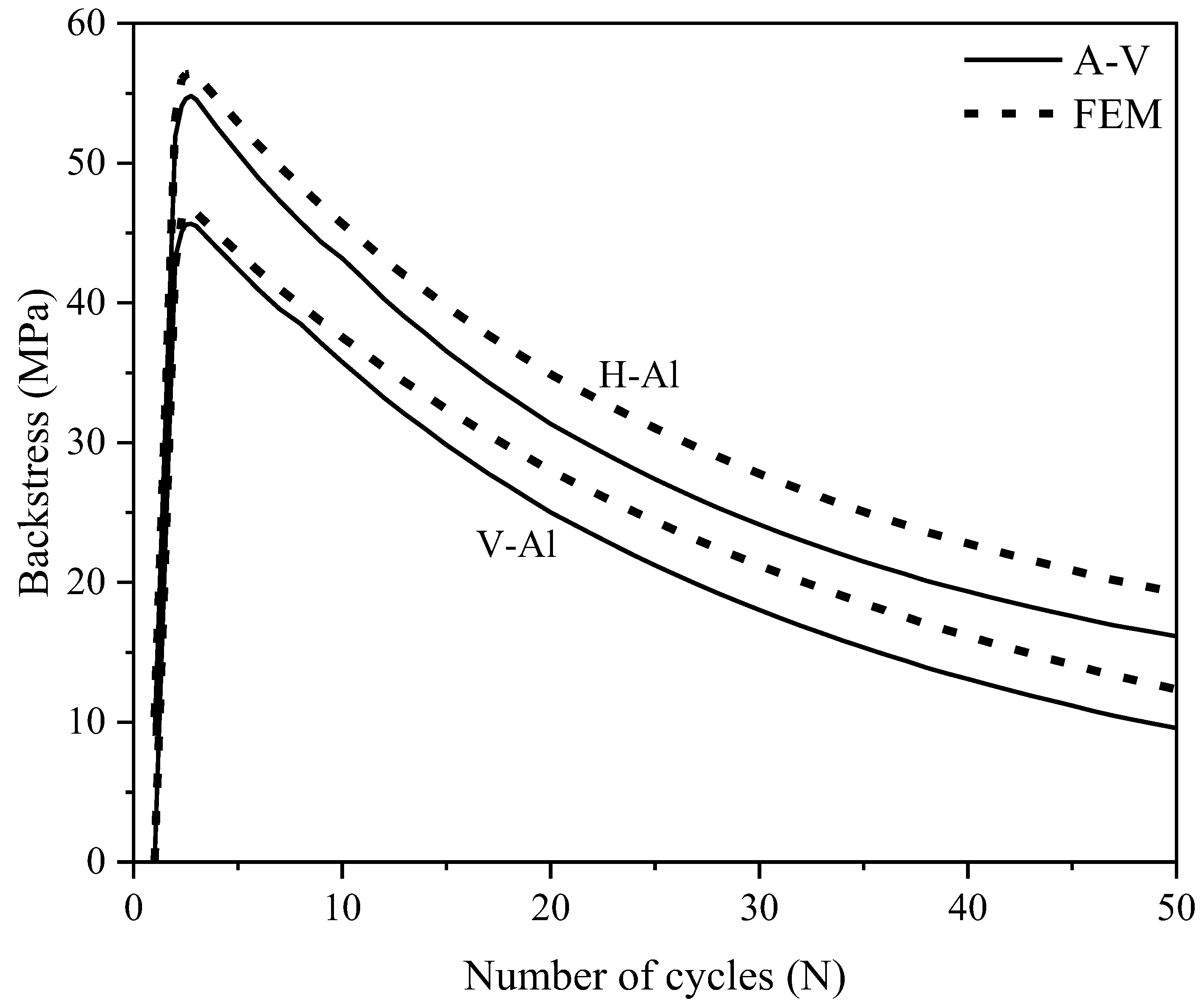
Backstress evolution through the A–V analytical approach and FE numerical approach are presented for AM samples in vertical and horizontal directions. Figure 6 presents the gradual evolution of backstress term ( a ¯ δ b ¯ ) in the dynamic recovery of A–V model and Chaboche’s postulation i = 1 M d α ¯ i . The former controls the trend and magnitude of backstress a ¯ by means of an internal variable b ¯ and the latter integrates backstress increments d α ¯ i through the loading process up a unit to a steady condition. The evolution of backstress in Figure 6 presents similar trends through the A–V and FE models. Horizontally prepared samples show slightly higher values for backstress terms as compared with vertical samples. The predicted backstress through the A–V model collapses below that determined by FE analysis. Larger backstress in horizontal samples is also attributed to the larger translation of initial yield surface of this sample, as depicted in Figure 5.

3.3. Finite Element Analysis

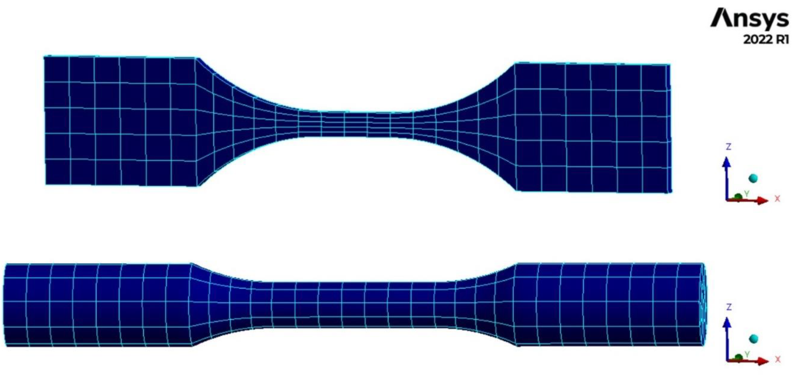
The test samples were studied using the finite element model through the use of Ansys 2022 R1 [44]. SS304L samples with the flat shape geometry had a thickness of 3.81 mm and AlSi10Mg samples with the cylindrical shape were modeled as shown in Figure 7. Volumetric elements were created by the sweeping mesh method through the entire body of samples. With sweep meshing, a body face was meshed and then swept through the body to mesh the volume with solid elements. For flat SS304L samples, quadrilateral elements were used on the exterior face, while for the cylindrical specimen, both triangular and quadrilateral elements were employed. The chosen elements were quadratic in shape and each element consisted of mid-side nodes. The fine elements were adapted to accurately assess maximum and minimum strain values within the gauge length (mid-section area) of samples. Convergence was achieved for SS304L and AlSi10Mg samples, respectively, for 135 and 527 elements. Test samples were fixed at one end by imposing constraints along the x, y, and z directions. Samples were then cycled from the other end along the y-axis of samples. The Chaboche materials model in the finite element software [44] was employed to assess plastic strain accumulation over the asymmetric loading cycles.

3.4. Ratcheting–Fatigue Damage Curves

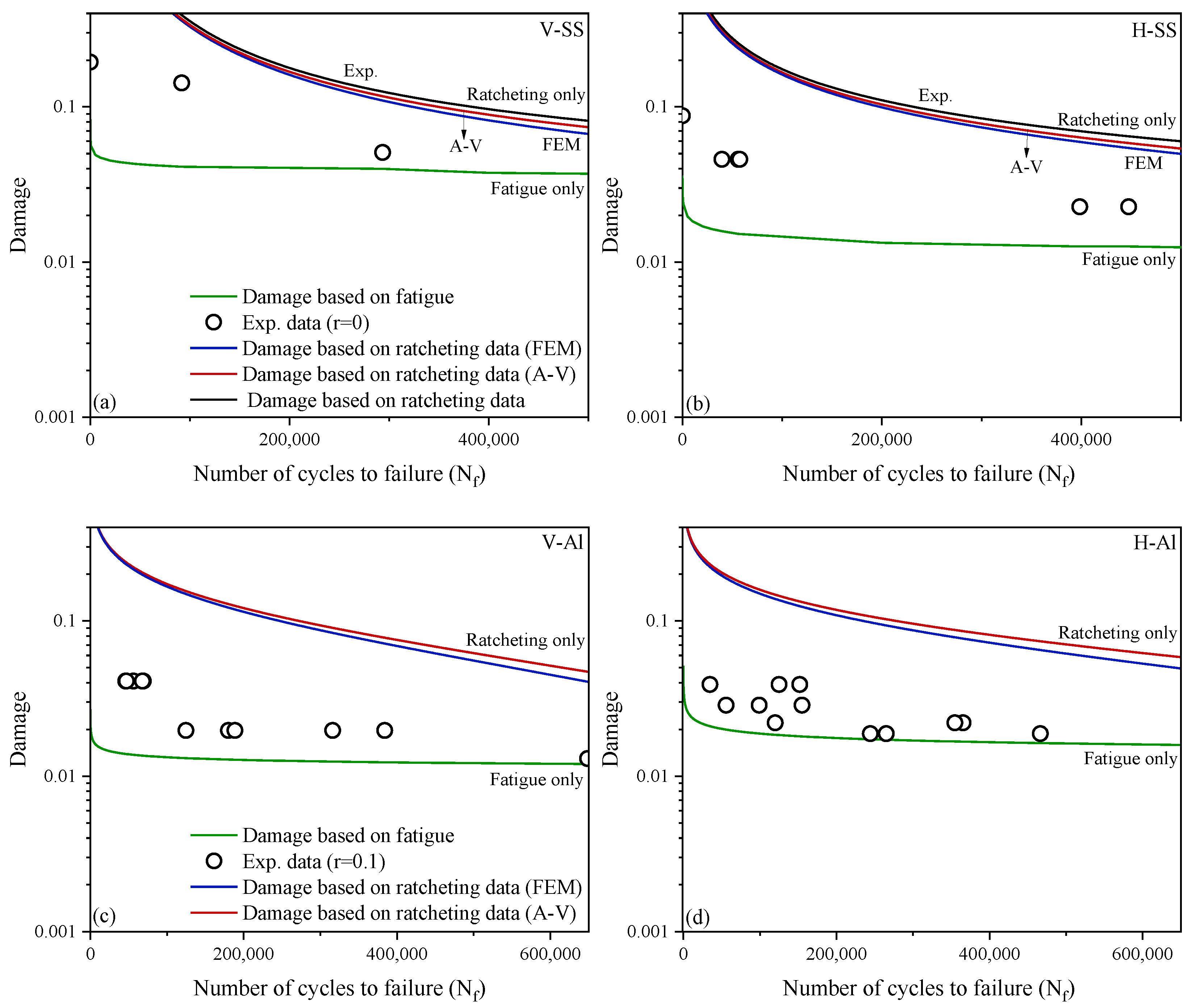
The concurrent fatigue–ratcheting damage of additively manufactured steel and aluminum samples prepared from 3D-printed plates was studied. Asymmetric loading cycles applied on vertical AM samples resulted in noticeably different ratcheting and damage values from those of horizontal samples. Ratcheting strains predicted and simulated, respectively based on hardening framework and FE analysis, were used to construct the upper bound of damage and an energy-based critical plane fatigue damage approach was employed to form the lower bound damage curve. The measured values fell between the upper and lower damage curves and partitioned damage values due to fatigue and ratcheting phenomena at given life cycles. Figure 8 maps fatigue and ratcheting damage curves for SS304L and AlSi10Mg samples versus fatigue lives. The damage curves showed a gradual decay as life cycles increased. The lower damage curve was constructed through the energy-based critical plane fatigue damage approach through Equation (1) for fully reversed loading conditions (r = −1) in the absence of ratcheting. The upper damage curve quantifies damage due to asymmetric loading cycles, leading to ratcheting through Equation (2). The lower and upper damage curves, respectively expressed by Equations (1) and (2), operate as a function of fatigue life N.
Ratcheting damage values predicted through the A–V model and simulated through the FE analysis closely agreed with one another and formed the upper damage curves with a small deviation as low as 10%. Cyclic test data positioned between the upper and lower damage curves consisted of partitions of damage induced from ratcheting and fatigue phenomena. Figure 8a,b present damage curves for vertical and horizontal samples made of SS304L alloy. The stress ratio in these figures is zero (r = 0) where stress cycles fluctuate between zero and maximum applied stress. AM samples of AlSi10Mg similarly held upper and lower damage bounds in Figure 8c,d. To determine overall damage data falling between these bounds, Varvani’s fatigue damage model (Equation (1)) was employed, wherein the mean stress effect was taken into account through σ n m . Experimental data presented in Figure 8 show a closer distance to the lower bound damage, wherein the damage curve solely implies fatigue phenomenon at r = −1, in the absence of ratcheting. The closer data point to lower curve verifies the fact that severe damage in the tested samples is dominantly due to fatigue and ratcheting, resulting in a smaller weight of damage. The weighting factor ξ for such data possesses larger value for fatigue damage and smaller values of ( 1 ξ ) as a contribution of ratcheting damage.

Contribution of Fatigue and Ratcheting Damage

The contribution of fatigue and ratcheting in the overall damage of material was found to differ in various stress levels. Experimental data positioning closer to the bottom curve in Figure 8 imply the larger contribution of fatigue damage and smaller damage weight due to ratcheting in the failure of AM samples. The damage weights of fatigue and ratcheting are presented in Figure 9 in the form of bar charts. This figure exhibits the weight of fatigue and ratcheting phenomena in the overall damage of AM samples for vertical and horizontal directions. Aluminum samples were tested with a larger stress ratio of 0.1 as compared with those steel samples tested with a ratio of zero. As the stress ratio increased in magnitude, the ratcheting damage in AM samples was further promoted. The contribution of fatigue damage for the cyclically tested samples of SS304L and AlSi10Mg stayed higher than the weight of ratcheting damage. Through interpolation and partitioning the weight of damage due to both phenomena, the failed samples underwent over 70% fatigue damage and the remaining 20–30% damage resulted from ratcheting. The bar charts presented in Figure 9 clearly partition damage weights for several vertical and horizontal samples tested at various stress levels.
The interaction of fatigue and ratcheting in additively manufactured steel and aluminum samples undergoing uniaxial loading cycles necessitated the use of a hardening framework along with a fatigue damage model. The former enabled ratcheting assessment and the latter evaluated cycle-by-cycle damage accumulated in the materials plane during loading cycles. The coupled fatigue and ratcheting severely promoted damage over loading cycles and resulted in accelerated failure in AM samples. To better quantify overall damage, both phenomena were formulated in an analogous format and damage values were integrated. A weighting factor was employed to partition damage quantities through the interpolation of measured values based on upper and lower damage curves. Several variables and parameters influenced overall damage as the fatigue and ratcheting of SS304L and AlSi10Mg were investigated. The orientation of the AM sample prepared from the 3D-printed sample influenced the ratcheting and fatigue data. Samples with the horizontal direction experienced loading cycles along the layer-by-layer fabrication direction, resulting in better material characteristics in the H-samples. The horizontal samples improved the initial yield surface and corresponded to a larger yield surface translation as loading progressed beyond the elastic limit. A higher level of backstress in this direction improved its resistance against fatigue and ratcheting as compared with those AM samples prepared along the vertical direction. While the present study involved several hardening and fatigue parameters and variables to assess the overall damage, the concurrent ratcheting–fatigue phenomenon is yet a challenging research subject, particularly in additively manufactured components. Besides influential theoretical parameters in cyclic plasticity, the ratcheting and fatigue of load-bearing AM parts, some major technical issues including AM sample orientation, post-processing, layer-by-layer fabrication speed, interval time and temperature between subsequent layers, as well as surface roughness and porosity between deposited layers require an intensive research investigation. As the next research step, the authors believe that more research should be conducted to develop theories and run experiments on AM samples to achieve more reliable solutions for complex geometries and fatigue–ratcheting interactions.

4. Conclusions

The ratcheting–fatigue interaction of SS304L and AlSi10Mg samples was studied through analytical and numerical approaches. Under uniaxial loading cycles, upper and lower damage bounds were developed through a hardening framework and a fatigue damage approach, respectively. The upper curve (ratcheting damage curve) was formulated through the product of the applied stress range and ratcheting strain just before failure. Ratcheting strain was predicted through a combined isotropic–kinematic hardening framework. The lower curve (fatigue damage curve) was mapped through the use of an energy-based critical plane damage approach involving the product of stress and strain ranges acting on the most damaging plane in materials. The simulated ratcheting damage curve was structured based on Chaboche’s materials model in finite element Ansys software. Overall damage was partitioned through an interpolation from the upper and lower damage curves for experimental data falling between the curves. A weighting factor was adapted to evaluate damage weights due to ratcheting and fatigue phenomena. The choice of partitioning overall damage into fatigue damage and ratcheting damage enables a reliable design of additively manufactured samples through proper applied stress levels, mean stress, operating temperature, post-processing techniques, and technical control process to minimize the risk of severe damage in load-bearing AM components.

Author Contributions

Conceptualization, M.S. and A.V.-F.; methodology, M.S. and A.V.-F.; software, M.S. and A.V.-F.; validation, M.S., A.V.-F. and S.M.H.; formal analysis, M.S.; investigation, M.S. and A.V.-F.; data curation, M.S. and A.V.-F.; writing—original draft preparation, M.S. and A.V.-F.; writing—review and editing, M.S. and A.V.-F.; visualization, M.S. and A.V.-F.; supervision, A.V.-F. and S.M.H.; project administration, A.V.-F.; funding acquisition, A.V.-F. and S.M.H. All authors have read and agreed to the published version of the manuscript.

Funding

This research was funded by Natural Sciences and Engineering Research Council of Canada (NSERC), through A.V.-F. (RGPIN-2021-03047) and S.M.H. (RGPIN-2017-06868).

Data Availability Statement

Data will be made available upon request.

Acknowledgments

The authors wish to acknowledge the financial support through the Natural Sciences and Engineering Research Council of Canada (NSERC) through Varvani (RGPIN-2021-03047) and Hashemi (RGPIN-2017-06868).

Conflicts of Interest

The authors declare that they have no known competing financial interest or personal relationships that could have appeared to influence the work reported in this paper.

References

  1. Blakey-Milner, B.; Gradl, P.; Snedden, G.; Brooks, M.; Pitot, J.; Lopez, E.; Leary, M.; Berto, F.; Du Plessis, A. Metal additive manufacturing in aerospace: A review. Mater. Des. 2021, 209, 110008. [Google Scholar] [CrossRef]
  2. Montanari, R.; Palombi, A.; Richetta, M.; Varone, A. Additive Manufacturing of Aluminum Alloys for Aeronautic Applications: Advantages and Problems. Metals 2023, 13, 716. [Google Scholar] [CrossRef]
  3. Gu, D.; Shi, X.; Poprawe, R.; Bourell, D.L.; Setchi, R.; Zhu, J. Material-structure-performance integrated laser-metal additive manufacturing. Science 2021, 372, eabg1487. [Google Scholar] [CrossRef] [PubMed]
  4. Molaei, R.; Fatemi, A.; Sanaei, N.; Pegues, J.; Shamsaei, N.; Shao, S.; Li, P.; Warner, D.H.; Phan, N. Fatigue of additive manufactured Ti-6Al-4V, Part II: The relationship between microstructure, material cyclic properties, and component performance. Int. J. Fatigue 2020, 132, 105363. [Google Scholar] [CrossRef]
  5. Mostafaei, A.; Zhao, C.; He, Y.; Ghiaasiaan, S.R.; Shi, B.; Shao, S.; Shamsaei, N.; Wu, Z.; Kouraytem, N.; Sun, T.; et al. Defects and anomalies in powder bed fusion metal additive manufacturing. Curr. Opin. Solid State Mater. Sci. 2022, 26, 100974. [Google Scholar]
  6. Sanaei, N.; Fatemi, A. Defects in additive manufactured metals and their effect on fatigue performance: A state-of-the-art review. Prog. Mater. Sci. 2021, 117, 100724. [Google Scholar] [CrossRef]
  7. Mower, T.M.; Long, M.J. Mechanical behavior of additive manufactured, powder-bed laser-fused materials. Mater. Sci. Eng. 2016, 651, 198–213. [Google Scholar] [CrossRef]
  8. Siddique, S.; Imran, M.; Rauer, M.; Kaloudis, M.; Wycisk, E.; Emmelmann, C.; Walther, F. Computed tomography for characterization of fatigue performance of selective laser melted parts. Mater. Des. 2015, 83, 661–669. [Google Scholar] [CrossRef]
  9. Avanzini, A.; Battini, D.; Gelfi, M.; Girelli, L.; Petrogalli, C.; Pola, A.; Tocci, M. Investigation on fatigue strength of sand-blasted DMLS-AlSi10Mg alloy. Procedia Struct. Integrity 2019, 18, 119–128. [Google Scholar] [CrossRef]
  10. Aboulkhair, N.T.; Everitt, N.M.; Ashcroft, I.; Tuck, C. Reducing porosity in AlSi10Mg parts processed by selective laser melting. Addit. Manuf. 2014, 1, 77–86. [Google Scholar] [CrossRef]
  11. Li, P.; Warner, D.H.; Fatemi, A.; Phan, N. Critical assessment of the fatigue performance of additively manufactured Ti–6Al–4V and perspective for future research. Int. J. Fatigue 2016, 85, 130–143. [Google Scholar] [CrossRef]
  12. Masuo, H.; Tanaka, Y.; Morokoshi, S.; Yagura, H.; Uchida, T.; Yamamoto, Y.; Murakami, Y. Effects of defects, surface roughness and HIP on fatigue strength of Ti-6Al-4V manufactured by additive manufacturing. Procedia Struct. 2017, 7, 19–26. [Google Scholar] [CrossRef]
  13. Jeyaprakash, N.; Yang, C.H.; Ramkumar, K.R. Correlation of microstructural evolution with mechanical and tribological behaviour of SS 304 specimens developed through SLM technique. Met. Mater. Int. 2021, 27, 5179–5190. [Google Scholar] [CrossRef]
  14. Shrestha, R.; Simsiriwong, J.; Shamsaei, N. Fatigue behavior of additive manufactured 316L stainless steel parts: Effects of layer orientation and surface roughness. Addit. Manuf. 2019, 28, 23–38. [Google Scholar] [CrossRef]
  15. Zhang, M.; Sun, C.N.; Zhang, X.; Goh, P.C.; Wei, J.; Hardacre, D.; Li, H. Fatigue and fracture behaviour of laser powder bed fusion stainless steel 316L: Influence of processing parameters. Mater. Sci. Eng. 2017, 703, 251–261. [Google Scholar] [CrossRef]
  16. Fatemi, A.; Molaei, R.; Simsiriwong, J.; Sanaei, N.; Pegues, J.; Torries, B.; Shamsaei, N. Fatigue behaviour of additive manufactured materials: An overview of some recent experimental studies on Ti-6Al-4V considering various processing and loading direction effects. Fatigue Fract. Eng. Mater. Struct. 2019, 42, 991–1009. [Google Scholar] [CrossRef]
  17. Leuders, S.; Thöne, M.; Riemer, A.; Niendorf, T.; Tröster, T.; Richard, H.A.; Maier, H.J. On the mechanical behaviour of titanium alloy TiAl6V4 manufactured by selective laser melting: Fatigue resistance and crack growth performance. Int. J. Fatigue 2013, 48, 300–307. [Google Scholar] [CrossRef]
  18. Molaei, R.; Fatemi, A.; Phan, N. Significance of hot isostatic pressing (HIP) on multiaxial deformation and fatigue behaviors of additive manufactured Ti-6Al-4V including build orientation and surface roughness effects. Int. J. Fatigue 2018, 117, 352–370. [Google Scholar] [CrossRef]
  19. Wang, Y.; Yang, S.L.; Gu, J.X.; Duan, C.F.; Xiong, Q. Effect of ratcheting strain on mechanical properties of additive manufactured 4043 aluminum alloy. Key Eng. Mater. 2019, 795, 43–48. [Google Scholar]
  20. Dong, B.; Cai, X.; Lin, S.; Li, X.; Fan, C.; Yang, C.; Sun, H. Wire arc additive manufacturing of Al-Zn-Mg-Cu alloy: Microstructures and mechanical properties. Addit. Manuf. 2020, 36, 101447. [Google Scholar] [CrossRef]
  21. Ghosh, A.; Sahu, V.K.; Gurao, N.P. Effect of heat treatment on the ratcheting behaviour of additively manufactured and thermo-mechanically treated Ti–6Al–4V alloy. Mater. Sci. Eng. 2022, 833, 142345. [Google Scholar] [CrossRef]
  22. Servatan, M.; Hashemi, S.M.; Varvani-Farahani, A. Ratcheting assessment of additively manufactured alloys through the hardening framework: Analysis and simulation. Mater. Today Commun. 2023, 35, 105916. [Google Scholar] [CrossRef]
  23. Zhang, M.; Sun, C.N.; Zhang, X.; Wei, J.; Hardacre, D.; Li, H. High cycle fatigue and ratcheting interaction of laser powder bed fusion stainless steel 316L: Fracture behaviour and stress-based modelling. Int. J. Fatigue 2019, 121, 252–264. [Google Scholar] [CrossRef]
  24. Servatan, M.; Hashemi, S.M.; Varvani-Farahani, A. Ratcheting evaluation of additively manufactured 4043 aluminum samples through a combined isotropic–kinematic hardening framework. Prog. Addit. Manuf. 2023, 8, 667–678. [Google Scholar] [CrossRef]
  25. Xia, Z.; Kujawski, D.; Ellyin, F. Effect of mean stress and ratcheting strain on fatigue life of steel. Int. J. Fatigue 1996, 18, 335–341. [Google Scholar] [CrossRef]
  26. Liu, Y.; Kang, G.; Gao, Q. Stress-based fatigue failure models for uniaxial ratchetting–fatigue interaction. Int. J. Fatigue 2008, 30, 1065–1073. [Google Scholar] [CrossRef]
  27. Kang, G.; Liu, Y.; Li, Z. Experimental study on ratchetting-fatigue interaction of SS304 stainless steel in uniaxial cyclic stressing. Mater. Sci. Eng. 2006, 435, 396–404. [Google Scholar] [CrossRef]
  28. Ahmadzadeh, G.R.; Varvani-Farahani, A. Concurrent ratcheting–fatigue damage analysis of uniaxially loaded A-516 Gr. 70 and 42CrMo Steels. Fatigue Fract. Eng. Mater. Struct. 2012, 35, 962–970. [Google Scholar] [CrossRef]
  29. Zhan, Z.; Li, H. A novel approach based on the elastoplastic fatigue damage and machine learning models for life prediction of aerospace alloy parts fabricated by additive manufacturing. Int. J. Fatigue 2021, 145, 106089. [Google Scholar] [CrossRef]
  30. Varvani-Farahani, A. A new energy-critical plane parameter for fatigue life assessment of various metallic materials subjected to in-phase and out-of-phase multiaxial fatigue loading conditions. Int. J. Fatigue 2000, 22, 295–305. [Google Scholar] [CrossRef]
  31. Karvan, P.; Varvani-Farahani, A. Isotropic-kinematic hardening framework to assess ratcheting response of steel samples undergoing asymmetric loading cycles. Fatigue Fract. Eng. Mater. Struct. 2019, 42, 295–306. [Google Scholar] [CrossRef]
  32. Lee, D.; Zaverl, F., Jr. A generalized strain rate dependent constitutive equation for anisotropic metals. Acta Metall. 1978, 26, 1771–1780. [Google Scholar] [CrossRef]
  33. Ahmadzadeh, G.R.; Varvani-Farahani, A. Ratcheting assessment of materials based on the modified Armstrong–Frederick hardening rule at various uniaxial stress levels. Fatigue Fract. Eng. Mater. Struct. 2013, 36, 1232–1245. [Google Scholar] [CrossRef]
  34. Varvani-Farahani, A. Nonlinear kinematic hardening cyclic plasticity. In Cyclic Plasticity of Metals; Elsevier: Amsterdam, The Netherlands, 2022; pp. 139–174. [Google Scholar]
  35. Chaboche, J.L. On some modifications of kinematic hardening to improve the description of ratchetting effects. Int. J. Plast. 1991, 7, 661–678. [Google Scholar] [CrossRef]
  36. Gordon, J.; Hochhalter, J.; Haden, C.; Harlow, D.G. Enhancement in fatigue performance of metastable austenitic stainless steel through directed energy deposition additive manufacturing. Mater. Des. 2019, 168, 107630. [Google Scholar] [CrossRef]
  37. Gordon, J.V.A. Fatigue Crack Growth Analysis of 3D Printed Type 304 Stainless Steel. Ph.D. Thesis, Lehigh University, Bethlehem, PA, USA, 2018. [Google Scholar]
  38. Wu, Z.; Wu, S.; Bao, J.; Qian, W.; Karabal, S.; Sun, W.; Withers, P.J. The effect of defect population on the anisotropic fatigue resistance of AlSi10Mg alloy fabricated by laser powder bed fusion. Int. J. Fatigue 2021, 151, 106317. [Google Scholar] [CrossRef]
  39. Yu, T.; Hyer, H.; Sohn, Y.; Bai, Y.; Wu, D. Structure-property relationship in high strength and lightweight AlSi10Mg microlattices fabricated by selective laser melting. Mater. Des. 2019, 182, 108062. [Google Scholar] [CrossRef]
  40. Vivekananthan, M.; Saravanakumar, M.; Ross, K.N.S.; Kumar, K.S.S.; Raj, F.S. Experimental investigation of Mechanical properties in friction welding parameters for dis-similar metals (SS-304 & SS-410). Manuf. Eng. 2020, 2214, 7853. [Google Scholar]
  41. Halama, R.; Fumfera, J.; Gál, P.; Kumar, T.; Markopoulos, A. Modeling the strain-range dependent cyclic hardening of SS304 and 08Ch18N10T stainless steel with a memory surface. Metals 2019, 9, 832. [Google Scholar] [CrossRef]
  42. Fernandes, R.; de Jesus, J.; Branco, R.; Borrego, L.P.; Ferreira, J.M. Cyclic deformation behaviour of AlSi10Mg aluminium alloy manufactured by laser-beam powder bed fusion. Procedia Struct. Integr. 2022, 37, 462–468. [Google Scholar] [CrossRef]
  43. Skelton, R.P.; Maier, H.J.; Christ, H.J. The Bauschinger effect, Masing model and the Ramberg–Osgood relation for cyclic deformation in metals. Mater. Sci. Eng. 1997, 238, 377–390. [Google Scholar] [CrossRef]
  44. Ansys® Workbench, Release 22.1. Help System, Static Structural Analysis Guide; ANSYS, Inc.: Canonsburg, PA, USA, 2022. [Google Scholar]
Figure 1. Stress–strain curves for additively manufactured (a) SS304L and (b) AlSi10Mg alloys.
Metals 13 01534 g001
Figure 2. Stress range versus number of cycles to failure for horizontal (H) and vertical (V) AM samples of (a) SS304L and (b) AlSi10Mg.
Metals 13 01534 g002
Figure 3. Predicted strain-based hysteresis loops through the Chaboche model closely agreed with those measured values reported in references [41,42] for SS304L and AlSi10Mg alloys.
Metals 13 01534 g003
Figure 4. Measured and predicted stress-controlled stress–strain hysteresis loops for (a) SS304L and (b) AlSi10Mg alloys.
Metals 13 01534 g004
Figure 5. Yield surface evolution of vertical (V) and horizontal (H) samples made of AlSi10Mg alloy.
Metals 13 01534 g005
Figure 6. Backstress evolution through the A–V and Chaboche hardening rules for vertical (V) and horizontal (H) AM samples made of AlSi10Mg.
Metals 13 01534 g006
Figure 7. Meshed samples of SS304L and AlSi10Mg through Ansys software.
Metals 13 01534 g007
Figure 8. Predicted and simulated damage upper curves and predicted fatigue damage lower curve for vertical and horizontal samples of (a,b) SS304L and (c,d) AlSi10Mg.
Metals 13 01534 g008
Figure 9. Bar charts to partition fatigue and ratcheting damage values at different stress levels and AM specimen directions for (a,b) SS304L and (c,d) AlSi10Mg.
Metals 13 01534 g009
Table 1. Hardening rule and fatigue coefficients for SS304L and AlSi10Mg alloys.
MaterialFatigue CoefficientsModelsParameters and Coefficients
σ f , = 4000 Isotropic Q   ( MPa ) = 90 , b = 13.5
304L Stainless Steel (Horizontal samples) ε f , = 0.016A–V C   ( GPa ) = 16 , γ 1 = 195 , γ 2 = 20
b = −0.06
c = −0.3
Chaboche C 1 3   ( GPa ) = 44 ,   37 ,   25 , γ 1 3 = 110 ,   115 ,   0
σ f , = 4200Isotropic Q   ( MPa ) = 79 , b = 12.5
304L Stainless Steel (Vertical samples) ε f , = 0.026A–V C   ( GPa ) = 17 , γ 1 = 187.5 , γ 2 = 10
b = −0.184
c = −0.2
Chaboche C 1 3   ( GPa ) = 50 ,   35 ,   25 , γ 1 3 = 100 ,   120 ,   0
σ f , = 330Isotropic Q   ( MPa ) = 260 , b = 3.5
AlSi10Mg (Horizontal samples) ε f , = 0.024A–V C   ( GPa ) = 15 , γ 1 = 90 , γ 2 = 40
b = −0.005
−0.2
Chaboche C 1 3   ( GPa ) = 180 ,   120 ,   33 , γ 1 3 = 1200 ,   600 ,   0
σ f , = 320Isotropic Q   ( GPa ) = 250 , b = 2.5
AlSi10Mg (Vertical samples) ε f , = 0.01A–V C   ( GPa ) = 12 , γ 1 = 96 , γ 2 = 30
b = −0.005
c = −0.2
Chaboche C 1 3   ( GPa ) = 140 ,   100 ,   28 , γ 1 3 = 1500 ,   800 ,   0
Disclaimer/Publisher’s Note: The statements, opinions and data contained in all publications are solely those of the individual author(s) and contributor(s) and not of MDPI and/or the editor(s). MDPI and/or the editor(s) disclaim responsibility for any injury to people or property resulting from any ideas, methods, instructions or products referred to in the content.