Article

The Stray Grains from Fragments in the Rejoined Platforms of Ni-Based Single-Crystal Superalloy

1
School of Materials Science and Engineering, Xi’an Shiyou University, Xi’an 710065, China
2
State Key Laboratory of Solidification Processing, Northwestern Polytechnical University, Xi’an 710072, China
*
Author to whom correspondence should be addressed.
Metals 2023, 13(8), 1470; https://doi.org/10.3390/met13081470
Submission received: 10 June 2023 / Revised: 23 July 2023 / Accepted: 10 August 2023 / Published: 15 August 2023
(This article belongs to the Special Issue Solidification and Casting of Metals and Alloys)

Abstract

:
Nickel-based single crystal superalloy is the most important material for blade preparation. However, some solidification defects inevitably occur during the process of preparing single-crystal blades through directional solidification. In this study, in order to study the origin of misorientation defects during solidification, a model with rejoined platforms was designed according to the geometry of single-crystal guide vanes. Electron Back-Scattering Diffraction (EBSD) was used to quantify the orientation deviation of the dendrites and identify the solidification defects in the rejoined platforms. The results showed that stray grain defects appeared in the platforms and their misorientation changed gradually, not abruptly. Combined with the simulation results, it was proposed that the stray grains formed as the result of the dendrites fragment, which was induced by solute enrichment in the mushy zone during solidification. Meanwhile, it was accompanied by a obvious dendritic deformation, which was caused by solidification shrinkage stress. This suggested that the fragmentation was induced by multiple factors, among which, the concave interface shape provided favorable conditions for solute enrichment, and the dynamic variability in the local thermal gradient and fluctuations of the solidification rate might play catalytic roles.

1. Introduction

Due to the complex shapes of the turbine blades and guide vanes in advanced gas turbine systems, investment single-crystal (SX) casting is the preferred manufacturing route [1]. There are two prevalent techniques for fabricating SX blades: the grain selection technique and the seeding method. However, no matter which method is adopted, misorientation defects [2,3,4] are almost inevitable. Stray grain (SG) defects are common, particularly around the platforms and shroud regions [5,6,7,8,9] of the turbine blade, and can lead to component invalidation.
Therefore, some studies about the formation of stray grains in single-crystal superalloy have been carried out. In 1996, Meyer et al. [8] first depicted that SGs nucleated in a thermally undercooled zone caused by a macroscopically curved liquidus isotherm in the platform ends. In 1997, Bussac et al. [10] made a mathematical deduction and derived a criterion to predict SG formation at abrupt cross-sections, which was based on several assumptions rather than an actual casting process. Later, a lot of efforts were paid to investigating the influencing factors of SG formation: withdrawal rates and isothermal inclination angles [7], the undercoolabilities of superalloys [11], alloy composition [12], platform dimension [13], and grain orientation [14]. However, all these studies were based on the presumable fact that SGs are caused by heterogeneous nucleation. In fact, some SGs in platforms originate from dendrite deformation or dendrite fragmentation. In 2011, Zhou et al. [15] proposed that the occurrence of SGs at diverging boundaries was not caused by nucleation, but by the bending or detachment of side arms. In fact, as early as 1996, Meyer et al. [8] found a fine dentritic structure in the corners of a shroud, but they did not provide an explanation for this phenomenon. In 2009, Ma et al. [16] also found a similar dendritic structure of fine equiaxed grains in the overhanging parts of the shrouds with no heat conductor. They called them interdendritic micro equiaxed grains. Because the dendrite trunks were still “single crystal”, they held a view that these grains could only damage the local monocrystality. Finally, they analyzed the formation mechanism of this defect and concluded that the dendrite roots in the undercooled melt were weak and could partially remelt during the subsequent coarsening process caused by the recalescence upon the sudden release of latent heat. Furthermore, Hao et al. [17] found a large number of misoriented grains between the primarily solidified dendrite stems in the specially shaped shroud during the directional solidification process. They attributed this phenomenon to the process of recalescence, which was caused by the accumulation of the solidification of latent heat. Wang et al. [18] also observed fine equiaxed grains in the interdendritic regions at the lowest shroud of single-crystal blades. They analyzed two formation mechanisms for this solidification defect. The first mechanism they analyzed was consistent with the viewpoint of Ma et al. [16]. They inferred that the undercooling of the melt provided a possibility for these grains, and positive segregation elements accumulating easily during transverse growth could have further refined the roots of the dendrite arms, some of which were remelted as a result of the sudden release of the latent heat of the recoalescence. The second formation mechanism they proposed was that the fine equiaxed grains appeared to be a fragmentation of the secondary dendrite arms caused by the contraction stress in the mushy zone during solidification. After that, Sun et al. [19] also discovered severe equiaxed grain defects in the platforms of a simplified turbine blade when studying dendrite deformation in Ni-based superalloys. However, they did not provide any explanation, possibly because there were too many factors affecting this type of defect. In summary, in Ni-based single-crystal superalloys, the formation of such defects might be related to latent heat, melt undercooling, or stress, but no consensus has been reached. In other alloy systems, in situ observation technology has been used to investigate the dendrite growth during the solidification process. The experimental results of a Sn-Bi alloy [20] and Al-20 wt.% Cu [21] revealed that the fragments could also be the source of an SG defect. The fragments were always accompanied by instability and solute segregation during the solidification process. It can be seen that such defects are common, but their formation mechanism is still unclear; thus, it is necessary to conduct further investigations.
At the present stage, it is quite difficult to conduct a real-time observation of the solidification process, dendrite growth, and dendrite fragment of superalloys, because of their high melting point. Therefore, very little is known about the factors that promote the SG defect from fragments during directional solidification. Therefore, the present study was carried out to explore the origin of these fragments through an experimental investigation and finite element simulation using ProCAST.

2. Experimental and Simulation Methods

2.1. Experiment Methods

A model consisting of 3 rejoined platforms (from bottom to top, labelled 1, 2, and 3, respectively) and transverse cylindrical bars with the same diameter (ϕ8 mm) and an equal length (52 mm) (Figure 1a) was used to fabricate single-crystal castings. The single-crystal castings were prepared using a modified Bridgman directional casting furnace. The furnace mainly consisted of a vacuum induction melting unit, a graphite heater unit, and a cooling zone (Figure 1b). During the process of directional solidification, the furnace chamber was evacuated and the ceramic mold was preheated. Molten DD6 (composition in Table 1) was poured into the mold and maintained for 10–20 min. Finally, the ceramic mold was withdrawn from the furnace at a controlled withdrawal rate of 150 μm/s.
After the casting process, the remnant mold was removed with sandpaper and the casting was cleared. Then, the platforms were sectioned from the sample longitudinally and transversely and prepared for a metallographic analysis. In order to reveal the microstructure, well-polished specimens were etched with a solution of HNO3, HF, and C3H8O3 (volume ratio 1:2:4). The microstructure was observed using optical microscopy (OM; Leica DM-4000 M, Leica, Berlin, Germany).
An Electron Back-Scattering Diffraction (EBSD) measurement was employed to determine the crystallographic orientations of the dendrites. The platform samples were mechanically polished to remove stress and obtain a flat surface. The EBSD measurements were performed in ZEISS SUPRA 55 SEM (Carl Zeiss, Inc., Oberkochen, Germany) equipped with an HKL system and Channel 5 analysis software (Oxford instruments, Oxford, UK). During the EBSD scanning process, a step size of 40 μm was used for the EBSD mapping. All-Euler maps and pole figures of the EBSD results were obtained using the Channel 5 analysis software.

2.2. Simulation Methods

The castings were simulated using a finite element analysis with ProCAST in order to exhibit the thermal profile that evolved during the directional solidification process. The solidus and liquidus temperatures of the alloy were determined to be 1342 and 1399 °C, respectively, using a differential scanning calorimetry (DSC) analysis. The simulation was initiated before the withdrawal; the melt and chill-plate temperatures were set to 1550 and 400 °C, respectively. In order to make the simulation results as accurate as possible, the meshing size was set to 1 mm. The boundary conditions, initial conditions, and interfacial heat transfer coefficients were listed in reference [22].
Such simulations are relatively routine. The salient points of the calculations are highlighted below:
(1)
The simulation models of the castings were constructed according to the actual dimensions. The thickness of the ceramic shell was assigned to be 7 mm from the actual measurement.
(2)
The heat transfer was assumed to be heat conduction and radiation, and heat convection was ignored. The coefficients of the thermal emissivity and thermal conductivity were gained from reference [23,24,25,26] or from the experiments. The thermophysical parameters were calculated using the commercial software JMatPro (Trade Mark of Sente Software Ltd. Surrey Technology Center, Surrey GU2 7YG, UK). The thermal results were validated through a thermocouple instrumented experiment.

3. Results

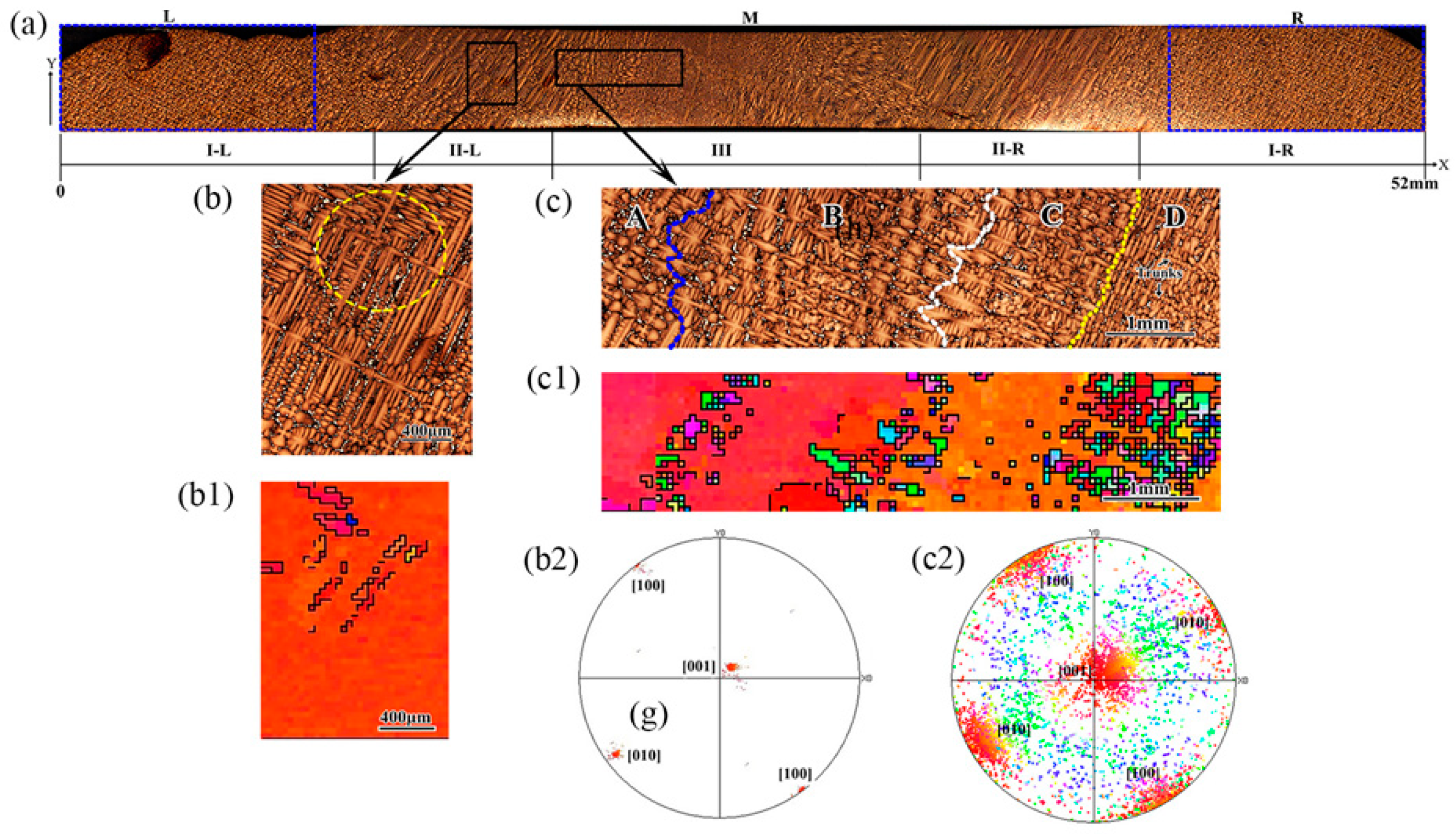
3.1. Dendrite Evolution in the Rejoined Platform

The dendritic structure of platform 3 in the XY plane is shown in Figure 2. Compared to platforms 1 and 2, the characteristics of the defects in platform 3 were most obvious, which was taken as an example to investigate the formation of stray grains in the rejoined platforms. For ease of expression, the platform was divided into three regions, marked as left side (L), middle region (M), and right side (R). According to the growth morphology of the dendrites, the platform was divided into three regions: I, II, and III.
In the regions L and R, the original primary dendrite arms grew regularly and the secondary dendrites formed a two-dimensional cruciform structure. With the dendrites growing into region M, the cruciform dendrites remained until the end of region I (I-L and I-R). Starting from region II (II-L and II-R), long secondary dendrites formed on the outside of the platform. This was because of the lateral growth of the secondary dendrites caused by lateral heat dissipation. Furthermore, some misorientation grains occurred in region II, and their size was comparable with that of the surrounding tertiary dendrites, as shown in the enlarged view in Figure 2b and its EBSD scan in Figure 2(b1). As seen the pole figure in Figure 2(b2), the orientations of these grains were close, all deviating, but being distributed around [001]. When the dendrites continued to grow into region III, the long secondary branches still existed but became thinner, and a lot of grains with various sizes formed, as shown in the enlarged view in Figure 2c.
Combining the metallograph in Figure 2c and its EBSD scan in Figure 2(c1), it can be seen that there were four stages in region III: (1) in region A, there were no broken dendrites, but thinner secondary branches; (2) in region B, small-scale broken tertiary dendrite arms appeared first, followed by a stable region, and the orientation of the trunks was unchanged, as shown in the red region in Figure 2(c1); (3) in region C, the broken branches appeared for the second time, and were also followed by a stable region. However, there was a slight deviation in their orientation, as shown in the orange region in Figure 2(c1); and (4) in region D, almost all the tertiary dendrite arms detached from their parent dendrites, and their orientation was deviated according to the pole figure in Figure 2(c2), in which the corresponding red color gradually turned orange. This meant that there were many broken branches and their orientation had seriously deviated from the main trunks. From then on, the integrity of the single crystal was destroyed completely. There was no doubt that these misorientation grains were stray grains.
From the EBSD scan in Figure 2c, it is shown that the orientations of these detached tertiary grains were different from each other, but they were from the same trunks (the red or orange area in Figure 2c). Meanwhile, the pole figure in Figure 2(c2) displayed that the orientation distribution of the test region was dispersed, but around the trunks (close to the [001] direction), and only a few grains deviated seriously, as shown by the green and blue dots in Figure 2(c2). In addition, the orientation transition of the trunks was from the red to orange position, which indicated that the long secondary dendrites could have been deformed. In other words, the orientation deviation was gradual rather than abrupt. Thus, it can be seen that the secondary dendrites deformed during growth, then their derived tertiary dendrites detached from the mother branches and underwent local torsion, resulting in disorientation.
In order to further confirm the dendrites’ evolution, the formation of fragments, and the dendrite deformation in the rejoined platforms, a metallographic test and EBSD measurements were performed on the longitudinal section (parallel to plane XZ) of platform 3, as shown in Figure 3. Similar to the dendritic evolution within the transversal surface, in regions L and R, the primary dendrites were arranged neatly like branches. As dendrites gradually grew into the middle region of the platform, the arrangement of the dendrites deteriorated. At first, there was a small number of detached dendrites, but later, a large number of broken dendrites appeared. In other words, the number of broken branches significantly increased as the dendrites gradually grew into the platform. Beyond that, another phenomenon, dendrite deformation, was found in the longitudinal section of the platform, as shown in Figure 3a. The red dashed line in Figure 3a is the growth path of the deformed dendrites. Figure 3(a1) and Figure 3(a2) are the EBSD scan image and polar diagram at the corresponding position, respectively. From these figures, it can be seen that the orientation of the main trunks gradually changed, corresponding to the color region in the figures from purple to yellow. This further verifies the existence of dendritic deformation. Finally, a grain boundary formed at the convergence interface, as shown by the yellow dashed line in Figure 3b and its EBSD scan (Figure 3(b1)). However, the grain boundary was closer to the left side of the platform. This might have been related to the original orientation of the dendrites on both sides and the competitive growth between them. In addition, all the fragments distributed along the deformed dendrite (Figure 3a) were located at the intersection, as shown in Figure 3c and its EBSD scan in Figure 3(c1).

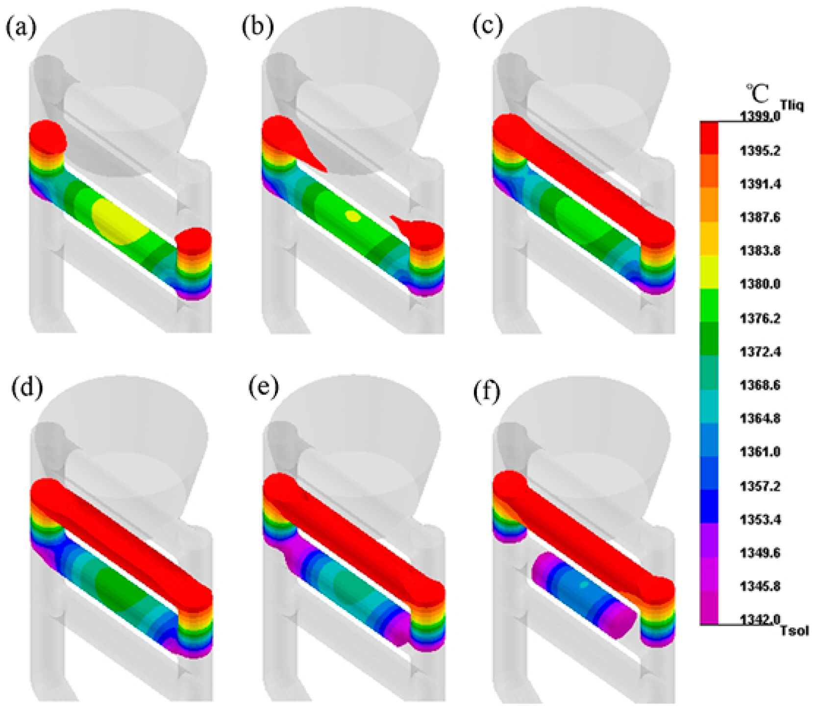
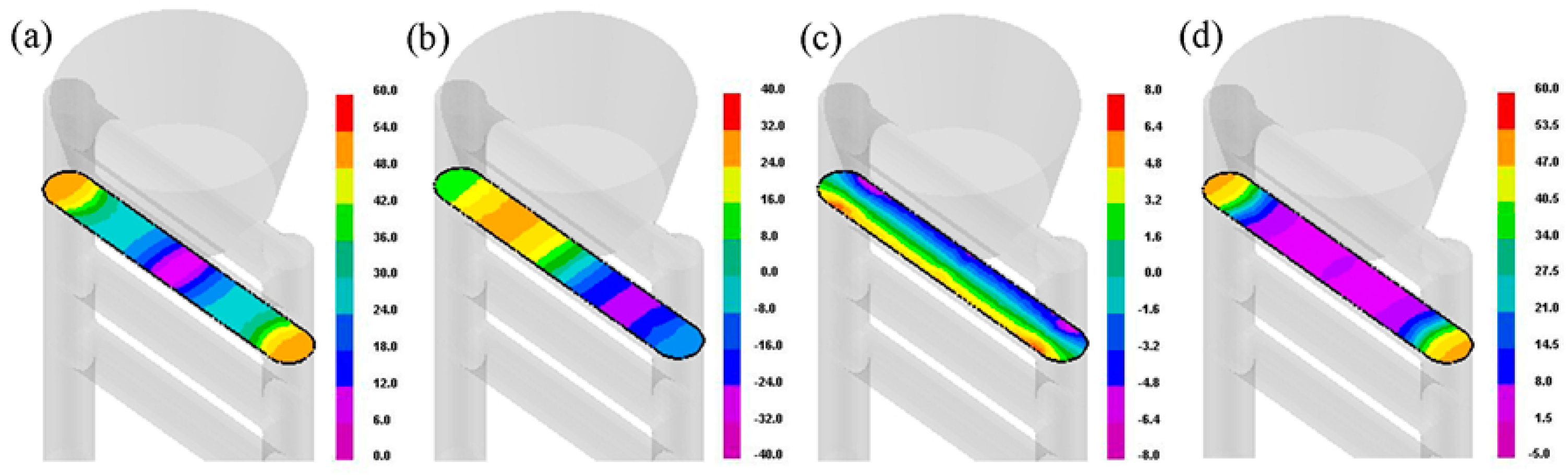
3.2. Finite Element Simulation

Based on the numerical simulation, the shapes of the isotherm in the mushy zone of the rejoined platform with the advancing of the solidification interface were predicted, as shown in Figure 4. It was found that the shapes of the isotherm varied at different times. Firstly, the temperature on both sides of the platform was lower than liquidus (1342 °C) and the interface slightly tilted towards the platform, as shown in Figure 4a. Further withdrawal of the mold resulted in shifting the liquidus isotherm into the platform, as shown in Figure 4b. Then, the interface became a symmetrical sloping groove, as shown in Figure 4c,d. This meant that the lateral heat extraction was enhanced in the platform and this inference was confirmed by the simulation results of the thermal gradient (Figure 5). Finally, directional solidification was completed on the top side of the platform, as shown in Figure 4e,f.
Figure 5 shows the simulation results of the total thermal gradient and the components in three directions of the rejoined platform. As seen from this figure, the total thermal gradient gradually decreased from both sides to the middle region (Figure 5a), the thermal gradients along directions X and Y fluctuated (Figure 5b,c), and the thermal gradient along the Z direction was the lowest in the middle region of the platform (Figure 5d). Thus, it can be seen that the lateral thermal gradients (directions X and Y) were higher but fluctuating. The simulation results of the solidification rate also exhibited similar laws, as shown in Figure 6.

4. Discussion

Based on the above metallographic images, the existence of dendrite trunks meant that initial nucleation could be excluded. Further analysis of the EBSD test results showed that the broken branches in the middle region of the rejoined platforms could have been the result of dendrite fragmentation. The formation mechanism of these defects is discussed below.
As we know, the formation of microstructure and all potential defects during directional solidification are dependent on the local thermal condition, specifically, the thermal gradient and solidification rate [9,28]. Furthermore, the solute diffusion at the solid–liquid interface is also a critical factor affecting the evolution of dendritic structures [29,30,31]. In other words, there are three most concerned factors in the analysis of dendrite fragmentation: the thermal gradient, solidification rate, and solute enrichment. Meanwhile, previous studies have demonstrated that this could not involve a significant detachment of dendrites under steady-state conditions of growth rate and temperature gradient [32], but detachment could be induced with fluctuations in the solidification rate, particularly with deceleration [20,33], possibly preceded by acceleration [34]. Actually, dendrite growth is a three-dimensional process, and a change in growth condition in three directions (X, Y, and Z) is not synchronous, caused by the complex geometry. Therefore, fluctuations of the thermal conditions in any direction can lead to differences in microstructure and dendritic morphology.
In this experiment, the developed secondary dendrites in the platform were caused by good lateral heat dissipation conditions, which could be seen from the simulation results for the thermal gradient in Figure 5. After that, the local detached dendrites occurred firstly in region II (Figure 2b), and finally, a large amount of broken dendrites appeared in region III (Figure 2c), which could be divided into four stages. Based on the EBSD results, these defects could be classified as stray grains. In fact, their formation mechanisms were very complex and different in each region. Therefore, these should be discussed, respectively.
In region II, the total thermal gradient (Figure 5a) and total solidification rate (Figure 6a) were approximately constant. This meant that the local thermal condition was steady and was detrimental to the detachment of the dendrites. However, there were local tertiary dendrite fragments on the long secondary branches, as shown in Figure 2b. As mentioned earlier, obvious lateral growth was induced by the severe lateral heat extraction, and dendrites can grow regularly under stable conditions. In this sample, the inclined solid–liquid interface (Figure 4) and high lateral temperature gradient (Figure 5) in the platform contributed to the inevitable lateral growth in region II (II-L and II-R in Figure 2a). As the solidification front advanced, the secondary arms with severe lateral growth grew, ripened, and coarsened. During the earlier stages of the ripening, the roots or nodes became necked because of excess radial solute rejection from all the surrounding branches. As demonstrated in previous studies [35], fragmentation can occur naturally during coarsening or due to recalescence from eutectic solidification. Consequently, the tertiary branches around the crisscross might have been subjected to an enrichment of the solute in the pockets and detached from their attaching roots first, as shown by the fragments in the yellow dashed circle in Figure 2b. In fact, this could also have been the main reason for the distribution characteristics of the fragments in Figure 3. Thus, the formation mechanism of the broken branches in this region was similar to the research results of Ma et al. [16] and Wang et al. [18]. On the one hand, the roots of the tertiary dendrites were weak during the coarsening process of the surrounding dendrites, and on the other hand, the recalescence upon the sudden release of latent heat might have played a very important role, which ultimately led to small-scale fragments.
In region III, the thermal gradient (Figure 5a,b) and solidification rate (Figure 6a,b) fluctuated many times. As is known, each fluctuation would cause changes in the dendrite spacing and there was a transition for the dendrites to adjust. Previous studies have shown that this adjustment in dendrite spacing may lead to a lag in the thermal response, which might cause local solute pileup and eventually lead to crystal fragments [21,35,36]. This is why there were three regions of secondary dendrite fragments in the platform, as shown regions B, C, and D in Figure 2c. Furthermore, the shape of these regions was close to the solidification interface. As the solidification interface continued to move forward, the secondary branches grew regular again, as shown by the trunks in Figure 2c. However, due to the increase in the solidification rate in the X direction (Figure 5b), the secondary branches here were thinner compared to region II. Meanwhile, an accumulation of the solute was reinforced continuously, which would cause the solidus temperature to decrease [37]. Furthermore, the local torsion of the detached branches could be related to the stress that originated from the solidification process [38]. Consequently, almost all the tertiary arms (Figure 2c and Figure 3c) detached from their parent branches. However, fragmentation occurred in the mushy zone, when the dendritic trunks had already formed, and the broken branches had no space to move or drift away, so only deflected or rotated around themselves. Thus, their orientations were random but their positions were unchanged. Eventually, the mosaic structure was retained in the solidification microstructure. As for the dendrite deformation, this was caused by the solidification shrinkage stress, as analyzed by the author in a previous study in reference [27]. Recently, Yang et al. [39] combined the cellular automaton-finite volume approach with the displacement-based finite element method to simulate dendrite growth and flow-induced deformation in an Al-4.5 wt%Cu alloy, in order to reveal the stress evolution during dendritic growth. It was found that dendrites could undergo visible mechanical bending under stress, which further confirms our speculation and analysis on dendritic deformation.

5. Conclusions

In the present research, the origin of stray grains in rejoined platforms was investigated using experiments and the finite element method. In Ni-based single-crystal superalloy, the stray grains from dendritic fragmentation were first determined and their possible formation mechanism was discussed. The reasons for the formation of the fragments were not entirely the same in different regions, as there were differences in the thermal fields and growth conditions of the dendrites. In general, the detachment of the tertiary arms was mainly caused by the solute enrichment at their roots and the latent heat, while the secondary fragments might have been related to the lag of the dendrite spacing adjustment caused by the fluctuation of the temperature field (especially the temperature gradient and solidification rate), with solute enrichment being the most fundamental reason for this. Therefore, the fragments had different characteristics in different regions with fluctuations. Additionally, dendritic deformation defects were quite common in the rejoined platform, which were caused by solidification shrinkage stress. These defects would damage the integrity and properties of single crystals. There may be a risk of growth during heat treatment, and this would further damage the properties of the alloy. Therefore, their growth mechanism and control measures will be the focus of our attention in the future. Based on previous research results, measures such as controlling the solidification parameters, adjusting the casting structure, and adding auxiliary structures may make progress in reducing solidification defects.

Author Contributions

Conceptualization, L.L., W.Y. and M.H.; methodology, W.Y. and M.H.; validation, C.C., H.J. and M.H.; investigation, C.C., H.J. and M.H.; resources, L.L., W.Y. and M.H.; data curation, W.Y. and M.H.; writing—original draft preparation, M.H.; writing—review and editing, M.H.; funding acquisition, M.H. All authors have read and agreed to the published version of the manuscript.

Funding

This research was funded by National Natural Science Foundation of China (521001130); Natural Science Basic Research Program of Shaanxi (2021JQ-604, 2021JM-403); Scientific Research Program of Shaanxi Provincial Department of Education (21JC027).

Data Availability Statement

The raw/processed data required to reproduce these findings cannot be shared at this time due to technical or time limitations. They will be shared upon request.

Conflicts of Interest

The authors declare no conflict of interest.

References

  1. Reed, R.C. The Superalloys Fundamentals and Applications; Cambridge University Press: Cambridge, UK, 2006. [Google Scholar]
  2. Wang, Z.; Li, J.; Liu, S.; Zhao, J.; Wang, X.; Yang, W. Investigation on freckle formation of nickel-based single crystal superalloy specimens with suddenly reduced cross section. J. Alloys Compd. 2022, 918, 165631. [Google Scholar] [CrossRef]
  3. Yang, Q.; Zhu, X.; Wang, F.; Ma, D.; Wu, J. A study of sliver in C-shaped grain selectors during investment casting of single-crystal superalloy. Metals 2023, 13, 1102. [Google Scholar] [CrossRef]
  4. Xia, H.; Yang, Y.; Feng, Q.; Xu, Q.; Dong, H.; Liu, B. Generation mechanism and motion behavior of sliver defect in single crystal Ni-based superalloy. J. Mater. Sci. Technol. 2023, 137, 232–246. [Google Scholar] [CrossRef]
  5. Yang, Z.; Liu, C.; Hu, S.; Zheng, S.; Luo, Y.; Dai, S. Influence of platform position on stray grain nucleation in Ni-based single-crystal dummy blade clusters. China Foundry 2021, 18, 442–449. [Google Scholar]
  6. Liu, Z.; Miao, K.; Lian, W.; Lu, Z.; Li, D. Elimination of the stray grain defects of single crystal blade by variable wall thickness sased on integral ceramic mold. Metals 2022, 12, 1832. [Google Scholar]
  7. Ren, N.; Li, J.; Wang, B.; Zeng, L.; Xia, M.; Li, J. Design of variable withdrawal rate for superalloy single-crystal blade fabrication. Mater. Des. 2021, 198, 109347. [Google Scholar] [CrossRef]
  8. Vehn, M.M.T.; Dedecke, D.; Paul, U.; Sahm, P.R. Undercooling related casting defects in single crystal Ni-based superalloy. In Superalloys 1996; Kissinger, R.D., Deye, D.J., Anton, D.L., Cetel, A.D., Nathal, M.V., Pollock, T.M., Woodford, D.A., Eds.; TMS: Pittsburgh, PA, USA, 1996; pp. 471–479. [Google Scholar]
  9. Wang, W.; Kermanpur, A.; Lee, P.D.; McLean, M. Simulation of dendritic growth in the platform region of single crystal superalloy turbine blades. J. Mater. Sci. 2003, 38, 4385–4391. [Google Scholar]
  10. Bussac, A.D.; Gandin, C.A. Prediction of a process window for the investment casting of dendritic single crystals. Mater. Sci. Eng. A 1997, 237, 35–42. [Google Scholar] [CrossRef]
  11. Ma, D.; Xu, W.; Xu, F.; Wei, J.; Zhang, H. Comparative investigation of the undercooling capacity and single-crystal castability of some Ni-based superalloys. Crystals 2023, 13, 57. [Google Scholar] [CrossRef]
  12. Zhang, X.; Zhou, Y.; Jin, T.; Sun, X.F. Study on the tendency of stray grain formation of Ni-based single crystal superalloys. Acta Metall. Sin. 2012, 48, 1229–1236. [Google Scholar] [CrossRef]
  13. Meng, X.B.; Li, J.G.; Chen, Z.Q.; Wang, Y.H.; Zhu, S.Z.; Bai, X.F.; Wang, F.; Zhang, J.; Jin, T.; Sun, X.F.; et al. Effect of platform dimension on the dendrite growth and stray grain formation in a Ni-base single-crystal superalloy. Metall. Mater. Trans. A 2013, 44, 1955–1965. [Google Scholar] [CrossRef]
  14. Li, Y.; Liu, L.; Huang, T.; Wang, H.F.; Zhang, J.; Fu, H.Z. Multi-scale characterization of stray grain in the platform of nickel-base single crystal turbine blade. Vacuum 2016, 131, 181–187. [Google Scholar]
  15. Zhou, Y. Formation of stray grains during directional solidification of a nickel-based superalloy. Scr. Mater. 2011, 65, 281–284. [Google Scholar]
  16. Ma, D.; Bührig-Polaczek, A. Application of a heat conductor technique in the production of single-crystal turbine blades. Metall. Mater. Trans. B 2009, 40, 738–748. [Google Scholar] [CrossRef]
  17. Hao, H.; Jiang, W.; Xie, G.; Zhang, G.; Lu, Y.; Zhang, J.; Lou, L. Microstructure and grain orientation evolution of a specially shaped shroud during directional solidification process. Prog. Nat. Sci. Mater. Int. 2013, 23, 211–215. [Google Scholar] [CrossRef] [Green Version]
  18. Wang, F.; Wu, Z.; Huang, C.; Ma, D.; Jakumeit, J.; Bührig-Polaczek, A. Three-dimensional dendrite growth within the shrouds of single crystal blades of a Nickel-based superalloy. Metall. Mater. Trans. A 2017, 48, 5924–5939. [Google Scholar] [CrossRef]
  19. Sun, D.; Liu, L.; Huang, T.; Yang, W.; Li, Y.; Yue, Q.; Zhang, J.; Fu, H. Insight of the dendrite deformation in Ni-based superalloys for increased misorientation along convergent boundaries. Prog. Nat. Sci. Mater. Int. 2018, 28, 489–495. [Google Scholar] [CrossRef]
  20. Yasuda, H.; Ohnaka, I.; Kawasaki, K.; Sugiyama, A.; Ohmichi, T.; Iwane, J.; Umetani, K. Direct observation of stray crystal formation in unidirectional solidification of Sn Bi alloy by X-ray imaging. J. Cryst. Growth 2004, 262, 645–652. [Google Scholar]
  21. Mathiesen, R.H.; Arnberg, L. Stray crystal formation in Al-20wt.% Cu studied by synchrotron X-ray video microscopy. Mater. Sci. Eng. A 2005, 413–414, 283–287. [Google Scholar]
  22. Huo, M.; Liu, L.; Yang, W.; Sun, D.; Hu, S.; Zhang, J.; Fu, H. Formation of slivers in the extended cross-section platforms of Ni-based single crystal superalloy. Adv. Eng. Mater. 2018, 20, 1701189. [Google Scholar]
  23. Miller, J.D.; Pollock, T.M. The effect of processing conditions on heat transfer during directional solidification via the bridgman and liquid metal cooling processes. Metall. Mater. Trans. A 2014, 45, 411–425. [Google Scholar] [CrossRef]
  24. Gao, S.F.; Liu, L.; Wang, N.; Zhao, X.B.; Zhang, J.; Fu, H. Grain selection during casting Ni-base, single-crystal superalloys with spiral grain selector. Metall. Mater. Trans. A 2012, 43, 3767–3775. [Google Scholar]
  25. Wang, N.; Liu, L.; Gao, S.; Zhao, X.; Huang, T.; Zhang, J.; Fu, H. Simulation of grain selection during single crystal casting of a Ni-base superalloy. J. Alloys Compd. 2014, 586, 220–229. [Google Scholar] [CrossRef]
  26. Brundidge, C.L.; Miller, J.D.; Pollock, T.M. Development of dendritic structure in the liquid-metal-cooled, directional-solidification process. Metall. Mater. Trans. A 2011, 42, 2723–2732. [Google Scholar] [CrossRef]
  27. Huo, M.; Liu, L.; Yang, W. Dendrite deformation in the rejoined platforms of Ni-based single crystal superalloys. Adv. Eng. Mater. 2023; early view. [Google Scholar] [CrossRef]
  28. Miller, J.D.; Pollock, T.M. Stability of dendrite growth during directional solidification in the presence of a non-axial thermal field. Acta Mater. 2014, 78, 23–36. [Google Scholar] [CrossRef]
  29. Zhang, Y.; Zhou, J.; Yin, Y.; Ji, X.; Shen, X.; Guo, Z. Study on the solutal convection during dendrite growth of superalloy under directional solidification condition. J. Mater. Res. Technol. 2023, 23, 3916–3927. [Google Scholar] [CrossRef]
  30. Zhang, H.; Wu, M.; Rodrigues, C.M.G.; Ludwig, A.; Kharicha, A.; Rónaföldi, A.; Roósz, A.; Veres, Z.; Svéda, M. Dendrite fragmentation mechanism under forced convection condition by rotating magnetic field during unidirectional solidification of AlSi7 alloy. Acta Mater. 2022, 241, 118391. [Google Scholar]
  31. Ren, N.; Panwisawas, C.; Li, J.; Xia, M.; Dong, H.; Li, J. Solute enrichment induced dendritic fragmentation in directional solidification of nickel-based superalloys. Acta Mater. 2021, 215, 117043. [Google Scholar] [CrossRef]
  32. Hansen, G.; Liu, S.; Lu, S.; Hellawell, A. Dendritic array growth in the systems NH4Cl-H2O and [CH2CN]2-H2O: Steady state measurements and analysis. J. Cryst. Growth 2002, 234, 731–739. [Google Scholar] [CrossRef]
  33. Liu, S.; Lu, S.Z.; Hellawell, A. Dendritic array growth in the systems NH4Cl-H2O and [CH2, CN]2-H2O: The detachment of dendrite side arms induced by deceleration. J. Cryst. Growth 2002, 234, 740–750. [Google Scholar] [CrossRef]
  34. Peng, P.; Li, X.Z.; Li, J.G.; Su, Y.Q.; Guo, J.J.; Fu, H.Z. Detachment of secondary dendrite arm in a directionally solidified Sn-Ni peritectic alloy under deceleration growth condition. Sci. Rep. 2016, 6, 27682. [Google Scholar] [CrossRef] [PubMed] [Green Version]
  35. Li, B.; Brody, H.D.; Kazimirov, A. Real-time observation of dendrite coarsening in Sn-13%Bi alloy by synchrotron microradiography. Phys. Rev. E 2004, 70, 062602. [Google Scholar] [CrossRef] [PubMed]
  36. Kurz, W.; Rappaz, M.; Trivedi, R. Progress in modelling solidification microstructures in metals and alloys. Part II: Dendrites from 2001 to 2018. Int. Mater. Rev. 2021, 66, 30–76. [Google Scholar] [CrossRef]
  37. Yang, W.; Yu, H.; Wang, J.; Cai, C.; Xu, Z.; Li, S.; Liu, F.; Yang, G. Application of dendrite fragmentation to fabricate the homogeneous dispersed structure in undercooled Cu-Co immiscible alloy. J. Alloys Compd. 2011, 509, 9675–9678. [Google Scholar] [CrossRef]
  38. Liu, F.; Cai, Y.; Guo, X.F.; Yang, G.C. Structure evolution in undercooled DD3 single crystal superalloy. Mater. Sci. Eng. A 2000, 291, 9–16. [Google Scholar]
  39. Yang, L.; Ren, N.; Panwisawas, C.; Li, J.; Xia, M.; Dong, H.; Li, J. Melt flow-induced mechanical deformation of dendrites in alloy solidification: A coupled thermal fluid—Solid mechanics approach. J. Mater. Res. Technol. 2023, 25, 4094–4109. [Google Scholar] [CrossRef]
Figure 1. Schematic of the sample assembled with a spiral grain selector (a) and the FEM mesh model of the casting system (b).
Metals 13 01470 g001
Figure 2. Transversal (parallel to plane XY) microstructures of the platform 3 (a), enlarged view of the stray grains in the region M (b,c), their EBSD scans (b1,c1), and their polar diagrams (b2,c2).
Metals 13 01470 g002
Figure 3. Longitudinal (parallel to plane XZ) microstructure of the platform 3 (a), EBSD scan of the region with fragments (a1), and its polar diagram (a2), enlarged views of different regions (b,c), and their corresponding EBSD scans (b1,c1).
Metals 13 01470 g003
Figure 4. The shape of isotherm in mushy zone of the rejoined platform with the advancing of solidification interface, (a) t = 1014 s, (b) t = 1024 s, (c) t = 1034 s, (d) t = 1044 s, (e) t = 1054 s, (f) t = 1064 s.
Metals 13 01470 g004
Figure 5. The total thermal gradient (a) and components in three directions of the rejoined platform (b) lateral thermal gradient (along X direction) and (c) along Y direction, (d) axial thermal gradient (along Z direction) (°C/cm) [27].
Metals 13 01470 g005
Figure 6. Contour plots of total solidification rate (a) and the solidification rates in X direction (b), in Y direction (c), and in Z direction (d).
Metals 13 01470 g006
Table 1. Nominal compositions of DD6.
NiCrCoMoWTaReNbAlHfC
Bal.4.39287.520.55.60.10.006
Disclaimer/Publisher’s Note: The statements, opinions and data contained in all publications are solely those of the individual author(s) and contributor(s) and not of MDPI and/or the editor(s). MDPI and/or the editor(s) disclaim responsibility for any injury to people or property resulting from any ideas, methods, instructions or products referred to in the content.

