Abstract
Compared with other forming processes, Pilger cold rolling exhibits unique process characteristics and a simple production method, making it highly advantageous in terms of high-precision, high-strength, and poor-plasticity alloys. Among them, the design parameters of the rolling mill play a significant role in the rolling results, with the key design parameters being the hole opening angle θ and the hole gap ΔK. In this study, a numerical simulation model for cold rolling an AZ31B magnesium alloy with variable cross-section three-roll Pilger cold rolling was established, and finite element simulation analysis was employed to obtain the comprehensive performance impact law of key design parameters on the cold-rolled AZ31B magnesium alloy. It can be concluded that when the hole opening angle is 10° and the hole gap is 1.2 mm, the equivalent stress and equivalent plastic strain of the billet reach a minimum, and the surface precision is excellent.
1. Introduction
Cold rolling is one of the primary methods for producing seamless tubes today. Compared to processing methods such as hot rolling, hot extrusion, and cold extrusion, cold rolling has the advantages of low processing costs, high production efficiency, and better utilization of material properties [1]. As a piece of key equipment in cold rolling forming, the design of the roll pass is one of the most critical tasks in the design of cold rolling mills, as it directly affects the rolling precision and quality of the finished tubes.
In view of the importance of the key design parameters of the roll hole pattern and key process parameters on the impact of accuracy, from the first Pilger cold rolling mill in 1952, the relevant research workers have been committed to Pilger cold rolling tube roll hole pattern design optimization. Pociecha [2] used computer simulation technology to simulate the cold rolling tube manufacturing process and verified the accuracy of the simulation results. Hideaki [3] investigated the effects of process parameters, including feed rate, rolling speed, and roll angle, on the cold rolling of stainless-steel tubes and zirconium alloy tubes. He [4] investigated the effects of feed rate and wrap angle on the bonding layer and ellipticity of bimetallic composite tubes. Wei [5] studied the evolution of residual stresses in billets during the cold rolling process under different process parameters. Wang [6] employed the elastoplastic, large deformation, and contact nonlinear finite element method to analyze the influencing factors on the diameter and wall thickness accuracy of finished steel tubes. Nalawade [7] conducted optimization analysis on the depth of roll groove, cone angle, and radius of fillet using FORGE finite element software. He [8] simulated the Pilger rolling of zirconium alloy cladding tubes by establishing a 3D finite element model. The results showed different stress-strain states at the groove edge and groove bottom during the rolling process, resulting in significant shear deformation. Wei [9] proposed an analysis model that can predict the shape and stress distribution of billets during the rolling process, thereby reducing the formation of defects. Wang [10] conducted a comprehensive numerical simulation to analyze the variation patterns of important process parameters and finished dimensions during the Pilger cold rolling process. They determined the effects of feed rate and wrap angle on key mechanical parameters during the cold rolling process. Zhao [11] used the finite element method to analyze the effects of key factors such as rolling speed and feed rate on the rolling process. Miguel [12] analyzed the shape of steel tubes, the distribution of stress-strain fields, and the transverse wall thickness of rolled products under different roll groove designs using the finite element method. Goncharuk [13] proposed methods to improve the dimensional accuracy of pipes and the quality of their inner and outer surfaces using computer physics modeling techniques. Chu [14] compared numerical simulation data of the tube rolling process under different process parameters. The results indicated that the rolling force, maximum equivalent stress of tube deformation, average residual stress, and spring back of the tube deformation section all varied with changes in the process parameters. Zhao [15] provided a method for determining the key parameters of roll skew angle and roll groove profile curve. Dekhtyarev [16] employed a novel method to design the transverse shape of the groove in order to improve the dimensional accuracy of the finished pipes. Wang [17] proposed a method that combines parameterized design with groove profile design theory, simplifying the process of roll groove design and improving the accuracy of the design results. Zhou [18] designed a new roll groove profile based on the deformation characteristics of the tube during rolling. Lin [19] employed a method of distributing the top extension coefficient of roll groove profiles to design the continuous rolling mill roll groove. Although it achieved high wall thickness accuracy of the rolled steel tubes, the design process required multiple iterations of modifying process parameters. Yin [20] optimized the roll groove profiles based on the consideration of stress distribution.
This paper focuses on the variable cross-section three-roll Pilger cold rolling rolls and specifically investigates the range of values for the roll pass hole opening angle and hole gap. The study analyzes and compares the effects of different hole opening angles and hole gaps on the force-energy parameters and precision in the reduction zone of the product. It addresses the deficiencies in the research of key design parameters on the comprehensive performance of the product, providing a theoretical basis and simulation foundation for determining the design parameters of cold-rolled tubes.
2. Design Formula for Roll Cross-Section
Figure 1 shows a schematic diagram of the roll cross-section.
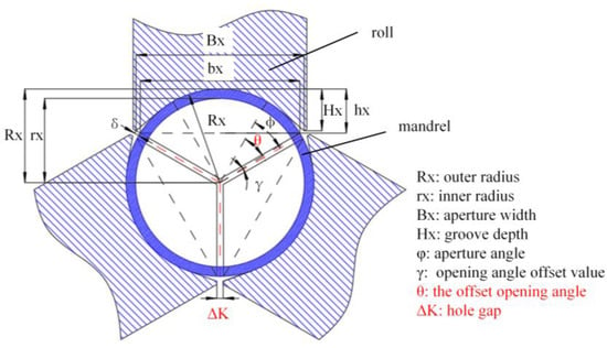
Figure 1.
Schematic diagram of roll cross-section.
2.1. Distance from the Bottom of the Groove to the Center Line of the Pipe Billet
After the groove of the roll is unfolded, it forms a smooth curve, as shown in Figure 2. Based on the different regions of the groove, it can be divided into the reduction zone curve, the wall reduction zone curve, and the pre-finishing zone curve. In the finishing zone, the distance from the groove bottom to the centerline of the billet no longer changes. Therefore, the unfolded groove in the finishing zone is a straight line, with the same value as the final cross-section data of the pre-finishing zone. To reduce the computational load, conventional calculation methods usually divide it into seven sections or nine–ten sections [21], with several additional points inserted in each section. This approach allows the groove curve to be divided into dozens of sections, enabling a relatively accurate calculation. To further improve accuracy, the segmentation method divides it into one section per degree. For larger-sized rolls, this design method is more precise. Additionally, with the aid of computer-aided design calculations, the computational load, which is typically high, can be neglected.
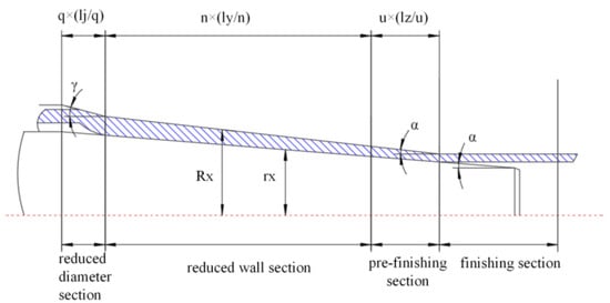
Figure 2.
Schematic diagram of the unfolded profile of the roll groove.
- Reduced diameter section [22]
: Distance from the requested reduced diameter section to the rolling starting position.
Dividing the reduced section into q sections, with the contact section with the depressed section (end of the reduced section/beginning of the depressed section) as 0 section. In this section, , . On the far left (reduced section starts with section q), , .
- 2.
- Reduced wall section
D: Outside diameter of the finished tube
S: Wall thickness of the finished tube
lyx: the distance from the section of the pressed down section to the start of the sizing section. Let the pressed down section be divided into n sections, the section at the beginning of the pressed down section is a 0 section, and the distance lyx = lq, , …… …… .
λSΣ: total elongation factor, λSΣ =
ΔS: wall thickness increment during the reduced diameter section, ΔS = (0.05~0.06)ΔDj
: moving coordinates, greater than 0 and less than 1, x is the distance from the reduced wall section to the beginning of the reduced wall section, , …… …… .
n2: coefficient, to have a reasonable curvature for the curve on top of the groove, n2 = 0.64.
e: natural constant, e = 2.718281828.
- 3.
- pre-finishing section
The pre-finishing section is divided into u sections and the contact section with the pressed-down section (i.e., the end of the pressed-down section/beginning of the pre-finishing section) is the nth section, in this section , . In the leftmost section (i.e., the beginning section of the finishing section is the n + u section), , .
2.2. Shape Tools Parameters
- Angle of opening
The formula for calculating the hole opening angle after offset, considering the hole gap.
: Angle of opening when not offset, as input value.
γx: Offset due to hole pattern gap.
- 2.
- Width of hole pattern
: Hole gap.
- 3.
- Depth of rolling groove
3. Selection of Key Design Parameters
3.1. Selection of Hole Opening Angle
As one of the key design parameters in the hole pass design, the hole opening angle of the roll pass has a significant impact on the mechanical parameters during the cold rolling process of tubes, particularly for the rolling of difficult-to-deform alloy tubes. It also affects the quality and precision of the finished tubes after rolling.
During the rolling process, the billet not only undergoes axial elongation but also experiences some metal flow in the circumferential direction. Therefore, uneven deformation in the circumferential direction during the rolling process can lead to earing (protrusions at the opening of the billet). If the hole opening angle is chosen too small, it can easily lead to excessive earing. During the subsequent rotation and entry into the rolling process, the earing will be pressed into the billet. The presence of excessive earing exacerbates internal stresses and uneven deformation within the billet, which may result in cracking of the billet. This, in turn, increases the production of substandard products and intensifies the wear of the rolling mill rolls, thereby affecting the service life of the pipe rolling machine. Therefore, in order to avoid the generation of excessive earing during the rolling process, it is necessary to increase the hole opening angle in the direction of the hole width. However, the hole opening angle should not be too large. An excessively large hole opening angle reduces the area of direct contact between the rolling mill and the billet, resulting in reduced axial elongation of the billet and increased width expansion. This leads to a decrease in the dimensional accuracy of the pipes and an increase in the quantity of defective products during the production process, reducing production efficiency and increasing production costs. Therefore, the selection of the hole opening angle has certain practical significance in production.
Based on the relationship between the axial extension force and the circumferential flow force of the billet, in order to ensure better filling of the metal billet into the roll pass without significant earing, the hole opening angle of the roll pass should be less than 40° [23]. Considering the smaller rolling specifications, it was decided to select four angles: 5°, 10°, 15°, and 20°, after comprehensive consideration. The study analyzes the effects of different hole opening angles on the equivalent stress, equivalent plastic strain, and roundness of the finished tube in the reduction zone during the rolling process of the new three-roll Pilger rolling.
3.2. Selection of Hole Gap
In order to ensure that there is no mutual interference during the operation of the rolling mill and due to processing requirements, there needs to be a certain gap between the rolls. The selection of the size of the gap between the rolls is one of the key design parameters in hole design. It has a significant impact on the rolling efficiency of cold-drawn pipes, especially for difficult-to-deform alloy pipes, and the precision of the quality of the finished pipes after rolling.
If the gap between the rolls is chosen too small, it is easy for the earing extruded at the hole opening angle during the rolling mill movement to be sucked in, resulting in more severe burr formation. During the subsequent rotation and entry into the rolling process, the burr will be pressed into the billet, directly leading to the scrapping of the billet. On the other hand, if the gap between the rolls is chosen too large, it will encroach on the volume of the rolls, resulting in a reduced actual working area of the rolls. This causes uneven stress distribution in the circumferential direction of the pipe, potentially leading to cracking and other issues. Moreover, it also increases the wear on the region of the hole opening angle, damaging the mold and increasing production costs. Therefore, selecting an appropriate gap between the rolls is beneficial for improving production accuracy, rolling efficiency, and equipment lifespan.
This paper takes the rolling of small-diameter thin-walled tubes as the object of simulation. Depending on the size of the rolling specification, the hole gap is taken as 0.8 mm, 1.2 mm, 1.6 mm, and 2 mm to analyze the effect of different hole gaps on the equivalent stress and equivalent plastic strain of the reduced section and the roundness of the finished tube during the new three-roll Pilger rolling process.
4. Simulation Model Building
4.1. Model Building
The Pilger cold rolling process consists of a feeding mechanism, an entry mechanism, a rolling mechanism, and an exit mechanism. The main rolling operation takes place in the rolling mechanism, where the rolls and mandrel interact to achieve the rolling effect. However, establishing a complete model requires complex modeling and intricate contact settings, which significantly increase simulation time. In order to obtain relatively reasonable simulation data within a relatively short simulation time, it is necessary to simplify the simulation model.
In actual production, the rolls are indirectly driven by the connecting rod, and the reciprocating rotational motion of the rolls is achieved through the meshing of gears and racks. When the rolls complete one full cycle, the entry device drives the billet to rotate and advance. In the simulation, the virtual simulation model is simplified to include the billet, mandrel, rolls, and push block, as shown in Figure 3.
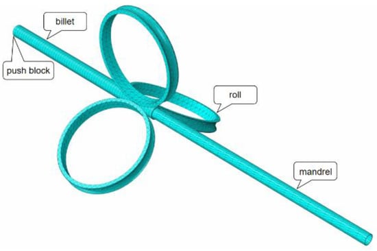
Figure 3.
Finite element model for three-roll Pilger rolling with a variable cross-section.
4.2. Simulation Parameter Setting
This paper utilizes Abaqus simulation software and employs AZ31B magnesium alloy tubes as the simulation object, whose chemical composition is shown in Table 1. AZ31B magnesium alloy performance testing was conducted using GLEEBLE experiments [24], and the specimen dimensions along with its stress-strain curve are illustrated in Figure 4. The material parameters are listed in Table 2.

Table 1.
Chemical composition table of AZ31B magnesium alloy bars (wt%) [25].
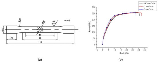
Figure 4.
(a) Tensile sample; (b) Stress-strain curves at different tensile rates.
Table 2.
Parameters of the AZ31B magnesium alloy.
In the simulation setup, the constraint rod is fixed, and the billet and rolls undergo reciprocating rolling. The single-pass rolling feed is set to 10 mm [26]. Considering the presence of a significant amount of lubricant between the rolls and billet, as well as between the billet and the constraint rod during the rolling process, a friction coefficient of 0.1 is applied. The pusher and billet relate to a binding constraint, and no friction coefficient is required, as the pusher can drive the billet forward with rotational movement. Additionally, to simplify the computational task without significantly affecting the simulation results2, the following settings are adopted:
- The mandrel and rolls were set as rigid bodies;
- The influence of inertia forces on rolling was not considered;
- The influence of temperature on rolling was not considered.
The specific parameters for simulation are shown in Table 3.
Table 3.
Simulation parameters.
5. Discussion of Simulation Results
During the rolling process, the three rolls are uniformly distributed circumferentially around the central axis and operate with identical motion patterns. The mechanical variations closely follow their geometric relationship. Therefore, it is possible to analyze a 120-degree region located below one of the rolls, with the remaining 240-degree region exhibiting similar variations. For the selected 120-degree region, fourteen data points were extracted, with seven points on each side (inner and outer), spaced at 30-degree intervals. The first and seventh data points are positioned at the two ends of the selected region, as shown in Figure 5 [27].
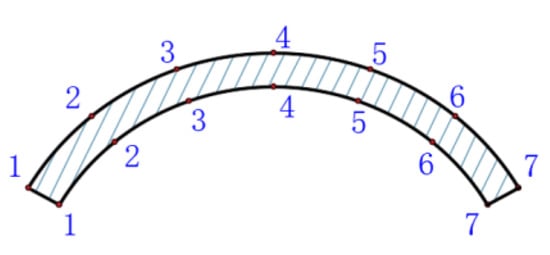
Figure 5.
Selection of data points.
5.1. The Influence of the Hole Opening Angle on Comprehensive Performance
5.1.1. Equivalent Stress under Different Hole Opening Angles
Figure 6 shows the data curves of the equivalent stress on the inner and outer walls of the billet during the wall reduction stage for hole opening angles of 5°, 10°, 15°, and 20°. It can be observed that the curves of equivalent stress for the four different hole opening angles exhibit a similar trend of variation.
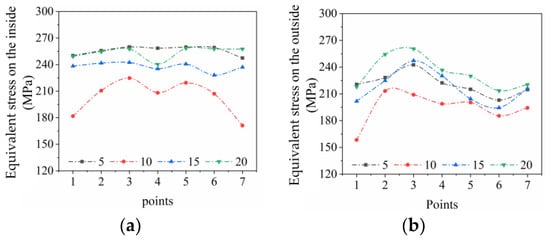
Figure 6.
Data curves of the equivalent stress on the billet during the reduced wall section under different hole opening angles. (a) The inner wall; (b) The outer wall.
On the inner wall of the billet, due to the occurrence of ears and uneven circumferential metal flow during the rotational rolling of the billet, the resulting wall thickness is uneven. One side exhibits ear, leading to higher equivalent stress during rolling on that side. This causes the equivalent stress on the outer wall of the billet to shift towards one side of the symmetrical center (point 3). However, overall, there is still a trend of higher equivalent stress in the middle and lower equivalent stress on both sides.
On the outer wall of the billet, the curve is generally symmetrical about the center of the ridge (point 4). The ridge region of the groove (from point 3 to point 5) exhibits higher equivalent stress at both ends and lower equivalent stress in the middle. In the side regions, there is a trend of lower equivalent stress at both ends and higher equivalent stress in the middle.
Based on the comparison of the four sets of curves, it can be observed that under this rolling specification, the hole opening angle of 10° corresponds to a relatively minimum value of the equivalent stress. Increasing or decreasing the hole opening angle will result in higher values of the equivalent stress.
5.1.2. Equivalent Plastic Strain under Different Hole Opening Angles
Figure 7 shows the schematic curves of equivalent plastic strain data on the inner and outer walls of the billet in the reducing section under different hole opening angles of 5°, 10°, 15°, and 20°.
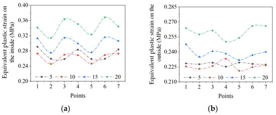
Figure 7.
Equivalent plastic strain data curves of the billet in the reduced wall section under different hole opening angles. (a) The inner wall; (b) The outer wall.
From the equivalent plastic strain data curves of the inner and outer walls in the reducing section, it can be observed that the presence of ears and uneven circumferential metal flow during the rotation and feeding of the billet in the rolling process may result in uneven surfaces. However, overall, it still follows the deformation pattern and remains approximately symmetrical about the centerline. These observations are consistent with the equivalent plastic strain curves. Among the four sets of virtual simulation results, the hole opening angle of 10° yields the minimum equivalent plastic strain. Smaller or larger hole opening angles increase the value of equivalent plastic strain.
5.1.3. Diameter Accuracy under Different Hole Opening Angles
Figure 8 shows the inner and outer diameter curves of the finished pipes after the final sizing stage under different hole opening angles of 5°, 10°, 15°, and 20°. Roundness is an important physical parameter for assessing the dimensional accuracy of the finished pipes. The dimensional data of the inner and outer diameters can visually reflect their roundness. The compliance of the dimensional data of the inner and outer diameters of the finished pipes can be determined based on GB/T 17395-2008 (current standard) pipe dimensions, shape, weight, and permissible deviations.
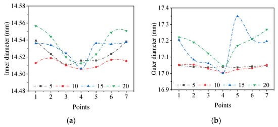
Figure 8.
Different hole opening angles result in varying diameter curves of the finished pipes. (a) The inner diameter; (b) The outer diameter.
From the schematic diagram of the outer diameter dimension data of the finished pipes after the sizing stage, it can be observed that, in terms of the outer diameter, according to the standard GB/T 17395-2008, when the tolerance grade is D4, the diameter tolerance rate is less than ±0.5%. This means that the allowed outer diameter size is 17 ± 0.085 mm. Therefore, only when the hole opening angle is set to 5° and 10°, can the outer diameter dimensions meet the D4 tolerance grade. When the hole opening angle is set to 15° and 20°, some positions of the outer diameter dimensions have exceeded the allowable range limits, which indicates that they are non-conforming products.
From the schematic diagram of the inner diameter dimension data of the finished pipes after the sizing stage, it can be observed that, in terms of the inner diameter, according to the standard GB/T 17395-2008, when the tolerance grade is D4, the diameter tolerance rate is less than ±0.5%. This means that the allowed inner diameter size is 14.5 ± 0.0725 mm. The inner diameter dimensions of the finished pipes under all four hole opening angles meet the standard. Among them, the inner diameter size is more excellent when the hole opening angle is set to 10°.
In conclusion, based on the schematic diagrams of the inner and outer diameter dimension data of the finished pipes, it can be inferred that the choice of hole opening angle has a relatively minor impact on the inner surface accuracy of the finished pipes, but it has a significant impact on the outer surface accuracy. The inner surface, supported continuously by the core rod, is also affected to some extent but still meets the requirements of the national standard. However, excessively large hole opening angles can cause the outer surface dimensions of the pipe blank to exceed the allowed limits, resulting in the production of non-compliant products, reducing the yield of qualified finished pipes, and increasing production costs. Therefore, considering all factors, for this specific rolling specification, selecting a hole opening angle of 10° is the most advantageous and effective choice for achieving the best inner and outer surface accuracy of the finished pipes.
5.2. The Impact of the Hole Gap on Comprehensive Performance
5.2.1. The Equivalent Stress under Different Hole Gaps
Figure 9 depicts the schematic curves of equivalent stress data for the inner and outer walls of the billet in the reduced wall section under different hole gaps of 0.8 mm, 1.2 mm, 1.6 mm, and 2 mm.
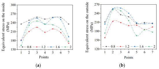
Figure 9.
The data curve of equivalent stress in the reduced wall section of the billet under different hole gaps. (a) The inner wall; (b) The outer wall.
From the curves of equivalent stress for the outer and inner walls in the reduced wall section, it can be observed that the circumferential flow of the metal and the rotational rolling of the billet may result in non-uniformity along the circumference, causing the equivalent stress to deviate from strict symmetry about the central point, which is consistent with the stress variation pattern in the reduced wall section. Among the four sets of virtual simulation results, the hole gap of 1.2 mm corresponds to the minimum value of equivalent stress. Smaller or larger hole gaps would increase the values of equivalent stress.
5.2.2. Different Equivalent Plastic Strain Variations under Various Hole Gaps
Figure 10 shows the data curves of equivalent plastic strain for the inner and outer walls of the pipe billet in the reduction section under different hole gaps of 0.8 mm, 1.2 mm, 1.6 mm, and 2 mm.
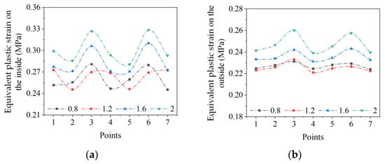
Figure 10.
Different equivalent plastic strain variations of the pipe billet in the reduction section under different hole gaps. (a) The inner wall; (b) The outer wall.
From the data curves of equivalent plastic strain for the outer and inner walls in the reduction section, it can be observed that the equivalent plastic strain is approximately symmetrical about the center of the ridge (point 4). Among the four sets of virtual simulation results, the minimum value of equivalent plastic strain is achieved when the hole gap is set to 1.2 mm. Increasing or decreasing the hole gaps will result in an increase in equivalent plastic strain for both the inner and outer walls of the pipe billet in the reduction section.
5.2.3. Diameter Accuracy under Different Hole Gaps
Figure 11 shows the diameter curves of the finished pipe’s inner and outer surfaces after the finishing section for different hole gaps.
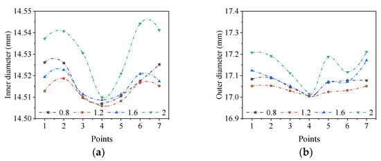
Figure 11.
The diameter curves of the finished pipe under different hole gaps (a) The internal diameter; (b) The outer diameter.
From the schematic diagram of the outer diameter dimension data of the finished pipes after the finishing section, it can be observed that, in terms of the outer diameter, according to the standard GB/T 17395-2008, when the tolerance grade is D4, the diameter tolerance rate is less than ±0.5%. This means that the allowed outer diameter size is 17 ± 0.085 mm. Therefore, only when the hole gap value is set to 1.2 mm, the outer diameter dimensions can meet the D4 tolerance grade. When the hole gaps values are set to 1.6 mm and 2 mm, some positions of the outer diameter dimensions have exceeded the allowable range limits, indicating that they are non-compliant products.
From the schematic diagram of the inner diameter dimension data of the finished pipes after the finishing section, it can be observed that, in terms of the inner diameter, according to the standard GB/T 17395-2008, when the tolerance grade is D4, the diameter tolerance rate is less than ±0.5%. This means that the allowed inner diameter size is 14.5 ± 0.0725 mm. The inner diameter dimensions of the finished pipes under all four hole gaps meet the standard. Comparatively, the hole gap value of 1.2 mm yields a more excellent inner diameter size.
In conclusion, from the schematic diagrams of the inner and outer diameter dimension data of the finished pipes, it can be concluded that the choice of hole gap has a relatively minor impact on the inner surface accuracy of the finished pipes, but it has a significant impact on the outer surface accuracy. However, excessive hole gaps can cause the outer surface dimensions of the pipe blank to exceed the allowed limits, resulting in the production of non-compliant products, reducing the yield of qualified finished pipes, and increasing production costs. Therefore, considering all factors, for this specific rolling specification, selecting a hole gap value of 1.2 mm is the most advantageous and effective choice for achieving the best inner and outer surface accuracy of the finished pipes.
6. Conclusions
- This paper analyzed the simulation experiments and demonstrated that the hole opening angles and hole gaps of the variable cross-section three-roll Pilger cold rolling rolls have a significant impact on the rolling accuracy of magnesium alloy pipes and the force parameters during the rolling process.
- The simulation results indicate that, under this rolling specification, the hole opening angle of 10° yields the relative minimum values of equivalent stress and equivalent plastic strain, resulting in the highest accuracy of the inner and outer surfaces of the rolled product. Similarly, the hole gap of 1.2 mm leads to the relative minimum values of equivalent stress and equivalent plastic strain, resulting in the highest accuracy of the inner and outer surfaces of the rolled product.
- The simulation results demonstrate that selecting excessively large or small hole opening angles and hole gaps can lead to a reduction in rolling accuracy. For different production specifications, corresponding simulation analyses should be conducted to determine suitable hole design parameters. The optimal hole design parameters obtained from the simulation experiments in this paper are only applicable to this specific rolling specification and do not have generalizability. However, they provide a theoretical basis and simulation foundation for determining the design parameters of cold-rolled pipe materials in other specifications.
Author Contributions
Conceptualization, methodology, validation, resources, Y.H. and X.D.; software, formal analysis, data curation, S.L.; investigation, Y.Z.; writing—original draft preparation and writing—review and editing, Y.H. and S.L. All authors have read and agreed to the published version of the manuscript.
Funding
This research was funded by Shanxi Province Science and Technology Major Special Plan “Unveiling and Leading” Project, grant number No: 202101110401009, Shanxi Province Excellent Graduate Innovation Project, grant number No: 2021Y671, National Natural Science Foundation of China, grant number No: 52175353 and Shanxi Province Patent Transformation Special Program Project, grant number No: 202201001.
Institutional Review Board Statement
Not applicable.
Informed Consent Statement
Not applicable.
Data Availability Statement
The data that support the findings of this study are available from the corresponding author upon reasonable request.
Conflicts of Interest
The authors declare no conflict of interest.
References
- Zheng, Z.Q. Fundamentals of Materials Science; Central South University: Changsha, China, 2013. [Google Scholar]
- Pociecha, D.; Boryczko, B.; Osika, J.; Mroczkowski, M. Analysis of tube deformation process in a new pilger cold rolling process. Archiv. Civ. Mech. Eng. 2014, 14, 376–382. [Google Scholar] [CrossRef]
- Abe, H.; Iwamoto, T.; Yamamoto, Y.; Nishida, S.; Komatsu, R. Dimensional accuracy of tubes in cold pilgering. J. Mater. Process. Technol. 2016, 231, 277–287. [Google Scholar] [CrossRef]
- He, Z.L.; Chen, J.X.; Shuang, Y.H.; Gou, Y.J.; Ding, X.F.; Gui, H.L.; Huang, X.M. Effect of Pilger hot-rolling process parameters on bonding layer and ovality of 06Cr19Ni10/0235 bimetal composite pipe. Forg. Stamp. Technol. 2023, 2023, 96–101. [Google Scholar]
- Wei, D.; Chen, Y.; Li, H.; Yang, J. Residual stress evolution and tailoring of cold pilgered Ti-3Al-2.5 V tube. Int. J. Mech. Sci. 2022, 225, 107366. [Google Scholar] [CrossRef]
- Wang, X.K.; Ye, J.D.; Ma, X.; Tian, Q.Q.; Li, X.; Bao, Y. Finite element analysis on steel tube forming process of three-roller continuous rolling. Heavy Mach. 2014, 2014, 51–56. [Google Scholar]
- Nalawade, R.S.; Marje, V.R.; Balachandran, G.; Balasubramanian, V. Effect of pass schedule and groove design on the metal deformation of 38MnVS6 in the initial passes of hot rolling. Sadhana 2016, 41, 111–124. [Google Scholar] [CrossRef]
- He, W.J.; Yuan, G.H.; Luan, B.F.; Wang, L.; Chu, L.H.; Liu, Q. On the Pilger Rolling of Zr-4 Alloy: Finite Element Modeling and Plastic Deformation Behavior. Rare Met. Mater. Eng. 2018, 47, 82–88. [Google Scholar]
- Wei, Z.H.; Wu, C.J. A new analytical model to predict the profile and stress distribution of tube in three-roll continuous retained mandrel rolling. J. Mater. Process. Technol. 2022, 302, 117491. [Google Scholar] [CrossRef]
- Wang, H.Z.; Chu, Z.B.; Li, W.; Xue, Z.Y.; Zhang, D.; Huang, Q.X. Research on Forming Process Parameters and Mechanics of Pilger Cold-Rolled Seamless Steel Tube. Hot Work. Technol. 2019, 48, 88–93. [Google Scholar]
- Zhao, T.Y.; Cai, L.M.; Lu, M.H.; Zhan, J.L.; Zeng, X.J. 3D FEM thermo-mechanical coupling analysis of seamless tube high speed cold rolling. Heavy Mach. 2022, 369, 87–91. [Google Scholar]
- Miguel, A.C.; Marcela, B.G.; Eduardo, N.D. Finite element analysis of steel rolling processes. Comput. Struct. 2001, 79, 2075–2089. [Google Scholar]
- Goncharuk, A.V.; Fadeev, V.A.; Kadach, M.V. Seamless Pipes Manufacturing Process Improvement Using Mandreling. Solid State Phenom. 2021, 6014, 402–407. [Google Scholar] [CrossRef]
- Chu, Z.B.; Xue, Z.Y.; Zhang, D.; Wang, H.Z.; Li, W.; Liu, R.H.; Huang, Q.X. Parameters of cold pilgering of seamless steel tube. J. Iron Steel Res. Int. 2019, 26, 9. [Google Scholar] [CrossRef]
- Zhao, C.J.; Liu, Y.F.; Bai, L.; Wang, N.; Gao, X.; Shuang, Y.H. Stretch reduction of seamless steel tube by skew rolling and its numerical simulation. Metall. Res. Technol. 2016, 113, 307. [Google Scholar] [CrossRef]
- Dekhtyarev, V.S.; Frolov, Y.V.; Tereshchenko, A.A.; Golovchenko, A.P. Comprehensive approach to realizing new technologies for the production of high-precision cold-worked tubes. Metallurgist 2009, 53, 152–157. [Google Scholar] [CrossRef]
- Wang, Q.; Huang, P.; Yi, Y.H. Design and analysis of rolling tool pass based on parameterization. Forg. Stamp. Technol. 2020, 45, 92–100. [Google Scholar]
- Zhou, X.F. Pass design of two-high cold rolling pilger mill. Forg. Stamp. Technol. 2012, 37, 55–58. [Google Scholar]
- Lin, Z.; Wang, Z.H.; Mi, Y.F.; Zhang, L.Z. Pass Development for Φ89 mm 3-roll FOM. Steel Pipe 2022, 51, 42–46. [Google Scholar]
- Yin, Y.H.; Huang, W.; Deng, X.S.; Wu, S.H. Finite element analysis of cold- rolled titanium tube based on Deform-3D. Forg. Stamp. Technol. 2014, 39, 122–126. [Google Scholar]
- Yan, F.F. Pass Design of LG730 Cold-Rolling Pilger Mill and Its Finite Element Simulation in the Rolling-Process. Master’s Thesis, Yanshan University, Qinhuangdao, China, 2015. [Google Scholar]
- Li, L.S. Principles of Plastic Deformation of Steel Pipes; Metallurgical Industry Press: Beijing, China, 1989; Volume 2. [Google Scholar]
- Lu, Y.Q.; Fu, X.C.; Liu, H.W.; Xing, W.J. LD type cold rolling mill roll hole opening angle on the force parameters and the impact of steel pipe accuracy. Steel Pipe 1985, 1985, 1–8. [Google Scholar]
- Xu, C.; Chu, Z.B.; Su, H.; Li, W.; Ma, L.F.; Li, Y.G. AZ31 Magnesium Alloy Solution Treatment Key Process Parameters and Experimental Verification. J. Funct. Mater. 2020, 51, 9159–9165. [Google Scholar]
- Chai, R.X.; Wen, L.M.; Xu, S.Q.; Chi, C.Z.; Fan, Y.D. Testing of mechanical property of AZ31 magnesium alloy extruded tubes. Light Alloy Fabr. Technol. 2006, 2006, 21–23. [Google Scholar]
- Li, W.; Shuai, M.R.; Chu, Z.B.; Wang, H.Z.; Xue, Z.Y. Study on key technology parameter cycle feed range of Pilger cold-rolling pipe mill. J. Plast. Eng. 2019, 26, 279–285. [Google Scholar]
- Xue, Z.Y. Study on Critical Process Parameters in Cold Rolling Process of AZ31 Magnesium Alloy Tube. Master’s Thesis, Taiyuan University of Science and Technology, Taiyuan, China, 2019. [Google Scholar]


Disclaimer/Publisher’s Note: The statements, opinions and data contained in all publications are solely those of the individual author(s) and contributor(s) and not of MDPI and/or the editor(s). MDPI and/or the editor(s) disclaim responsibility for any injury to people or property resulting from any ideas, methods, instructions or products referred to in the content. |
© 2023 by the authors. Licensee MDPI, Basel, Switzerland. This article is an open access article distributed under the terms and conditions of the Creative Commons Attribution (CC BY) license (https://creativecommons.org/licenses/by/4.0/).