Abstract
Brittle intermetallic compounds, formed during the welding process of titanium/aluminum (Ti/Al), lead to a significant reduction in joint mechanical properties. The purpose of this study is to mitigate the formation of brittle phases during the laser welding of dissimilar Ti/Al metals, thereby enhancing the mechanical properties of the joints. In this investigation, an innovative approach is adopted, utilizing Nb foil as an interlayer to effectively minimize the formation of brittle intermetallic phases during dissimilar welding. A comprehensive analysis of the microstructure of the transition layer was conducted using material characterization methods, including scanning electron microscope equipped with an energy dispersive X-ray spectrometer. The mechanical performance of the welded joints was assessed using tensile testing. The results indicate that the effective welding width and joint penetration depth at the joint interface were reduced in Ti/Al dissimilar metals when Nb was added as an intermediate layer, under the same welding process parameters, when compared to unalloyed weld seams. Furthermore, the utilization of a 0.05 mm Nb foil as the intermediate layer results in a significant 25% increase in the average shear strength compared to the other condition, with the average shear strength of the joint reaching its peak value at 192 N/mm. The unalloyed Ti/Al weld joint usually fractured along the melting zone, displaying complete brittle fracture characteristics. After Nb microalloying, the joint typically fractures along the transition zone and interface, exhibiting both cleavage and ductile fracture characteristics, indicating the combination of a brittle and toughness fracture. This study provides experimental evidence and new insights for welding Ti/Al composite structures, with significant theoretical and practical applications.
1. Introduction
The titanium/aluminum (Ti/Al) composite structure integrates the advantages of titanium alloy, including strength, high-temperature performance, and toughness, with those of aluminum, including low density, good formability, and high cost effectiveness. This combination satisfies the demands for lightweight and integrated structures/functions in significant components, such as large aircraft wings and aerospace pipeline systems, and is of significant practical value [1]. Welding is an important connection technology for manufacturing Ti/Al composite structures. However, significant amounts of brittle intermetallic compounds hinder the ability to achieve the joint strength and toughness required for service, which is a key problem restricting the application of Ti/Al composite structures. Therefore, welding Ti/Al dissimilar metals with high quality and realizing the manufacture of high-performance Ti/Al composite structures is a prominent area of research.
Under the welding processes, scholars have conducted research on the connection of dissimilar materials. Chen et al. [2] found that elevating the temperature of post-weld heat treatment (PTHT) allowed for the formation of more Ni3Ti. This precipitation strengthening led to a significant enhancement in the average hardness of the welded joint, from 375 to 493 HV0.2. Meanwhile, the maximum tensile strength reached 643 MPa, which was about 2.12 times more than that of the weld joint without PTHT. Zhang et al. [3] investigated the influence of different solder thicknesses on the growth, evolution, and growth rate of intermetallic compounds. Their findings revealed that as the aging time extended, the hardness of the microbumps increased more prominently for thinner solder thicknesses. Zhu et al. [4] employed laser arc welding and CMT welding techniques to fabricate joints consisting of a composite structure composed of 2 mm thick titanium and 10 mm thick carbon steel. It was observed that lower heat input resulted in a reduction in the intermetallic compound (IC) content and a smaller grain size, leading to welding joints that exhibited superior mechanical properties.
As for the welding of aluminum titanium dissimilar metals, Lv et al. [5] conducted a comparative analysis of the interface layer structure and mechanical properties of pure Al and Al–Cu–Zr welding wires for brazed joints made from TC4 titanium alloy and 5A06 aluminum alloy. They found that the addition of Zr created a discontinuous TiAl3 layer of 2–4 mm at the interface under low heat input conditions. Under high heat input conditions, the TiAl3 layer was replaced by multiple sub-layers with a maximum tensile strength of 284 MPa. Wei et al. [6] performed a pulsed arc welding experiment using AlSi5 welding wire for Ti-2Al-Mn titanium alloy and 1060 aluminum alloy. The results showed that Si atoms combined with Ti and Al atoms at the interface to form the Ti7Al5Si12 compound, hindering a significant amount of Ti–Al brittle intermetallic compounds. Liu et al. [7] used a tungsten inert gas welding process on TA15 titanium alloy and 2024 aluminum alloy, and found that the Si elements dispersed at the interface and solid-solved with titanium to increase the joint strength. Sohn et al. [8] conducted a diffusion welding experiment on Ti/Al using an Al-10wt%Si-1wt%Mg welding wire as a filler metal, and found that the Ti/Al interface formed Al5Si2Ti7 and Al12Si3Ti5 compounds. Shehab et al. [9] used Al-12Si-2.5 Mg as a filler metal to conduct an overlap welding experiment on 1 mm thick titanium alloy and 0.5 mm thick aluminum alloy. They believed that the Si and Mg elements could dissolve in the Al matrix, increasing the solidification strength of the Al at the Ti–Al interface. Chen et al. [10] believed that Mg’s relatively low melting point makes it easy to evaporate during the welding process, resulting in many micropores inside the joint that affect joint strength. Zhang et al. [11] conducted an ultrasonic welding experiment on TC4 titanium alloy and 6111 aluminum alloy, and found that Mg, Si, and O elements accumulated at the Ti/Al interface through SEM surface scanning. They observed that the aggregation of Si was inversely proportional to that of Mg and O. The study suggested that discontinuous oxides at the interface might deteriorate the mechanical properties of the weld. Zhang et al. [12] et al. used a dual laser beam bidirectional, synchronous welding–brazing method to analyze the formation mechanism of intermetallic compounds under different dual laser inputs. The experimental results indicated that when the laser power on both sides was the same, a good brazing joint with a uniform serrated IMC along the Ti/Al interface can be obtained, with the highest bonding strength reaching 71% of the aluminum alloy base material. Li et al. [13] used double-sided friction stir welding to connect TC4 titanium alloy and 2024-T4 aluminum alloy plates. It was found that when the welding speed decreased to 30 mm/min, typical intermetallic compounds (IMCs) composed of TiAl and TiAl3 were generated at the interface. When the welding speed was relatively high, better mechanical properties of the joint can be obtained. Zhao et al. [14] used a pulse laser to pre-treat the end face of the Ti–6Al–4V alloy and found that pulse laser pre-treatment can significantly improve the strength of Ti/Al welded joints. This was mainly because the Ti end face had a larger roughness and more pits, resulting in a larger contact area for the Al/Ti and a direct enhancement effect.
However, Fang et al. [15] found that when the material has different lattice structures, the sample obtained through the arc melting and hot forging process has poor performance, and it is difficult to meet the usage requirements. Therefore, some scholars have studied improving the more effective connection of Al/Ti dissimilar metals by adding intermediate layers. Zhou et al. [16] produced successful dissimilar joints between Ti and Al by utilizing Zn sheets as intermediate layers in friction stir welding. They discovered that the use of Zn as an intermediate layer did not significantly impact the stirring zone of the joints. Li et al. [17] created a lap joint between the TC4 titanium alloy and 5052 aluminum alloy using Zn as an intermediate layer in a tungsten inert gas welding process. They theorized that the use of a Zn layer could enhance the wettability of the weld seam on the titanium alloy base and detected a Zn-rich layer in the brazing zone. The primary objective of Ti/Al dissimilar alloy welding is to enhance the joint strength by introducing elements, such as Si, Mg, Cu, and Zn. These elements impede the formation of Ti–Al compounds and reduce the amount of brittle intermetallics at the interface [18,19].
Despite extensive research on Al/Ti dissimilar alloy laser welding, the control of brittle intermetallic compounds has not been completely resolved. Effective control of multiple brittle phases is crucial for achieving high-quality welding. Developing effective welding techniques that minimize the formation of brittle phases is crucial for overcoming these limitations and unlocking the full potential of Ti/Al composite structures in applications that demand lightweight and integrated structures. According to materials science research, niobium (Nb) elements can mitigate the brittleness of Ti–Al compounds. Nevertheless, there is limited research on niobium microalloying, and it is crucial to conduct related process experiments to establish the feasibility and effectiveness of the process methods. This paper aims to investigate the problem of brittle fracture induced by external forces in Ti/Al joints. Experimentation based on Nb microalloying was conducted to explore the influence of niobium on the microstructure, performance, and fracture behavior of Ti/Al heterogeneous metal laser overlap welding. The structure of this paper consists of an introduction on the experimental materials, equipment, and analysis testing methods. The influence of niobium on the macroscopic formation, microstructure, and shear fracture of joints, are described individually. Finally, the conclusions are presented.
2. Experimental Materials, Equipment, and Test Analysis Methods
2.1. Experimental Materials
The laser welding experiment utilized TC4 Ti alloy and 6061 Al alloy plates, which are extensively applied in industrial engineering due to their advantages of low density, high specific strength, and excellent corrosion resistance. The tensile strength, elongation, reduction of area, and required residual elongation stress of the TC4 Ti alloy are 895 MPa, 10%, 25%, and 825 MPa, respectively. For the 6061 Al alloy, the tensile strength, elastic coefficient, bending ultimate strength, and bending yield strength are 205 MPa, 68.9 Gpa, 228 Mpa, and 103 MPa, respectively. Nb and its alloys have a high melting point and still have high strength below 1650 °C, exhibiting excellent comprehensive properties. The size of the TC4 titanium and the 6061 aluminum alloy plate are both 2 mm × 50 mm × 100 mm, and their chemical composition are presented in Table 1 and Table 2, respectively.

Table 1.
Chemical composition of TC4 (wt%).
Table 2.
Chemical composition of 6061 (wt%).
2.2. Experimental Equipment and Process Methods
The equipment used in the Ti/Al dissimilar metal laser lap welding experiment included a 30 kW fiber laser, a KUKA robot, and auxiliary equipment, as shown in Figure 1. The fiber laser, produced by IPG company in Germany, was the YLS-30000-SS4 model. The laser had a maximum output power of 30 kW, a wavelength of 1060 nm, and a focused spot radius of 0.25 mm, during welding. The six-axis KUKA robot carried the laser head for spatial movement to control the welding parameters, such as the speed, defocusing amount, and inclination angle.
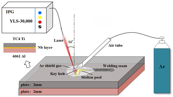
Figure 1.
Schematic of the welding test process.
Ti and Al alloys easily oxidize in the air, forming an oxide film. The welding area of the plates must be polished prior to welding to ensure the stability of the process. Industrial-grade anhydrous ethanol was used to clean the surface and remove impurities and pollutants. After cleaning, the plates were dried before welding. The experiment used a flat lap joint to investigate Ti/Al dissimilar alloy laser welding. The laser beam was angled 10° towards the welding speed direction and was focused on the surface of the plate. The defocusing amount was 0. A purity of 99.99% Ar gas was used as the welding protective gas to prevent high-temperature oxidation and the formation of pores when the welding pool came into contact with the air. The protective gas flow rate was set at 25 L/min. The high-speed camera was positioned perpendicular to the weld to record the dynamic behavior of the weld pool. The collected data was temporarily stored in the computer for subsequent analysis.
Based on preliminary experiments and literature research, the final decision was made to use the welding method with Ti above and Al below, with a laser power ranging from 1000 to 2000 W, a welding speed ranging from 10 to 20 mm/s, and an Nb sheet thickness ranging from 0 to 0.2 mm. The specific parameters are shown in Table 3.
Table 3.
Welding parameters used in this work.
This study initially conducted preliminary experiments to reduce spatter during the welding process and ensure good macroscopic formation of the weld without significant collapse. Subsequently, the laser power was gradually increased throughout the preliminary experiments to ensure that the welds under different Nb foil thicknesses had comparable effective weld penetration and width.
2.3. Test Analysis Methods
The metallographic and tensile specimens were prepared by electrical discharge machining perpendicular to the weld direction, as illustrated in Figure 2. The section morphology, distribution of the microcracks, and the elemental composition in the target area were analyzed using a HITACHI SU3900 scanning electron microscope (SEM), equipped with an energy dispersive X-ray spectrometer (EDS). The tests were performed with a Ti/Al lap joint configuration, and the specimens were clamped directly for shear testing. Significant errors occurred in the shear strength test results due to the load direction not being parallel to the Ti/Al interface. To ensure that the force line coincided with the interface, shims were placed at both ends of the tensile specimens. Using GB/T228.1-2010 as a reference, the shear tests were conducted on the specimens perpendicular to the weld direction using an INSTRON 8801 fatigue testing machine at a shear speed of 1 mm/min. Each welding test underwent three shear strength tests.
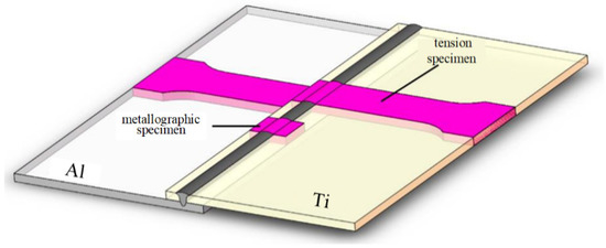
Figure 2.
Cutting positions of the metallographic and tensile specimens.
3. Results and Discussion
3.1. Effect of Nb on the Macroscopic Formation of Joints
The macroscopic formation of the weld was studied without the addition of Nb, to ensure the alloying process was carried out under good welding conditions. The results are shown in Figure 3 and Figure 4. Excessive welding energy input (150 J/mm) may result in the melting through of the Ti alloy and Al alloy, causing macroscopic cracks in the localized region of the weld. At a power of 1000 W and a welding speed of 10 mm/s, the welding energy input is 100 J/mm, and the Ti plate does not melt. However, at a power of 2000 W and a welding speed of 20 mm/s, despite the welding energy input being the same (100 J/mm), the weld basically penetrates the Ti/AL plate. This is mainly because the laser power is too small to create a sufficient keyhole depth to penetrate the titanium alloy. Even under the same heat input conditions, the welding penetration depth is inconsistent. Based on the macroscopic morphology of the weld, reducing the welding spatter and suppressing the deformation of the weld can be achieved when the welding power is 1750 W and the welding speed is 20 mm/s.
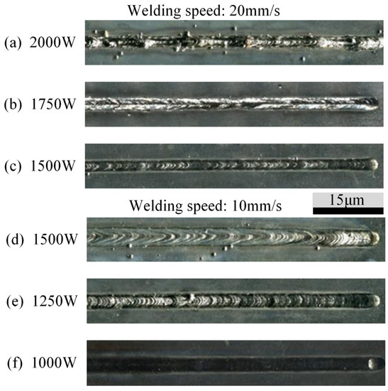
Figure 3.
The macroscopic formation of the weld surface in the absence of Nb, with varying welding parameters.
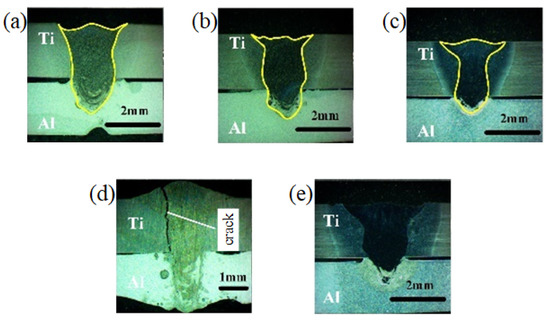
Figure 4.
The macroscopic formation of the weld cross-section in the absence of Nb, with varying welding parameters. (a): laser power 2000 W, welding speed 20 mm/s; (b): laser power 1750 W, welding speed 20 mm/s; (c): laser power 1500 W, welding speed 20 mm/s; (d): laser power 1500 W, welding speed 10 mm/s; (e): laser power 1250 W, welding speed 10 mm/s.
Subsequently, using the same process parameters (P = 1750 W, v = 20 mm/s), a 0.2 mm Nb sheet was welded, and the cross-sectional morphology before and after alloying is compared in Figure 5. With the presence of an intermediate Nb layer, the effective weld width and depth at the joint interface decreased, and there was no significant difference in macroscopic weld formation under the same welding process parameters. Thus, in this experiment, the laser power was gradually increased to ensure similar effective weld depth and width under varying Nb sheet thicknesses.
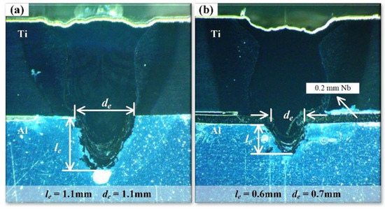
Figure 5.
Comparison of the cross-sectional morphology before and after alloying: (a) before alloying; (b) after alloying.
3.2. Effect of Nb on Microstructure of Joints
The microstructure of dissimilar metal laser-welded joints consisting of Ti and Al is highly intricate, with the brittle intermetallic compounds of Ti–Al being the deciding factor in the mechanical properties of the joints. Several intermetallic compounds of Ti–Al, such as Ti3Al, Ti2Al, TiAl, TiAl3, etc., can form within the joints during the welding process. The mechanical properties of the joint are greatly influenced by different Ti–Al intermetallic compounds.
Figure 6 presents the welded joint’s bottom profile before and after alloying. Upon comparison, the profile of the welded joint remains consistent before and after alloying. However, the high melting point of Nb results in less melting in the width direction after alloying, causing the melting width at the interface to narrow. Moreover, Nb may absorb a significant amount of energy during the welding process, affecting the fluctuation state of the keyhole. Consequently, there is a difference in the distribution of compounds at the bottom of the welded joint before and after alloying. The joint’s cross-section can be divided into four regions: the mixture zone (MZ), transition zone (TZ), thermal conductivity melting zone (TCMZ), and heat-affected zone (HAZ), as illustrated in Figure 6(b1,b2), after corrosion with Keller’s reagent. The mixture zone is the region of the Ti–Al intermetallic compounds formed by the mixing and cooling of Ti and Al alloys under the molten pool’s flow field during welding, containing significantly more Ti than Al. The transition zone is the element transition region gradually transitioning from a Ti-rich zone to an Al-rich zone, resulting in relatively more complex intermetallic compounds. The thermal conductivity melting zone is primarily caused by the lower melting point of Al compared to that of Ti–Al intermetallic compounds. After the Ti–Al intermetallic compounds solidify, heat is further transferred to the Al alloy, leading to a larger melting range of the Al alloy. Therefore, almost no Ti–Al intermetallic compounds are produced in this region. The heat-affected zone is the region where heat diffuses along the plate and causes a phase change in the Ti alloy during the welding process. Laser-melted Nb brought into the molten pool may regulate the welded joint’s microstructure, optimizing its mechanical properties.
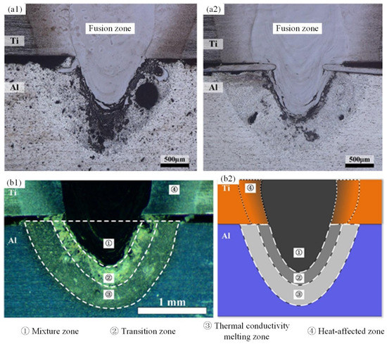
Figure 6.
(a) Bottom profile of the cross-section of the welded joint: (a1) before alloying, (a2) after alloying; (b) Division of the different microstructure morphologies: (b1) optical microscope image, (b2) sketch figure.
The TCMZ structure comprises three main types of Al-based structures: distinct columnar + equiaxed crystal zones, fully columnar crystal zones, and columnar + equiaxed crystal mixed zones, as depicted in Figure 7. These structures are primarily influenced by the welding temperature, melt flow, and chemical element diffusion. As the heat conducts to the Al alloy through the weld seam area during the welding process, the Al alloy absorbs the heat and its melting range continuously expands until the maximum boundary of the melting area is reached. During the cooling process, the temperature near the melting boundary drops, creating temperature conditions for columnar crystal growth. When the temperature falls below the liquidus temperature, the liquid metal near the melting boundary nucleates and grows on the Al matrix grains, indicating that the initial melting boundary is epitaxial growth. However, different grain growth mechanisms beyond the melting boundary lead to varying grain distribution in the TCMZ. Any disturbance in the TCMZ causes Ti to diffuse rapidly to the TCMZ near the TZ, resulting in the formation of granular Ti–Al metal compounds. These compounds, which act as nucleation points for equiaxed crystals, disperse near the weld zone and eventually grow together with columnar crystals, forming the distinct boundary columnar + equiaxed crystal zone shown in Figure 7a. In contrast, the fully columnar crystal zone in Figure 7b is the result of competition between the TCMZ grains. During the solidification process of the TCMZ, grains grow along the direction perpendicular to the contour due to the largest temperature gradient perpendicular to the weld seam contour direction, hindering and repelling the growth of unfavorably orientated grains. This results in a relatively stable welding pool without convection, and alloy elements do not diffuse to the TCMZ and TZ. At the bottom of the melting pool, kinetic energy and gravity generated by the fluctuation of small holes in the depth direction accelerate the diffusion and deposition of elements and Ti–Al compound particles to the bottom of the melting pool, causing grain fragmentation. These fragments and heterogeneous particles act as random nucleation points for equiaxed crystals. The area with nucleation points hinders the growth of columnar crystals, while the area without nucleation points forms columnar crystals, as shown in Figure 7c.
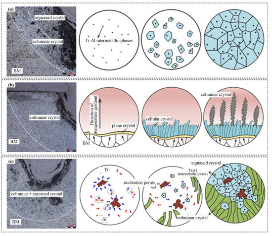
Figure 7.
Three different distribution states of the thermal conductivity melting zone structure: (a) distinct boundary columnar + equiaxed crystal zones, (b) fully columnar crystal zones, and (c) mixed equiaxed + columnar crystal zones.
The TZ is the intermediate area where the weld changes from the Ti-rich zone to the Al-rich zone. The internal structure of the TZ is complex and diverse. Due to the significant differences in melting points, thermal conductivity, and thermal expansion coefficients between titanium and aluminum, large welding stresses are generated in this area during the cooling process. These stresses can cause Ti–Al intermetallic compounds to form cracks in the TZ. Figure 8 shows the low-magnification SEM images of the joint before and after alloying, along with the distribution of the microcracks in the TZ. Microcracks were observed and depicted under high-magnification SEM. After alloying, a significant reduction in the number of microcracks in the TZ was observed. Before alloying, the microcracks were continuously distributed mainly on both sides of the weld zone. After alloying, the microcracks were locally and intermittently distributed mainly near the bottom and interface. The cracks can be characterized by the crack rate r, which is the ratio of the length of the microcracks to the total length of the transition zone, as shown in Figure 8. Here, l represents the total arc length of the transition zone, and li represents the arc length of the crack zone in the transition zone, as calculated by the Equation (1).
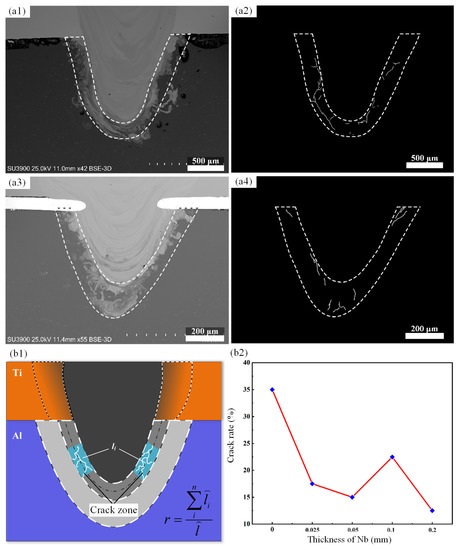
Figure 8.
(a1) SEM image and (a2) micro cracks in the joint transition zone before alloying; (a3) SEM image, (a4) micro cracks in the joint transition zone after alloying; (b1) calculation method for crack rate; (b2) crack rate in transition zone under different alloying contents.
Two sections with different Nb content were randomly selected for crack analysis, and the crack rate was obtained for each Nb content, as shown in Figure 8(b1,b2). It can be observed that the overall microcrack rate in the transition zone was significantly reduced after alloying, and the crack rate gradually decreased with the increase of Nb content, indicating the significant effect of Nb in inhibiting cracks in the transition zone. Scholars have conducted molecular dynamics simulations to explore the effect of Nb on crack propagation in the TiAl alloy, and it was found that Nb can reduce the relaxation energy and increase the binding energy between TiAl alloy atoms, thereby enhancing their stability. With increasing Nb content, the cohesion between atoms increases and the peak stress value rises. Consequently, when the stress reaches its peak value, the crack begins to propagate slowly, and the stress decreases gradually. This indicates that Nb enhances the ductility of the TiAl alloy [20].
During the welding process, there are significant changes in the recoil pressure in the depth direction and the violent fluctuation of small holes occurs. Consequently, a small amount of Ti-based melt splashes into the Al-based melt at the bottom of the weld, forming island-shaped Ti–Al intermetallic compounds, as illustrated in Figure 9(a1,a2). The Ti-based melt splashed from the weld area generates a certain vortex, which results in the sandwiching of Al-based melt between Ti-based melt. This process leads to the formation of complex and diverse Ti–Al intermetallic compounds within the islands. EDS composition analysis of three typical representative areas, by SEM, indicates that the island-shaped Ti–Al compound area has at least three phase compositions. The analysis of Point 1 shows that the Ti–Al intermetallic compound in this area may contain Al2Ti with the Nb element. Point 2 corresponds to an area that may contain Al3Ti with the Nb element, while Point 3 corresponds to an area that may contain Ti2Al with the Nb element. At low magnification, cracks were observed at the bottom of the weld. High magnification observation of the tissue structure and the crack morphology showed differences, as depicted in Figure 9(a3,a4). The point scan and line scan results suggest that Point 4 corresponds to a coral-like area that may contain Al3Ti with the Nb element. Point 5 corresponds to a groove-like area that is mainly composed of Al-based tissue, indicating that this structure is not a crack. Point 6 corresponds to a white area that may contain TiAl with the Nb element.
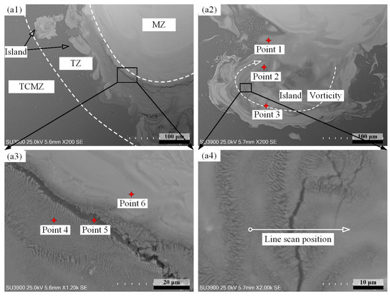
Figure 9.
The formation process for the microstructure morphology in the transition zone: (a1): zone I; (a2): zone II; (a3): partial enlarged view of (a1); (a4): partial enlarged view of (a2).
3.3. Effect of Nb on the Mechanical Properties of Joints
Three shear strength tests were conducted on the joints, with varying Nb content, to investigate the impact of Nb content on the joints’ mechanical properties. The experimental results are illustrated in Figure 10a. As depicted in the figure, the average strength of the Ti/Al joint increases after alloying, and the joint strength reaches its peak (approximately 192 N/mm) when the Nb foil thickness is 0.05 mm. The joint strength is boosted by approximately 25% compared to pre-alloying, indicating that adding Nb as an alloying element to the joint can significantly enhance its strength. Figure 10b illustrates the shear-force displacement curves under two Nb contents, and no obvious yielding process is observed. The shear force drops sharply after reaching the maximum value, indicating typical brittle fracture characteristics.
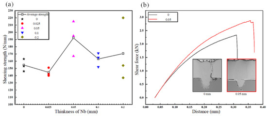
Figure 10.
(a) Strength of the joints with different Nb contents; (b) Shear strength test process before and after alloying.
For fracture forms in dissimilar welded joints, Fu et al. [21] studied the hydrogen induced stress corrosion cracking behavior of SUS301L-MT laser-arc hybrid welding joints and found that the cracks mainly formed intergranular cracking, transgranular cleavage, and secondary cracks on the fracture surface. Zhan et al. [22] studied the ultrasonic welding between AZ31B magnesium alloy and pure copper. It was found that the main component of the interface diffusion layer was Mg2Cu, and the fracture mode of the joint was an interface type fracture, with a maximum joint strength of 2798 N. Tayyebi et al. [23] prepared Al/Cu/Mg multilayer composite materials using the accumulative roll welding process and annealed them at different temperatures and times. It was found that the accumulative strain under different annealing conditions had very little effect on the thickness of the intermetallic compounds. In addition, it was determined that the growth mechanism of the Al/Mg intermetallic layer was controlled by diffusion and reaction. In this work, three types of fracture forms were observed during the shear testing process, namely root fracture, lateral fracture, and interface fracture. These fracture forms correspond to distinct fracture processes and morphologies, indicating differences in fracture mechanisms.
Figure 11a depicts the schematic diagram of the side fracture of the joint along the weld zone, and Figure 11b presents the actual transverse fracture morphology. As illustrated in the figure, the joint crack originates from the intersection of the interface and the weld zone, extends through the entire weld zone, and eventually causes the joint’s failure. Additionally, the transition zone, which is subjected to tensile stress, is highly susceptible to cracks, and cracks can initiate from the interface and propagate towards the bottom of the weld. Figure 11c provides a local magnification of the fracture position of the weld, revealing multiple microcracks near the main crack propagation path, dispersed in the weld zone near the melting boundary. A line scan of the melting boundary indicates that the chemical composition content near the melting boundary exhibits significant fluctuations, as depicted in Figure 12. In the weld zone, each chemical element’s content remains stable, while the relative strength of the Ti, N, and V elements significantly decrease in the area between the two microcracks, and the relative strength of the Al element increases significantly, indicating an enrichment of the Al element between the two microcracks. Moving from the MZ to the HAZ, the relative strength of the Ti, N, and V elements significantly increase, surpassing that in the MZ, while the relative strength of the Al element drops sharply and remains steady. EDS composition analysis was carried out on both sides of the fracture position, and Table 4 shows the results. Points 1 and 2 display comparable chemical compositions and may be Ti3Al. Figure 11d provides the local morphology of a crack induced by tensile stress in the weld zone. The Ti–Al intermetallic compound in the TZ is flocculent, primarily due to the solidification of the Ti–Al intermetallic compound in the MZ during the welding process, while the thermal conductivity melting zone stays liquid. Upon cooling, the Ti element diffuses irregularly and forms a flocculent Ti–Al compound. Figure 12 displays the results of line scanning analysis conducted on the TZ. The figure depicts the changing trend in each element’s relative strength in the TZ, demonstrating that the gradient of the element content change in the TZ is relatively high, resulting in the formation of a complex compound. Figure 11e,f shows the extension morphology and element distribution map for the transition zone crack, respectively. By comparison, it is evident that the microstructure’s brightness corresponds to the Ti content, and the crack generally propagates along the Ti-rich zone.
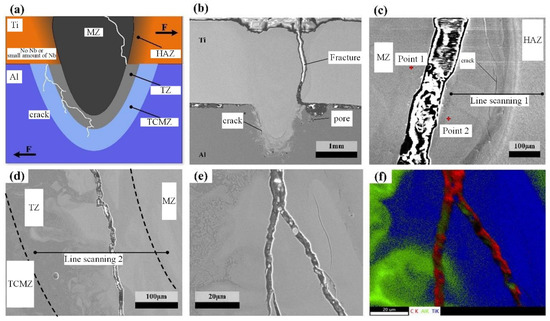
Figure 11.
Side fracture morphology of the joint: (a) sketch figure; (b) actual cross-sectional fracture morphology; (c) partial enlarged view of weld fracture location; (d) local morphology of cracks induced by tensile stress in welds; (e) crack propagation morphology in the transition zone; (f) element distribution map in the transition zone.
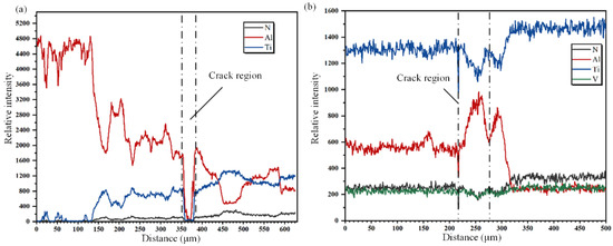
Table 4.
EDS point analysis results in Figure 11.
Secondary cracks can be observed on the cross-section of the weld seam before alloying, as illustrated in Figure 13a, using high-magnification SEM. The propagation path of the secondary cracks is flat, indicating brittle fracture characteristics. Figure 13 displays many irregularly shaped Ti–Al intermetallic compounds distributed on the large cleavage plane with a darker contrast. The atomic fraction for Ti and Al at Point 1 is 53.9% and 15.8%, respectively, indicating that the phase composition is Ti3Al. Another typical fracture morphology, shown in Figure 13c, is characterized by a small, stepped shape. The parallel cleavage planes indicate uniform stress and phase distribution in this region during the fracture process. Component testing in the two regions with bright and dark contrast reveals the atomic content of Ti and Al at Point 2 to be 83.9% and 2.1%, respectively, while at Point 3, the atomic content of Ti and Al are 63.5% and 5.4%, respectively. These results indicate that the region is a Ti-based alloy structure.
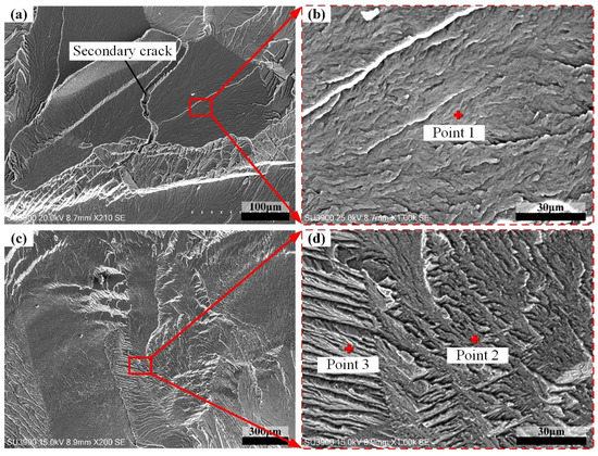
Figure 13.
Local features of the Ti-side fracture in the joint before alloying: (a): zone I; (b): partial enlarged view of (a); (c): zone II; (d): partial enlarged view of (c).
Figure 14a presents a schematic diagram illustrating the interface fracture process of the joint, while Figure 14b displays the actual cross-sectional fracture morphology when the joint was alloyed with a 0.05 mm Nb foil. The regions labeled 1, 2, 3, and 4 in Figure 14b correspond to Figure 14c–f, respectively. The figure reveals that under tensile stress, the weld seam undergoes macroscopic fracture, whereas it remains effectively connected under compressive stress during the interface fracture process. The microcracks are more sensitive to tensile stress, hence the crack initiation and propagation speed is faster on the tension side. Microcracks also propagate on the compression stress side and at the bottom of the weld seam, as shown in Figure 14e,f, but these cracks have not yet connected and converged during the expansion process. As the shear force increases, the Nb foil tip embedded in the weld seam interior causes a cutting action, leading to stress concentration at the tip under shear force and crack initiation.
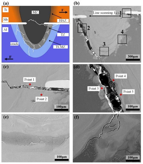
Figure 14.
The fracture morphology of the joint interface cross-section (0.05 mm Nb foil): (a) sketch figure; (b) actual cross-sectional fracture morphology; (c) partial enlarged view of zone 1 in (b); (d) partial enlarged view of zone 2 in (b); (e) partial enlarged view of zone 3 in (b); (f) partial enlarged view of zone 4 in (b).
EDS point analysis was performed on Regions 1 and 2 to investigate the composition of the tissues near the crack propagation path. The scan results are presented in Table 5. In the weld region, the gray area is mainly composed of the TiAl compound, whereas the bright area is mainly composed of the Ti3Al compound. In the transition region, TiAl3, TiAl2, TiAl, and their mixtures are formed from the outside to the inside, in accordance with the compositional change law from the Al-rich to the Ti-rich region. The crack propagates primarily along the TiAl2 compound, on the side subjected to tensile stress. This may be due to the higher susceptibility of TiAl2 to microcracks under welding stress, as well as its expansion and connection under shear stress, thereby guiding and accelerating the propagation of the main crack.
Table 5.
EDS point analysis results in Figure 14.
Figure 15a shows the typical fracture morphology of the Ti-side interface, where three distinct regions are observed. Figure 15b displays an enlarged view of Region 1, where numerous small dimples indicate a ductile fracture in that specific region. Point 1 scan analysis reveals an enrichment of Ti atoms (85.3%), along with Al (6.2%), and Nb (1.5%) atoms, enhancing the toughness of the area. Figure 15c provides a closer look at Region 2, which exhibits a fracture composed of layered Ti–Al intermetallic compounds in a fish-scale shape formed by small, stepped surfaces. Point 2 analysis shows Ti atoms accounting for 63.5%, Al atoms accounting for 19.4%, indicating the possibility of Ti3Al. Figure 15d depicts a shear force joint fracture along the interface in Region 3, where winding slip lines form on the fracture surface. Point 3 analysis shows Ti atoms accounting for 64.9%, Al atoms accounting for 30.7%, and Nb atoms accounting for 1.7%, indicating the possibility of Ti2Al. Therefore, niobium microalloying leads to the joint mainly fracturing in the transition zone and interface, exhibiting brittle and ductile fracture characteristics with obvious cleavage planes, many dimples, and slip lines.
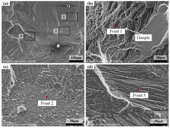
Figure 15.
Typical fracture morphology of the interface fracture: (a) typical fracture morphology on the Ti side of interface fracture; (b) partial enlarged view of zone 1 in (a); (c) partial enlarged view of zone 2 in (a); (d) partial enlarged view of zone 3 in (a).
Figure 16a presents a schematic diagram of the root fracture that occurred in the joint, while Figure 16b shows the actual section fracture morphology under 0.2 mm Nb alloying, with Regions 1, 2, and 3 corresponding to Figure 16c–e, respectively. Due to the shallow welding depth, the microcracks generated as a result of the stress concentration caused by the difference in hardness between the inside and outside of the transition zone and the cooling process are relatively few. Once the joint is subjected to shear force, the stress concentration near the interface of the aluminum alloy thermal conductivity melting zone and the transition zone on the tensile side cause cracks to occur, first at the interface of the two regions on the surface of the aluminum alloy plate, as depicted in Figure 16. The Al alloy structure of the thermal conductivity MZ has good toughness and plasticity, leading to low crack sensitivity, while the weld zone structure is dense and hard, with no microcrack generation. Consequently, the crack requires higher energy to propagate along this area, limiting propagation to the TZ, where the propagation resistance is minimal. Secondary cracks in the peripheral Ti–Al intermetallic compounds arise along the propagation path of the primary crack, as shown in Figure 16c. When the crack emerges from the interface and extends to the bottom of the weld, the tissue near the surface of the Al undergoes greater deformation than the tissue near the lower part, leading to the extension of the crack from the root of the weld to the position with more significant deformation to balance the stress caused by the difference in the deformation of the weld in the depth direction, as demonstrated in Figure 16d. As the shear force continues to increase, the corresponding TZ subjected to compressive stress produces a growing shear force parallel to the contour, and the crack extends and connects along the contour. Due to the complex structure of the transition zone, the crack propagation process leads to the occurrence of secondary cracks, as depicted in Figure 16e.
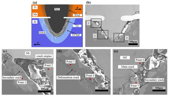
Figure 16.
The morphology of the root fracture (0.2 mm Nb foil): (a) sketch figure; (b) actual cross-sectional fracture morphology; (c) partial enlarged view of zone 1 in (b); (d) partial enlarged view of zone 2 in (b); (e) partial enlarged view of zone 3 in (b).
Point analysis was conducted to investigate the tissue composition along the crack propagation path. The scanning points were labeled in the figure, and the scanning results are shown in Table 6. Based on the analysis results, the grey area marked by Points 3 and 4 mainly consists of Al, indicating that the deformation crack propagates along the melting zone of the aluminum alloy. Compounds corresponding to Points 1 and 2 are possibly TiAl2 and TiAl, respectively. These indicate that the phase composition of the transition zone is complex, and the phase composition trend is consistent with the law of elemental diffusion. Compounds corresponding to EDS Points 5 and 6 are possibly TiAl and Ti3Al, respectively. This indicates that the proportion of the Ti element in the phase composition is higher closer to the inside of the weld.
Table 6.
EDS point analysis results in Figure 17.
Figure 17a presents a magnified view of the Ti-side fracture surface, revealing clear edges and a mountain-shaped appearance with river-like cleavage steps. The edges of the steps contain white bright spots of varying sizes and shapes, indicating a brittle fracture failure mode in this area. Point analysis identified that the grey area corresponding to Point 2 has a Ti atomic content ratio of 39.6% and an Al atomic content ratio of 48.4%, suggesting the possibility of TiAl phase composition. In contrast, the bright area corresponding to Point 1 has a Ti atomic content ratio of 84.2% and an Al atomic content ratio of 10.1%, indicating the possibility of Ti alloy fragments. This finding suggests that the distribution of intermetallic compound organization is uneven, and the cleavage crack is partially hindered after extending to the Ti alloy organization, causing the crack front to pull and the direction to change, forming a new cleavage surface. Figure 17b displays a typical cleavage fracture with a regular river pattern, revealing clear secondary cracks with straight paths and brittle fracture characteristics. The dark area corresponding to Point 3 has a Ti atomic content ratio of 39.6% and an Al atomic content ratio of 39.4%, indicating a possible TiAl phase composition and an extension of the cleavage surface along the TiAl phase. Figure 17c shows a large number of laminated and block-like intermetallic compound accumulations with significant height differences, mainly related to the phase composition and stress state of the transition zone. The more complex the phase composition and stress state, the more intricate the corresponding fracture morphology. Figure 17d indicates, through Point 5 component analysis, that the vast majority of the atomic ratio is Al, which confirms that the organization in this area is an Al alloy and that the crack did not extend completely along the TZ.
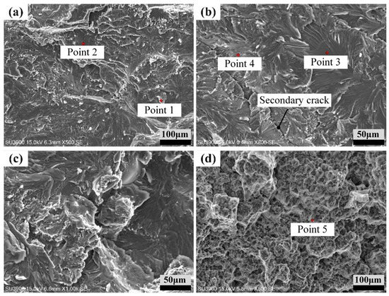
Figure 17.
The features of the root fracture surface: (a) partial enlarged view of Ti side fracture; (b) typical cleavage fracture with a regular river pattern; (c) a fracture formed by the combination and accumulation of a large number of layered and blocky metals; (d) typical dimple fracture characteristics.
4. Conclusions
The purpose of this study is to mitigate the formation of brittle phases during the laser welding of dissimilar Ti/Al metals, thereby enhancing the mechanical properties of the joints. In this investigation, an innovative approach is adopted, utilizing Nb foil as an interlayer to effectively minimize the formation of brittle intermetallic phases during dissimilar welding. The main findings from this study are:
- When an intermediate Nb foil is present between the Ti alloy and Al alloy under the same welding process parameter, the effective welding width and joint penetration depth at the weld interface are reduced compared to unalloyed weld seams.
- After Nb alloying, the cracking rate in the joint transition zone is significantly reduced. This is mainly attributed to the ability of Nb to lower the relaxation energy, increase the binding energy between Ti–Al alloy atoms, and enhance stability.
- When a 0.05 mm Nb foil is used as the intermediate alloy layer, the average shear strength of the joint is the highest, reaching 192 N/mm, which is a 25% increase compared to unalloyed weld seams.
- The unalloyed Ti/Al weld joint mainly fractured along the melting zone, displaying clear cleavage fracture characteristics and a complete brittle fracture with numerous cleavage steps on the fracture surface. After adding Nb foil, the joint fracture behavior was mainly observed at the transition zone and weld interface, displaying obvious cleavage surfaces, and exhibiting numerous tough dimples and slip stripes that are indicative of both cleavage and ductile fracture characteristics, which suggests a brittle–ductile fracture.
Author Contributions
Conceptualization, H.P.; methodology, H.P.; software, H.P.; validation, H.P., Y.W., S.G., A.Y., C.H. and J.Z.; formal analysis, H.P.; investigation, H.P., Y.W., S.G., A.Y., C.H. and J.Z.; resources, H.P.; data curation, H.P.; writing—original draft preparation, H.P.; writing—review and editing, H.P., Y.W., S.G. and C.H.; visualization, H.P. and Y.W.; supervision, H.P.; project administration, S.G.; funding acquisition, S.G. All authors have read and agreed to the published version of the manuscript.
Funding
The Project was Supported by the National Key Research and Development Program of China No. 2022YFB3404802, and GuangDong Basic and Applied Basic Research Foundation No. 2023A1515010081.
Data Availability Statement
Data sharing is not applicable.
Conflicts of Interest
The authors declare no conflict of interest.
References
- Sanders, D.; Edwards, P.; Grant, G.; Ramulu, M.; Reynolds, A. Superplastically Formed Friction Stir Welded Tailored Aluminum and Titanium Blanks for Aerospace Applications. J. Mater. Eng. Perform. 2010, 19, 515–520. [Google Scholar] [CrossRef]
- Chen, Y.; Sun, S.; Zhang, T.; Zhou, X.; Li, S. Effects of post-weld heat treatment on the microstructure and mechanical properties of laser-welded NiTi/304SS joint with Ni filler. Mater. Sci. Eng. A 2020, 771, 138545. [Google Scholar] [CrossRef]
- Zhang, Z.; Chen, J.; Wang, J.; Han, Y.; Yu, Z.; Wang, Q.; Zhang, P.; Yang, S. Effects of solder thickness on interface behavior and nanoindentation characteristics in Cu/Sn/Cu microbumps. Weld. World 2022, 66, 973–983. [Google Scholar] [CrossRef]
- Zhu, Z.Y.; Liu, Y.L.; Gou, G.Q.; Gao, W.; Chen, J. Effect of heat input on interfacial characterization of the butter joint of hot-rolling CP-Ti/Q235 bimetallic sheets by Laser + CMT. Sci. Rep. 2021, 11, 10020. [Google Scholar] [CrossRef] [PubMed]
- Lv, S.; Cui, Q.; Huang, Y.; Jing, X. Influence of Zr addition on TIG welding–brazing of Ti–6Al–4V toAl5A06. Mater. Sci. Eng. A 2013, 568, 150. [Google Scholar] [CrossRef]
- Shouzheng, W.; Yajiang, L.; Juan, W.; Kun, L.; Pengfei, Z. Microstructure and joining mechanism of Ti/Al dissimilar joint by pulsed gas metal arc welding. Int. J. Adv. Manuf. Technol. 2014, 70, 1137–1142. [Google Scholar] [CrossRef]
- Liu, K.; Li, Y.; Wei, S.; Wang, J. Interfacial Microstructural Characterization of Ti/Al Joints by Gas Tungsten Arc Welding. Mater. Manuf. Process. 2014, 29, 969–974. [Google Scholar] [CrossRef]
- Sohn, W.H.; Bong, H.H.; Hong, S.H. Microstructure and bonding mechanism of Al/Ti bonded joint using Al–10Si–1Mg filler metal. Mater. Sci. Eng. A 2003, 355, 231. [Google Scholar] [CrossRef]
- Shehab, A.A.; Sadrnezhaad, S.; Torkamany, M.; Hasanabadi, M.F.; Alali, M.; Mahmoud, A.; Abass, M.H.; Kokabi, A. Ring-like laser spot welding of Ti grade2 to AAl3105-O using AlSiMg filler metal. Optik 2020, 206, 163630. [Google Scholar] [CrossRef]
- Chen, W. Microstructure and mechanical properties of tungsten inert gas welded–brazed Al/Ti joints. Sci. Technol. Weld. Join. 2016, 21, 547–554. [Google Scholar] [CrossRef]
- Zhang, C.; Robson, J.D.; Haigh, S.J.; Prangnell, P.B. Interfacial Segregation of Alloying Elements During Dissimilar Ultrasonic Welding of AA6111 Aluminum and Ti6Al4V Titanium. Met. Mater. Trans. A 2019, 50, 5143–5152. [Google Scholar] [CrossRef]
- Zhang, J.; Zhao, J.; Hu, K.; Gao, Q.; Zhan, X. Improving intermetallic compounds inhomogeneity of Ti/Al butt joints by dual la-ser-beam bilateral synchronous welding-brazing. Opt. Laser Technol. 2022, 146, 107533. [Google Scholar] [CrossRef]
- Li, Y.; Shi, L.; Wu, C.; Li, S.; Jiang, Y. Elucidation of welding speed on the microstructure and mechanical properties of medium-thick dissimilar Al/Ti double-side friction stir welded joint. Mater. Charact. 2023, 200, 112910. [Google Scholar] [CrossRef]
- Zhao, J.; Jiang, P.; Geng, S.; Wang, Y.; Xu, B. Effect of pulsed laser pretreatment induced pit-structure on the formation of intermetallic compounds in titanium-aluminum dissimilar welded joints. Opt. Laser Technol. 2023, 167, 109589. [Google Scholar] [CrossRef]
- Fang, J.; Wang, J.; Wang, Y.; He, H.; Zhang, D.; Cao, Y. Microstructure evolution and deformation behavior during stretching of a compositionally inhomogeneous TWIP-TRIP cantor-like alloy by laser powder deposition. Mater. Sci. Eng. A 2022, 847, 143319. [Google Scholar] [CrossRef]
- Zhou, X.; Chen, Y.; Li, S.; Huang, Y.; Hao, K.; Peng, P. Friction Stir Spot Welding-Brazing of Al and Hot-Dip Aluminized Ti Alloy with Zn Interlayer. Metals 2018, 8, 922. [Google Scholar] [CrossRef]
- Li, X.; Li, C.; Cao, Z.; Yang, P. The effect of Zn interlayer on microstructure and mechanical performance during TIG overlap welding-brazing of Al to Ti. Mater. Res. Express 2020, 7, 026514. [Google Scholar] [CrossRef]
- Jin, H.; Jia, Q.; Xian, Q.; Liu, R.; Cui, Y.; Xu, D.; Yang, R. Seeded growth of Ti–46Al–8Nb polysynthetically twinned crystals with an ultra-high elongation. J. Mater. Sci. Technol. 2020, 54, 190–195. [Google Scholar] [CrossRef]
- Zhang, W.J.; Deevi, S.C.; Chen, G.L. On the origin of superior high strength of Ti–45Al–10Nb alloys. Intermetallics 2002, 10, 403. [Google Scholar] [CrossRef]
- Li, Y.; Rui, Z.; Luo, D.; Yan, C. Effect of Niobium on Crack Propagation in Single Crystal γ-TiAl Alloy Using Molecular Dynamics Simulation. J. Mater. Sci. Eng. 2017, 35, 502–507. [Google Scholar]
- Fu, Z.; Yang, B.; Shan, M.; Li, T.; Zhu, Z.; Ma, C.; Zhang, X.; Gou, G.; Wang, Z.; Gao, W. Hydrogen embrittlement behavior of SUS301L-MT stainless steel laser-arc hybrid welded joint localized zones. Corros. Sci. 2020, 164, 108337. [Google Scholar] [CrossRef]
- Zhao, D.; Jiang, C.; Zhao, K. Ultrasonic welding of AZ31B magnesium alloy and pure copper: Microstructure, mechanical properties and finite element analysis. J. Mater. Res. Technol. 2023, 23, 1273–1284. [Google Scholar] [CrossRef]
- Tayyebi, M.; Adhami, M.; Karimi, A.; Rahmatabadi, D.; Alizadeh, M.; Hashemi, R. Effects of strain accumulation and annealing on interfacial microstructure and grain structure (Mg and Al3Mg2 layers) of Al/Cu/Mg multilayered composite fabricated by ARB process. J. Mater. Res. Technol. 2021, 14, 392–406. [Google Scholar] [CrossRef]


Disclaimer/Publisher’s Note: The statements, opinions and data contained in all publications are solely those of the individual author(s) and contributor(s) and not of MDPI and/or the editor(s). MDPI and/or the editor(s) disclaim responsibility for any injury to people or property resulting from any ideas, methods, instructions or products referred to in the content. |
© 2023 by the authors. Licensee MDPI, Basel, Switzerland. This article is an open access article distributed under the terms and conditions of the Creative Commons Attribution (CC BY) license (https://creativecommons.org/licenses/by/4.0/).