Abstract
High-stiffener-web combined opening girders used on passenger ships are prone to plastic hinge failures around the opening area and overall instability under combined and vertical loads, exhibiting complex buckling behaviors. In response to such situations, a series of numerical simulations and experiments on combined opening girders were conducted, considering several affecting factors such as opening shapes, initial crack defects, strengthening measures and stiffener web dimensions. On the basis of the verification of the reliability of the numerical method, the load-bearing characteristics of the combined open plate girders were investigated. It is concluded that the lumbar round opening can lead to localized plastic hinge failure phenomena, complicating the buckling behavior. In contrast, the inclusion of stiffeners can significantly improve the load-bearing capacity after the point at which instability occurs in the original specimen. In addition, detailed relationships between deformation trends and external loads are illustrated, which can be used as a reference for the optimal design of combined opening plate girders in actual ship structures.
1. Introduction
The hull structure of modern ships is usually made up of a plate frame structure. As for passenger ships, a large number of long-span high-web combined opening girders have been introduced in the accommodation area to meet the needs of individual room arrangements [1,2] and the laying of cables and pipelines [3,4]. Compared to common girder structures on ships, these structures have a higher stiffener web height, a greater number of openings and more complex opening shapes, resulting in a more complex buckling form of the structure under a combination of axial compression loads caused by overall longitudinal bending and local loads on the deck [5,6,7]. Therefore, it is necessary to investigate the load-bearing capacity and buckling behavior of the structure under combined loads, taking into account some factors such as dimensional parameters, initial crack defects and strengthening measures.
The opening girder structure is usually made up of an opening web and upper and lower wing plates. Thus, the original investigations can be traced back to the opening plate structure. Brown et al. [8,9,10] investigated the relationship between the load-bearing capacity of opening steel loads and the bending and shear loads, considering the size and location of the openings. This was basically the beginning of the investigation of the load-bearing capacity of opening structures [11]. Shanmugam et al. [12,13] investigated the effect of opening shapes, opening sizes and the length–width ratio of the opening plate with the aid of the finite element method. Sawy et al. [14] investigated the effect of the opening bias at the center of the plate on the elastic buckling behavior of the plate based on the Timoshenko theory. Paik [15,16,17] used a non-linear finite element method to investigate the relationship between the ultimate strength of opening plates and the proportion of bending and shear loads, and to propose a critical stress equation. In terms of experimental methods, Saad-Eldeen, from the University of Lisbon, conducted a systematic study. Saad-Eldden first investigated the failure behavior of opening plates under combined lateral and axial loads, considering the shape and size of the openings [18]. In further investigations, he considered the effects of initial crack defects, material corrosion and reinforcement on the structural load-bearing capacity of opening plates and found that reducing the area of a single opening and increasing the number of openings could improve the load-bearing capacity when the openings were of the same size. Controlling the initial defects of the structure increased the load capacity of the structure more significantly, and the reinforcement made the deformation of the structure more linear [19,20,21,22,23].
Based on the investigation of opening plates, the research has been extended to opening girders. Cristopher et al. [24] used the T-section method and the hole-section method to model the mechanics of opening girders, but there were problems concerning the poor computational accuracy for dense opening structures. Chung et al. [25,26] proposed a method using action curves to predict the load-bearing capacity of opening girders of different shapes and sizes under bending and shear loads, simplifying the difficulty of application in engineering scenarios. The team of Renjun Yan, from the Wuhan University of Technology in China, designed relevant ballast experiments to investigate the load-bearing capacity of specimens for conventional ship opening girders and compared them with the results of numerical calculations, finding that the buckling behavior and the ultimate load-bearing values of the specimens obtained from the numerical simulation fit well with the experimental results. In addition, the comparison revealed a significant influence of the initial axial force in accelerating the buckling of the structure when it reached the yielding stage. For the elastic phase, the effect is not obvious [27,28,29].
As can be seen from the above literature, the conventional analytical method is not sufficiently adaptable to complex combined open beam-bearing-capacity calculation problems, and it is complex to solve and difficult to apply. But with the development of computer hardware and software technology, finite element numerical simulation methods have become a common method for fast and convenient predictions of complex engineering problems. And the experimental method can help in validating the results of numerical simulations and aid in the correction of individual parameters of numerical simulations.
In this study, the ultimate strength and buckling behavior of typical combined opening girders were investigated using numerical simulations combined with experimental verification. Firstly, tensile experiments were carried out to determine the parameters of the material for the subsequent calculation. Next, considering factors such as opening shapes, initial crack defects, strengthening measures and stiffener web dimensions, the relationship between the load-bearing capacity, buckling behavior and surface strain of the specimen was investigated using numerical calculation methods combined with experiments. Finally, on the basis of confirming the reliability of the numerical calculation method, the load-bearing capacity and buckling behavior of the combined opening plate frame structure were investigated using numerical methods, and optimization measures are proposed.
2. Experimental Design
2.1. Specimen
The specimens investigated were selected from a longitudinal deck girder with openings from a passenger ship. Unlike conventional ships, passenger ships have many interferences in the hull structure due to the dense arrangement of pipelines and cables, which require a large number of combined openings in the web and result in a large loss of structural strength. The actual structure is shown in Figure 1.

Figure 1.
Diagram of the actual view of combined opening girders (a) without ribs and (b) with ribs.
The combined opening girder between two bulkheads was selected for investigation, consisting of three parts, i.e., plate, stiffener web and stiffener flange. The common opening form specimens on passenger ships were selected for investigation, identified as specimens A and B. In addition, some girders were reinforced by ribs (as shown in Figure 1b). Specimen D was identified based on this form, and the ribs were simplified to the shape of stiffeners. Furthermore, to investigate the relationship between initial crack defects and the buckling behavior of the structure, specimen C was identified. Finally, to compare the difference between the high-web structure of passenger ships and the low-web structure of conventional ships, specimen E was identified.
In conclusion, to investigate the load-bearing capacity and buckling behavior of the specimens under combined loads, factors such as opening shapes, initial crack defects, reinforcement measures and stiffener web dimensions were taken into account, and comparison specimens were designed for a systematic experimental investigation. The dimensions of the specimens are shown in Figure 2.
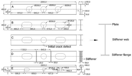
Figure 2.
Diagram of the specimen dimensions (mm).
As shown in Figure 2, 450 mm web height girders with round and lumbar round openings were selected as the objects of investigation (specimens A and B). For specimen C, the web height and opening sizes were the same as those of specimen B. However, a 2 mm width crack was cut in the middle of the stiffener flange to investigate the effect of the initial crack on the load-bearing capacity and buckling behavior of the specimens. For specimen D, the web height and opening sizes were also the same as those of specimen B. But in the middle of the round opening and lumbar round openings, there were ribs to support the plate and the stiffener flange. Finally, for specimen E, the web height was reduced to 225 mm, half that of the specimens above. Correspondingly, the size of the openings was scaled down in the same proportion. The detailed opening dimensions are shown in Figure 2. The specimens used for the experiment were welded using carbon dioxide gas shield welding. The manufacturing process was carried out in segments. After welding, the maximum horizontal deformation was measured to be 5.3 mm, and the maximum vertical deformation was 2 mm, which enabled effective control of the deformation during the manufacturing process.
2.2. Experimental Design
2.2.1. Equipment Arrangement
A loading system was designed to have an axial compression load and a uniform load across the span. In the axial direction, a hydraulic jack with 500 kN thrust was used for loading. And in the vertical direction, a 4000 kN thrust servo actuator was used. To simulate the vertical uniform load applied around the span (±355 mm), three spacers were placed to simulate the uniform load. Above this, a distribution girder was arranged to apply the vertical load. At the ends of the girders, rollers and pulleys were set to release the rotational freedom of the ends. In addition, the height of the rollers and pulleys was adjusted with wooden blocks, and the center was aligned with the neutral axis of the girder. In order to keep the axial forces stable, pretensioned ropes were placed on both sides of the girder to limit the slight deformation of the reaction frame. The layout of the experimental setup is shown in Figure 3.
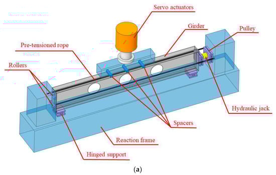
Figure 3.
Diagram of the experimental scenario: (a) principal models; (b) physical models.
In order to evaluate the deformation of the specimen, electronic displacement gauges were arranged at several measuring points on the girders. In addition, stresses at typical locations such as around openings were monitored by posting strain gauges and strain flowers on the surface of the girders. The displacement gauge was of type YWD, with a range of 100 mm and a measuring accuracy of ±0.01 mm. Seven displacement gauges (D1 to D7) were arranged for each specimen to measure the displacement values at the corresponding measurement points. Two displacement gauges were arranged in the plate to measure the vertical displacement at the ends of the plate. And for the stiffener flange, five displacement gauges were arranged, and the positions of the displacement gauges for the five specimens were aligned for comparison with each other. For specimen C only, displacement gauge D5 was eliminated due to the presence of the initial crack, which made it impossible to arrange displacement gauges at the mid-span position. In addition, for the arrangement of the strain gauges and rosettes, at areas where the stresses around the openings were more complex, strain flowers were set up to collect the strain values. For areas with a relatively simple stress distribution, strain gauges were set up for measurement. For the following analysis, the values of the displacement (D5) and stress (F-G-3) in the middle of the stiffener flange were selected. The complete arrangement of the displacement gauges, strain gauges and strain rosettes is shown in Figure A1 and Figure A2 in Appendix A.
2.2.2. Material Properties
To determine the material properties of the steel used for the specimens, tensile experiments were carried out. The geometry of the tensile experiment specimens was determined according to the Chinese National Standard (GB/T 228.1-2021) [30]. The five AH36 specimens were machined from the base material via line cutting. The dimensions of the specimens are shown in Figure 4. The experiment was carried out using a 500 kN universal testing machine, and the stretching rate was 0.2 mm/min [31]. Strain gauges were attached to both sides of the tensile zone of the specimens to monitor the strains.
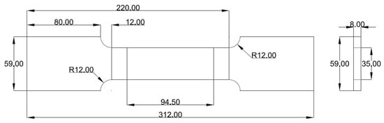
Figure 4.
Diagram of tensile specimen dimensions (mm).
During the experiment, in the elastic phase, the deformation of the specimens was small as the load increased. When entering the yield phase, the load oscillated around 375 MPa, and the deformation of the specimens was similarly insignificant. Subsequently, the external load increased again by a certain amount, and the deformation of the specimens increased significantly. When the ultimate load was reached, the specimens suddenly cracked with a loud clang. The fractures largely occurred in the middle of the marking area and showed significant necking. The shape of the fracture is shown in Figure 5a, and the stress–strain curves for the five specimens are shown in Figure 5b.

Figure 5.
Diagram of tensile experiment results: (a) Specimen failure modes; (b) Stress–strain curves.
As shown in the figures above, the five specimens showed similar trends in the stress–strain curves. The yielding strength , tensile strength and elongation rate were selected for comparison. Here, was defined according to Formula (1):
As shown in Table 1, the data measured from the 5 specimens were similar. The yielding strength was around 375 MPa, and the tensile strength was around 485 MPa. These measured material parameters were used in further investigations.

Table 1.
Values of the material parameters from the tensile experiments.
3. Experimental Results and Numerical Comparison
In this section, observations were performed on the buckling behavior and structural load-bearing capacity of the five specimens under external loading. In addition, non-linear finite element calculations were carried out with the aid of ABAQUS, and the results were compared with those of the experiments. The material parameters for the finite element calculations were taken from the tensile experiments in Section 2.2.2.
Specimens A, B, D and E failed in a relatively similar way. As the external load increased, the vertical deformation of the structures increased. However, there were some differences in the buckling behavior of the structures due to differences in web heights, opening shapes and strengthening measures. In addition, for specimen C, the buckling behavior differed relatively significantly compared to the other specimens due to the presence of the initial crack. The buckling behavior of the structure was analyzed in relation to the opening shapes, web height, strengthening measures and initial crack defects.
3.1. Numerical Simulation Settings
To verify the reliability of the experimental results, the same numerical simulations were carried out, and the results were compared with the experimental values. For the application of the load, a uniform load was applied in the area of ±355 mm in the middle of the plate, and an axial force was applied along the length of the girder. In addition, during the numerical simulation, a C3D8R hexahedral unit was used. The grid size of the main body was determined to be 10 mm after verification of the grid independence. Moderate encryption was applied at the openings and plate junctions to improve the accuracy of the calculation. For specimen A, the number of the completed units divided was 221,428. The remaining specimens also remained on the order of 200,000 girders, with slight differences due to the area of the openings. For the material parameters of Ah36, the elastic modulus of the material was 206 GPa, and the yield strength was 375 MPa. The tangent modulus of the material was taken as 10%. The boundary conditions were set as shown in Figure 6a and the gridding of specimen A is shown in Figure 6b.
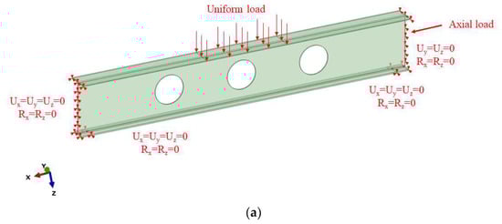

Figure 6.
Diagram of the settings of the numerical simulation: (a) boundary conditions and loads; (b) grid division.
As shown in the figure, Rx, Ry and Rz are the rotational degrees of freedom in the x, y and z directions; Ux, Uy and Uz are the translational degrees of freedom in the x, y and z directions.
3.2. Effect of the Combined Opening Shapes
To investigate the effect of the opening shapes on the load-bearing capacity and buckling behavior of the structures, the experimental phenomena of specimens A and B were compared and verified via numerical simulations. The load–displacement curve for the middle of the stiffener flange is shown in Figure 7. The buckling behavior of the specimens is shown in Figure 8.
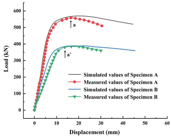
Figure 7.
Diagram of the load–displacement curves of specimens A and B.
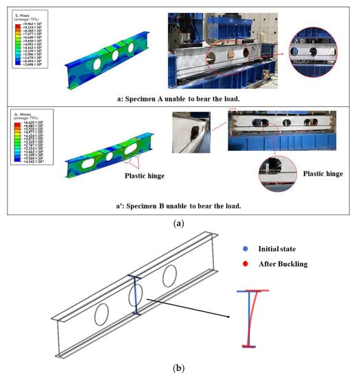
Figure 8.
Diagram of the buckling behaviors of specimens A and B. (a) Numerical and experimental comparison. (b) Deformation form of the middle section of specimen A.
As shown in Figure 7 and Figure 8, due to the difference in the shape of the opening, the load–displacement curves as well as the buckling behavior of the two specimens differed to some extent. As shown in Figure 7, the trends and the extreme values in the load–displacement curves of the two specimens were very different. During the o-a and o-a’ phases, the deformation of the structure increased in small steps as the external load increased linearly. However, the slope of the curve for specimen A was greater, which means that in the elastic phase, the same external load was applied and the deformation occurred more significantly in specimen B. When reaching points a and a’, the specimens could no longer bear the load. At this point, the maximum load that specimen A could bear was 558 kN, while for specimen B, it was 385 kN. Compared with specimen A, the reduction in the maximum load-bearing capacity of specimen B reached 31%.
The buckling behavior of the two specimens was investigated next. For specimen A, due to the small size of the round web openings, the stress transferred smoothly around the round openings, and thus the whole specimen displayed a bending behavior under external loads. When the external load increased, the stiffener web could provide sufficient support for the plate. But due to the large thickness of the stiffener flange, it was hard for the bending moment from the stiffener web to cause great deformation. As a result, a slip in the horizontal direction occurred in the middle of the stiffener web and plate. The deformation form of the middle section of specimen A is shown in Figure 9b. For specimen B, like specimen A, the middle of the stiffener web and plate also displayed a degree of slip in the horizontal direction under the action of the bending moment. But unlike specimen A, the lumbar round openings had a bigger opening area, and there were stress concentrations at the corners. As shown in the structure, there was a degree of shearing action at the corner of the opening, and the stiffener flange was bent. As shown in Figure 8a, plastic hinge failure occurred in the plate and stiffener flange near the lumbar round opening.

Figure 9.
Diagram of the surface strain values of point F-G-3 for specimens A and B.
In order to present the effect of the failure mode on the stress distribution in the middle of the stiffener flange, the stresses at point F-G-3 were analyzed. The stress distribution of the two specimens is shown in Figure 9.
As shown in Figure 9, the strain at the measurement point F-G-3 for specimen B was greater. It could be seen that under external loads, the web with round openings was more resistant to loads transmitted from the plate due to the smaller strength loss of the web, and the load-bearing capacity of the structure was greater, while the stiffener flange was subjected to less tensile stress in the middle. When the load limit was reached, the structure showed more instability due to the lateral slip of the middle of the plate and lower bending action of the middle of the stiffener flange. For specimen B, the deformation of the stiffener flange was more pronounced than in specimen A due to the plastic hinge failure at the corner of the lumbar round openings. The instability of the specimen was moderate compared to specimen A, and the tensile stress at point F-G-3 was slightly higher. It could be seen that the bending effect for specimen B was more pronounced in the middle of the stiffener flange.
3.3. Effect of the Initial Crack Defects
In actual scenarios, localized cracks may occur in the girder structure due to manufacturing defects and harsh service conditions. Under extreme conditions, tearing failure may occur at the crack. To investigate the effect of initial crack defects on the load-bearing capacity and buckling behavior of the structures, the experimental phenomena of specimens B and C were compared. In this section, human damage was inflicted on the middle of the lower wing to simulate the conditions in which a crack would exist. The dimensions and physical appearance of the damage are shown in Figure A3 in Appendix A. Due to the initial crack in the middle of the stiffener flange of specimen C, it was not possible to arrange the displacement gauge; therefore, the data from the displacement transducer of the servo actuator were chosen for comparison. The load–displacement curve for the middle of the stiffener flange is shown in Figure 10. The buckling behavior of specimen C is shown in Figure 11.
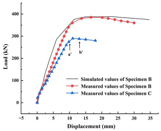
Figure 10.
Diagram of the load–displacement curves of specimens B and C.
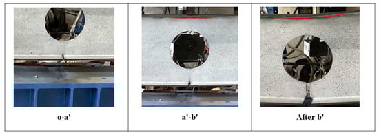
Figure 11.
Diagram of the failure process of specimen C.
As shown in Figure 10, the trends and extreme values in the load–displacement curves of the two specimens were very different. Compared to specimen B, the presence of the initial crack made specimen C more prone to vertical deformation. The ultimate load that the structure of specimen C could bear was 290 kN, with a reduction of 25% compared to the 385 kN of specimen B.
In addition, there was considerable variation in the form of the failure of specimen C. When analyzed in conjunction with Figure 10 and Figure 11, the vertical displacement of specimen C increased linearly with the increase in the external load during the o-a’ phase. During this phase, the width of the initial crack on the stiffener flange gradually increased, and no significant deformation occurred in the stiffener web and plate. For the a’-b’ phase, there was a small increase in the load-bearing capacity of the structure, but the vertical deformation increased significantly. As shown in the actual structure, the stiffener web tore from the crack in the stiffener flange, gradually expanding towards the lower edge of the round opening. At this point, it was accompanied by the distinct tearing of the steel plate. The plate at the top of the round opening showed no significant bending. For the phase after point b’, the structure could not bear more load, the data recorded by the load sensor decreased and the vertical deformation of the structure became noticeably bigger. The stiffener web was completely torn below the round opening. The plate was bent under external loads, and the phenomenon of plastic hinge failure occurred.
3.4. Effect of the Strengthening Stiffeners
In Section 3.2, specimens A and B were unstable due to the lateral slip of the plate and failure to bear more load. In actual ships, the structure is often strengthened by means of welding ribs where the load is concentrated. To investigate the effect of the strengthening stiffeners on the load-bearing capacity and buckling behavior of the structures, the experimental phenomena of specimens B and D were compared and verified via numerical simulations. The load–displacement curve for the middle of the stiffener flange is shown in Figure 12. The buckling behavior of specimen D is shown in Figure 13.
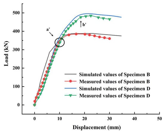
Figure 12.
Diagram of the load–displacement curves of specimens B and D.
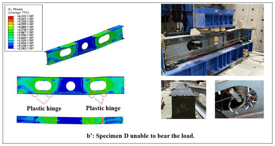
Figure 13.
Diagram of the buckling behavior of specimen D.
As shown in Figure 12, due to the reinforcing effect of the stiffeners on the structures, there was significant variation in the ultimate load and buckling form of specimens B and D. The ultimate load that the structure of specimen D could bear was 484 kN, with a reduction of 25% compared to the 385 kN of specimen B.
As shown in the load–displacement curve, during the o-a’ phase the two specimens displayed similar trends of vertical deformation. As the external load increased, the vertical deformation of the two specimens increased linearly. However, when the external load reached 365 kN (point a’), the following form of deformation of the two specimens differed. As analyzed in Section 3.2, a lateral slip in the middle of the plate occurred in specimen B, and the structure became unstable and was unable to bear more load. But for specimen D, due to the lateral slip of the structure being restrained by the stiffeners, no premature instability of the structure occurred. Therefore, in the load–displacement curve, the displacement increased linearly to point b’ as the external load increased. During the phase after b’, the value of the load sensor decreased rapidly, and the structure displayed significant vertical deformation. Significant wavy deformation occurred in the steel plates around the lumbar round opening corners (as shown in Figure 13). In addition, the magnitude of the lateral slip in the middle of the plate was significantly smaller compared to that of specimen B. Plastic hinge failure was evident at the corner of both lumbar round openings (as the area marked by red circles in Figure 13). The central area of the girder was restrained by the stiffeners, forming a frame structure around the round openings. When the structure buckled, significant vertical displacement occurred in this frame area.
In order to present the effect of the failure mode on the stress distribution in the middle of the stiffener flange, the stresses at point F-G-3 were analyzed. The stress distribution of the two specimens is shown in Figure 14.
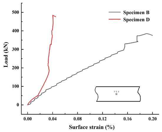
Figure 14.
Diagram of the surface strain values of points F-G-3 for specimens B and D.
As shown in Figure 14, the strain at the measurement point F-G-3 for specimen B was greater. It could be seen that due to the restraint of the ribs, specimen D was subjected to significantly less tensile stress than specimen B in the middle of the stiffener flange. When analyzed in conjunction with the buckling behavior, the stiffeners formed a complete frame structure around the round opening, resulting in local self-restraint. Therefore, as the external load increased, the specimen displayed an overall vertical displacement in the region that was restrained by stiffeners, and the plastic hinge failure phenomenon occurred at the lumbar round openings. The deformation energy of the specimen was released from the plastic hinge bend of the steel plate and the wavy deformation around the corner of the lumbar round openings, and the strain values measured at point F-G-3 were much smaller than those of specimen B.
3.5. Effect of the Stiffener Web Height
In Section 3.2, specimens A and B were unstable due to the lateral slip of the plate and failure to bear more load. Formally, due to its high stiffener web height, the lateral slip in the middle of the plate was exacerbated to some extent, causing instability in the structure. In contrast, in common ships (bulk carriers, tankers, etc.), the stiffener web height of the girder is usually smaller (about half that of passenger ships). To investigate the effect of the stiffener web height on the load-bearing capacity and buckling behavior of the structures, the experimental phenomena of specimens B and E were compared and verified via numerical simulations. The load–displacement curve for the middle of the stiffener flange is shown in Figure 15. The buckling behavior of specimen E is shown in Figure 16.

Figure 15.
Diagram of the load–displacement curves of specimens B and E.

Figure 16.
Diagram of the buckling behavior of specimen E.
As shown in Figure 15, due to the reduced height of the stiffener web of specimen E, the cross-sectional area was smaller, and the load-bearing capacity for external loads was significantly reduced. In the initial phase of loading, specimen E displayed greater vertical deformation for the same load. When the external load reached 219 kN, the structure buckled and could not bear any more load. Compared to the extreme value of specimen B (385 kN), the reduction was 43%. When analyzed concerning the buckling phenomenon in Figure 16, the vertical deformation as well as the lateral slip of the plate increased significantly when the load reached point a’. In addition, a relatively pronounced plastic hinge failure was produced at the corner of the lumbar round opening (as the area marked by red circles in Figure 16).
In order to present the effect of the failure mode on the stress distribution in the middle of the stiffener flange, the stresses at point F-G-3 were analyzed. The stress distribution of the two specimens is shown in Figure 17.
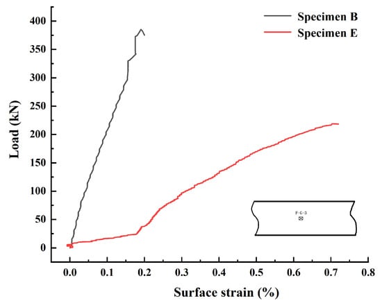
Figure 17.
Diagram of the surface strain values of points F-G-3 for specimens B and E.
As shown in Figure 17, the strain at the measurement point F-G-3 for specimen E was much larger. It could be seen that due to the reduced height of the stiffener web, the structure was more prone to the occurrence of vertical deformation in the central region. As shown in the strain values at the measurement point F-G-3, the strain gauge values increased rapidly with the increase in the external load. This showed that when the stiffener web height was reduced, the vertical deformation in the middle of the specimen under the bending moment was more pronounced. In contrast, for the structures with high stiffener web heights, structural instability due to the lateral slip of the plate occurred more often.
4. Numerical Investigation of the Buckling Behavior of Combined Opening Plate Frame
In the above section, the load-bearing capacity and buckling behavior of combined opening girders with different parameters were investigated mainly by means of experiments combined with numerical simulations, and the reliability of the numerical calculation method was also illustrated. In the investigation above, the deck was mainly selected for the calculations for an area with a slab. In this section, a plate frame structure containing combined opening girders was taken as the object of study, and its buckling behavior was investigated using numerical simulation.
The chosen combined opening frame was from the seventh deck of a passenger ship and consisted of longitudinal girders, stringers and transverses welded together to form the plate frame structure. The physical and model diagrams are shown in Figure 18. The dimensions of the plate frame are shown in Figure A4 in Appendix A.

Figure 18.
Diagram of the structural form of the plate frame: (a) actual view; (b) model view.
In order to simulate the combined loading conditions above the extreme span opening, a 120 mm width area in the middle of the lengthwise plate was loaded. And above the longitudinal girders, two 120 × 120 mm areas were selected for loading. The ends of the longitudinal girders were restrained with fixed ends. After verification of the grid independence, the size of the grid was determined to be 10 mm, and the number of elements was determined to be approximately 300,000. The means of the load application and the form of the boundary conditions are shown in Figure 19.
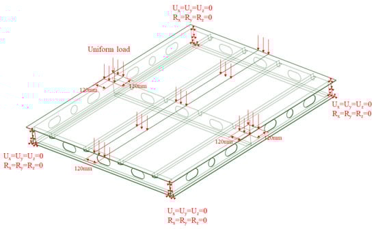
Figure 19.
Diagram of the load application means and boundary conditions.
For comparison, an additional form of plate frame with ribs between the stringers and transverses was introduced. The arrangement of the ribs is shown in Figure A5 in Appendix A. The buckling form and the load-bearing capacity of the two plate frames under external loads were analyzed. The buckling behavior of the two frames is shown in Figure 20.
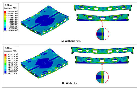
Figure 20.
Diagram of the buckling behaviors of the two plate frames.
As shown in Figure 20, the buckling behavior of the two plate frames was generally similar. For the plate, due to the cross-shape loading pattern, the structure showed a contraction towards the center of the plate. The center formed a shell-shaped low-stress area arranged symmetrically along the length. For the longitudinal girder, plastic hinge failure was evident at the corner of the central lumbar round openings. There was an overall vertical deformation in the area of the middle transverse. For the transverses, the vertical deformation was generated by the external load. In addition, in the middle position, a plastic hinge failure phenomenon in the stiffener flange was observed. For plate frame A, a lateral slip of the stiffener flange also occurred in the middle of the transverses, with large twisting deformations occurring at the plastic hinge. For plate frame B, the overall form of deformation was the same as that of plate frame A. However, due to the support of the ribs, the lateral slip of the stiffener flange in the middle was reduced, and the twisting deformation at the plastic hinge was also reduced. In addition, the ultimate load that plate frame A could bear was 408 kN. Meanwhile, for plate frame B, the addition of the ribs resulted in an ultimate load of 450 kN, with an increase of 10.3%. In addition, the restraint of the ribs provided some improvement in the deformation pattern of the transverses in the event of failure. Therefore, in actual ship structures, the strengthening of the structure could be achieved by adding a reasonable number of ribs in regions where the load is high.
5. Conclusions
A series of numerical simulations and experiments on the load-bearing capacity and buckling behaviors of combined opening girders was conducted, where several affecting factors such as opening shapes, initial crack defects, strengthening measures and stiffener web dimensions were analyzed. On this basis, the ultimate load-bearing capacity and buckling behavior of a plate frame structure on a passenger ship under external loads were simulated using a numerical method. Several observations, conclusions and recommendations are stated based on the investigation results above.
The increase in the stiffener web height significantly changed the buckling behaviors of the combined opening girders. When the stiffener web height was low, the structure exhibited a combination of vertical deformation in the mid-span and lateral slip of the plate. For specimens with a higher stiffener web height, the structure was more likely to exhibit a lateral slip of the plate, causing structural instability, with surface stresses much lower than the strength limit of the material.
For specimens with a high stiffener web height, the lumbar round opening structure showed stress concentrations at the corner near the middle of the girder, with wavy deformation of the steel plate around the openings and plastic hinge failure of the stiffener flange. However, due to the dissipation of energy by local deformation, the lateral slip instability of the structure was mitigated compared to the specimen with a round opening.
With the addition of specimens, during the linear phase the structure exhibited more vertical deformation, and the stiffeners had little effect on the deformation pattern of the structure. When reaching the point of instability of the original structure, the stiffeners effectively limited the lateral movement of the structure. When the structure buckled, it exhibited plastic hinge failure at the intersection of the lower edge of the stiffeners and the stiffener flange. The instability phenomenon of the structure was greatly improved, and the load-bearing capacity was significantly increased.
The finite element method was used to simulate the buckling behavior of the specimens in the experiment, and it is concluded that the finite element modeling predicted elastic and inelastic behavior well and allowed us to assess the ultimate load capacity with reasonable/acceptable accuracy. After applying the finite element method to the simulation of the load-bearing capacity and buckling behavior of the combined opening plate girders, the results showed that the reasonable installation of ribs limited the local instability of the transverse and longitudinal girders and improved the load-bearing capacity of the plate frame structure to a certain extent (around 10%).
Author Contributions
Conceptualization, C.C., H.Z., X.G. and X.X.; methodology, C.C., X.G. and X.X.; software, C.C. and Z.L.; investigation, C.C. and Z.L.; resources, H.Z.; writing—original draft preparation, C.C.; writing—review and editing, C.C. and H.Z.; visualization, H.Z.; supervision, H.Z.; project administration, X.X. and H.Z.; funding acquisition, H.Z. All authors have read and agreed to the published version of the manuscript.
Funding
This research was funded by the Postgraduate Research & Practice Innovation Program of Jiangsu Province (KYCX22_3838).
Data Availability Statement
The data used to support the findings of this study are available from the corresponding author upon request.
Acknowledgments
The authors would like to acknowledge the financial support provided by the Postgraduate Research & Practice Innovation Program of Jiangsu Province (KYCX22_3838) as well as Shanghai Waigaoqiao Shipbuilding Co., Ltd., and China Shipbuilding Cruise Technology Development Co Ltd. for their support in conducting the relevant experiments.
Conflicts of Interest
The authors declare no conflict of interest.
Appendix A
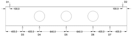
Figure A1.
Diagram of the arrangement of the displacement gauges (mm).

Figure A2.
Diagram of the arrangement of the strain gauges and rosettes.
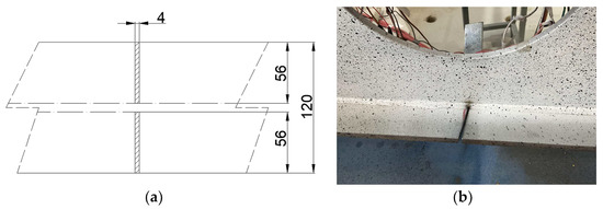
Figure A3.
Diagram of the size dimensions and physical appearance of the damage: (a) dimensions (mm); (b) physical appearance.
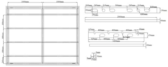
Figure A4.
Diagram of the plate frame dimensions (mm).
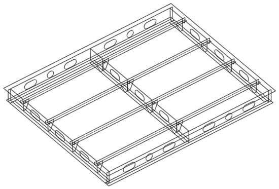
Figure A5.
Diagram of the structural form of the plate frame with ribs.
References
- Andric, J.; Prebeg, P.; Palaversa, M.; Zanic, V. Influence of different topological variants on optimized structural scantlings of passenger ship. Mar. Struct. 2021, 78, 102981. [Google Scholar] [CrossRef]
- Yang, B.; Pei, Z.; Wu, W. Stress-distribution characteristics of cruise ship based on multiple-beam method. Ocean. Eng. 2022, 266, 112646. [Google Scholar] [CrossRef]
- Liu, B.; Yao, X.; Lin, Y.; Wu, W.; Guedes Soares, C. Experimental and numerical analysis of ultimate compressive strength of long-span stiffened panels. Ocean. Eng. 2021, 237, 109633. [Google Scholar] [CrossRef]
- Zhang, Z.; Gan, J.; Guo, G.; Wu, W. Research on the buckling characteristics of opening high web plate frame structures for large cruise ships. China Shipbuild. 2022, 63, 15–23. [Google Scholar]
- Zheng, H.; Qiao, H.; Chen, Y.; Yang, B.; Zhu, B.; Lai, L. Study on anti-progressive collapse performance of cellular steel frames with different web opening shapes. Structures 2023, 47, 338–357. [Google Scholar] [CrossRef]
- Peng, Y.; Kong, Z.; Dinh, B.H.; Nguyen, H.-H.; Cao, T.-S.; Papazafeiropoulos, G.; Vu, Q.-V. Web Bend-Buckling of Steel Plate Girders Reinforced by Two Longitudinal Stiffeners with Various Cross-Section Shapes. Metals 2023, 13, 323. [Google Scholar] [CrossRef]
- Sujitha, R.; Sunmathi, N.; Manikandan, R.K.; Arunprasad, J.; Rajkumar, S.; Sharma, S.; Sharma, K.; Li, C.; Tag Eldin, E.M. Analytical and Experimental Study on Cold-Formed Steel Built-Up Sections for Bending. Materials 2022, 15, 7140. [Google Scholar] [CrossRef]
- Brown, C.J.; Yettram, A.L. The elastic stability of square perforated plates under combinations of bending, shear and direct load. Thin-Walled Struct. 1986, 4, 239–246. [Google Scholar] [CrossRef]
- Brown, C. Elastic buckling of perforated plates subjected to concentrated loads. Comput. Struct. 1990, 36, 1103–1109. [Google Scholar] [CrossRef]
- Shakerley, T.; Brown, C. Elastic buckling of plates with eccentrically positioned rectangular perforations. Int. J. Mech. Sci. 1996, 38, 825–838. [Google Scholar] [CrossRef]
- Wang, G.; Sun, H.; Peng, H.; Uemori, R. Buckling and ultimate strength of plates with openings. Ships Offshore Struct. 2009, 4, 43–53. [Google Scholar] [CrossRef]
- Shanmugam, N.E.; Thevendran, V.; Tan, Y.H. Design formula for axially compressed perforated plates. Thin-Walled Struct. 1999, 4, 1–20. [Google Scholar] [CrossRef]
- Shanmugam, N.E.; Lian, V.T.; Thevendran, V. Finite element modelling of plate girders with web openings. Thin-Walled Struct. 2002, 40, 443–464. [Google Scholar] [CrossRef]
- El-Sawy, K.M.; Nazmy, A.S.; Martini, M.I. Elasto-plastic buckling of perforated plates under uniaxial compression. Thin-Walled Struct. 2004, 42, 1083–1101. [Google Scholar] [CrossRef]
- Paik, J.K. Ultimate strength of perforated steel plates under edge shear loading. Thin-Walled Struct. 2007, 45, 301–306. [Google Scholar] [CrossRef]
- Paik, J.K. Ultimate strength of steel plates with a single circular hole under axial compressive loading along short edges. Ships Offshore Struct. 2007, 2, 355–360. [Google Scholar] [CrossRef]
- Paik, J.K. Ultimate strength of perforated steel plates under combined biaxial compression and edge shear loads. Thin-Walled Struct. 2008, 46, 207–213. [Google Scholar] [CrossRef]
- Saad-Eldeen, S.; Garbatov, Y.; Soares, C.G. Strength Assessment of Wash Plates Subjected to Combined Lateral and Axial. In Maritime Technology and Engineering; Taylor & Francis Group: London, UK, 2015; pp. 553–564. [Google Scholar]
- Saad-Eldeen, S.; Garbatov, Y.; Soares, C.G. Experimental investigation on the residual strength of thin steel plates with a central elliptic opening and locked cracks. Ocean Eng. 2016, 115, 19–29. [Google Scholar] [CrossRef]
- Saad-Eldeen, S.; Garbatov, Y.; Soares, C.G. Experimental strength analysis of steel plates with a large circular opening accounting for corrosion degradation and cracks subjected to compressive load along the short edges. Mar. Struct. 2016, 48, 52–67. [Google Scholar] [CrossRef]
- Saad-Eldeen, S.; Garbatov, Y.; Soares, C.G. Experimental compressive strength analyses of high tensile steel thin-walled stiffened panels with a large lightening opening. Thin-Walled Struct. 2017, 113, 61–68. [Google Scholar] [CrossRef]
- Saad-Eldeen, S.; Garbatov, Y.; Soares, C.G. Buckling collapse tests of deteriorated steel plates with multiple circular openings. Ocean Eng. 2019, 172, 523–530. [Google Scholar] [CrossRef]
- Saad-Eldeen, S.; Garbatov, Y.; Soares, C.G. Experimental failure assessment of high tensile stiffened plates with openings. Eng. Struct. 2020, 206, 110–121. [Google Scholar] [CrossRef]
- Moen, C.D.; Schafer, B.W. Elastic buckling of thin plates with holes in compression or bending. Thin-Walled Struct. 2009, 47, 1597–1607. [Google Scholar] [CrossRef]
- Chung, K.F.; Liu, C.H.; Ko, A.C.H. Steel beams with large web openings of various shapes and sizes: An empirical design method using a generalised moment-shear interaction curve. J. Constr. Steel Res. 2003, 59, 1177–1200. [Google Scholar] [CrossRef]
- Chung, K.F.; Liu, C.H.; Ko, A.C.H. Investigation on Vierendeel mechanism in steel beams with circular web openings. J. Constr. Steel Res. 2001, 57, 467–490. [Google Scholar] [CrossRef]
- Yingjiang, Z.; Renjun, Y.; Hongxu, W. Experimental and numerical investigations on plate girders with perforated web under axial compression and bending moment. Thin-Walled Struct. 2015, 97, 199–206. [Google Scholar] [CrossRef]
- Yingjiang, Z.; Renjun, Y.; Hongxu, W. Experimental Studies of Failure Behavior and Strength of H Beams with Stiffened Web Openings under Compression and Bending Loads. J. Ship Mech. 2016, 20, 315–322. [Google Scholar]
- Shen, W.; Zhao, Y.; Li, L.; Qiu, Y.; Liu, E. Assessment of residual ultimate strength on plate girders with web opening under compression-bending loadings. Ocean Eng. 2019, 187, 106147. [Google Scholar] [CrossRef]
- GB-T 228.1-2021; Tensile Testing of Metallic Materials Part 1: Room Temperature Test Method. National Standardization Management Committee: Beijing, China, 2021.
- Dieffenbach, T.; Treutler, K.; Wesling, V. High-speed tensile tests on high-manganese steel at low temperatures. Mater. Test. 2023, 65, 124–133. [Google Scholar] [CrossRef]
Disclaimer/Publisher’s Note: The statements, opinions and data contained in all publications are solely those of the individual author(s) and contributor(s) and not of MDPI and/or the editor(s). MDPI and/or the editor(s) disclaim responsibility for any injury to people or property resulting from any ideas, methods, instructions or products referred to in the content. |
© 2023 by the authors. Licensee MDPI, Basel, Switzerland. This article is an open access article distributed under the terms and conditions of the Creative Commons Attribution (CC BY) license (https://creativecommons.org/licenses/by/4.0/).