Article

The Effect of Cooling Temperature on Microstructure and Mechanical Properties of Al 6061-T6 Aluminum Alloy during Submerged Friction Stir Welding

1
Department of Mechatronics Engineering, Sanjivani College of Engineering, Savitribai Phule Pune University, Kopargaon 423603, India
2
Department of Mechanical Engineering, School of Technology, Pandit Deendayal Energy University, Raysan, Gandhinagar 382007, India
3
Department of Mechanical Engineering, Escuela Superior de Ingenieros, University of the Basque Country, Alameda de Urquijo s/n, 48013 Bilbao, Spain
*
Authors to whom correspondence should be addressed.
Metals 2023, 13(7), 1159; https://doi.org/10.3390/met13071159
Submission received: 19 May 2023 / Revised: 12 June 2023 / Accepted: 21 June 2023 / Published: 22 June 2023

Abstract

:
Submerged friction stir welding (SFSW) is a new modification of friction stir welding. In this paper, 6 mm thick 6061Al-T6 alloy plates were welded using the friction stir technique under normal air and submerged water conditions at 108 mm/min welding speeds and a rotational rate of 900 rpm. The cooling water temperature in SFSW varied at 0 °C, 35 °C, and 80 °C to clarify the effect of water temperature. The characteristic hourglass-shaped stir zone was observed in the macrostructure of all the samples. All the samples exhibited defect-free joints. The results revealed that the finer grain size of 2.43 μm was at 0 °C. The macrostructure of SFSW joints separated into the shoulder-driven zone and pin-driven zone due to the low-temperature difference between the environment and water media and the high heat absorption capacity of the water, which caused a more substantial cooling rate during water-submerged welded joints. The microhardness distribution of all the joints showed typical “W” shape characteristics. The microhardness for all submerged samples was higher than in normal air conditions due to the higher thermal cycling effect in submerged conditions. Improved dynamic recrystallization in the joint welded at 80 °C resulted in the highest tensile strength (~249 MPa) and microhardness (~95 HV).

1. Introduction

Friction stir welding (FSW) is a novel and effective solid-state green welding technology for joining materials. The filler material and cover gas are not required for performing this process. Other advantages include no fumes, no arc, less energy consumption, and less scatter, making the process a sustainable choice for joining in manufacturing [1,2]. Due to friction between the non-consumable tool and workpiece, the joining material undergoes plastic deformation and severe stirring in the FSW process [3,4]. The process occurs below the material’s melting temperature compared to conventional fusion welding processes, in which melting is essential for joining the material. The melting phenomenon followed by solicitation in fusion techniques produces defects in welded components such as solidification cracking, larger heat affected zone, etc. [5,6]. Due to its low-temperature-joining characteristic, the FSW has been explored for joining various similar and dissimilar materials. Despite these advantages of FSW, the thermal cycle involved in FSW causes a dissolution of strengthening precipitates, producing softened joints resulting in poor mechanical characteristics [7,8,9].
The limitations involved in the FSW process give rise to the development of the many variants over time [10]. Submerged friction stir welding (SFSW) is a new modification of FSW to overcome the limitations mentioned earlier. The SFSW involves using water as a coolant to standardize the temperature. Cao et al. [11] investigated the SFSW of AF2507 super duplex stainless steel (SDSS). They reported that the submerged FSW joint had significantly lower residual stress due to the apparent lower welding temperature, which increased the fatigue resistance. Heirani et al. [12] compared the mechanical properties of Al5083 alloy during FSW in room-temperature water and air environment. They observed a higher tensile strength in water-cooled FSW than in air. This was attributed to higher stir zone (SZ) hardness for water-cooled samples. Liu et al. [13] studied underwater FSW using room-temperature water on 2219 aluminum alloy. They reported a higher tensile strength of 341 MPa SFSW compared to the 324 MPa in normal conditions. They also found that fracture in underwater-welded joints occurs at the interface of the nugget zone and the thermomechanically affected zone (TMAZ) on the advancing side (AS), significantly different from the typical joint. Shanavas et al. [14] addressed the feasibility of underwater FSW of AA 5032 H32 alloy using room-temperature water to improve the joining strength. They reported tensile strength of 208.9 MPa in SFSW at 700 rpm and 65 mm/min welding speed. They also noted the absence of a heat-affected zone in underwater welds.
The researchers also investigated dissimilar material-joining using FSW in submerged conditions. Derazkola and Khodabakhshi [15] performed a feasibility study on SFSW of AA5083 aluminum alloy and A441 AISI steel. They used water at 0, 25, and 50 °C. They reported that cooling influenced on inter-mixing of dissimilar metals. They observed a decrease in intermetallic compounds’ (IMCs) layer thickness by decreasing the peak temperature. The room-temperature cooling medium resulted in the best tensile strength of 310 MPa and an elongation of 13%. Mahto et al. [16] presented the feasibility of SFSW between AA6061-T6 and AISI 304 by varying rotation speed. They reported finer grains in SZ, a reduced weld porosity, and a reduced thickness of IMC due to a faster cooling rate. Zhao et al. [17] carried out SFSW of dissimilar 6013 Al alloy and AZ31 Mg alloy at the rotation speed of 1200 rpm and a welding speed of 80 mm/min. They reported a tensile strength of 152.3 MPa, equivalent to 63.3% of the strength of AZ31 Mg alloy. Zhang et al. [18] investigated FSW of dissimilar Al 6061-T6 and pure copper in a lap configuration during the underwater condition. They observed less intermetallic formation in SFSW compared to normal FSW. The diffusion interlayer was 2 µm thick in SFSW and 18 µm in normal FSW. The copper oxidation was prevented in the SFSW condition. Lader et al. [19] presented the viability of weldability between dissimilar brass CuZn40 (CW509L) and AA1100-O alloy. They revealed that the defects, such as cracks, tunnels, voids, etc., were significantly reduced in SFSW. They reported a defect-free joint at a rotation speed of 1400 rpm and a plunge depth of 0.2 mm. The SFSW reduced the formation of thick IMCs due to lower peak temperatures. They also reported improved hardness and thus improved the overall quality of the welded joint in SFSW.
SFSW was also explored to a great extent to understand the influence of process parameters such as rotation speed, welding speed, plunge depth, etc. Liu et al. [20] reported the significance of the welding speed during SFSW of Al 2219 aluminum alloy. They varied welding speeds from 50 to 200 mm/min. They found a narrowing of the softening region in the TMAZ and heat-affected zone (HAZ) with an increase in the welding speed due to a weakening of the precipitate deterioration. Zhang et al. [21] also performed a study to illuminate the effect of rotation speed during SFSW of Al 2219-T6 alloy. They revealed a direct relationship between the SZ’s hardness and rotation speed and attributed this phenomenon to increased dislocation density. The fracture occurred in the SZ for joints welded at a low rotation speed, but the fracture location shifted to TMAZ and HAZ for joints welded at a higher rotation speed. Wakchaure and Thakur [22] developed a mathematical model for underwater FSW of AA 6061-T6 using a stepped pin tool profile. They found results of a mathematical model that were comparable with experimental results. Khalafe et al. [23] systematically reviewed 150 research studies and highlighted FSW parameters and their influence on the quality of the FSW joints for the aluminum alloys in similar and dissimilar material systems. Walz et al. [24] investigated the effect of the stitch seam length on the strength properties of intersecting friction stir welds of EN AW-6016 T4 sheets in a butt configuration. They reported an increase in tensile and fatigue strength over the stitch seam length.
Researchers also explored the modelling of the SFSW and the optimization of the process parameters. Zhang and Liu [25] optimized SFSW of 2219-T6 aluminum alloy using a Box–Behnken design of experiment, considering rotation speed, tool travel speed, and shoulder plunging depth as the process parameters and tensile strength as the response. They found that rotation and welding speed were predominant factors affecting tensile strength. Zhang et al. [26] conducted thermal modeling of SFSW of Al 2219-T6 alloy using a heat transfer model. The rotating speed of the tool, travel speed, and axial force used for modelling were 800 rpm, 100 mm/min, and 4.6 kN, respectively. The SFSW was performed using room-temperature water. They observed that the surface heat flux of the shoulder during the SFSW was higher than during normal FSW. They reported experimental validation for the developed thermal model. Wakchaure and Thakur [27] used a hybrid grey relational analysis–artificial neural network approach to optimize the underwater FSW of AA 6061-T6. They performed thirty experiments to study outputs such as the ultimate tensile strength (UTS), % elongation, and impact strength. They found that the tool rotation speed has a significant effect on the weld characteristics. Menon et al. [28] used a thermomechanical model for developing a relationship between the frictional heat and the weld properties during the SFSW of A441 AISI steel. They reported a lower strain rate for steel in SZ during SFSW than during normal FSW. A higher cooling rate in SFSW resulted in finer grains in SZ. They noted that the tensile strength of the joint welded during SFSW was 20% higher than the normal FSW joint.
The literature study revealed that SFSW is a potential variant of normal FSW to achieve improved joint mechanical properties. The SFSW uses water as the submerging medium because of its high thermal conductivity. The SFSW has been explored to understand the effect of the process parameters, the joining of dissimilar materials, the thermal analysis, and the optimization of the process. The water temperature is one of the significant parameters impacting the joint properties. To the author’s knowledge, no research has been reported to study the effect of water temperature on the mechanical and microstructural properties of the Al 6061-T6 alloy joints. The present study investigated submerged FSW of Al 6061-T6 joining considering different water temperatures of 0 °C, 35 °C, and 80 °C. Liu et al. [29] investigated the effect of water temperatures from 15 to 75 °C with a spacing of 15 °C. For the present study, the authors attempted to study the impact of water temperature using a wide range of cooling water temperatures. The 0 °C temperature was selected because the freezing point of water is 0 °C, making it the lowest temperature at which water is available. The room-temperature water was available at 35 °C. Hence 35 °C temperature was one of the choices for water temperature. The maximum water temperature reported in the earlier literature was 75 °C. Thus, the authors selected a maximum water temperature of 80 °C for the present study. Further, the results were compared with normal FSW.

2. Materials and Methods

This study analyzed Al 6061-T6 with a thickness of 6 mm as the base material (BM). The chemical composition of the BM is presented in Table 1. The plates of 200 mm in length and 75 mm in width were cut using a wire cut machine. The samples were adequately cleaned using acetone before use and further clamped in the fixture. The container was filled with water so that the tool remained submerged in water. The experiment setup is shown in Figure 1.
The experiments were performed at three different water temperatures, 0 °C, 35 °C and 80 °C, and designated as cold water SFSW (WC), room water SFSW (WR), and hot water SFSW (WH), respectively. One set of experiments was performed in normal air FSW conditions (IA). All the experiments were conducted along the rolling direction of the plates on a conventional milling machine. The experiments were performed with a rotation speed of 900 rpm, 108 mm/min welding speed, and a tilt angle of 2°. The process parameters were selected based on the previous literature and preliminary trials. The conical-shaped tool of H13 tool steel with an 18 mm shoulder and a 6 mm pin diameter was used for experimental tests. The tool used for the experiments is shown in Figure 1b.
The specimens, after experiments, were cross-sectioned using a wire cut machine. Further, the cut samples were polished. Next, Keller’s reagent (HNO3:HF:HCl:H2O = 2.5:1:1.5:95 vol.%) was used to etch the samples for the metallographic study. The microstructure of the welds was characterized using optical microscopy (Olympus GX51, Tokyo, Japan). The Electron Backscatter Diffraction (EBSD) (JEOL, Tokyo, Japan; Model: 6500F) was used to measure grain size in the stir zone of the weld joints. The microhardness measurements were conducted using Vickers microhardness equipment (Innovatest Europe BV NEXUS 4302, Maastricht, Netherlands). The microhardness was measured along the centerline of the samples. The interval of 1 mm was maintained, keeping the load of 300 g for a dwell time of 10 s. The tensile test specimens were cut according to ASTM E8-E8M with a Concord WEDM machine DK7732 (Concord Limited, Bangalore, India). The tensile test was performed on a computer-assisted universal testing loading instrument (FSA FSA/M-100, S. M. Engineers, Pune, Maharashtra, India) at the strain rate of 1 × 10⁻³ s−1 at room temperature.

3. Results and Discussion

3.1. Macrostructure Evolution of the Joints

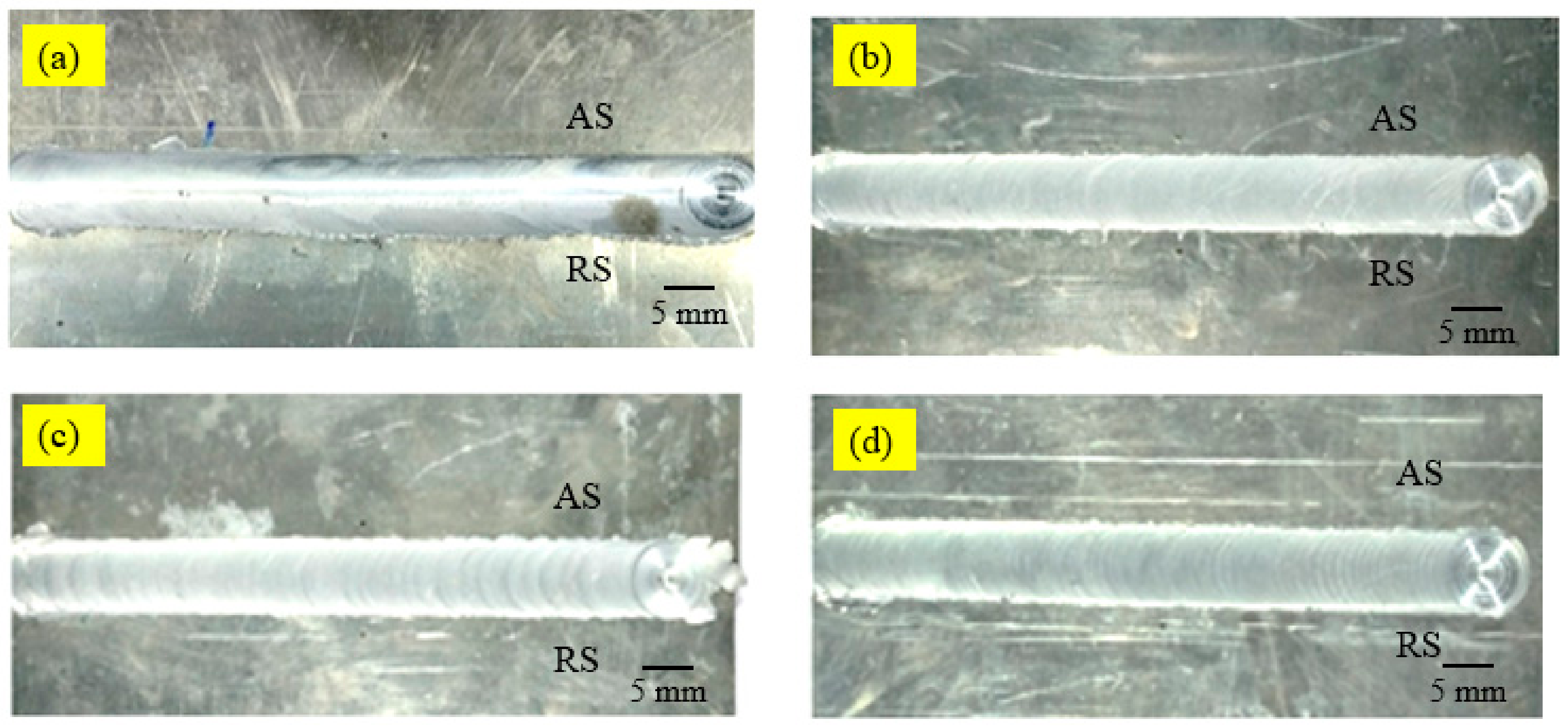
The surface morphologies of the welds under different water temperatures are presented in Figure 2. The samples observed are free from surface abnormalities such as cracks, grooves, open tunnels, etc. The top surfaces of all SFSW specimens are noted with rough circular marks of the shoulder, while the IA specimen exhibited a smooth top surface. The rough marks on the SFSW samples are caused by the faster cooling from the water, which can restrict the flow ability of the plasticized material near the tool, resulting in a rough surface [30].
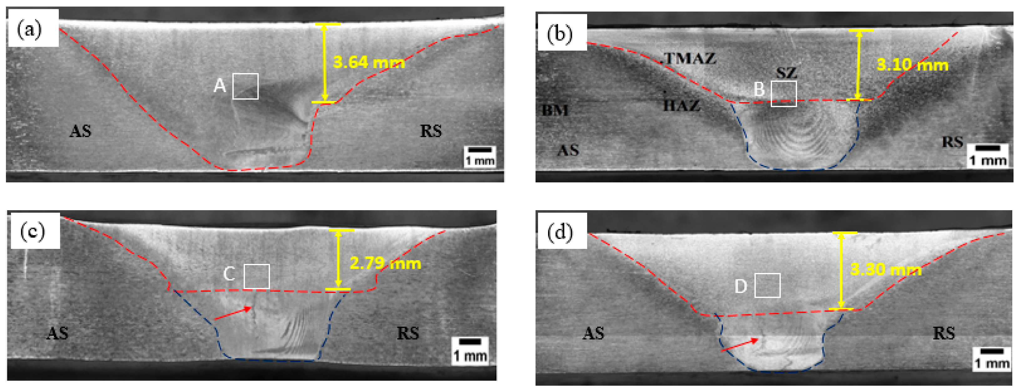
The macrostructure of all the submerged friction-stir-welded joints and IA joints is shown in Figure 3. The characteristic hourglass-shaped SZ was observed in the macrostructure of all the samples. All the joints were observed without any internal defects; the microstructure comprised four zones: SZ, TMAZ, HAZ, and BM. The different zones are shown in representative Figure 3b. The boundaries of the weld zone and BM can be clearly distinguished in all the cross sections on the AS. The joints’ retreating side (RS), except WH, as can be seen, is diffused. The diffused RS is attributed to a lower strain rate due to the opposite direction of torsion and the circumventing velocity fields on RS compared to the advancing side (AS) [31]. However, RS of WH is sharp, as can be seen, which differs from the earlier literature. The sharp RS can be attributed to a balanced strain rate on AS and RS during WH joints.
The SFSW joints’ macrostructure is separated into shoulder-driven (SDZ) and pin-driven (PDZ) zones. SDZ is the zone produced due to pressure and friction heat between the shoulder and the surface of the workpiece above the weld nugget. The SDZ and PDZ are highlighted with red and blue dotted lines, respectively, as shown in Figure 3b–d. Such distinct separation has not been observed in IA joints. This observation can be related to the low temperature difference between the environment and water media and the high heat absorption capacity of the water, which caused a more substantial cooling rate for water-submerged welded joints [32]. The difference between the environment and air media was high in IA joints, allowing heat penetration through the thickness to a deep scale. Hence, such separated zones were not identified in IA joints. SDZ for WC joints was found to be 2.79 mm, the lowest among all the SFSW joints. This is due to the lowest temperature difference. WH joint exhibited the highest SDZ of 3.30 mm among SFSW joints.

3.2. Microstructure Analysis through EBSD

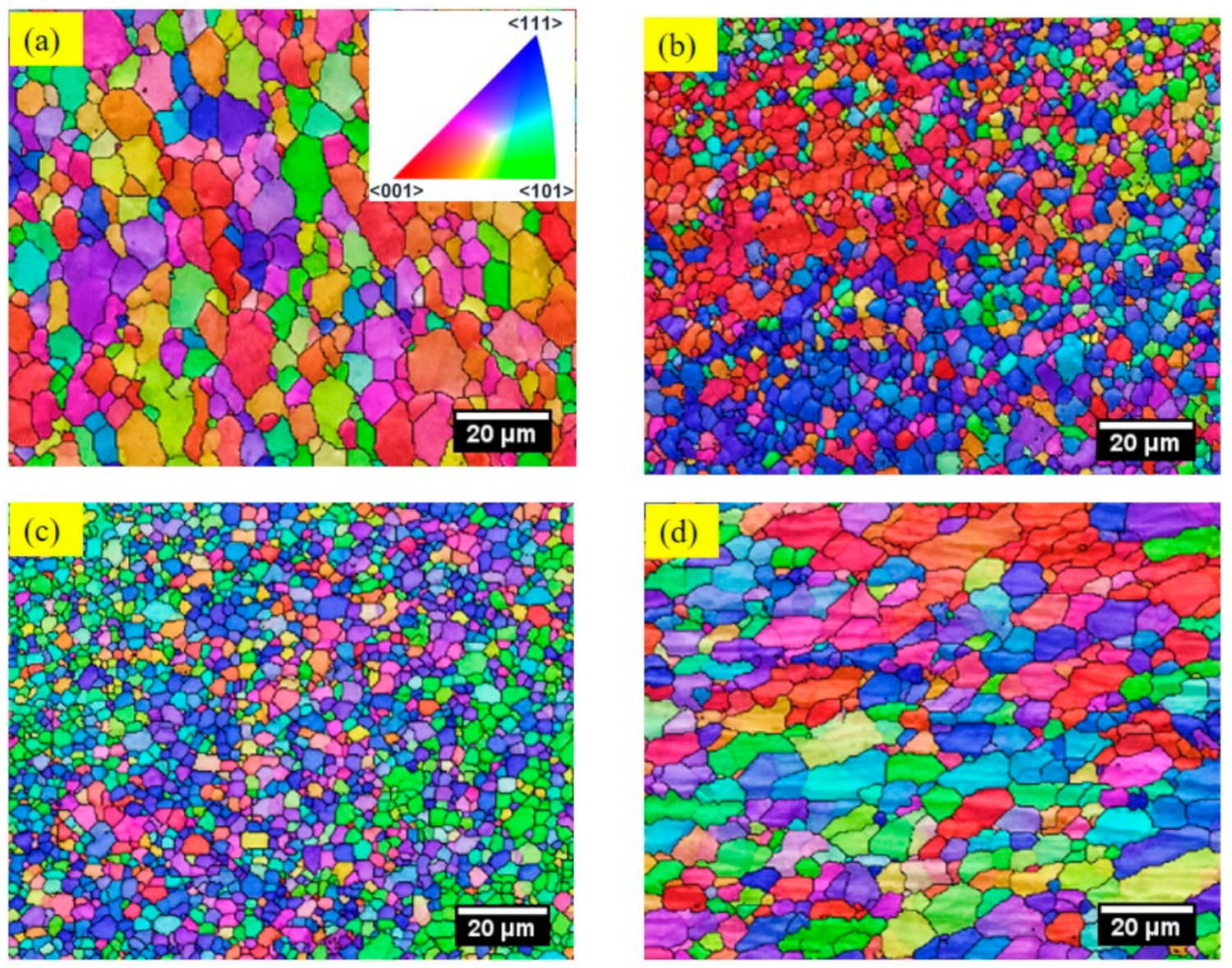
Figure 4 shows the EBSD maps of grain morphologies in the SZ of the joints. The grain evolution has been an essential issue for FSW since it significantly affects the tensile behavior of the sample. The selected zones are highlighted with white boxes, as shown in Figure 3.
The equiaxed recrystallized grains can be seen in all the SZs. This can be attributed to the severe stirring of the material in SZ, producing several dislocations. Due to the high dislocation density and the stress imbalance in the SZ, the grain boundaries experience movement. This movement is driven by the energy minimization process and the redistribution of stresses within the material. The migration of grain boundaries results in the formation of protrusions or bulges along the boundaries. These protrusions or bulges act as nucleation sites for new grains. When the protrusions are cut and deformed, they provide favorable conditions for the initiation of equiaxed grains in SZ.
Different grain orientations are due to varying flows of plasticized material in the SZ. It is believed in FSW that the material in SZ undergoes various forms of plastic deformation and microstructural changes during the welding process due to the discontinuous and continuous dynamic recrystallization, the dynamic recovery, and the growth of grains [33]. Discontinuous dynamic recrystallization involves the nucleation and growth of new grains, often accompanied by the consumption of existing grains. Continuous dynamic recrystallization, on the other hand, occurs through the migration and formation of new grains along the boundaries of existing grains. Dynamic recovery is a process that occurs concurrently with dynamic recrystallization. It involves the reduction of dislocation density and the rearrangement of dislocations within the material. Dynamic recovery helps to relieve some of the deformation-induced stresses and contributes to the development of a more stable microstructure.
The orientation maps revealed that the IA samples exhibited the average highest grain size (8.1 μm) among all the samples, while the WC sample exhibited the smallest grain size (2.43 μm). This is because the grain size in the stir zone depends on the dominance between the strain rate and the heat input [5]. In the WC sample, the heat input was substantially lower, dominating the strain rate impeding the grain growth and resulting in the fine-grained SZ in the WC sample. Moreover, the smallest grains in the WC samples can be attributed to the rate of cooling. The cooling rate influences the nucleation and growth of different phases or the formation of microstructural features. Slower cooling rates generally allow more time for atoms to rearrange and form larger grains, while faster cooling rates promotes the formation of finer grains. The WR samples exhibited an average grain size of 3.21 μm. The lower heat input and the less complex flow of the plasticized metal in the WR and WC sample SZ indicated smaller grains [34]. The WH samples exhibited an average grain size of 6.1 μm.

3.3. Microhardness Distributions of the Joints

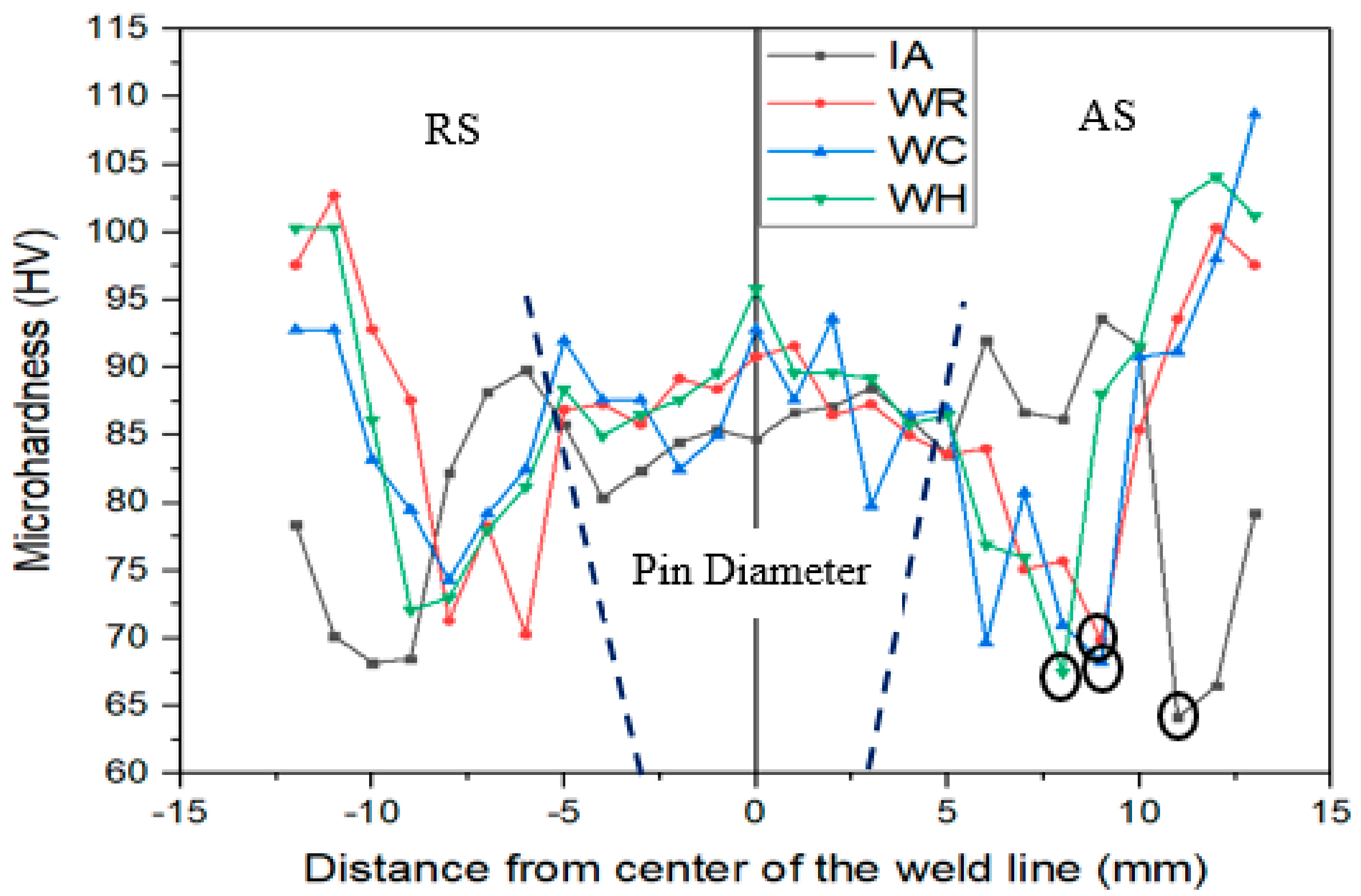
The microhardness distribution is measured in the transverse cross-section of the joints and is plotted as shown in Figure 5. The microhardness of the base material is 107 HV. A characteristic “W” shaped hardness profile was obtained for all the samples. This profile is generally reported for precipitation-hardened aluminum alloys [7]. The microhardness in AS is less than that in RS for all the samples due to the high heat input resulting from a high strain rate on AS compared to RS. The maximum hardness was located at SZ for all the samples. The SZ exhibits fine grains and precipitates due to the stirring process of the tool. These fine grains consist of innumerable grain boundaries that obstruct the dislocation movement during loading, resulting in higher SZ microhardness. Among all the samples, the highest hardness of 95 HV was recorded in the SZ of the WH condition, which can be attributed to the improved thermal cycle in the WH condition exhibiting both preheating and slow cooling processes. The lowest hardness of 62 HV was recorded in the SZ of the IA condition. A noticeable reduction in microhardness was also observed at the interface of TMAZ and HAZ compared to SZ. A softening region with the lowest hardness value was observed at the TMAZ region for SFSW samples.
Contrary to this, TMAZ exhibited higher hardness than HAZ for IA specimens. The observed higher hardness in TMAZ of the IA sample may be due to the abundant dissolved precipitates in TMAZ. These dissolved precipitates may have increased the solute atoms’ concentration which is responsible for precipitation hardening and solid solution strengthening during natural aging. This phenomenon resulted in TMAZ exhibiting a greater hardness than the hardness in HAZ [20].

3.4. Tensile Properties of Joints

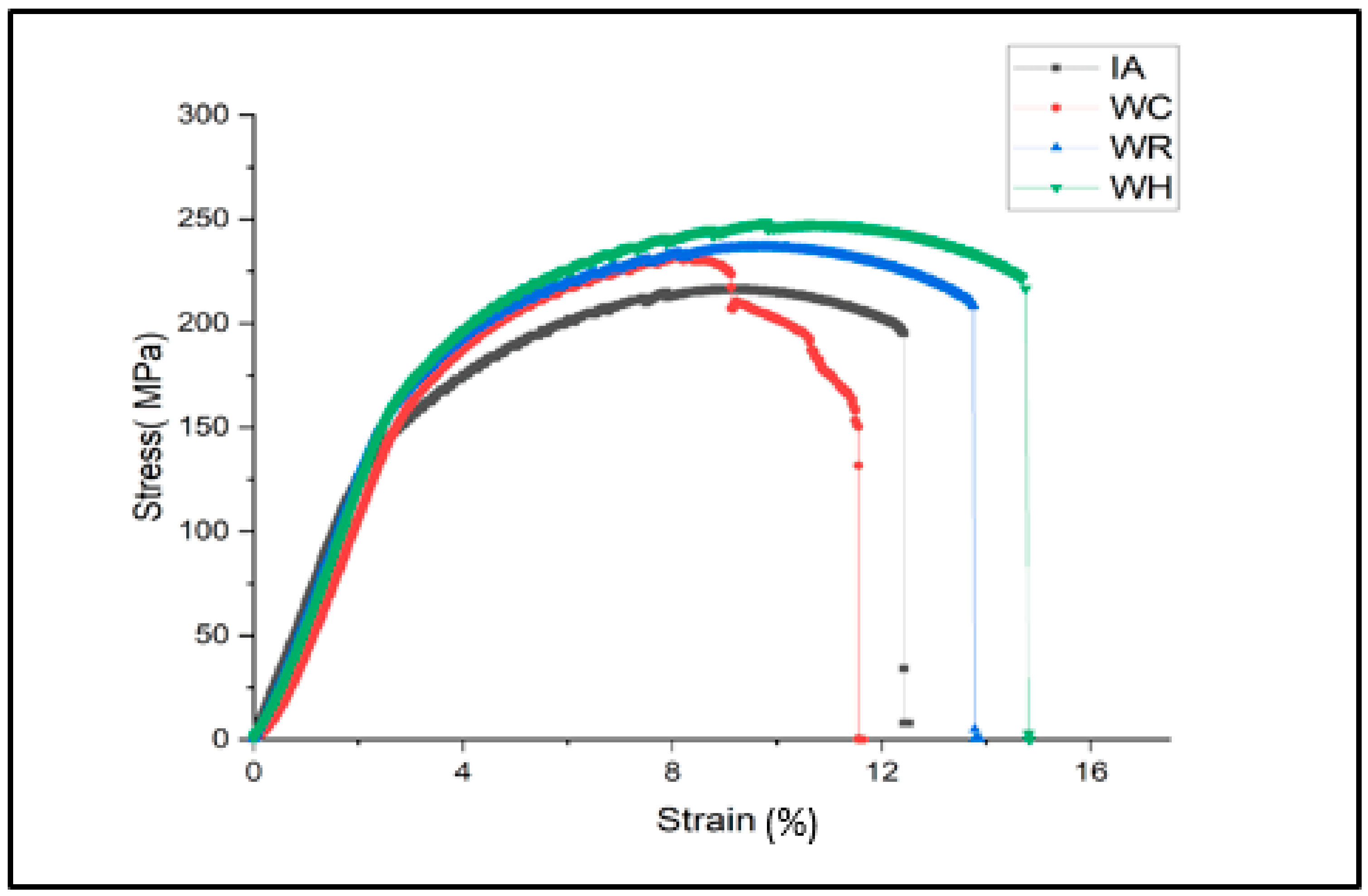
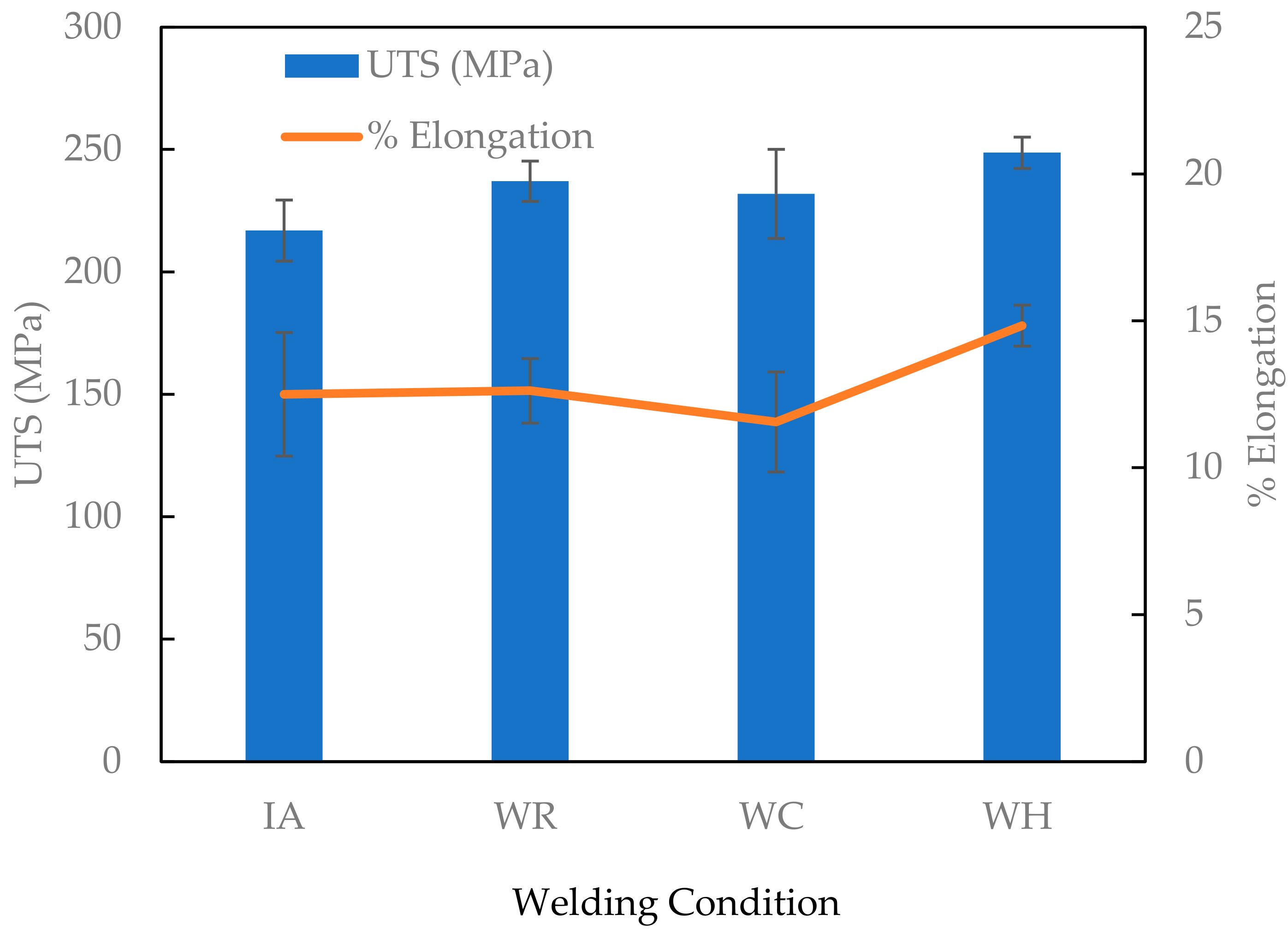
Figure 6 shows the stress-strain curves for the IA, WH, WR, and WH joints. All the friction-stir-welded joints exhibit decreased strength and ductility. A positive trend can be seen between the strength and % elongation of all the SFSW joints and the increasing water temperature. By comparing variations in the tensile strength and % elongation of the submerged welded joints (Figure 7) with ambient-condition-welded joints, it can be summarized that regulating weld temperature distribution increases the weld joint’s strength. The WH samples represented the highest tensile strength of 248.7 MPa, yield strength of 236 MPa, and % elongation of 15% among all the samples.
The highest tensile strength of the WH sample may be due to the presence of strengthening precipitates in hot-water-welded specimens. Fu et al. [32] observed the strengthening precipitates in the nugget zone of hot-water-welded specimens. The age-hardened, heat-treatable aluminum alloys achieve a high strength through the combined strengthening mechanisms of solid solution hardening, grain size control, strain hardening, and precipitation hardening [35]. Though the grain size of the WH specimens is reasonably more than the WC and WR samples, other strengthening mechanisms could have assisted the WH sample in improving its strength. Similar results are reported by Liang et al. [36]. The highest tensile strength of the WH sample also may have attributed to a reduced cooling rate. The welding at higher water temperatures slows down the cooling rate of the weld zone. Slower cooling allows for a more gradual solidification of the material, which help to reduce the formation of undesirable microstructures, such as brittle phases or excessive grain growth, resulting in a higher-strength joint. It can also be due to the improved material flow in WH samples. A higher water temperature softens the material near the weld zone more effectively. This enhanced plasticity facilitates better material flow and mixing during the stirring process. An improved material flow helps in achieving a more homogeneous microstructure and improves joint strength. An improved strength at a higher water temperature has also been reported by Fu et al. [32]. They reported an improvement of tensile strength of 92% of the base metal in hot water (57 °C) compared with the cold water and air-welded samples of the heat-treatable AA 7050. Among all, WH exhibited the highest ductility of 14.84%. When the water is heated, it causes the metal to soften and become more ductile. However, overcooled water joints exhibited the lowest % elongation of 11.56%. This can be attributed to the weld joint hardening due to a lower formation temperature in the weld zone.
All the SFSW samples exhibited higher joint efficiency (JE) than the IA sample. The highest joint efficiency (JE) of 82.1% was found with the WH sample, 10.5% higher than the sample welded with conventional friction stir welding.

3.5. Fractography

The fracture surfaces of the welded joints were examined to determine the underlying mechanisms that led to the failure of the joint. The analysis of the fracture surfaces can provide essential insights into the quality and performance of the welded joint. The lowest hardness region in the sample is mainly susceptible to the fracture location of the FSW joints.
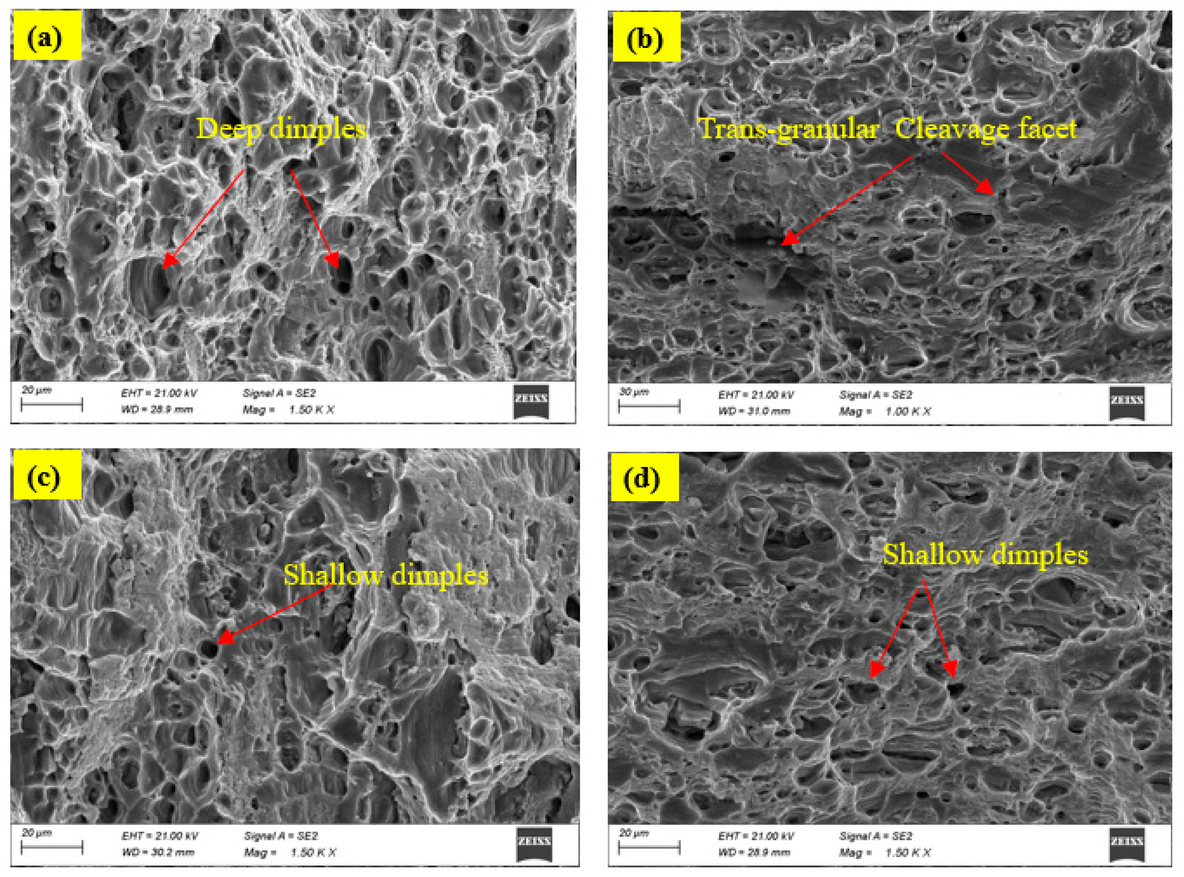
The location of the LHZ in SFSW joints is at the interface of SZ/TMAZ (Figure 5). This interface is highly significant for the initiation of crack and facture of the sample because it is a complex transition region between the zone of dissolution and the zone of overaging. Moreover, this interface transitions between the fine and elongated grains in SZ and TMAZ, respectively. This transition is not smooth in the joints. An abrupt transition between grain microstructures leads to the sample’s fracture location. For the IA joints, the LHZs were in the HAZ mainly due to a slower cooling rate from the air. UFSW involves a complex interplay of forces, temperatures, and pressures. The SEM images of a fractured surface of IA and SFSW samples are shown in Figure 8. The ductile fracture mode can resemble the large dimples, whereas a dimple-free fractured surface indicates a cleavage fracture mode. The SEM of the fractured surface of IA was associated with a more significant number of deep dimples indicating ductile fracture. The larger dimple size in IA highlights a more significant deformation during tensile loading. The SEM images of all SFSW samples represent a combination of a few dimples and dimple-free facets, indicating a mixed failure mode involving cleavage mode of ductile and brittle fractures. The population of dimples and their depth determines the amount of plastic deformation material underwent before the ductile mode of failure. The WH highlights a more dimpled structure among all SFSW samples. A ductile fracture can occur if the water temperature is too high. The higher temperature of the water can lead to more a significant deformation of the metal during the welding process, which can ultimately result in a ductile fracture with high ductility. The SEM morphology of WC shows shallow dimples among all SFSW, indicating less plastic deformation and less ductility.
Cooled water in WC may have caused a rapid cooling of the metal, resulting in thermal stresses that further increase the chances of fracture before substantial elongation. The dimples in the WR specimen with a trans-granular cleavage facet reduced the elongation percentage. The unique river-line pattern joined by shear edges on the trans-granular cleavage facet demonstrates the propagation of the crack. The trans-granular cleavage facet’s presence suggests early crack initiation and consequent sample failure with reduced elongation.

4. Conclusions

This study investigates the microstructure and mechanical characteristics of a friction-stir-welded, 6 mm thick, Al 6061-T6 aluminum alloy using various water temperatures, 0 °C (WC), 35 °C (WR), and 80 °C (WH), and the results are compared with conventional FSW (IA). Based on the results of this study, the following conclusions were drawn:
  • The microhardness distribution of as-welded joints showed a typical “W” shape characteristics under all welding conditions. The highest value of the hardness was 95 HV0.1 at the 80 °C water temperature. The lowest hardness, 62 HV0.1, occurs at the HAZ of the advancing side for IA joints.
  • A fine and balanced microstructure can be found in SZ. The grain size of samples IA, WC, WR, and WH in the SZ is 8.1 μm, 2.43 μm, 3.21 μm, and 6.1 μm, respectively. It was observed that joints welded in a WC condition restricted the grain growth during FSW and showed the smallest grain size. The nugget zones’ grains are smaller in all water cooling media conditions compared to air condition.
  • With the increase of the cooling water temperature, the strength of the welded joint marginally increases. Among the all-weld joints, WH weld joints showed the best mechanical characteristics with an ultimate tensile strength of 82.1% and an elongation of 14%.
  • The ductile mode of fracture was observed in IA weld joints. All SFSW joints indicated a mixed failure mode involving a cleavage mode of ductile and brittle fractures.

Author Contributions

Conceptualization, K.F., R.C. and L.N.L.d.L.; methodology, R.C. and J.V.; software, K.W. and A.T.; validation, K.F. and R.C.; formal analysis, K.W.; investigation, K.W., J.V. and L.N.L.d.L.; resources, K.F. and K.W.; data curation, A.T.; writing—original draft preparation, K.F. and R.C.; writing—review and editing, A.T., J.V. and L.N.L.d.L.; visualization, K.F.; supervision, K.W. and L.N.L.d.L. All authors have read and agreed to the published version of the manuscript.

Funding

This research received no external funding.

Data Availability Statement

Data presented in this study are available in this article.

Conflicts of Interest

The authors declare no conflict of interest.

Nomenclature

ASAdvancing side
BMBase material
FSWFriction stir welding
HAZHeat affected zone
IANormal air FSW
IMCsIntermetallic compounds
PDZPin-driven zone
RSRetreating side
SDZShoulder-driven zone
SFSWSubmerged friction stir welding
SZStir zone
TMAZThermomechanically affected zone
UTSUltimate tensile strength
WCCold water SFSW at 0 °C
WHHot water SFSW at 80 °C
WRRoom water SFSW at 35 °C

References

  1. Rathinasuriyan, C.; Pavithra, E.; Sankar, R.; Kumar, V.S.S. Current Status and Development of Submerged Friction Stir Welding: A Review. Int. J. Precis. Eng. Manuf. Green Technol. 2021, 8, 687–701. [Google Scholar] [CrossRef]
  2. Rodríguez, A.; Calleja, A.; López de Lacalle, L.N.; Pereira, O.; González, H.; Urbikain, G.; Laye, J. Burnishing of FSW aluminum Al–Cu–Li components. Metals 2019, 9, 260. Available online: https://www.mdpi.com/2075-4701/9/2/260 (accessed on 21 February 2019). [CrossRef] [Green Version]
  3. Rathinasuriyan, C.; Kumar, V.S.S. Optimisation of submerged friction stir welding parameters of aluminium alloy using RSM and GRA. Adv. Mater. Process Technol. 2021, 7, 696–709. [Google Scholar] [CrossRef]
  4. Vivas, J.; Fernández-Calvo, A.I.; Aldanondo, E.; Irastorza, U.; Álvarez, P. Friction Stir Weldability at High Welding Speed of Two Structural High Pressure Die Casting Aluminum Alloys. J. Manuf. Mater Process 2022, 6, 160. [Google Scholar] [CrossRef]
  5. Fuse, K.; Badheka, V. Bobbin tool friction stir welding: A review. Sci. Technol. Weld. Join 2019, 24, 277–304. [Google Scholar] [CrossRef]
  6. López de Lacalle, L.N.; Urbikain Pelayo, G.; Azkona, I.; Verbiţchi, V.; Cojocaru, R.; Boţilă, L.N.; Ciucă, C.; Perianu, I.A.; Vlascici, M. Functional layers of aluminium alloy on steel made by alternative friction processes, for elements of metal structures. In Advanced Materials Research; Trans Tech Publications Ltd: Bäch, Switzerland, 2018; Volume 1146, pp. 106–114. Available online: https://www.scientific.net/AMR.1146.106 (accessed on 10 April 2018).
  7. Wahid, M.A.; Khan, Z.A.; Siddiquee, A.N.; Shandley, R.; Sharma, N. Analysis of process parameters effects on underwater friction stir welding of aluminum alloy 6082-T6. Proc. Inst. Mech. Eng. B J. Eng. Manuf. 2019, 233, 1700–1710. [Google Scholar] [CrossRef]
  8. Wahid, M.o.h.d.A.; Khan, Z.A.; Siddiquee, A.N. Review on underwater friction stir welding: A variant of friction stir welding with great potential of improving joint properties. Trans Nonferrous Met. Soc. China 2018, 28, 193–219. [Google Scholar] [CrossRef]
  9. Sánchez Egea, A.J.; Rodríguez, A.; Celentano, D.; Calleja, A.; López de Lacalle, L.N. Joining metrics enhancement when combining FSW and ball-burnishing in a 2050 aluminium alloy. Surf. Coat. Technol. 2019, 367, 327–335. [Google Scholar] [CrossRef] [Green Version]
  10. Ahmed, M.M.Z.; El-Sayed Seleman, M.M.; Fydrych, D.; Çam, G. Friction Stir Welding of Aluminum in the Aerospace Industry: The Current Progress and State-of-the-Art Review. Materials 2023, 16, 2971. [Google Scholar] [CrossRef]
  11. Cao, F.; Huang, G.; Hou, W.; Ni, R.; Sun, T.; Hu, J.; Shen, Y.; Gerlich, A.P. Simultaneously enhanced strength-ductility synergy and corrosion resistance in submerged friction stir welded super duplex stainless steel joint via creating ultrafine microstructure. J. Mater. Process. Technol. 2022, 307, 117660. [Google Scholar] [CrossRef]
  12. Heirani, F.; Abbasi, A.; Ardestani, M. Effects of processing parameters on microstructure and mechanical behaviors of underwater friction stir welding of Al5083 alloy. J. Manuf. Process 2017, 25, 77–84. [Google Scholar] [CrossRef]
  13. Liu, H.; Zhang, H.; Huang, Y.; Yu, L. Mechanical properties of underwater friction stir welded 2219 aluminum alloy. Trans Nonferrous Met. Soc. China 2010, 20, 1387–1391. [Google Scholar] [CrossRef]
  14. Shanavas, S.; Edwin Raja Dhas, J.; Murugan, N. Weldability of marine grade AA 5052 aluminum alloy by underwater friction stir welding. Int. J. Adv. Manuf. Technol. 2018, 95, 4535–4546. [Google Scholar] [CrossRef]
  15. Derazkola, H.A.; Khodabakhshi, F. Underwater submerged dissimilar friction-stir welding of AA5083 aluminum alloy and A441 AISI steel. Int. J. Adv. Manuf. Technol. 2019, 102, 4383–4395. [Google Scholar] [CrossRef]
  16. Mahto, R.P.; Gupta, C.; Kinjawadekar, M.; Meena, A.; Pal, S.K. Weldability of AA6061-T6 and AISI 304 by underwater friction stir welding. J. Manuf. Process 2019, 38, 370–386. [Google Scholar] [CrossRef]
  17. Zhao, Y.; Lu, Z.; Yan, K.; Huang, L. Microstructural characterizations and mechanical properties in underwater friction stir welding of aluminum and magnesium dissimilar alloys. Mater. Des. 1980–2015 2015, 65, 675–681. [Google Scholar] [CrossRef]
  18. Zhang, J.; Shen, Y.; Yao, X.; Xu, H.; Li, B. Investigation on dissimilar underwater friction stir lap welding of 6061-T6 aluminum alloy to pure copper. Mater. Des. 2014, 64, 74–80. [Google Scholar] [CrossRef]
  19. Lader, S.K.; Baruah, M.; Ballav, R. Improvement in the weldability and mechanical properties of CuZn40 and AA1100-O dissimilar joints by underwater friction stir welding. J. Manuf. Process 2023, 85, 1154–1172. [Google Scholar] [CrossRef]
  20. Liu, H.J.; Zhang, H.J.; Yu, L. Effect of welding speed on microstructures and mechanical properties of underwater friction stir welded 2219 aluminum alloy. Mater. Des. 2011, 32, 1548–1553. [Google Scholar] [CrossRef]
  21. Zhang, H.J.; Liu, H.J.; Yu, L. Microstructure and mechanical properties as a function of rotation speed in underwater friction stir welded aluminum alloy joints. Mater. Des. 2011, 32, 4402–4407. [Google Scholar] [CrossRef]
  22. Wakchaure, K.N.; Thakur, A.G. Mathematical and experimental examination of the effect of the stepped pin tool profile on the characterization of AA 6061-T6 underwater friction stir welding. Metall. Mater. Eng 2022, 28, 593–624. [Google Scholar] [CrossRef]
  23. Khalafe, W.H.; Sheng, E.L.; Bin Isa, M.R.; Omran, A.B.; Shamsudin, S.B. The Effect of Friction Stir Welding Parameters on the Weldability of Aluminum Alloys with Similar and Dissimilar Metals: Review. Metals 2022, 12, 2099. [Google Scholar] [CrossRef]
  24. Walz, D.; Göbel, R.; Werz, M.; Weihe, S. Effect of Weld Length on Strength, Fatigue Behaviour and Microstructure of Intersecting Stitch-Friction Stir Welded AA 6016-T4 Sheets. Materials 2023, 16, 533. [Google Scholar] [CrossRef]
  25. Zhang, H.; Liu, H. Mathematical model and optimization for underwater friction stir welding of a heat-treatable aluminum alloy. Mater. Des. 2013, 45, 206–211. [Google Scholar] [CrossRef]
  26. Zhang, H.; Liu, H.; Yu, L. Thermal modeling of underwater friction stir welding of high strength aluminum alloy. Trans Nonferrous Met. Soc. China 2013, 23, 1114–1122. [Google Scholar] [CrossRef]
  27. Wakchaure, K.; Thakur, A. Mechanical and microstructural characteristics of underwater friction stir welded AA 6061-T6 joints using a hybrid GRA-artificial neural network approach. Mater Phys. Mech. 2023, 93, 119–141. [Google Scholar] [CrossRef]
  28. Memon, S.; Tomków, J.; Derazkola, H.A. Thermo-Mechanical Simulation of Underwater Friction Stir Welding of Low Carbon Steel. Materials 2021, 14, 4953. [Google Scholar] [CrossRef] [PubMed]
  29. Liu, W.; Yan, Y.; Sun, T.; Wu, S.; Shen, Y. Influence of cooling water temperature on ME20M magnesium alloy submerged friction stir welding: A numerical and experimental study. Int. J. Adv. Manuf. Technol. 2019, 105, 5203–5215. [Google Scholar] [CrossRef]
  30. Fuse, K.; Badheka, V. Hybrid self-reacting friction stir welding of AA 6061-T6 aluminium alloy with cooling assisted approach. Metals 2020, 11, 16. Available online: https://www.mdpi.com/2075-4701/11/1/16 (accessed on 24 December 2020). [CrossRef]
  31. Li, G.; Zhou, L.; Luo, S.; Dong, F.; Guo, N. Microstructure and mechanical properties of bobbin tool friction stir welded ZK60 magnesium alloy. Mater Sci. Eng. A 2020, 776, 138953. [Google Scholar] [CrossRef]
  32. Rui-Dong, F.; Zeng-Qiang, S.; Rui-Cheng, S.; Ying, L.; Hui-Jie, L.; Lei, L. Improvement of weld temperature distribution and mechanical properties of 7050 aluminum alloy butt joints by submerged friction stir welding. Mater. Des. 2011, 32, 4825–4831. [Google Scholar] [CrossRef]
  33. Li, Y.; Sun, D.; Gong, W. Effect of Tool Rotational Speed on the Microstructure and Mechanical Properties of Bobbin Tool Friction Stir Welded 6082-T6 Aluminum Alloy. Metals 2019, 9, 894. [Google Scholar] [CrossRef] [Green Version]
  34. Li, G.; Zhou, L.; Zhang, H.; Luo, S.; Guo, N. Effects of traverse speed on weld formation, microstructure and mechanical properties of ZK60 Mg alloy joint by bobbin tool friction stir welding. Chin. J. Aeronaut. 2021, 34, 238–250. [Google Scholar] [CrossRef]
  35. Dursun, T.; Soutis, C. Recent developments in advanced aircraft aluminium alloys. Mater. Des. 1980–2015 2014, 56, 862–871. [Google Scholar] [CrossRef]
  36. Liang, H.; Yan, K.; Wang, Q.; Zhao, Y.; Liu, C.; Zhang, H. Improvement in Joint Strength of Spray-Deposited Al-Zn-Mg-Cu Alloy in Underwater Friction Stir Welding by Altered Temperature of Cooling Water. J. Mater. Eng. Perform. 2016, 25, 5486–9543. [Google Scholar] [CrossRef]
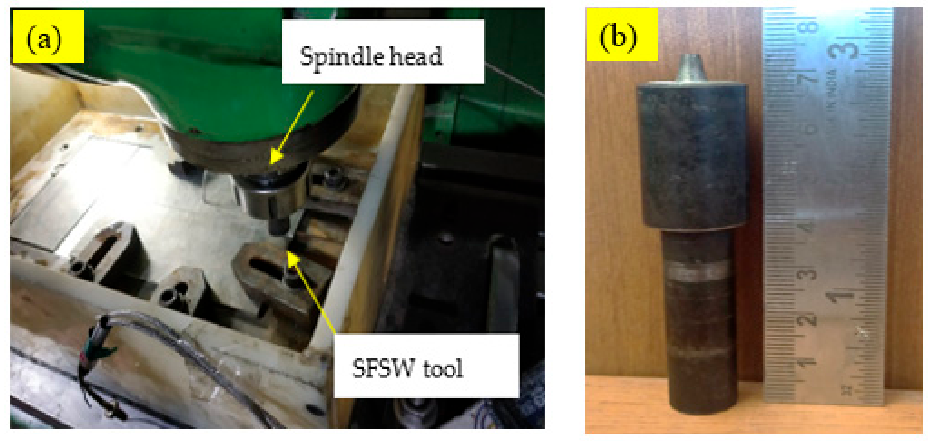
Figure 1. (a) Experimental setup used for SFSW; (b) Conical tool used in experiments.
Metals 13 01159 g001
Figure 2. Surface morphologies of the welded joints: (a) IA, (b) WR, (c) WC, (d) WH.
Metals 13 01159 g002
Figure 3. Weld macroscopic images of a friction-stir-welded sample: (a) IA, (b) WR, (c) WC, (d) WH.
Metals 13 01159 g003
Figure 4. EBSD orientation maps of SZ of welded samples: (a) IA, (b) WR, (c) WC, (d) WH.
Metals 13 01159 g004
Figure 5. Microhardness profile of the welded joint.
Metals 13 01159 g005
Figure 6. Stress-strain curves for the IA, WR, WC, and WH joints.
Metals 13 01159 g006
Figure 7. Ultimate tensile strength and % elongation of welded joints.
Metals 13 01159 g007
Figure 8. SEM morphologies of tensile fracture surfaces of (a) IA, (b) WR, (c) WC, (d) WH.
Metals 13 01159 g008
Table 1. Chemical composition and mechanical properties of Al 6061-T6.
Chemical CompositionMechanical PROPERTIES
ElementsMgSiMnZnFeCuAlUTS (MPa)YS (MPa)% Elongation
Alloying elements (%)1.140.670.120.250.350.30Rest30727520
Disclaimer/Publisher’s Note: The statements, opinions and data contained in all publications are solely those of the individual author(s) and contributor(s) and not of MDPI and/or the editor(s). MDPI and/or the editor(s) disclaim responsibility for any injury to people or property resulting from any ideas, methods, instructions or products referred to in the content.