Article

Effects of Micro-Arc Oxidation Surface Treatment on the Corrosion Resistance of Ti-6Al-4V Electron-Beam-Welded Joints

1
Institute of Process Equipment and Control Engineering, Zhejiang University of Technology, Hangzhou 310023, China
2
Engineering Research Center of Process Equipment and Remanufacturing, Ministry of Education, Zhejiang University of Technology, Hangzhou 310023, China
3
Department of Physics, Department of Materials Science and Engineering, and Department of Biomedical Engineering, City University of Hong Kong, Tat Chee Avenue, Kowloon, Hong Kong 999077, China
4
Department of Materials and Chemical Engineering, Heilongjiang Institute of Technology, Harbin 150050, China
5
Wenzhou Special Equipment Inspection & Science Research Institute, Wenzhou 325800, China
*
Authors to whom correspondence should be addressed.
Metals 2023, 13(7), 1161; https://doi.org/10.3390/met13071161
Submission received: 11 May 2023 / Revised: 18 June 2023 / Accepted: 20 June 2023 / Published: 22 June 2023
(This article belongs to the Special Issue Microstructure Evolution in Welded Joints)

Abstract

:
Micro-arc oxidation (MAO) is performed on Ti-6Al-4V electron-beam-welded joints, and the microstructure, phase composition, and corrosion resistance of the joint and surface coating are investigated systematically by scanning electron microscopy (SEM), energy-dispersive X-ray spectroscopy (EDS), X-ray diffraction (XRD), as well as electrochemical and stress corrosion analyses. SEM analyses revealed that the joint undergoes a phase transformation. The coating morphology of the joint and base materials is similar, but the joint coating is denser and thicker. XRD analyses recognize the rutile and anatase phases in the coating. Polarization and electrochemical impedance spectroscopy (EIS) corrosion tests reveal that the MAO treatment results in a decrease of two orders of magnitude in the corrosion current density of the welded joint and an increment of corrosion resistance. Stress corrosion evaluation reveals that a dense layer is exposed to protect the joint after long-term exposure to a high-stress corrosion environment. No stress corrosion-induced cracking or defects are observed in the joints, indicating the corrosion resistance of the joint has significantly improved.

1. Introduction

Titanium and its alloys possess many excellent properties, such as low density, high specific strength, and corrosion resistance [1,2,3]. With the development of ocean equipment and high-performance ships, there is an increasing demand for many marine applications. Electron beam welding (EBW), which possesses many advantages such as high energy density and welding speed, large fusion depth, a small heat-affected zone, and good protection effects, is a desirable choice for precision welding of titanium alloys or other active and difficult-to-dissolve metals [4,5]. However, the microstructure between the joint and the base metal is inconsistent. For example, the microstructure of the Ti-6Al-4V base metal is mainly composed of the primary α phase and intergranular β phase, but the heat-treated microstructure chiefly consists of the primary α phase, residual β phase, and precipitated acicular martensite-α’. The typical microstructure of the weld bead consists of coarse columnar β grains and the α’ phase caused by non-equilibrium solidification due to rapid melting and high cooling rates in the fusion zone [1,2]. The heterogeneity of the microstructure is the main factor leading to corrosion. For example, the α’ phase in the β phase accelerates the corrosion of titanium alloys [6]. In addition, pitting mainly occurs on the α’ grains to form the stressed surface, and the combined action of stress and impurity oxidation induces stress corrosion and the formation of a porous passive layer in the joint [7]. Although titanium alloys form passivation films during service in the marine environment, the films can rupture under high hydrostatic pressure, resulting in stress corrosion [8].
Post-weld heat treatment is an effective method to improve the corrosion resistance of joints. Reza et al. investigated the effect of post-weld heat treatment on the corrosion properties of the explosively bonded interface of A5083/AA1050/SS321 tubes [9]. The results show that by increasing the temperature and time of the heat treatment process, the energy stored due to explosive welding is reduced, the difference in the concentration of aluminum related to steel in the interface layer decreases, and the corrosion rate (current density) and electrical charge transfer decrease. Adjusting process parameters is also helpful in improving the corrosion resistance of joints. Jandaghi et al. analyzed the microstructural evolutions and their impact on the corrosion behavior of explosively welded Al/Cu bimetal [10]. The results of polarization and electrochemical impedance spectroscopy (EIS) corrosion tests show that a lower stand-off distance resulted in a decrease in corrosion potential, current rate, and concentration gradient at the interface. Micro-arc oxidation (MAO) is widely used to prevent corrosion of valve metals such as Mg, Al, Ti, and their alloys [11,12]. Shokouhfar et al. studied the corrosion resistance of the ceramic coating on the Ti substrate by MAO in different electrolytes. They found that coated samples showed better corrosion behavior than bare titanium. Additionally, the spark voltage of oxide films has a significant effect on the surface morphology, size, and homogeneity of micro-pores, thickness, and corrosion properties of coatings [13]. Zhang et al. study the growth mechanism of titania on a titanium substrate during the early stage of plasma electrolytic oxidation. They find that the combined effect of porosity and thickness in the PEO coating is responsible for the improvement in corrosion resistance [14]. Lately, the study of micro-arc oxidation on Ti alloy has focused on its combination with high-energy beam technology. For example, Nisar et al. investigated the corrosion performance of plasma electrolytic oxidation coatings on femtosecond laser-treated Ti-6Al-4V alloy. They find that femtosecond coating with MAO provides enhanced mechanical and adhesion properties with an exceptional passivation effect to reduce the corrosion rate [15]. Wu et al. study the microstructural evolution and biological properties of MAO coating on selective laser melting (SLM)-prepared NiTi alloy. They find that the MAO process can effectively improve the corrosion resistance and biological activity of SLM-NiTi alloy and inhibit the release of Ni elements [16]. However, far too little attention has been paid to the corrosion behavior of electron beam welded Ti-6Al-4V alloy. After electron beam welding, the joint microstructures of the titanium alloys also change. However, the effects of these changes are not clear and understood, and in particular, the effects of MAO on the corrosion resistance of Ti-6Al-4V electron-beam-welded joints have not been extensively studied [17,18,19]. Hence, the main aim of this study is to explore the corrosion behavior and microstructure changes in Ti-6Al-4V joints produced by the electron beam welding technique. Herein, Na2SiO3 and Na3PO4 are used as the electrolytes to treat the Ti-6Al-4V electron-beam-welded joints and base metal by MAO. The effects of the MAO treatment on the microstructure and stress corrosion of the welded joints are investigated, and the mechanism for the improved corrosion resistance is explored and discussed.

2. Experimental Details

2.1. Preparation of Electron-Beam-Welded Ti-6Al-4V Joints

Table 1 shows the chemical composition of the Ti-6Al-4V alloy. Its tensile strength, yield strength, and elastic modulus are 942 MPa, 845 MPa, and 108 GPa. The Ti-6Al-4V alloy joints (50 mm × 50 mm × 2 mm and 50 mm × 25 mm × 2 mm) were prepared using the THDW-4 electron beam welder. Its accelerating voltage is 0~70 kV, the electron beam current is 0~50 mA, the beam power is 3 kW, and the ultimate vacuum degree of the welding chamber is 10−2 Pa. Before welding, the samples were polished with SiC sandpaper (320#–1000#) to remove the surface oxide film, cleaned ultrasonically in acetone to remove oil stains, underwent passivation (HF: HNO3: H2O = 5:15:80), and cleaned with ethanol for later use. During welding, the voltage was 65 kV, the welding current was 10 mA, and the welding speed was 300 mm·min−1. The joints showed an overall silver-white color, and the patterns were continuous and uniform with no obvious defects such as cracks, depressions, or undercutting. Figure 1 depicts the schematic drawing of electron beam welding and the subsequent MAO process.

2.2. Preparation of MAO Coatings

A pulsed bipolar power supply was employed to perform the MAO process. Its power is 30 kVA, the output voltage is 0~750 V, the output current is 0~50 A, the duty cycle is 5~95%, and the frequency is 20~2000 Hz. Before the MAO process, the samples were cleaned ultrasonically in a mixture of acetone and alcohol. The electrolytes were: 15 g/L Na2SiO3, 10 g/L Na3PO4, and 1 g/L NaOH. The samples were the anode, and the stainless steel tank was the cathode (Figure 1). The other instrumental parameters were: current density = 12 A/dm2, duty cycle = 20%, pulsing frequency = 300 Hz, and processing time = 20 min. After the treatment, the residual electrolytes on the samples were removed by rinsing with deionized water for 3 min and then sonicating in alcohol for 5 min. The samples were dried with a blower and stored in a bag for later use.

2.3. Characterization

The surface and cross-sectional microstructures of the gold-coated Ti-6Al-4V electron-beam-welded joints before and after MAO were examined by field-emission scanning electron microscopy (SEM, Gemini 500, 15 kV) equipped with the Bruker D8 Advance energy dispersive spectroscopy (EDS) to determine the elemental composition. The phase compositions of the joints and coatings were analyzed by X-ray diffraction using a voltage of 40 kV, a current of 50 mA, a wavelength of 0.1541 nm, and a 2θ range of 10°–90°. The images were processed by the ImageJ software to analyze the pore size and distribution as well as the porosity of the coating.

2.4. Electrochemical Assessment

Potentiodynamic measurements and electrochemical impedance spectroscopy (EIS) were applied to study the corrosion performance of the samples. All the electrochemical tests were performed with the aim of the CorrTest CS350H electrochemical workstation at room temperature. The samples and copper wires are connected with tin solder. The sample was sealed by a cold-embedding method to expose an area of 1 cm2. The electrochemical test was conducted on the three-electrode cell system in an aqueous 3.5 wt% NaCl solution. The sample was the working electrode (WE), the platinum electrode was the auxiliary electrode (CE), and the saturated calomel electrode (RE) was the reference electrode. A potentiodynamic polarization test was conducted at a scanning rate of 10 mV·s−1 and a scanning range of −1~2 V (vs. OCP). An electrochemical impedance spectroscopy (EIS) test was conducted in a frequency range of 100 kHz to at 10−1 Hz and 10 mV around the OCP. Meanwhile, the required time to reach the steady state was 2 h.

2.5. Stress Corrosion Evaluation

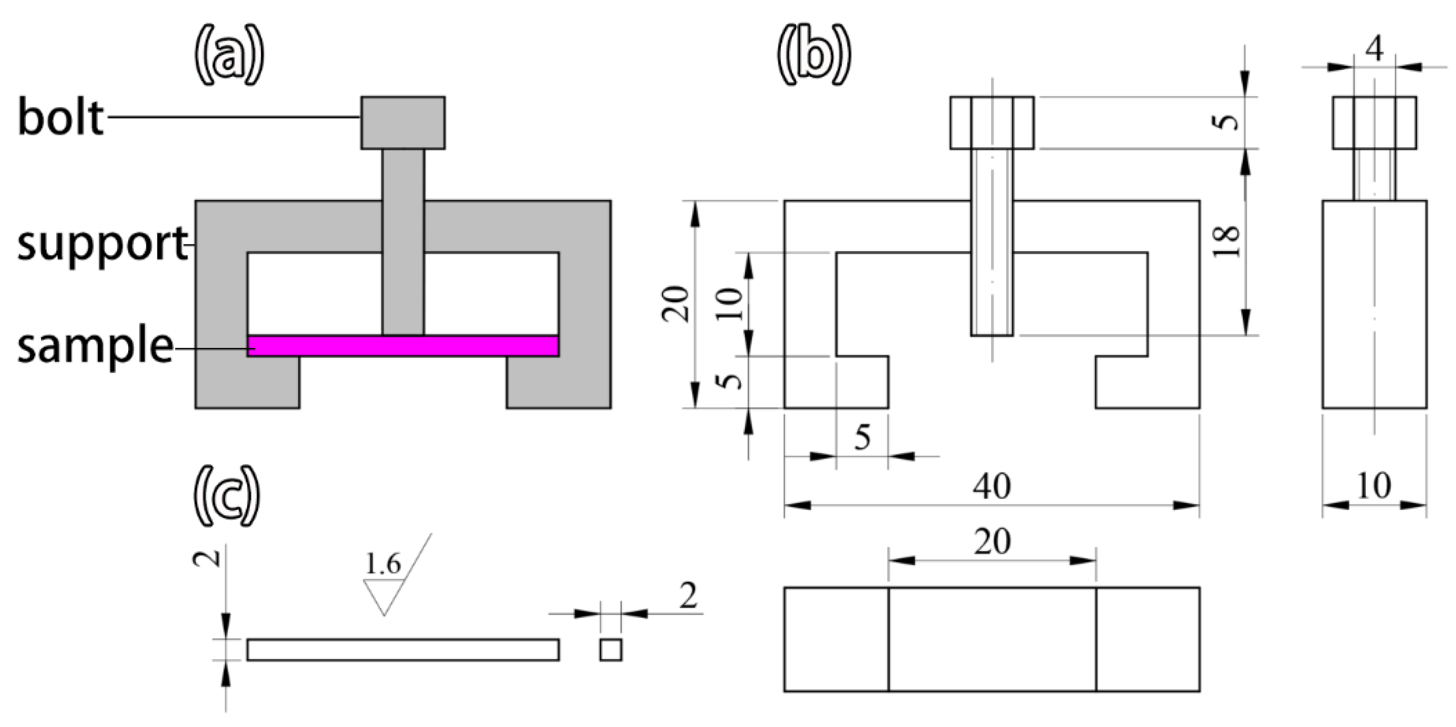
Stress corrosion evaluation was performed according to ASMT G39-99. The experimental setup depicted in Figure 2a,b consisted of two parts: bolts and brackets. The solution was 2.9 M NaCl + 0.1 M HCl with constant displacement at room temperature, and the dimensions of the specimens were 30 mm × 2 mm × 2 mm. The stress was controlled by applying a deflection with the bolt. The stress was 800 MPa, and the test duration was 30 days. Table 2 shows the sample coding based on Figure 1, electron beam welding (EBW), and the MAO process.

3. Results and Discussion

3.1. Ti-6Al-4V Joint Morphology

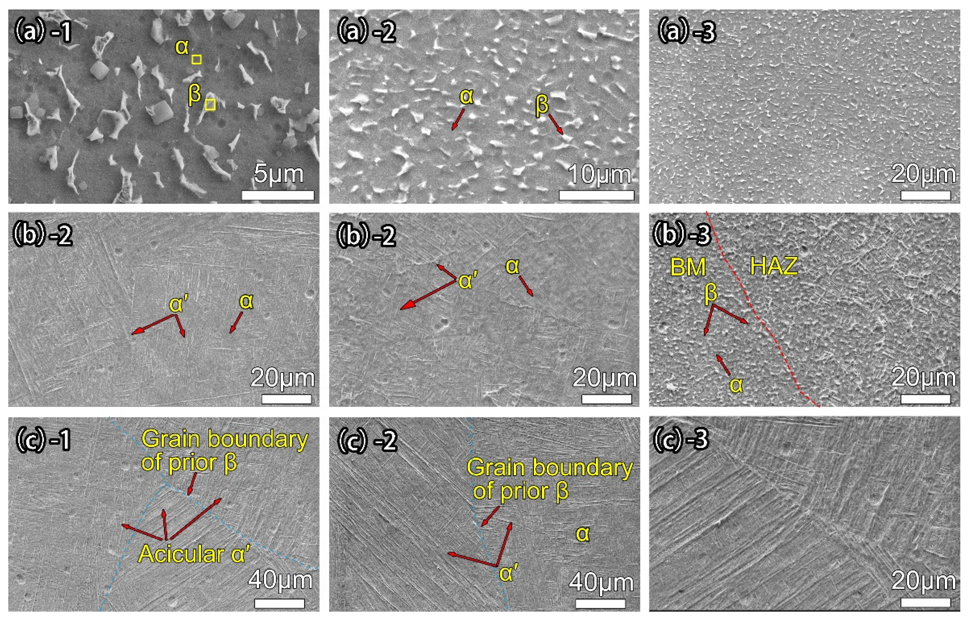
Figure 3 shows the microstructures of different regions of the Ti-6Al-4V electron-beam-welded joint. The microstructure of S0 is composed chiefly of the primary α phase (dark color) and intergranular β phase (bright color), while S1 consists of mainly the primary α phase, residual β phase, and fine acicular α’ martensite [2]. Owing to the high temperature and relatively low cooling rate in the welded zone (WZ), the high-temperature β phase transforms into the acicular α’ martensite, and α’ martensite clusters with the same orientation, and some acicular α’ martensite precipitates are formed from the β grain boundary. The former is distributed in a feather-like pattern on both sides of the grain boundary, while the latter is distributed in a disorderly manner with some vertical growth and formation of the grain boundary (GB) α [20]. The reason for the α phase preservation may be the absorption of oxygen by titanium, which is an α-stabilizer.

3.2. Coating Morphology and Structure

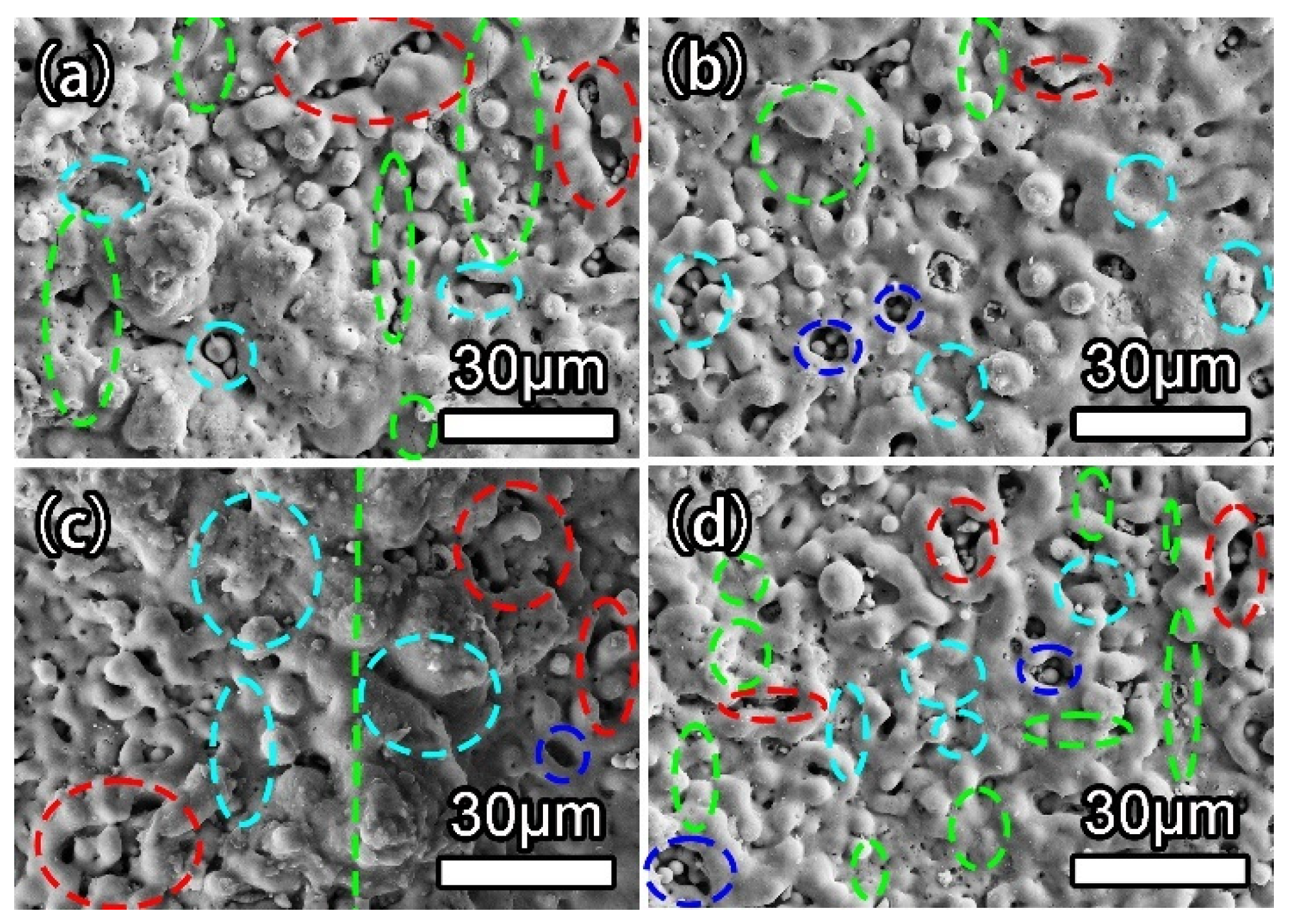
Figure 4a–d show the microscopic morphology of the joint coating. The surface features are similar, showing unevenly distributed micro-pores of different sizes and molten protrusions resembling volcanoes. There are two main reasons for the formation of the morphology. Firstly, when the voltage exceeds the breakdown voltage, the anions in the electrolyte move toward the substrate and enter the discharge channel under the action of the electric field. The high voltage and high temperature lead to the preferential breakdown of the weak anodic oxide film on the substrate via a series of chemical reactions in the electrolyte to generate the molten oxide products. Subsequently, the oxide products are discharged from the discharge channel and deposited on the substrate surface to form micro-protrusions with micro-pores under the cooling effect of the electrolyte. On the other hand, the gas generated from the reaction can produce micro-pores [11]. As the thickness of the MAO coating increases, the energy required to break through the coating becomes greater. Hence, the reaction gradually becomes stronger. More multiple micropores are fused, and more molten materials are ejected, leaving long micropores (red circular area) and elliptical micropores (blue circular area). Micro-cracks are also formed on the surface of the coating (green circle area) due to the large stress caused by rapid cooling when the molten materials contact the electrolyte [21].
Figure 5 depicts the cross-sectional morphology of the different regions of the MAO coatings, and they are quite similar. The interface between the coating and substrate is uneven due to the melting of the layer and substrate caused by the high temperature and pressure during arc discharges. Consequently, the film and substrate form a strong metallurgical bond [22].
Generally, the coatings in each area are relatively dense, especially the joint coating. Although the power parameters are constant, the uneven microstructure in the different areas gives rise to different oxidation durations. Compared to other areas, the duration of the MAO process in the WZ region is longer. The coating with defects gradually breaks down and falls off, consequently improving the overall compactness of the coating. There is a separation between the loose and dense layers in the fusion zone and the melting and self-sealing holes near the fusion line (FL), as manifested by the large roughness and pore size shown in Figure 4c and Figure 5c. This may be due to the sharp corners in the areas [23], which lead to repeated breakdowns caused by the point discharge. More breakdowns occur to produce a larger surface pore size and roughness.
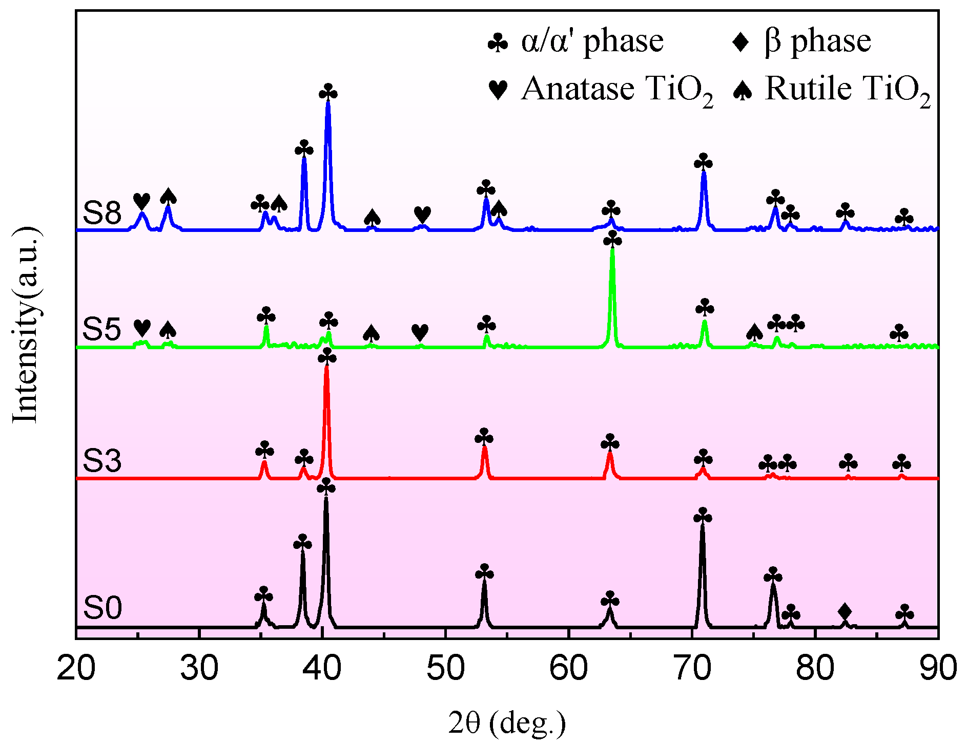
Figure 6 shows the analysis of the different regions before and after MAO. The XRD spectrum of the base metal (BM) shows diffraction peaks of both the α and β phases, indicative of the typical (α + β) bimodal microstructure in the BM with mostly the α phase. The WZ region comprises the α phase and acicular α’ martensite, which are difficult to distinguish because both phases have the hexagonal compact packed (HCP) structure with similar lattice parameters and appear at the same diffraction angle (2θ). Therefore, the peaks of the α phase and acicular α’ martensite are almost identical in the XRD pattern [24]. The phases of the MAO coatings in the BM and WZ regions are similar, mainly showing the rutile phase TiO2 and anatase phase TiO2. The reason for the appearance of α and α’ phases in the MAO coatings is due to the small coating thickness and surface micropores, thus allowing the X-ray to penetrate the coating [25]. Additionally, due to the formation of an oxide film, the beta phase disappeared (82°) [15].

3.3. Electrochemical Corrosion

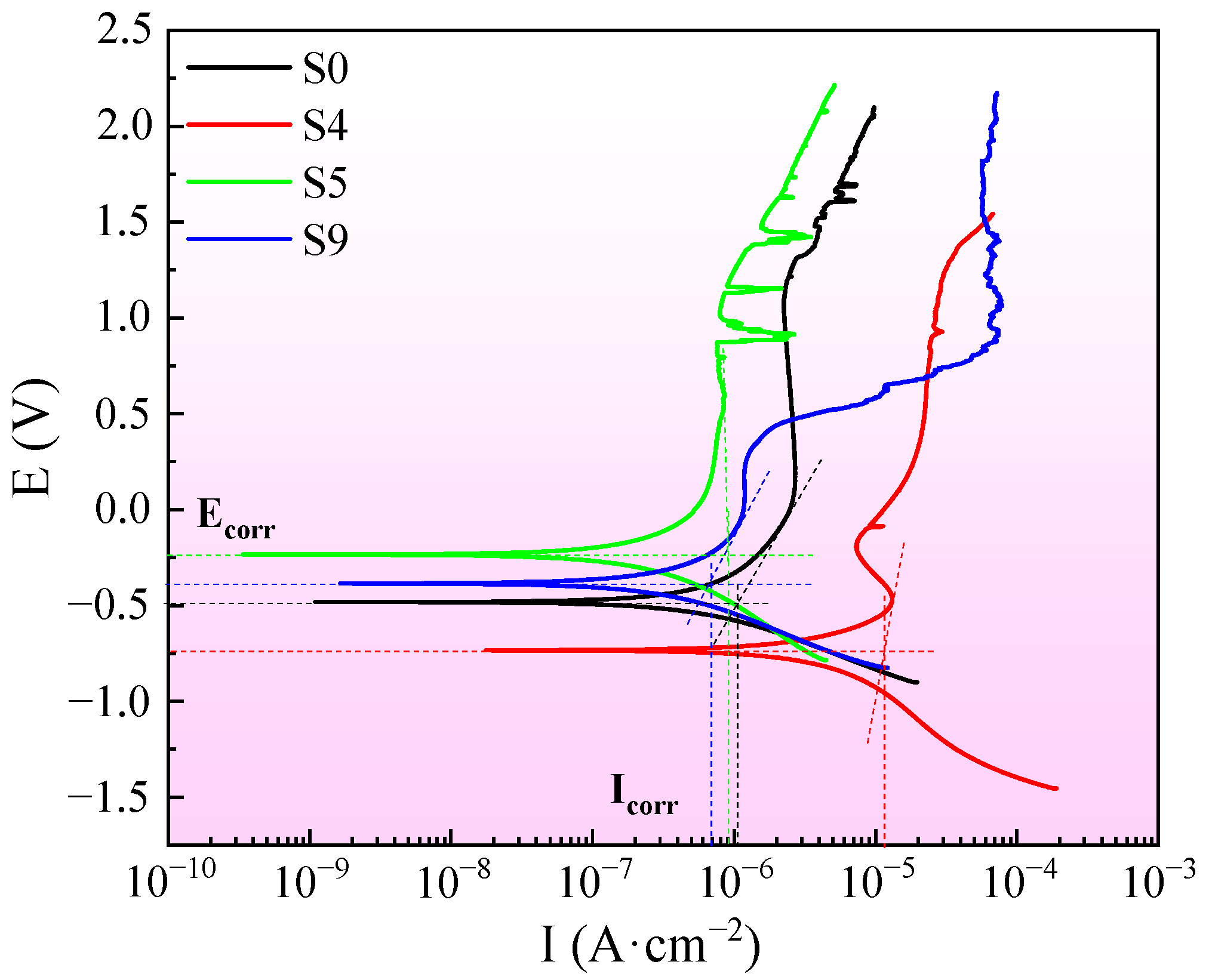
Figure 7 presents the dynamic polarization curves of the base metal and welded joint before and after MAO treatment. Electrochemical parameters, such as corrosion potential (Ecorr), corrosion current density (Icorr) (corrosion rate), and the gradients of anodic and cathodic Tafel obtained, have been extracted from these curves and reported in Table 3. Icorr is calculated by selecting the Tafel zone to fit the polarization curve. The Icorr values of the welding joint (WJ) increase by an order of magnitude, whereas Ecorr decreases significantly, suggesting significantly better corrosion resistance. The reason is that it is difficult for α’ martensite to form the passivation film, and the metal atoms at the grain boundaries are found in [26]. Furthermore, the WJ and BM regions form galvanic cells due to their potential differences to accelerate corrosion behavior [27]. After the MAO treatment, the self-corrosion potentials of the BM and WJ coatings increase significantly, but the self-corrosion current densities decrease by two orders of magnitude. Obvious passivation is observed in the WJ coating, indicating that MAO improves the corrosion resistance of the joint.
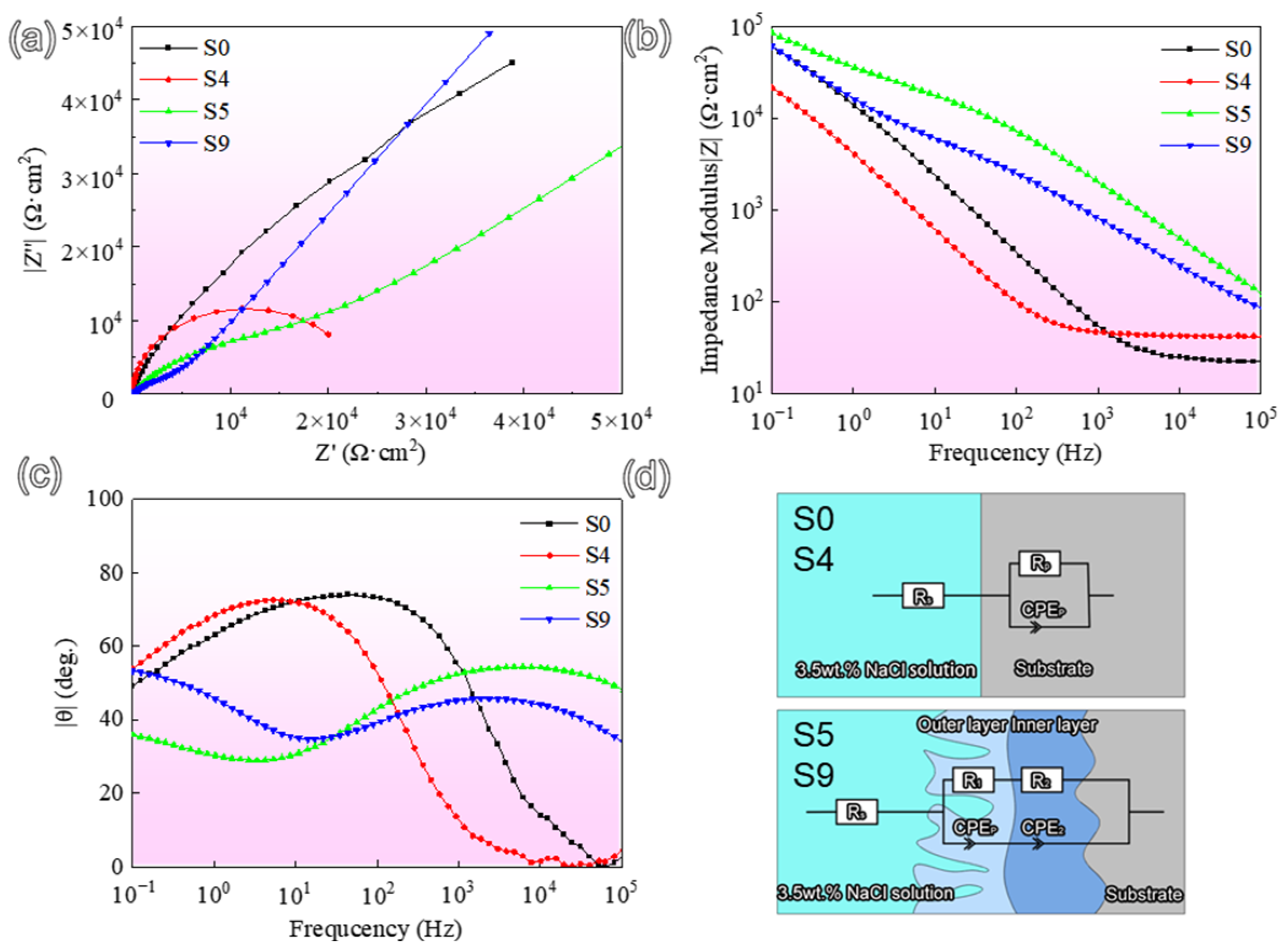
Figure 8a–c shows the Nyquist diagrams and Bode plots of the base metal and welded joint before and after MAO treatment. EIS data are obtained using the equivalent circuit presented in Figure 8d, which is in good accordance with experimental results and represented in Table 4.
The coated samples (S5 and S9) possess obvious capacitive arcs with a much larger radius than S0 and S4. As shown in Figure 8b, S4 displays the lowest modulus of impedance (|Z|) at a low frequency of around 10−1 Hz, indicating the poor protective performance of the oxide layer. In contrast, both of the coated samples present higher values of |Z|, especially for the joint coating (S9), which is almost one order of magnitude higher than S4. Moreover, the coating integrity is evaluated by the phase angles (−θ) at higher frequencies, which are well associated with enhanced anti-corrosion performance. Evidently, a larger phase angle is observed in the high-frequency range for the joint coating (S9), indicating that the deposited ceramic coating can effectively seal the defects and further increase the surface compactness. Equivalent circuits were applied to fit the raw EIS data, and the fitting results are listed in Table 4. In the equivalent circuits, Rs is the resistance associated with the electrolyte solution; resistance Rp and capacitance CPEp corresponds to the oxide layer, R1, and CPE1 refer to the outer porous layer; and R2 and CPE2 represent the inner compact layer, respectively. As shown in Table 1, the uncoated joint presents the lowest polarization resistance (Rp, approximately 4.563 × 10⁴ Ω·cm2). It should be noted that the corrosion resistance of the coated substrates is primarily dominated by the performance of the inner compact layer. A higher R2 value (1.39 × 10¹³ Ω·cm2) associates to better anticorrosion performance.

3.4. Stress Corrosion

Figure 9 shows pictures of the compressed S4 and S9 after soaking in the acidic NaCl solution for 30 days. The color of S4 is dull, and no obvious cracks are observed, as shown by the red dashed circle in Figure 9a. Figure 9b shows partial detachment of the coating.
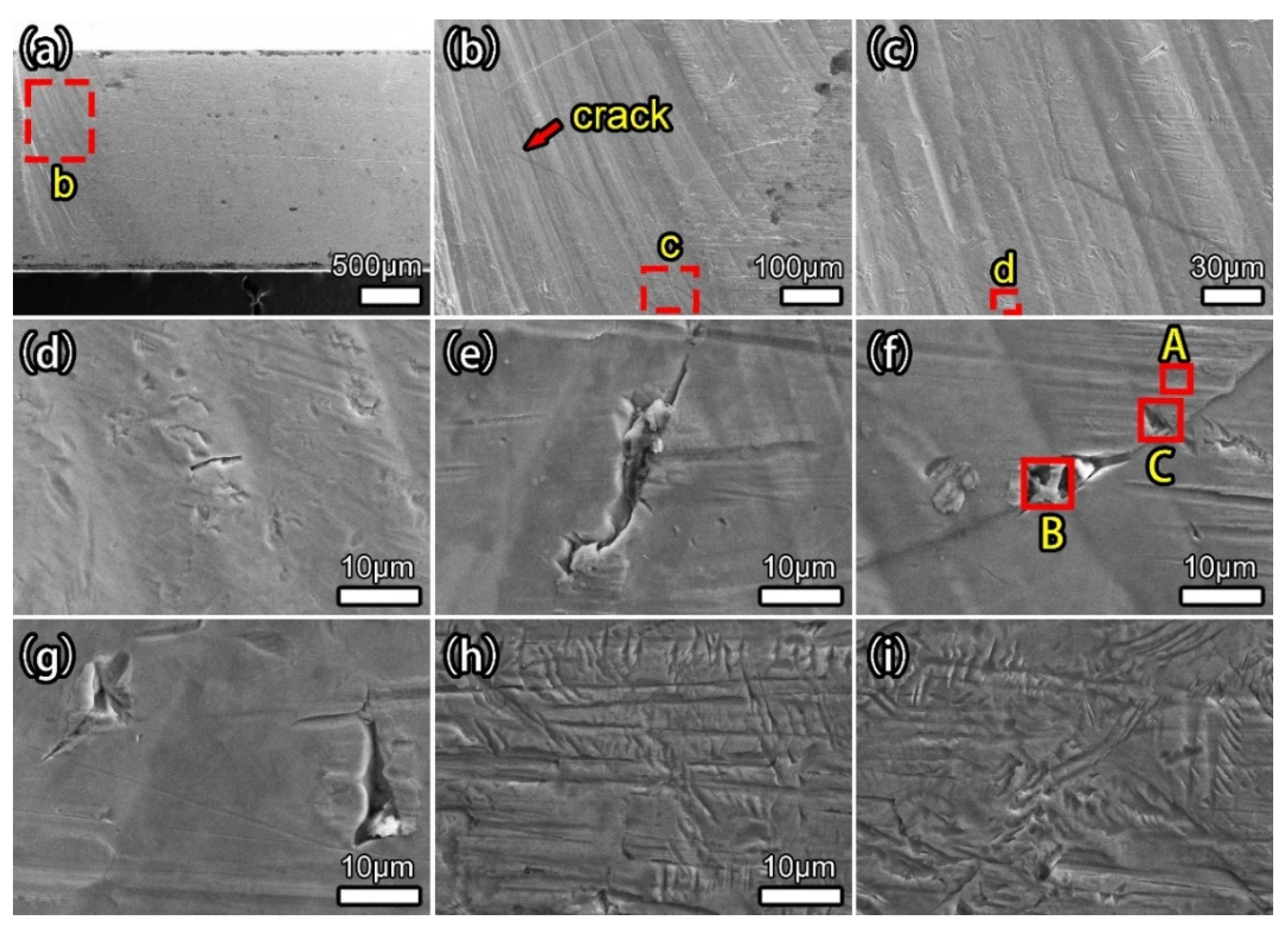
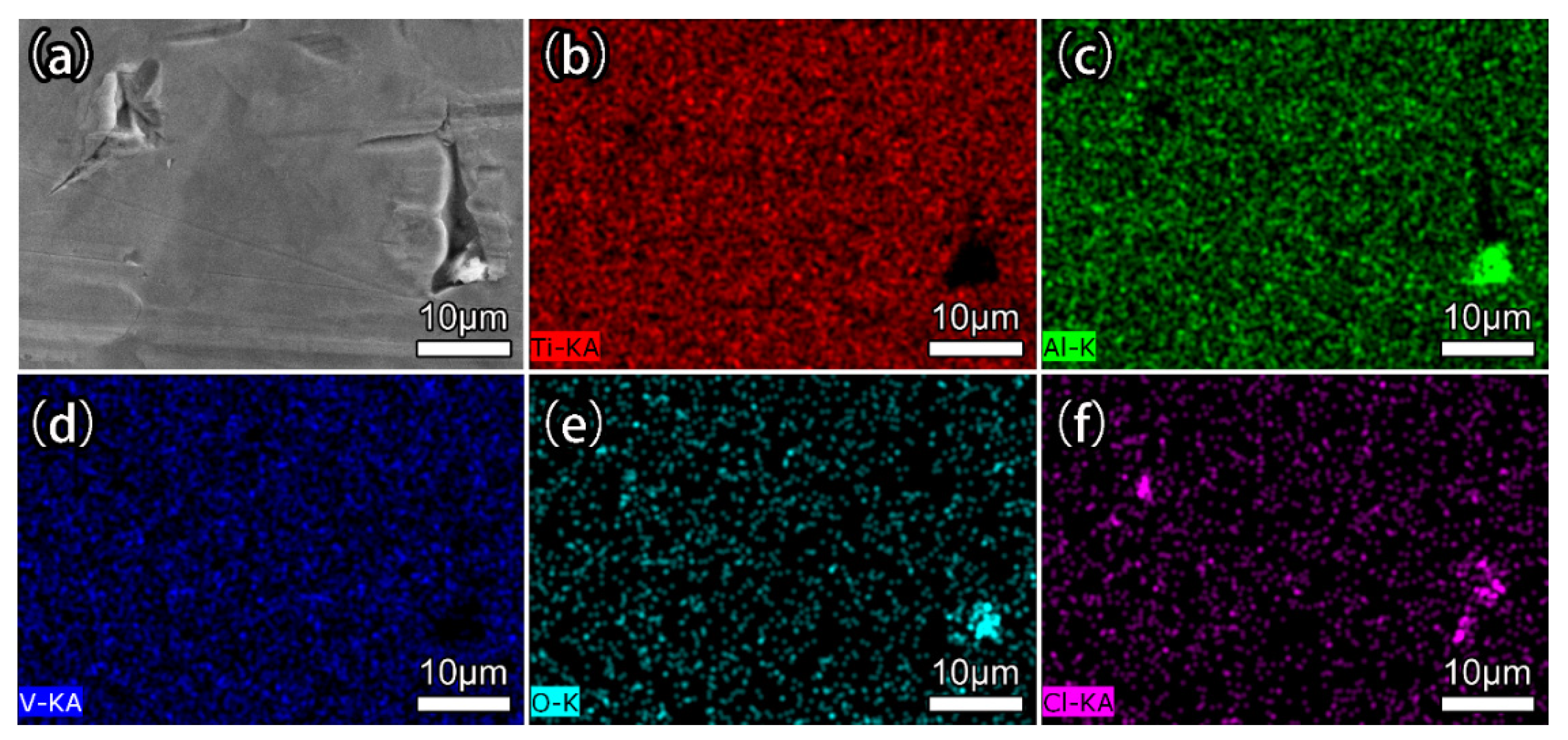
Figure 10 shows the stress-corroded morphology of the welded joint. There are many microcracks. The large grooves in Figure 10h,I may arise from corrosion of the α’ martensite bundles. In the acidic NaCl solution, Cl and H+ cause dissolution and rupture of the passivation film to produce pitting, and the high stress promotes the spreading of the pitting to both sides, transforming into microcracks. Additionally, dissolution and hydrolysis result in acidification at the crack tip and produce a lower pH value at the tip. H+ is precipitated and absorbed by the cracked tip to form hydrogen [28,29]. The combined effects of tensile stress and hydrogen pressure formed around the crack tip promote crack propagation. Figure 11 shows the elements around the crack, and a large amount of Cl and alumina is observed to accumulate in the microcrack area. The existence of alumina is due to the oxidation reaction of solid solution elements. Table 5 shows the relationship between the chlorine content and cracks in Figure 10f, and as the crack size increases, the amount of Cl increases.
Figure 12 shows the corrosion morphology of S8. Figure 12a–c show that the outer loose layer delaminates extensively to expose the inner dense layer, and extensive pitting is observed from the coating. The outer layer has many cracks, showing a pattern as shown in Figure 12c,d. The initiation of microcracks can be observed at B in Figure 12d. In addition, two cracks end at point C. The formation of cracks at point B should be due to the stress concentration caused by micropores [30]. The integrated effects of tensile stress and corrosive media result in microcracks. The connection between the crack and other cracks should be the main cause of coating detachment [31].
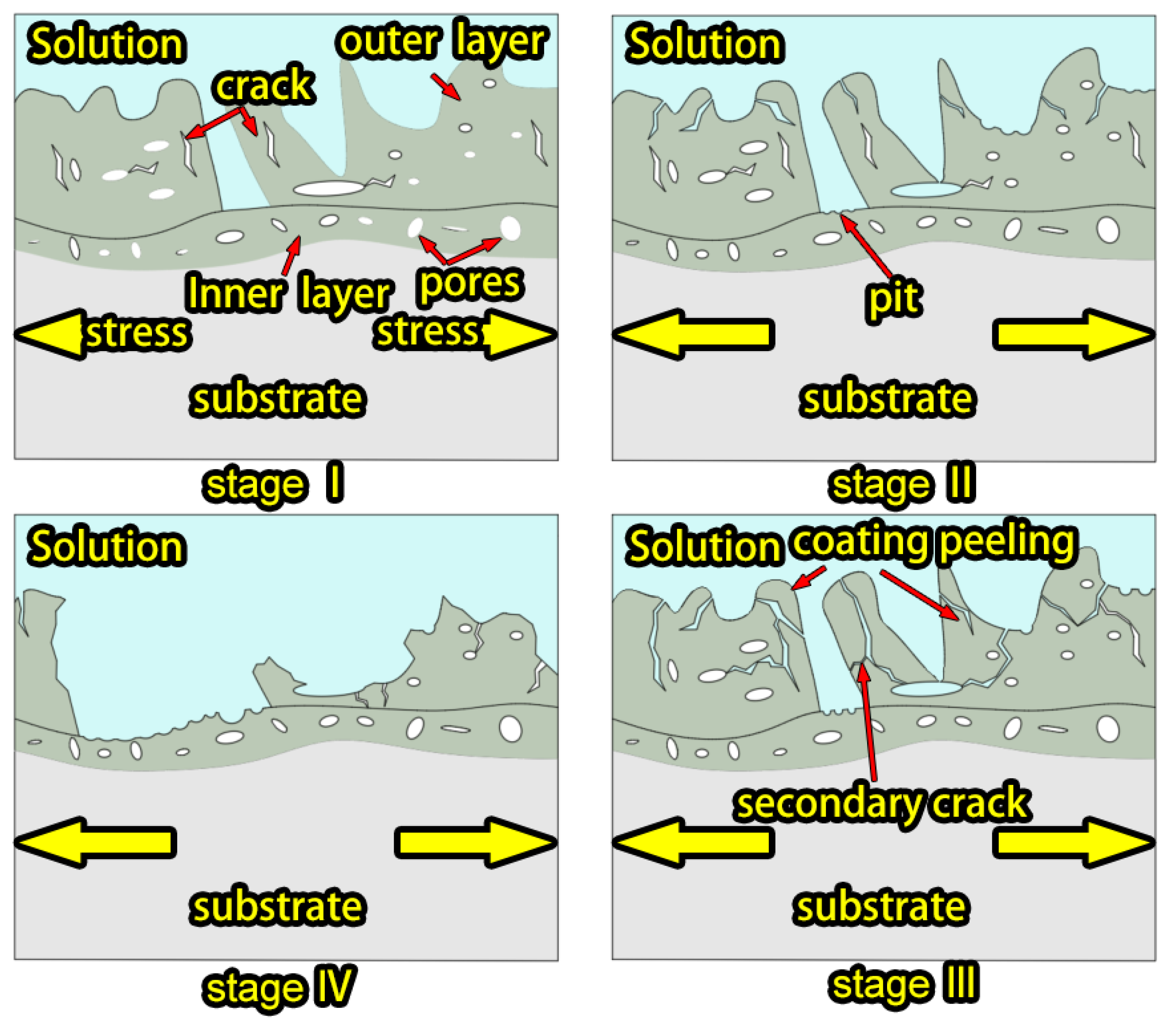
A schematic illustration of the corrosion mechanism rendered by the WZ coating is displayed in Figure 13. Stress corrosion takes place in four stages. In the first stage, when the stress exceeds the yield limit of the MAO coating, a small amount of microcracks begin to form, and pitting forms at the notch. In the second stage, pitting evolves gradually into microcracks, and Cl- and H+ enter the interior of the coating along the cracks. H+ absorbs at the crack tip to form hydride. The combined effects of the tensile stress and hydrogen pressure around the crack tip promote crack propagation. In the third stage, the microcracks proliferate, accompanied by the formation of secondary cracks. The cracks that expand into multiple holes are interconnected to form a network, resulting in coating delamination. Moreover, large amounts of Cl and H+ enter the original defects in the coating and corrode the coating to form large cavities. The stress leads to coating cracking and spalling. In the fourth stage, a large area of the loose layer peels off and the dense layer is exposed to protect the substrate; owing to fewer defects, only pitting occurs.

4. Conclusions

There are significant differences in the microstructures between the electron-beam-welded joint and the base materials. After micro-arc oxidation (MAO), the phases of the MAO coatings in the BM and WZ regions are similar, mainly showing the rutile phase TiO2 and anatase phase TiO2. The coating structures in different regions are also similar, and the thickness of the coatings is around 10 µm. However, the joint coating is relatively dense and thick. Owing to the formation of metastable needle-like α’ martensite with high corrosion sensitivity in the joint, the corrosion potential (−0.733 V) is small and the self-corrosion current (1.14 × 10⁻⁵ A·cm−2) is large. After MAO, the corrosion potential (−0.463 V) increases and the self-corrosion current (6.76 × 10⁻⁷ A·cm−2) decreases by two orders of magnitude, demonstrating the enhanced electrochemical corrosion performance. Stress corrosion produces large cracks in the untreated joint, but after MAO, the loose layer of the coating delaminates under the combined action of stress and corrosion, consequently exposing the dense layer for better corrosion protection.

Author Contributions

Conceptualization, methodology, investigation, project administration, writing—original draft, funding acquisition, Y.M.; resources, investigation, data curation, P.W.; resources, data curation, J.M.; resources, data curation, Z.Y.; review and editing, supervision, funding acquisition, J.Y.; review and editing, Y.H.; review and editing, H.L.; review and editing, C.L.; review and editing, S.R.; writing—review and editing, funding acquisition, J.X.; writing—review and editing, Z.C.; review and editing, supervision, funding acquisition, P.K.C. All authors have read and agreed to the published version of the manuscript.

Funding

The work was supported by the National Natural Science Foundation of China (No. 51975530), the Department of Education of Zhejiang Province (No. Y202249101), the Heilongjiang Natural Science Foundation (No. LH2022E102), the City University of Hong Kong Strategic Research Grant (SRG No. 7005505), and the City University of Hong Kong Donation Research Grant (No. DON-RMG 9229021).

Data Availability Statement

The data that support the findings of this study are available from the corresponding author upon reasonable request.

Conflicts of Interest

The authors declare no conflict of interest.

References

  1. Chen, G.Q.; Zhang, G.; Yin, Q.X.; Zhang, B.G.; Feng, J.C. Microstructure evolution of electron beam welded joints of Ti-43Al-9V-0.3Y and Ti-6Al-4V alloys. Mater. Lett. 2018, 233, 336–339. [Google Scholar] [CrossRef]
  2. Li, J.N.; Li, J.S.; Qi, W.J.; Liu, K.G. Characterization and mechanical properties of thick TC4 titanium alloy sheets welded joint by vacuum EBW. Vacuum 2019, 168, 108812. [Google Scholar] [CrossRef]
  3. Su, M.L.; Li, J.N.; Liu, K.G.; Qi, W.J.; Weng, F.; Zhang, Y.B.; Li, J.S. Mechanical property and characterization of TA1 titanium alloy sheets welded by vacuum electron beam welding. Vacuum 2019, 159, 315–318. [Google Scholar] [CrossRef]
  4. Guo, S.; Zhou, Q.; Kong, J.; Peng, Y.; Xiang, Y.; Luo, T.Y.; Wang, K.H.; Zhu, J. Effect of beam offset on the characteristics of copper/304stainless steel electron beam welding. Vacuum 2016, 128, 205–212. [Google Scholar] [CrossRef]
  5. Sandhya, V.; Naga Phani Sastry, M.; Hemachandra Reddy, K. Influence of Welding Speed, Voltage, and Beam current on the microstructure and mechanical properties of Electron Beam-Welded Titanium radial joints. Mater. Today Proc. 2022, 64, 442–447. [Google Scholar] [CrossRef]
  6. Tamilselvi, S.; Nishimura, T.; Min, X.H.; Tsuzaki, M. The Effect of Microstructure on Corrosion of Molybdenum-Bearing Titanium Alloys in High Chloride and Acidic Solution at High Temperature. Mater. Trans. 2009, 50, 2545–2551. [Google Scholar] [CrossRef] [Green Version]
  7. Shamir, M.; Junaid, M.; Khan, F.N.; Taimoor, A.A.; Baig, M.N. A comparative study of electrochemical corrosion behavior in Laser and TIG welded Ti–5Al–2.5Sn alloy. J. Mater. Res. Technol. 2019, 8, 87–98. [Google Scholar] [CrossRef]
  8. Liu, R.; Cui, Y.; Liu, L.; Zhang, B.; Wang, F.H. A primary study of the effect of hydrostatic pressure on stress corrosion cracking of Ti-6Al-4V alloy in 3.5% NaCl solution. Corros. Sci. 2020, 165, 108402. [Google Scholar] [CrossRef]
  9. Jandaghi, M.R.; Abdollah Saboori, M.R.; Khalaj, G.; Ghareh Shiran, M.K. Microstructural Evolutions and its Impact on the Corrosion Behavior of Explosively Welded Al/Cu Bimetal. Metals 2020, 10, 634. [Google Scholar] [CrossRef]
  10. Shargh, S.F.; Saadat, A.; Najafi, A.; Gharehshiran, M.R.K.; Khalaj, G. Investigating the effect of post weld heat treatment on corrosion properties of explosive bonded interface of AA5083/AA1050/SS 321 tubes. Mater. Res. Express 2020, 7, 036529. [Google Scholar] [CrossRef]
  11. Fernández-López, P.; Alves, S.A.; Azpitarte, I.; San-José, J.T.; Bayón, R. Corrosion and tribocorrosion protection of novel PEO coatings on a secondary cast Al-Si alloy: Influence of polishing and sol-gel sealing. Corros. Sci. 2022, 207, 110548. [Google Scholar] [CrossRef]
  12. Quintero, D.; Galvis, O.; Calderón, J.A.; Gómez, M.A.; Castaño, J.G.; Echeverría, F.; Habazaki, H. Control of the physical properties of anodic coatings obtained by plasma electrolytic oxidation on Ti6Al4V alloy. Surf. Coat. Technol. 2015, 283, 210–222. [Google Scholar] [CrossRef]
  13. Shokouhfar, M.; Dehghanian, C.; Montazeri, M.; Baradaran, A. Preparation of ceramic coating on Ti substrate by plasma electrolytic oxidation in different electrolytes and evaluation of its corrosion resistance: Part II. Appl. Surf. Sci. 2012, 258, 2416–2423. [Google Scholar] [CrossRef]
  14. Zhang, X.X.; Cai, G.Y.; Lv, Y.; Wu, Y.L.; Dong, Z.H. Growth mechanism of titania on titanium substrate during the early stage of plasma electrolytic oxidation. Surf. Coat. Technol. 2020, 400, 126202. [Google Scholar] [CrossRef]
  15. Nisar, S.S.; Arun, S.; Choe, H.C. Plasma electrolytic oxidation coatings on femtosecond laser-treated Ti-6Al-4V alloy for bio-implant use. Surf. Coat. Technol. 2023, 464, 129553. [Google Scholar] [CrossRef]
  16. Wu, G.L.; Li, L.; Sun, M.; Wang, Y.; Luo, F.; Zhang, Q.L.; Liu, R.; Chen, Z.J.; Yao, J.H. Microstructural evolution and biological properties of PEO coating on SLM-prepared NiTi alloy. Surf. Coat. Technol. 2023, 452, 129065. [Google Scholar] [CrossRef]
  17. Liu, J.A.; Li, S.H.; Han, Z.W.; Cao, R.Z. Improved corrosion resistance of friction stir welded magnesium alloy with micro-arc oxidation/electroless plating duplex coating. Mater. Chem. Phys. 2021, 257, 123753. [Google Scholar] [CrossRef]
  18. Yang, Y.; Zhou, L.L. Improving Corrosion Resistance of Friction Stir Welding Joint of 7075 Aluminum Alloy by Micro-arc Oxidation. J. Mater. Sci. Technol. 2014, 30, 1251–1254. [Google Scholar] [CrossRef]
  19. Kamal Jayaraj, R.; Sree Sabari, S.; Prasanna Teja, K. Enhancing the corrosion resistance of stir zone of friction stir welded AZ31b magnesium alloy using micro arc oxidation coatings. Mater. Today Proc. 2019, 15, 68–75. [Google Scholar] [CrossRef]
  20. Sun, W.J.; Wang, S.L.; Wu, M.; Hong, M.; Chen, Y.H.; Xin, J.J.; Zhang, P.; Qin, Y.B.; Fang, N.W. Revealing tensile behaviors and fracture mechanism of Ti–6Al–4V titanium alloy electron-beam-welded joints using microstructure evolution and in situ tension observation. Mater. Sci. Eng. A 2021, 824, 141811. [Google Scholar] [CrossRef]
  21. Yang, X.; Wang, W.L.; Ma, W.J.; Wang, Y.; Yang, J.G.; Liu, S.F.; Tang, H.P. Corrosion and wear properties of micro-arc oxidation treated Ti6Al4V alloy prepared by selective electron beam melting. Trans. Nonferrous Met. Soc. China 2020, 30, 2132–2142. [Google Scholar] [CrossRef]
  22. Cheng, Y.L.; Wu, X.Q.; Xue, Z.G.; Matykina, E.; Skeldon, P.; Thompson, G.E. Microstructure, corrosion and wear performance of plasma electrolytic oxidation coatings formed on Ti–6Al–4V alloy in silicate-hexametaphosphate electrolyte. Surf. Coat. Technol. 2013, 217, 129–139. [Google Scholar] [CrossRef]
  23. Sankara Narayanan, T.S.N.; Kim, J.; Park, H.W. High performance corrosion and wear resistant Ti-6Al-4V alloy by the hybrid treatment method. Appl. Surf. Sci. 2020, 504, 144388. [Google Scholar] [CrossRef]
  24. Zeng, C.Y.; Zhang, Y.P.; Hu, J.L.; Hou, B.; Wang, H.Y.; Dong, C.; Zhou, Y. The role of microstructure on corrosion fatigue behavior of thick-plate Ti–6Al–4V joint via vacuum electron beam welding. Vacuum 2020, 182, 109714. [Google Scholar] [CrossRef]
  25. Sun, Z.C.; Li, X.S.; Wu, H.L.; Yang, H. Morphology evolution and growth mechanism of the secondary Widmanstatten α phase in the TA15 Ti-alloy. Mater. Charact. 2016, 118, 167–174. [Google Scholar] [CrossRef]
  26. Qin, T.; Lin, X.; Yu, J.; Wang, M.; Guo, P.F.; Li, J.Q.; Zhang, Y.F.; Liu, J.R.; Zhang, S.L.; Huang, W.D. Performance of different microstructure on electrochemical behaviors of laser solid formed Ti–6Al–4V alloy in NaCl solution. Corros. Sci. 2021, 185, 109392. [Google Scholar] [CrossRef]
  27. Seo, D.I.; Lee, J.B. Corrosion Characteristics of Additive-Manufactured Ti-6Al-4V Using Microdroplet Cell and Critical Pitting Temperature Techniques. J. Electrochem. Soc. 2019, 166, C428–C433. [Google Scholar] [CrossRef]
  28. Cao, S.; Zhu, S.M.; Samuel Lim, C.V.; Zhou, X.G.; Chen, X.B.; Hinton, B.R.W.; Boyer, R.R.; Williams, J.C.; Wu, X.H. The mechanism of aqueous stress-corrosion cracking of α + β titanium alloys. Corros. Sci. 2017, 125, 29–39. [Google Scholar] [CrossRef]
  29. Dong, Y.C.; Huang, S.; Wang, Y.Y.; Zhang, B.; Alexandrov, I.V.; Chang, H.; Dan, Z.H.; Ma, L.; Zhou, L. Stress corrosion cracking of TC4 ELI alloy with different microstructure in 3.5% NaCl solution. Mater. Charact. 2022, 194, 112357. [Google Scholar] [CrossRef]
  30. Ao, N.; Liu, D.X.; Zhang, X.H.; Liu, C.S. Enhanced fatigue performance of modified plasma electrolytic oxidation coated Ti-6Al-4V alloy: Effect of residual stress and gradient nanostructure. Appl. Surf. Sci. 2019, 489, 595–607. [Google Scholar] [CrossRef]
  31. Wang, S.Q.; Wang, Y.M.; Cao, G.; Chen, C.L.; Zhu, Y.X.; Serdechnova, M.; Blawert, C.; Zheludkevich, M.L.; Zou, Y.C.; Ouyang, J.H.; et al. High temperature oxidation and hot corrosion behaviors of PEO and PEO/polysilazane preceramic-based dual-layer coatings on Ti6Al4V alloy. Corros. Sci. 2023, 216, 111076. [Google Scholar] [CrossRef]
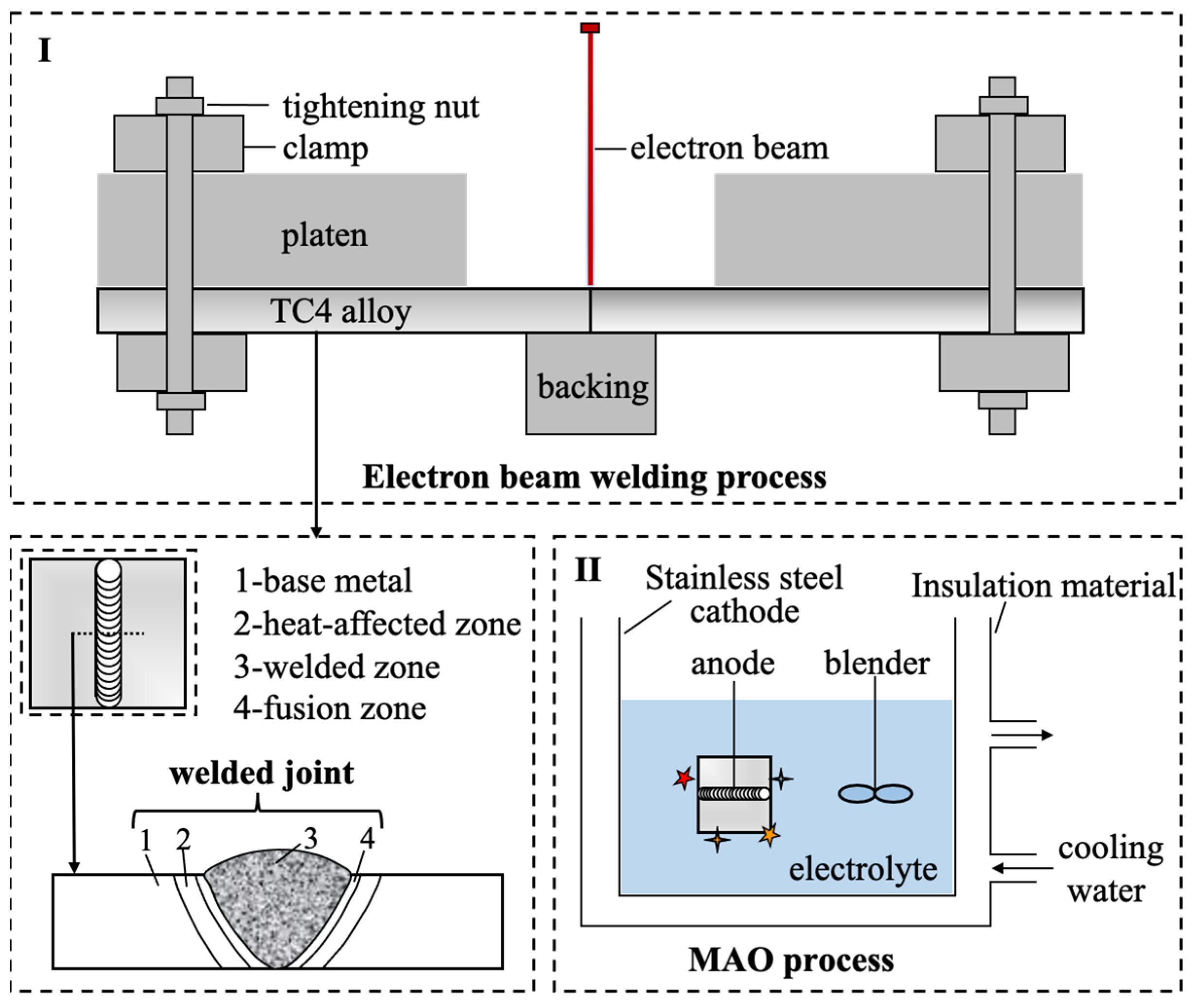
Figure 1. Schematic drawing of electron beam welding process (I) and subsequent MAO process (II).
Metals 13 01161 g001
Figure 2. (a) Schematic diagram; (b) Dimensions of the experimental setup; (c) Sample dimensions.
Metals 13 01161 g002
Figure 3. SEM images of (a-1, a-2, a-3) S0, (b-1, b-2, b-3) S1 and (c-1, c-2, c-3) S3 in different regions.
Metals 13 01161 g003
Figure 4. Surface morphologies of (a) S5, (b) S6, (c) S7, and (d) S8.
Metals 13 01161 g004
Figure 5. Cross-sectional morphologies of (a) S5, (b) S6, (c) S7, and (d) S8.
Metals 13 01161 g005
Figure 6. XRD patterns of S0, S3, S5, and S8.
Metals 13 01161 g006
Figure 7. Potentiodynamic polarization curves of S0, S4, S5, and S9 in the 3.5 wt.% NaCl solution.
Metals 13 01161 g007
Figure 8. EIS plot of S0, S4, S5, and S9 in a 3.5 wt.% NaCl solution: (a) Nyquist plot; (b) impedance modulus diagram; (c) phase diagram; (d) Equivalent circuit diagram.
Metals 13 01161 g008
Figure 9. Photographs of (a) S4 and (b) S9 immersed in the acidic NaCl solution for 30 days.
Metals 13 01161 g009
Figure 10. Stress corrosion morphologies of (ad) S3 and its partial enlargement, and (ei) Microcracks in S3.
Metals 13 01161 g010
Figure 11. EDS maps of S3 with cracks: (a) original image; (b) Ti element; (c) Al element; (d) V element; (e) O element; (f) Cl element.
Metals 13 01161 g011
Figure 12. Stress corrosion morphologies of (a) S8, (b) locally enlarged inner layer in S8, (c,d) locally enlarged residual outer layer in S3.
Metals 13 01161 g012
Figure 13. Schematic illustration of the corrosion mechanism of the WZ coating.
Metals 13 01161 g013
Table 1. The chemical composition of Ti-6Al-4V alloy (wt.%).
TiAlVFeOCNH
Ti-6Al-4VBal6.24.10.30.20.10.050.015
Table 2. Samples coding based on Figure 1; electron beam welding (EBW) and MAO treatment.
SampleSample DescriptionEBWMAO
S0 base metal (BM)NoNo
S1heat-affected zone (HAZ)YesNo
S2fusion zone (FZ)YesNo
S3welded zone (WZ)YesNo
S4welded joint (WJ)YesNo
S5BM treated by MAONoYes
S6HAZ treated by MAOYesYes
S7FZ treated by MAOYesYes
S8WZ treated by MAOYesYes
S9WJ treated by MAOYesYes
Table 3. Fitting results of potentiodynamic polarization curves of S0, S4, S5, and S9.
SamplesEcorr/VIcorr/A·cm−2βa/mV·dec−1βc/mV·dec−1
S0−0.4821.08 × 10−61227.5384.64
S4−0.7331.14 × 10−5812.691204.3
S5−0.2349.33 × 10−73278.4910.65
S9−0.4636.76 × 10−7864.44450.31
Table 4. Fitting results of EIS curves of S0, S4, S5, and S9.
ParameterS0S4S5S9
Rs (Ω · cm2)21.8542.5129.0231.81
CPEp/1−1sncm−2)1.45 × 10−55.09 × 10−51.63 × 10−68.17 × 10−6
np/10.830.850.650.57
Rp/1 (kΩ · cm2)100.3745.6319.138.49
CPE2−1sncm−2) 1.41 × 10−51.42 × 10−5
n2 0.450.66
R2 (MΩ · cm2) 1.95 × 1071.39 × 107
Table 5. Elemental concentrations of the three regions in Figure 10f (wt.%).
ElementsABC
Ti90.7475.6576.19
Al6.147.494.65
V1.872.290.89
O1.2512.9114.96
Disclaimer/Publisher’s Note: The statements, opinions and data contained in all publications are solely those of the individual author(s) and contributor(s) and not of MDPI and/or the editor(s). MDPI and/or the editor(s) disclaim responsibility for any injury to people or property resulting from any ideas, methods, instructions or products referred to in the content.