Abstract
The paper considers the possibility of reusing previously used railway rails. The analysis is conducted using the standards and operating conditions of the rails of one of the Central Asian states, Kazakhstan, as an example. The operation of these rails causes significant stresses, while the surface layers are strengthened as a result of cold hammering. These phenomena significantly change the physical and mechanical characteristics of rails. As a result, they may not be suitable in terms of parameters for basic use but can be suitable for installation on other tracks. The conducted studies have shown that when the standard service life of the RP65 rail expires, the surface layer is deformed to a depth of up to 300 microns, hardness increases, and internal residual stresses are formed. These changes lead to an increase in the strength properties of the rails. However, at the same time, cracks originate in the surface layer of the rail, thus worsening operational characteristics. The RP65 rails are used under a cyclic load of 700 kN (which is determined by the national standard), withstanding 790,000 cycles. When the load is reduced to 510 kN, these rails can withstand the 2,000,000 cycles required by the standard without failure. Thus, these rails can be reutilized only on non-loaded and non-critical sections.
1. Introduction
Rail transport plays a crucial role in the economies of the majority of countries, providing a significant share of all cargo turnovers and the transportation of most export and transit goods. This share in Central Asian countries may reach 50% or more. Railway rails perform an important function: the elastic transformation and transfer of loads proceeding from wheels to tracks, directing the running gears of locomotives and cars [1]. High requirements are imposed on the quality of rails during the operation of the railway track [2,3]. R65 rails are used in the manufacture of rail tracks in the most massive sections of traffic (main tracks) in Central Asia, such as the sections for cargo and passenger traffic. The speed of passenger trains in these sections reaches its maximum. In addition, freight trains are also involved in operations [4]. In such areas, steel with sufficiently good plastic properties and relatively low hardness (HB = 360–380 MPa) is used as the rail material. These rails are made of low-alloy carbon steel with a ferrite-pearlite structure [5]. There are many other sections in addition to the main railway, including industrial sections, safety dead ends, crossovers, turnouts, marshalling, engine tracks, and station tracks, that have completely different requirements for rails [6,7]. Of the listed types of tracks, industrial ones make up a considerable proportion of their total number (ranking second as compared to the main tracks). Rails of the RP65 type are used on these tracks. Their difference from R65 rails consists of the type of material used in their production. The chemical composition of the RP65 material differs by having a higher content of sulfur and phosphorus as compared to that of R65. Owing to this fact, R65 has a higher plasticity and a lower tendency to crack. The same low-alloy carbon steel with a ferrite-pearlite structure is used to produce RP65 rails. The proportion of doped components in such steel is slightly lower, and the number of sulfur and phosphorus impurities is slightly higher, though such steel also has a slightly higher hardness and lower ductility compared to R65 steel [8]. The same material is often used for RP65 rails and R65 rails when the controlled parameters of the rail bed technological process decrease, thus changing the mechanical properties of the steel. In this case, stresses are formed in the surface layer during the long-term operation of the main track rail. The studies show that these are compressive stresses that will result in the rail surface hardening. The studies revealed that the stresses in each of the rail elements (head, wall, and base) are distributed individually [9]. These stresses depend not only on the operating conditions but also on the rail manufacturing technology [10].
Another phenomenon observed during the operation of rails that leads to a change in the properties of the surface layer is cold hammering. The authors of the work [11] show that in the subsurface layer of the rail head (located at a depth of 2–10 mm), the most significant physical strengthening mechanism is dislocation. This mechanism is due to the interaction of moving dislocations with stationary ones. In the surface layer of the rail head, however, the substructural mechanism is quite different. It is caused by the interaction between dislocations and small-angle boundaries of fragments and nanometer-range subgrains. The authors noted that tonnage ranging from 691.8 to 1411 million tons passes along the rails, increasing their strength 1.5–2.0 times. The authors of the work [12] also state that the main influence on the strengthening of rail steel is the dislocation substructure, which is formed during the rail operation. This work also notes that there is a change in the chemical composition of the rail surface during operation, which also contributes to the service life of the rails.
Both cold hammering and compression sets form in the surface layer of the rail and lead to its strengthening. As a result of these phenomena, after a certain period of rail operation, the strength properties of the rail surface will be higher than those in the initial state, i.e., before the operation. However, at the same time, cracks will form in the surface of the rail, leading to a decrease in its performance. The authors of the study [13] show that cracks often originate in the spots of various inclusions and defects in the surface layer of rails. Often, such cracks begin to develop on the side surface of the rail head. Grinding can prolong the life of the rails by crushing the head, removing damaged material, or moving the contact tape away from the stress concentrator [14,15]. There are very few research articles devoted to a comprehensive study of the properties of rails at various stages of their operation due to the significant labor input required. In addition, rail manufacturing standards and test equipment in different countries differ significantly from each other [16]. Although mass elements are similar, they may have different materials and slightly different geometric parameters. Therefore, the rails of each standard require a particular study. Regional operating conditions are also important. In [17], the authors study the influence of climatic changes on the track twist and rail joints under the conditions of the Spanish climate. The studies showed that temperature fluctuations strongly affected the durability of rails. Having analyzed the existing experimental data, the authors of [18] come to similar conclusions. In addition, based on the data obtained from the Swedish Portal for Climate Change Adaptation [19], they show that in climate conditions in some countries characterized by frequent variations in negative and positive temperatures during the year, the problem of the rail twist is critical.
Hence, it can be concluded that each region must conduct a specific study to accurately determine the changes in the properties of rails during operation. The results obtained through such studies allow us to think only about the possibility of reusing rails.
The aim of the work is to study comprehensively the properties of the high-duty rails of the R65 type after the warranty period of their operation and obtain information about changes that take place in their structure and properties. Obtaining comprehensive knowledge about such changes fills in the blanks in this knowledge area and helps determine the correct area for reusing these rails.
2. Methods and Materials
The R65 rails that were studied in this work had an actual operating time for the handled tonnage that amounted to 494 million t-km gross. The samples made from the RP65 rails manufactured by ARBZ LLP (Aktobe rail plant LLP, Aktobe, Republic of Kazakhstan) were used for comparison. The R65 rails were used on the main tracks. The choice of the RP65 rails for comparison is dictated by the fact that the rails are used to travel along industrial tracks for less critical purposes. The R65 rails with a hardened surface will be considered as an option to replace the RP65 rails that are less crucial.
The chemical composition of the materials used for the rails is shown in Table 1. Table 1 reflects the chemical composition of the used rails according to the industry standard. The chemical composition of the R65- and RP65-grade rail steels is almost identical, with the content of alloying elements (Mn, Si, and V) differing by no more than 0.1%. Such a difference does not significantly and noticeably influence the mechanical properties. The main difference is observed in the content of harmful impurities such as sulfur and phosphorus. Even minor changes in the concentration of these substances can significantly worsen the plastic properties of the steel.

Table 1.
Chemical composition of the rail steel.
The metallographic specimens were made from the samples obtained using conventional technology to perform structural studies. To identify the carbon steel structure, a 3% solution of nitric acid in ethyl alcohol was used. The surfacing layer structure was detected by means of a solution of HNO3 and HCl acids in a ratio of 1:3. Structural studies were carried out using a Carl Zeiss AxioObserver Z1m light microscope and a Carl Zeiss EVO 50 XVP scanning electron microscope (Jena, Germany). The phase composition was studied using an ARL X’TRA (Thermo Fisher Scientific, Waltham, MA, USA) X-ray diffractometer in the CuKα radiation.
The following methods were used to identify defects in the welded joints: a visual-optical method using a Carl Zeiss AxioObserver A1m (Carl Zeiss Microscopy Deutschland GmbH, Oberkochen, Germany) microscope; a capillary method; and an eddy current method using a VD–70 eddy current flaw detector.
2.1. Mechanical Testing of Samples
The hardness of the rolling head surface was determined as follows: The rail’s hardness was monitored using a Brinell device. The hardness of the surface and cross section of the rail was determined by a WILSON BH3000 (ITW Test & Measurement GmbH, Duesseldorf, Germany) hardness tester according to GOST 9012-59 (Figure 1). The spot for determining the hardness of the rail’s rolling surface was cleaned to remove scale and a decarbonized metal layer to a depth of no more than 0.5 mm. The roughness of the cleaned surface was no more than 25 µm.
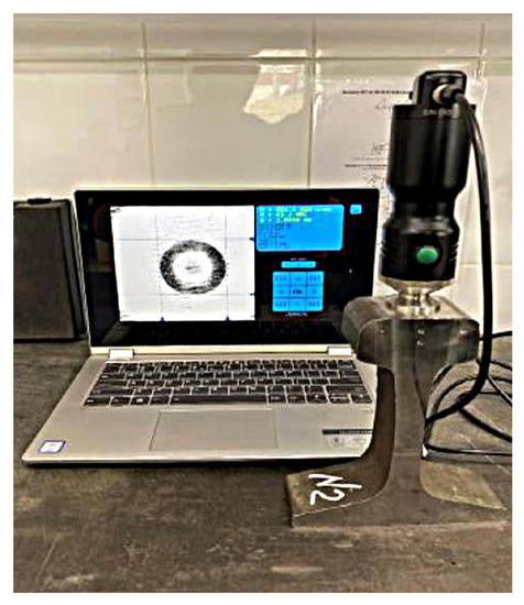
Figure 1.
Measuring the hardness of the samples with the WILSON BH3000 hardness tester.
The mechanical tension properties of the rail were determined using the Instron HDX-1000 universal rapture test machine. The blanks of samples for the tensile test were cut along the rolling direction taken from the upper part of the head in the fillet zone as close as possible to the surface at a distance of at least 150 mm from the end of the rail (Figure 2). The main dimensions of the samples are also shown in Figure 1. The mechanical characteristics were recorded automatically and calculated by the control and calculation software of the test machine. The measurement error of this machine is ±0.5%. Tensile strength mechanical characteristics were determined according to the uniaxial tension scheme on the cylindrical samples (Figure 2), which had a pick-up movement rate of 10 mm/min.
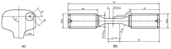
Figure 2.
The spot where the samples for tensile testing were cut and the sample dimensions. (a)—the place where the sample was cut from the rail, (b)—test specimen drawing.
The experimental results were statistically processed in Statistica (StatSoft Inc., Tulsa, OK, USA), Table Curve 2D, and Table Curve 3D software. For each value (each point in the diagram), the tests were conducted on at least 5 samples.
2.2. Cyclic Life
The cyclic life during fatigue tests is determined according to GOST 25.502 under hard loading (strain control) of the samples with a constant amplitude of the full strain (longitudinal) equal to 0.00135. Cyclic durability tests were performed using the Instron 8801 (Instron Engineering Corporation, Norwood, MA, USA) universal machine (Figure 3). This machine has built-in sensors for measuring the deformation value. Sample blanks for the test were cut along the rolling direction from the upper part of the head in the fillet area as close as possible to the surface at a distance of at least 150 mm from the end of the rail (Figure 2). The basic dimensions of the samples are also shown in Figure 1 (Loading scheme—cyclic tension-compression). Cyclic durability tests were conducted indoors at an ambient temperature of 22 °C and a relative humidity of 65%. The samples had a temperature of 22 °C before the tests. A longitudinal uniaxial cyclic load was applied to the sample, which had a loading cycle asymmetry coefficient of minus 1 and a loading frequency of 40 Hz. The test base is 5 million loading cycles. The testing was terminated when a crack or fracture in the sample formed or when the test base was reached.
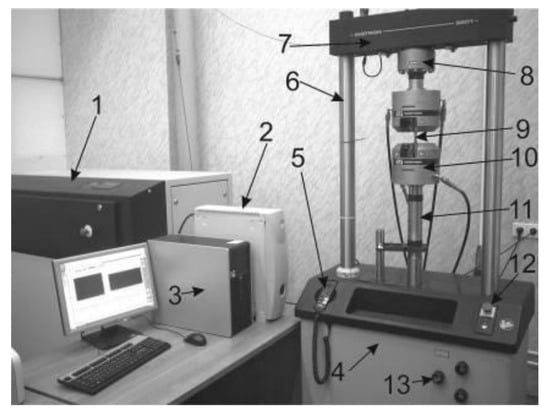
Figure 3.
Appearance of the test complex, Instron 8801. 1—hydroelectric power station, 2—controller, 3—computer, 4—power frame, 5—control panel, 6—columns, 7—rigid horizontal traverse, 8—force action sensor, 9—sample, 10—hydraulic grips, 11—hydraulic servo drive column, 12—panel for controlling the hydroelectric station, and 13—valves for controlling the stiffening beam position.
2.3. Rail Endurance Limit (Fatigue Tests)
The tests were carried out on full-profile samples (1200 + 10 mm long), cut from the rails by cold mechanical cutting methods. The loading scheme is a flat three-point symmetric bending (Figure 4). The distance between the lower supports is 1000 ± 5 mm. The upper punch is installed in the middle between the supports within 500 ± 5 mm. The samples are tested under soft loading (force control) in the position “head down” of the rail when the asymmetry of the loading cycle is plus 0.1. The test base is 2 million cycles.
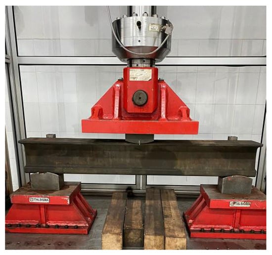
Figure 4.
Experimental plant and a general view of tests for determining the endurance limit of the rails.
Cyclic life tests are performed indoors at an air temperature of 22 °C and a relative air humidity of 65%. The temperature of the samples before testing was 22 °C.
Measuring tools or equipment must provide a cyclic load of at least 1000 kN and have a maximum permissible relative measurement error of ±3%. The maximum relative error of the sensor must be ±2%. The loading frequency is 10 Hz, with a maximum relative error of ±2%.
2.4. Residual Stresses
Residual stresses in the rail neck are determined by the divergence of the groove as a rail height difference (H2-H1) along the axis at the end of the sample before and after cutting the groove according to the scheme shown in Figure 5. The samples intended for studying residual stresses by the mechanical method were prepared on an electrochemical die-sinking and hole-contouring machine, SFE-12000M (STANKOFINEXPO, Kirov, Russia). Such equipment was chosen because no additional technological residual stresses were introduced when using this method of preparing experimental samples. Initially, a piece of the rail having a length of 600 ± 3 mm was cut off, and then a groove 6 ± 1-mm wide was cut through, and the accuracy of this size was ensured by the accuracy of manufacturing with an electrode tool.
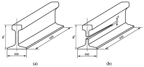
Figure 5.
Schematic of residual stress control in a track neck. (a)—rail before testing, (b)—rail after cutting for residual stresses testing.
The control of residual stresses in the rail bottom is referred to as “periodic tests” and, according to item 6.5 “Periodic tests” of GOST 51685-2013, is carried out at least once every three years. The level of residual stress in the rail bottom is determined from the full-profile samples. The samples, 1.0 ± 0.1-m long, were cut from six rails by cold mechanical cutting. It is necessary to perform abrading to a depth of 0.3 to 0.5 mm on the bearing surface of the rail bottom in the middle part of the sample, after which a strain gauge is attached to the cleaned area in the longitudinal direction according to the recommendations of the manufacturer of the sensor. The permissible relative error of the sensor shall not exceed ±1%.
3. Results and Discussion
3.1. Study of Rail Microstructure
First, the microstructures of already-used and new rails were studied. The photos of the etched microstructure of the used R65 rails and the new R65 rails are shown in Figure 6.
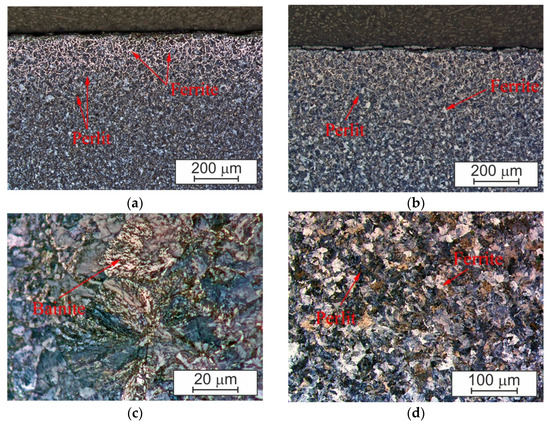
Figure 6.
Microstructure of the studied R65 rails: (a) surface of the rail after the standard service life of 494 million t-km gross; (b) new (unused before) rail in a state of delivery; (c) pearlite grain on the rail surface after the standard service life; and (d) ferrite-pearlite structure section of the rail surface after the standard service life (at a depth of ~3 mm from the surface).
The metal microstructure of the rails after operation is represented by a lamellar pearlite estimated at 2-3 points (0.3–0.4 microns) with scattered ferrite sections along the grain boundaries. The number of ferrite grains present in the used R65 rails (Figure 6d) is less than 5%, and the average size is about 0.24–0.26 µm. There is practically no perlite in the new R65 rails (Figure 6b), and bainite was not detected in the microstructure of the studied rail. When moving away from the surface of the rail rolling head, perlite acquires a more coarse-grained structure. This is related to the specificity of rail manufacturing technology. The rails taken for this study were made by hot rolling. Since the rail cools unevenly after rolling, a finer-grained structure is formed on the surface; however, when moving away from the surface of the rail head, the pearlite grain size becomes larger. Characteristic images of this structure with a larger grain are shown in Figure 6d.
A deformed structure is observed to a depth of up to 300 microns on the etched cuts from the surface of the working fillet. The amount of the decarbonized layer on the surface identified by the solid ferrite grid does not exceed 320 μm (Table 2). Local light-etched areas of a work-hardened metal are observed on the rolling surface, along which cracking develops (Figure 6a).
Table 2.
Analysis of microstructure test results.
According to the classical definition, pearlite is a structural component of steel and cast iron, a eutectoid mixture of ferrite and cementite [20]. When crystallized under normal conditions, pearlite has a lamellar structure consisting of alternating plates of pearlite and cementite [21]. The studies performed in the present work revealed numerous imperfections in the structure of lamellar pearlite, namely, an alternating “comb” type structure (Figure 7a) and breaks of cementite plates (ferrite bridges) (Figure 7b). Quite often, there are curved plates of cementite of varying thickness in the pearlite colony.
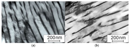
Figure 7.
Pearlite structure in the surface layer: (a) alternating pearlite structure and (b) broken structure of cementite plates.
The ferrite plates of pearlite colonies quite often have an alternating light and gray contrast. This diffraction contrast indicates that the ferrite plates are obviously divided into weakly misaligned areas as a result of elastic stresses.
The metallography of etched cuttings (Figure 6d) revealed that structurally free ferrite grains are present in the steel structure of the used rails, i.e., ferrite grains, in the volume of which there are no carbide phase particles. The relative content of such grains is small and does not exceed 5% of the steel structure. Ferrite grains, as a rule, are located in the form of interlayers along the borders of pearlite grains (Figure 6a) or at the joints of the borders of pearlite grains (Figure 6d).
Since the rails are obtained by means of rolling, the absence of line defects is important. Therefore, we conducted a rail study for the parameters of individual globular defects (ED) and line defects (EB). To identify the possibility of reutilizing rails, it is necessary to study their structure for the presence of non-metallic inclusions since such inclusions weaken the properties of steel. In general, only the shape and size of inclusions may change during operation, and the number of inclusions may only vary in the surface layer. To determine the average sizes of the inclusions, 8 samples for the new RP 65 rail and the already exploited R65 rail were studied. Eight samples were taken from different rails of each type to reproduce the results. A non-etched microstructure study showed that the average diameter of the inclusions for the new and already used rails is almost the same (Table 3). However, the length of inclusions for the latter is much greater, and at the same time, the total coefficient Ka for the used rails is still lower than the standard value.
Table 3.
Analysis of steel contamination with non-metallic inclusions.
3.2. Study of the Mechanical Properties of Rails
The studies of the mechanical properties of the rails showed that there was a slight difference in the values of the strength limits and the plastic characteristics of the new RP65 rails and the previously exploited R65 rails (Table 4, Figure 8). The obtained results demonstrated that the strength properties (σB) for the material of the previously used R65 rails are 40 MPa lower than those of the material of the new RP65 rails. However, at the same time, the plastic properties of R65 are higher by about 8.5%. This can be explained by an appropriate combination of factors. On the one hand, the previously used rails have larger stitch defects, which should lead to a decrease in plastic properties. On the other hand, the initial chemical composition of R65 contains less sulfur and phosphorus. In addition, the surface layer undergoes plastic deformation during operation and has a finer-grained structure.
Table 4.
Tensile mechanical properties.
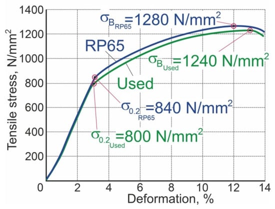
Figure 8.
Tensile diagram for the studied samples cut from R65 and RP65 rails.
The difference in the hardness of the rolling surface along the length of the rails and samples was determined by three measurements on the middle line of the rolling surface. An interval of at least 25 mm was taken for each of the three samples, which were taken from the ends and the middle part of the rail or on the rail surface (Table 5 and Table 6).
Table 5.
Hardness of the head rolling surface.
Table 6.
Hardness along the rail cross-section.
The diagram of hardness measurements along the rail section is shown in Figure 9.
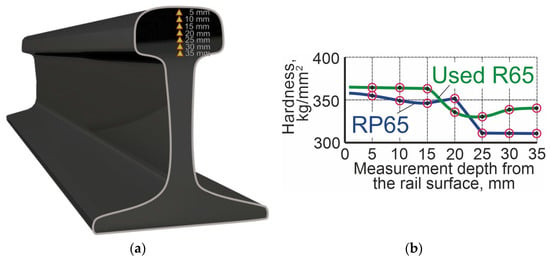
Figure 9.
Hardness measurement: (a) schematic of hardness measurement and (b) dependence of hardness on the distance from the rail surface.
Long-term operation of rails is usually accompanied by deformation and transformation of the material structure [22]. This can be justified by the hardness values obtained for the operating rails. The upper hardness limit is HB401So for the R65 rails. The hardness at a distance of 10 and 22 mm from the rolling surface must be 345–360 (HB10 mm) and 325–350 (HB25 mm). The hardness of the studied rails is within the upper boundary of these values or exceeds them, and the property changes are consistent with the changes in the rail structure. The quantitative analysis of the morphological state of the steel structure performed in this work showed that the operation of rails is accompanied by the transformation of the state of lamellar pearlite grains, namely, the destruction of cementite plates. According to the photographs in Figure 6, regardless of the position of the material’s analyzed volume (rolling surface or fillet surface), the destruction of the lamellar pearlite structure is at its maximum in the surface layer of the rails, with a thickness of less than 2 mm. However, the destruction degree of the lamellar pearlite structure depends substantially on the position of the volume to be analyzed; namely, on the rolling surface, the relative content of the broken pearlite grains is more than 2 times higher than the content in the surface layer of the working fillet.
As noted above, pearlite grains become broken during rail operation. One of the main mechanisms of such destruction during plastic deformation of the steel is cutting cementite plates by gliding dislocations [23]. The operation of rails is accompanied by an increase in the level of elastoplastic stresses in the steel. The value of elastic plastic stresses in the steel, in accordance with [24], is characterized by an excessive dislocation density and curvature-torsion amplitude of the material crystal lattice. Both of these characteristics of the steel are noted to be determined in the analysis of the bending extinction contours of the material.
The above results of the study of the rail metal after long-term operation indicate the structural transformation of the lamellar pearlite.
The change in the cementite’s elemental composition during crushing is minimal. At the initial stage of the transformation, the cementite plates of the pearlite colony are covered with gliding dislocations. This is accompanied by breaking the cementite plates into separate, weakly oriented fragments. Then, the structure of carbide changes as the plastic deformation degree of the material increases due to the stripping of carbon atoms from the cementite crystal lattice. It is worth remembering that this process is possible due to a noticeable difference in the average bond energy of carbon atoms with dislocations (0.6 eV) and iron atoms in the cementite crystal lattice (0.4 eV) [25].
The considered deformation transformations of the rail steel structure during operation on the railway should be noted as not adversely influencing the product’s cyclic life. Table 7 shows the results of testing the cyclic life of the rails. The tests were carried out on the rolling surface and, for comparison, on the cross section at a distance of at least 10 mm from the rolling surface. The tests were stopped when the sample became cracked or fractured or when the test base was reached.
Table 7.
Analysis of the cyclic life test.
The test results are considered positive if there are no fractures or cracks in all the tested samples upon reaching the test base. The test results are considered negative if the formation of a crack or fracture in at least one sample occurred within a number of loading cycles less than the test base.
The studies of the hardness along the cross section of the used rail show that the changes in properties can be considerable. Hence, the rolling of the wheel on the surface of the rail not only causes changes in hardness but can also form residual stresses at a considerable depth. The testing of the samples to determine residual stresses showed that there are considerable differences in values for the new and already used rails (Table 8). Residual stresses in the neck of the used rails are 1.42 times higher than those in the new rails (Figure 10). However, the stress values are in the upper range of values allowed for 2 mm rail use. A similar situation is observed for the middle part of the rail base. The residual stress level for the used rails is 1.25 times higher than that for the new ones (Table 9). In addition, the residual stresses of the used rails lie in the upper range of permitted values for use. Such differences in voltage values are certainly related to the operating conditions of the used R65 rails. Rolling the wheels of railway trains under a significant load deforms not only the surface layer but also the rail. This, in turn, determines the appropriate level and nature of the distribution of residual stresses. In the new rails, small residual stresses are formed at the manufacturing stage. Since the rails are made by hot rolling, internal stresses are formed in them [22].
Table 8.
Residual stress indicators in a rail neck.
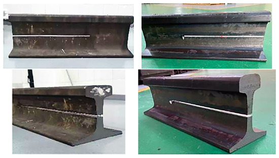
Figure 10.
Samples after residual stress control in a rail neck.
Table 9.
Analysis of test results for determining residual stresses in the middle part of the rail base.
The tests show that during operation, there are changes in the structure of the surface layer. Hardness increases along almost the entire rail section, and residual stresses are formed, but the defective surface layer of the rail also increases. The number and size of individual defects do not change, but the length of horizontally extended defects increases. In addition, cracks will form on the surface of the rail head. In general, such changes significantly affect one of the main operational properties of rails, i.e., the endurance limit.
The normalized values for using the rails in Central Asia are 2,000,000 cycles under a load of 700 kN for rails R65 and RP65. The new rails certainly meet these requirements (Table 10). In the case of the previously used rails, the maximum load under which they could operate for 2,000,000 cycles was 510 kN. Under a standard load of 700 kN, the used rails can only withstand 790,000 cycles (Figure 11a).
Table 10.
Analysis of test results for the determination of the rail endurance limit.
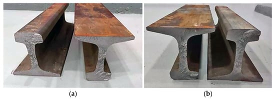
Figure 11.
Rail failure after cyclic tests: (a) under a load of 700 kN, number of cycles: 790,056; (b) fracture under a load of 600 kN, number of cycles: 1,111,966.
This result is largely due to the formation of cracks in the surface layer of the rails. A photograph of the fracture surface (Figure 11a) shows that the fracture originated on the side surface of the rail. The reason for the crack development was the zone of lateral collapse of the rail head formed under operating conditions (Figure 12a). This crack nucleus led to its fatigue development. Figure 12a clearly shows the zone of stable fracture development. It is characterized by fatigue lines representing approximate concentric contours. The focus of these contours is at the origin of the fatigue crack (Figure 12b). The surface of this zone is smooth and level. This effect is the result of cold hammering caused by repeated presses of two surfaces of the crack on each other.
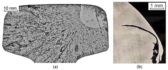
Figure 12.
Failure of a used rail after endurance limit tests. (a) A general view of the rail head and (b) the place where the crack originated on the rail fluting.
A set of experimental studies showed considerable changes in the structure of the R65 rail during its operation. The hardness of the surface layer and the rail itself increases to a sufficiently significant depth (up to 35 mm). In addition, considerable stresses are formed in the rail. It should be noted that both hardness and stress increase to the upper limit of the values allowed by the state standard (sometimes slightly exceeding it). Despite the increase in hardness and the formation of stresses, the plastic and strength properties of the rails remain almost at the same level and do not fall outside the tolerance field of the values determined by the state standard. The change in hardness is conditioned by changes in the structure of the rail. When the structure is deformed, the condition of the grains of lamellar pearlite is transformed, with the maximum amount of structure damage occurring in the surface layer of rails with a thickness of less than 2 mm. The lengths of the line defects also change, which then affects the cyclic life of the rails. New RP65 rails under a standard load of 700 kN can withstand 2,000,000 cycles. The previously used R65 rails under the same load can withstand significantly less than 790,000 cycles. They can withstand the 2,000,000 cycles determined by the state standard only under a load of 510 kN.
The changes that took place in the mechanical properties, especially in the cyclic properties, are related to both the operation intensity, structure, and mechanical composition of the R65 and RP65 rails. The analysis of the chemical composition of the analyzed steels is shown in Table 1. It shows that the chemical composition of the main alloying elements differs slightly, by no more than 0.1%. Such changes in the composition vary the properties of the steel by no more than a percentage [26]. Moreover, manganese in the RP65 steel may increase by 0.1%, and vanadium may increase by less than 0.05%. Such changes in the chemical composition will not noticeably change the mechanical properties [27,28]. The main difference between these steels is the content of sulfur and phosphorus. In RP65 steel, the content of sulfur and phosphorus can be higher by 0.01–0.02%, which somewhat reduces its plastic properties [27]. Based on this particular chemical composition, the R65 rails are designed for the main, working tracks [28], while the RP65 rails are intended for industrial routes, where the intensity of the movement is lower and there is not as much frequent deforming effect. The initial mechanical properties of the new R65 rail are slightly higher than those of the R65 rail. However, our tests have shown that both brands can withstand a certain standard load. Our studies have shown that during operation, microcracks form in the surface layer of the R65 rail, and the surface layer is decarbonized. These processes run in parallel with the processes of riveting the surface layer and the formation of internal stresses in the rails. The result is that the mechanical properties of the R65 rail (hardness and tensile strength) practically do not change or even increase by a small amount (5–10%). The formation of elongated defects in the surface layer and the formation of microcracks during operation lead to a decrease in the cyclic properties (rail endurance limit) of the rail. As a result, while the main mechanical properties of the rail material remain at the required level, the value of the rail endurance limit indicator for the used R65 rails becomes lower than that of the RP65 and no longer meets the requirements of the standard.
Based on this fact, the R65 rails can be said to have been industrially used for a standard period, which is not suitable for reutilization in the Republic of Kazakhstan. Their use is possible only in low-congested areas or areas without intensive movement (storage areas, dead ends, and other inactive routes). The number of passageways per day determines the possibility of using these rails. The regulatory framework for testing, amounting to 2,000,000 cycles that the rail must withstand, is determined by a guaranteed 20-year period of operation [29]. At the same time, they assume that up to 90 trains should pass per day. Based on the obtained results, the maximum number of cycles that the previously used R65 rail can withstand is 790 thousand, which is 2.53 times less. Therefore, it is possible to use these rails only within the sections where the traffic intensity is lower than 35 trains per day on average or various sections with non-intensive traffic, i.e., stops, dead ends, and other inactive ways. At the same time, the already-used R65 rails will provide the operation for the required period of 20 years.
At the same time, the standards and requirements for rails employed in different countries may differ significantly, as determined by rolling stock weight standards, climatic conditions, etc. Standards and requirements for the number of cycles of suitable rails can be different. Therefore, the suitability of rails for different countries can vary, necessitating meeting the standards of the country to determine the possibility of rail reutilization.
4. Conclusions
- The studies revealed that the microstructure of the rail R65 metal after operation is represented by a 2–3-point lamellar pearlite (0.3–0.4 µm) with isolated ferrite sections along the grain boundaries, while the number of ferrite grains in the previously used rails is less than 5% (average size is 0.24–0.26 µm). The depth of the deformed layer is up to 300 µm, and the value of the decarbonized layer of the surface, identified by a solid ferrite network, does not exceed 320 µm. The average diameter of non-metallic inclusions for the new RP65 and already-used R65 rails is almost the same. However, the length of inclusions for R65 is much higher. After the warranty period of R65 operation, the length of line-extended defects increases. The long-term operation of the rails is accompanied by deformation and transformation of the material structure. The hardness values of the previously used rail during the warranty period were at the level of HB 350–360.
- The quantitative analysis of the morphological state of the steel structure showed that the state of the grains of lamellar pearlite is transformed during operation. Its structure destruction is at its maximum in the upper layer of the rails, with a thickness of less than 2 mm regardless of the position of the analyzed volume. It was experimentally confirmed that the relative content of broken pearlite grains on the rolling surface was more than 2 times higher than the content in the surface layer of the working fillet.
- During the operation, a change in the structure of the upper layer was revealed. At the same time, the hardness increases along the entire rail section, and residual stresses are formed. Its level in the neck of the already used rails is 1.42 times higher than that of the new ones, and the depth of the maximum residual stresses is 2 mm, which is in the upper range of the permitted values. The values of residual stresses in the middle part of the base of the used rails are 1.25 times higher than those for the new ones, but the total level of the stress-strain state of the rail is within the permissible interval.
- Deformation transformations of the rail steel structure during their exploitation on the railway did not negatively influence the cyclic durability of the product. However, at the same time, the results of the endurance limit tests showed that the maximum load under which the used rails could run 2,000,000 cycles was 510 kN, and under a standard load of 700 kN, the already used rails could only withstand 790,000 cycles.
- Hence, if an overall level of reduction in the operational indicators of the used rails is provided, it is possible to recommend their reutilization in less critical areas at a lower level than normal to prevent sudden and difficult-to-predict failures.
Author Contributions
Conceptualization, K.Y. and D.B.; methodology, D.B.; validation, V.E.G. and A.I.K.; formal analysis, V.E.G. and A.I.K.; investigation, V.E.G.; data curation, K.Y. and D.B.; writing—original draft preparation, K.Y., N.V.M. and V.Y.S.; writing—review and editing, N.V.M. and V.Y.S.; supervision, N.V.M. and V.Y.S.; project administration, N.V.M. and V.Y.S.; funding acquisition, A.I.K. and V.E.G. All authors have read and agreed to the published version of the manuscript.
Funding
The work was supported by the Ministry of Science and Higher Education of the Republic of Kazakhstan within the framework of the BR18574141 project Theme of the project: “Comprehensive multi-purpose program for improving energy efficiency and resource saving in the energy and mechanical engineering for the industry of Kazakhstan”, for which the authors express their deep gratitude to them.
Institutional Review Board Statement
Not applicable.
Informed Consent Statement
Not applicable.
Data Availability Statement
The data presented in this study are available from the corresponding authors upon reasonable request.
Conflicts of Interest
The authors declare no conflict of interest.
References
- Dementiev, V.P.; Korneva, L.V. Railway Rails for Siberia; Irkutsk State University, University of Communications: Irkutsk, Russia, 2010. [Google Scholar]
- Kozyrev, N.A.; Dementiev, V.P. Production of Railway Rails from Electric Steel; Novokuznetsk Institute for Advanced Studies: Novokuznetsk, Russia, 2000. [Google Scholar]
- Nikolin, A.I. Improving the Processes of Welding and Heat Treatment of Rails of Mainline Railways; VNIIZhT Ministry of Railways of Russia: Moscow, Russia, 2004. [Google Scholar]
- Markov, A.A.; Kuznetsova, E.A. Rail Flaw Detection. Formation and Analysis of Signals; Ultra Print: St. Petersburg, FL, USA, 2014. [Google Scholar]
- Smirnov, L.A. Improving the quality of domestic railway rails. Bull. Sci. Tech. Econ. Inf. Ferr. Metall. 2005, 6, 43–49. [Google Scholar]
- Panda, B.; Balasubramaniam, R.; Moon, A. Microstructure and mechanical properties of novel rail steels. Mater. Sci. Technol. 2009, 25, 1375–1382. [Google Scholar] [CrossRef]
- Vitez, I.; Krumes, D.; Kladarić, I. The comparison of the properties of railway steels by codex UIC 860V and draft new European standard. Tehnički Vjesnik 2003, 10, 35–41. [Google Scholar]
- Tokmakova, E.N.; Perkov, I.E.; Ivanov, P.V.; Zagranichek, K.L. Development of rails of a new category for use in particularly difficult operating conditions. Bull. Sci. Res. Inst. Railw. Transp. (Bull. VNIIZhT) 2022, 81, 339–346. [Google Scholar] [CrossRef]
- Muravev, V.; Volkova, L.; Buldakova, I. Analysis of Stress Distribution in a Rail by Electromagnetic Acoustic Method. AIP Conf. Proc. 2016, 1785, 030016. [Google Scholar] [CrossRef]
- Lu, W.Y.; Dike, J.; Modjtahedzadeh, A. Finite element modeling of waves in a rail, in Quantitative Nondestructive Evaluation. AIP Conf. Proc. 2002, 620, 1835–1843. [Google Scholar]
- Yur’ev, A.A.; Kormyshev, V.E.; Gromov, V.E.; Ivanov, Y.F.; Shlyarova, Y.A. The physical nature of the hardening of the surface of the rails during long-term operation. Izv. Vuzov Ferr. Metall. 2021, 64, 886–894. [Google Scholar] [CrossRef]
- Ivanov, Y.F.; Gromov, V.E.; Yur’ev, A.A. Contributions of Various Mechanisms to the Hardening of Differentially Quenched Rails during Long-Term Operation. Russ. Metall. 2018, 2018, 985–989. [Google Scholar] [CrossRef]
- Office of Railroad Policy and Development, Rolling Contact Fatigue: A Comprehensive Review; U.S. Department of Transportation, Federal Railroad Administration: Washington, DC, USA, 2011. Available online: https://railroads.dot.gov/sites/fra.dot.gov/files/fra_net/89/TR_Rolling_Contact_Fatigue_Comprehensive_Review_final.pdf (accessed on 6 April 2023).
- Magel, E.; Roney, M.; Kalousek, J.; Sroba, P. The blending of theory and practice in modern rail grinding. Fatigue Fract. Eng. Mater. Struct. 2003, 26, 921–929. [Google Scholar] [CrossRef]
- De Vries, R.; Sroba, P.; Magel, E. Preventive grinding moves into the 21st century on Canadian Pacific Railroad. In Proceedings of the AREMA Annual Conference, Chicago, IL, USA, 9–12 September 2001. [Google Scholar]
- Vaičiūnas, G.; Bureika, G.; Steišūnas, S. Measurement Repeatability of Rail Wheel Loads Caused by Rolling Surface Damages. Appl. Sci. 2023, 13, 4474. [Google Scholar] [CrossRef]
- Sanchis, I.V.; Franco, R.I.; Zuriaga, P.S.; Fernández, P.M. Risk of increasing temperature due to climate change on operation of the Spanish rail network. Transp. Res. Procedia 2020, 45, 5–12. [Google Scholar] [CrossRef]
- Thaduri, A.; Garmabaki, A.; Kumar, U. Impact of climate change on railway operation and maintenance in Sweden: A State-of-the-art review. Maint. Reliab. Cond. Monit. 2021, 1, 52–70. [Google Scholar] [CrossRef]
- Klimatanpassning. “Climate Change in Sweden”. Available online: http://www.klimatanpassning.se/en/climate-changein-sweden (accessed on 6 April 2023).
- Schastlivtseva, V.M.; Mirzaev, D.A.; Yakovleva, I.L.; Okishev, K.Y.; Tabatchikova, T.I.; Khlebnikova, Y.V. Perlit in Carbon Steels; Ural Branch of the Russian Academy of Sciences: Yekaterinburg, Russia, 2006. [Google Scholar]
- Gridnev, V.N.; Gavrilyuk, V.G.; Nadutov, V.M.; Polushkin, Y.A. Redistribution of carbon and alloying elements during plastic deformation and subsequent heating of steel. FMM 1980, 50, 582–587. [Google Scholar]
- Ivanov, Y.F.; Morozov, K.V.; Peregudov, O.A.; Gromov, V.E.; Popova, N.A.; Nikonenko, E.L. Structural-phase gradients in rails during long-term operation. Probl. Ferr. Metall. Mater. Sci. 2015, 3, 59–65. [Google Scholar]
- Gavrilyuk, V.G.; Herzriken, D.S.; Polushkin, Y.A.; Filchenko, V.M. Mechanisms of cementite decay during plastic deformation. FMM 1981, 51, 147–151. [Google Scholar]
- Ivanov, Y.F.; Gromov, V.E.; Nikitina, E.N. Bainitic Structural Steel: Structure and Strengthening Mechanisms; SibSIU Publishing Center: Novokuznetsk, Russia, 2015. [Google Scholar]
- Gromov, V.E.; Peregudov, O.A.; Ivanov, Y.F. Evolution of Structural-Phase States of Rail Metal during Long-Term Operation; Publishing House of the SB RAS: Novosibirsk, Russia, 2017. [Google Scholar]
- Rezanov, V.A.; Martyushev, N.V.; Kukartsev, V.V.; Tynchenko, V.S.; Kukartsev, V.A.; Grinek, A.V.; Skeeba, V.Y.; Lyosin, A.V.; Karlina, A.I. Study of Melting Methods by Electric Resistance Welding of Rails. Metals 2022, 12, 2135. [Google Scholar] [CrossRef]
- Jena, B.K.; Gupta, N.; Singh, B.; Ahoo, G.S. Mechanical properties of low alloy high phosphorus weathering steel. J. Min. Metall. Sect. B Metall. 2015, 51, 5. [Google Scholar] [CrossRef]
- Skeeba, V.Y.; Ivancivsky, V.V.; Martyushev, N.V. Peculiarities of High-Energy Induction Heating during Surface Hardening in Hybrid Processing Conditions. Metals 2021, 11, 1354. [Google Scholar] [CrossRef]
- Ministry of Investment and Development of the Republic Kazakhstan. ST RK 2432-2013 Differentially Hardened and Non-Heat-Strengthened Railway Rails. Available online: https://pdf.standartgost.ru/catalog/Data2/1/4293741/4293741095.pdf (accessed on 10 January 2023).


Disclaimer/Publisher’s Note: The statements, opinions and data contained in all publications are solely those of the individual author(s) and contributor(s) and not of MDPI and/or the editor(s). MDPI and/or the editor(s) disclaim responsibility for any injury to people or property resulting from any ideas, methods, instructions or products referred to in the content. |
© 2023 by the authors. Licensee MDPI, Basel, Switzerland. This article is an open access article distributed under the terms and conditions of the Creative Commons Attribution (CC BY) license (https://creativecommons.org/licenses/by/4.0/).