Abstract
Stainless-steel has proven to be a first-class material with unique mechanical properties for a variety of applications in the building and construction industry. High ductility, strain hardening, durability and aesthetic appeal are only a few of them. From a specific point of view, its nonlinear stress–strain behaviour appears capable of providing a significant increase in the rotational capacity of stainless-steel connections. This, in turn, may provide significant benefits for the overall response of a structure in terms of capacity and ductility. However, the bulk of the research on stainless-steel that has been published so far has mostly ignored the analysis of the deformation capabilities of the stainless-steel connections and has mostly focused on the structural response of individual members, such as beams or columns. For such a reason, the present study aims to contribute to the general understanding of the behaviour of stainless-steel connections from a conceptual, numerical and design standpoint. After a brief review of the available literature, the influence of the use of stainless-steel for column–beam connections is discussed from a theoretical standpoint. As a novel contribution, a different approach to compute the pseudo-plastic moment resistance that takes into account the post-elastic secant stiffness of the stainless-steel is proposed. Successively, a refined finite element model is employed to study the failure of stainless-steel column–beam connections. Finally, a critical assessment of the employment of carbon-steel-based design guidelines for stainless-steel connections provided by the Eurocode 3 design (EN 1993-1-8) is performed. The findings prove the need for the development of novel design approaches and more precise capacity models capable of capturing the actual stainless-steel joint response and their impact on the overall ductility and capacity of the whole structure.
1. Introduction
Stainless-steel is a relatively new high-performance structural material with impressive mechanical, physical and aesthetic properties, including resistance to corrosion, long lifespan, high ductility, strength and strain hardening, adaptability, reliability and recyclability [1]. As opposed to the bilinear stress–strain behaviour of carbon-steel, it exhibits a markedly nonlinear stress–strain behaviour [2,3,4,5,6,7]. Such a peculiar behaviour makes stainless-steel particularly suitable for seismic design since, for instance, its high ductility can significantly increase the rotational capacity of stainless-steel connections and, as a result, the overall ductility of the structures.From a general standpoint, stainless-steel can be modelled by adopting a Ramberg–Osgood law [8] or modified versions which involve different mechanical parameters [3,9,10,11]. In order to grasp more reliably the behaviour for stainless-steel alloys with ultimate limit stresses greater than the 0.2% proof stress, for instance, Rasmussen [10] suggested a modified Ramberg–Osgood approach in which the ultimate tensile strength and strain are involved in the derivation of the stress–strain curves in addition to the conventional Ramberg–Osgood parameters (i.e., Young’s modulus, 0.2% proof stress and the curve roundness parameter n). Gardner and Nethercot [11] proposed a two-stage Ramberg–Osgood formulation which accounts for strength corner properties, initial geometric imperfection modes and residual stresses.
Some authors have focused upon the experimental characterisation of stainless-steel. In particular, the tests conducted by MacDonald et al. [12] showed that the Ramberg–Osgood model can fail significantly at strains exceeding the 0.2% total strain. The experiments carried out by Olsson in his PhD thesis [13] showed that the stress–strain curve for strains up to 2% of total strain, can be approximated by a Ramberg–Osgood curve and after that strain by a straight line. Mirabel and Real [14] analysed the flexural behaviour of stainless-steel beams both experimentally and numerically. They took into account the material nonlinearity, the effective cross-section and the variation of Young’s modulus along the length of the beam observing a good agreement with the numerical and the experimental deflection values.
The main drawbacks of using stainless-steel in civil and structural engineering are, firstly, the high production costs caused by the addition of a variety of alloying agents to the steel (i.e., iron, chromium, nickel, manganese and copper), and secondly, the significant lack of specific seismic design provisions. Actually, most of the international structural design standards such as, for instance, the Eurocode 3 design code [15,16], are primarily intended for carbon-steel structure design and only include supplementary rules for the design of stainless-steel structures [17,18,19]. The design of stainless-steel beam-to-column connections, whose behaviour has a significant impact on both local ductility requirements and overall structural performance and stability, is the focus of the current research. Unlike the response of carbon-steel joints, the response of stainless-steel joints is still not adequately addressed in the literature, which has up until now tended to focus on the behaviour of individual members (i.e., beams and columns) [20,21,22,23,24,25,26,27,28].
Due to their similar Young’s modulus, carbon-steel and stainless-steel joints with the same geometrical characteristics present the same initial joint rotational stiffness. However, the overall ductility and resilience of the structure heavily depend on the entire moment–rotation response of the joints, as well as on their ductility [29,30]. All these facts motivate the need for theoretical, computational and experimental research on stainless-steel beam-to-column connections.
In the present paper, the influence of the use of stainless-steel on beam-to-column connections is first briefly discussed from a theoretical standpoint. Successively, building on some recent considerations by the present authors [31], a novel approach to compute the (pseudo-)plastic moment resistance that takes into account the post-elastic secant stiffness of the stainless-steel is proposed. This approach is analytically effective, and it may add to the mechanical understanding of the problem by highlighting the role of a proper secant stiffness in the framework of the component method (CM). Following past contributions to the topic [31,32,33], a refined finite element model is then developed, assessed and employed to study the behaviour of the rotational capacity of stainless-steel connections and their status at failure. Finally, a critical assessment of the employment of carbon-steel-based design guidelines for stainless-steel connections provided by the Eurocode 3 design (EN 1993-1-8) is performed. The findings show the need for further development of the design approaches and more precise capacity models capable of capturing the actual behaviour of stainless-steel joints.
2. Stainless- vs. Carbon-Steel
The chemical composition of carbon-steel is rather different than that of stainless-steel. Steel with a carbon (C) content of between 0.05 and 2.1 percent by weight is classified as carbon-steel, while steel with a minimum chromium (Cr) content of 10.5 percent by weight and a maximum carbon content of 1.2 percent by weight is classified as stainless-steel [1,17].
The chemical composition strongly influences the microstructure of the steel and, consequently, its physical and mechanical properties. For example, the steel’s ductility and weldability decrease as the carbon percentage concentration increases, causing the melting point to rise too. Increasing chromium (Cr) content causes ductility to rise, on the contrary, increasing carbon and nitrogen (N) contents leads to improved performance in terms of yield and tensile strength. Moreover, the chemical composition influences the steel hardness [34].
From a mechanical point of view, the stress–strain behaviour differs considerably between the two materials. As shown in Figure 1 and Figure 2, contrary to what happens with carbon-steel, stainless-steel starts to exhibit nonlinear behaviour at relatively low-stress states and does not show a specified yield stress or a determined plateau before strain hardening: as the strain increases, the stress–strain curves exhibit a gradual loss of stiffness and significant strain-hardening. Moreover, carbon-steel exhibits a greater elongation capability in the plastic region between the yield strength and the ultimate tensile strength on account of its substantial ductility. The cold working of stainless-steel results in higher work hardening, which increases its strength and hardness capacity.
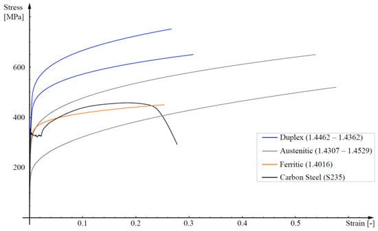
Figure 1.
A typical experimental stress–strain curve for carbon-steel S235 (black line) vs. different types of stainless-steel stress–strain curves represented by means of a modified Ramberg–Osgood model [17].
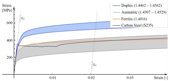
Figure 2.
Magnification of steel stress–strain curves shown in Figure 1 at small strains.
In fact, depending on the microstructure, various families of stainless-steel can be identified, with only three of them employable for structural purposes: the ferritic (0.03–0.08 wt% of carbonium, 10.50–18.00 wt% of chromium and 0–1.00 wt% of nickel (Ni)), the austenitic (0.02–0.08 wt% of carbonium, 16.50–21.00 wt% of chromium, 6.00–26.00 wt% of nickel and 0–7.00 wt% of molybdenum (Mo)) and the duplex, also referred as austenitic-ferritic (0.03 wt% of carbonium, 21.00–24.00 wt% of chromium, 3.50–6.50 wt% of nickel and 0.10–3.50 wt% of molybdenum (Mo)). The different behaviours of the three types of stainless-steels are shown in Figure 1 and Figure 2, where a typical low-grade carbon-steel response is also included for comparison.
For the sake of simplicity, in the present paper, reference will be made to a conventional austenitic stainless-steel, EN 1.4301, whose mechanical properties will be summarised later in Section 4.
3. Beam-to-Column Connections
Connections between beams and columns are important structural elements whose nonlinear behaviour must be considered in the overall structural analysis since it can influence both the local ductility demand and the overall structural stability.
Depending on the connection stiffness, beam-to-column joints have been traditionally assumed to be perfectly pinned or fully rigid in steel construction design. According to the perfectly pinned assumption, the joint has no rotational stiffness and is unable to transmit moments, but it is capable of transmitting axial and shear stresses to the connected elements. On the contrary, rotational compatibility of fully rigid connections implies the capability of the joint to also transmit the bending moments. In case of seismic actions, the susceptibility to early failures due to low-cycle fatigue effects is also important to consider. Real-world joint behaviour typically falls somewhere in the middle of the two idealised restraint conditions. A more realistic model represents the joints as a semi-continuous (semi-rigid and/or partial-strength), with a finite non-zero stiffness and a moderate flexural strength [35].
In the present paper, three different semi-rigid beam-to-column connections are considered: two different end plate connections, i.e., Extended End-Plate (EEP) and Flush End-Plate (FEP) connections, and a Top-and-Seat Angle Cleat (TSAC) connection. End plate are connections obtained by a combination of welding and bolting. The beam is, firstly, connected to the end plate by shop welding and then the end plate and the connecting column are further strengthened and secured with field bolting. Thus, the end moment of the beam is transferred through the end plate to the column flange via the bolts. These connections are additionally categorised based on the number of bolts at the flange and on the arrangement of the bolt rows.
EEPs, for instance, are characterised by an end plate extending beyond the connecting beam flanges. At least one row of bolts is placed outside of the beam flanges and on the extended portion of the end plate (see Figure 3a,b). A gusset plate, or stiffener, that is welded to the outside of the beam flange and the end plate can stiffen EEP joints. In order to strengthen the extended portion of the end plate, the stiffener is typically aligned with the web of the connecting beam (see Figure 3b).
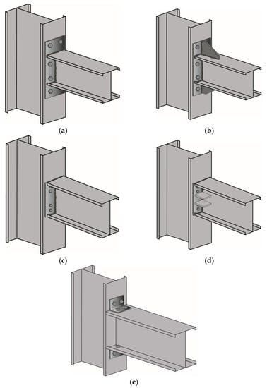
Figure 3.
A visual sketch of typical (a) unstiffened Extended End-Plate, (b) stiffened Extended End-Plate, (c) unstiffened Flush End-Plate, (d) stiffened Flush End-Plate and (e) Top-and-Seat Angle Cleat.
Alternatively, all the bolt rows in FEPs are positioned inside the connecting beam flanges and do not extend past them (see Figure 3c,d). Additionally, they can be reinforced by stiffeners welded to the web of the beam and to the end plate on either side of the web. In this case, stiffeners can be placed outside the bolt rows or in the space between the bolt rows (see Figure 3d).
Top-and-Seat Angle Cleat connections (TSAC) are, instead, primarily shear connections, which are made with seat angle cleats bolted or welded to both the supported beam and the supporting column (see Figure 3e). More specifically, it could be assumed that the bottom seat angle transmits the entire shear load to the column while the top angle resists the overturning moments from the beam, improving the rigidity of the connection and its overall stability.
Given the significant ductility of stainless-steel, the overall ductility of the structure is significantly increased, as well as the rotational capacity of stainless-steel connections.
Unfortunately, the behaviour of stainless-steel connectors has not received proper attention up until now. Among the authors who address the topic, we may cite Elflah et al. [29,30] who investigated the behaviour of stainless-steel beam-to-column joints using both numerical simulations and physical experiments and Eladly [33] who implemented a robust 3-dimensional FE model that is in good agreement with the findings of Elflah et al. [29]. Hasan et al. [36] focused on the behaviour of stainless-steel top-seat angle joints and Yuan et al. [37] investigated the resistance of austenitic and duplex T-stubs under tension using both experimental and computational analysis.
Following some recent considerations by the present authors [31], in the next Section a simple proposal for assessing the resistance of stainless-steel beam-to-column joints will be presented and discussed.
4. Analytical Evaluation of the Joint Resistance
Understanding how a connection behaves under varying loading conditions can be effectively visualised by plotting the connection’s moment–rotation curve. In this respect, the moment–rotation curve sheds light on three main characteristics: stiffness, resistance and rotational capacity.
According to EC3 [16], is the moment magnitude corresponding with a significant value of plastic deformation rather than the connection’s maximum moment capacity. However, the existing design standards, such as EC3, have been developed for carbon-steel without considering stainless-steel’s ductility and mechanical properties.
Naturally, the weakest component failing leads to the onset of joint failure. When a joint component fails due to ductility, considerable amounts of stress must be transferred between the joint elements, resulting in significant increases in the moment resistance until the ultimate failure. The starting point in the approach suggested here is that the approximation of the nonlinear behaviour of stainless-steel by a bilinear elasto-plastic model, as it is customary for carbon-steel, encompasses challenging problems in the definition of the slope of the tracts. In the classic theory of plasticity two concepts are widely used, i.e., the secant modulus and the tangent, or incremental modulus, of the stress–strain curve [32]. The first approach assumes that the initial stiffness of the material can be substituted by the secant stiffness corresponding to a certain point given, for example, by a characteristic deformation value. The tangent, or incremental modulus approximation, makes use of the tangent to the curve to represent the stiffness of the material that varies along the curve. In this framework, the initial stiffness coincides with the linearly elastic one . However, the use of the tangent, or incremental modulus approximation, can be rather problematic, given its strong variability and therefore the definition of appropriate strain–stress relationships is crucial in engineering applications, especially when slender elements are involved. In fact, complex phenomena, such as inelastic buckling, are open to misinterpretation and paradoxes when the assumed plasticity model fails [38,39,40]. From a purely technical standpoint, the offset yield is the standard yield point estimation strategy widely used for stainless-steel. The offset yield strength method derives the yield strength from where a specific offset parallel to the slope crosses the stress–strain curve and estimates the material modulus in the elastic region of the curve. The yield stress of stainless-steel is commonly defined as the stress at an offset of 0.2% plastic strain, which is also referred to as the 0.2% proof strength (). Figure 4 shows the stress–strain curve for the stainless-steel representative of the end plate steel (type EN 1.4301). The point (282, 0.007) on this curve corresponds to the 0.2% proof strength.
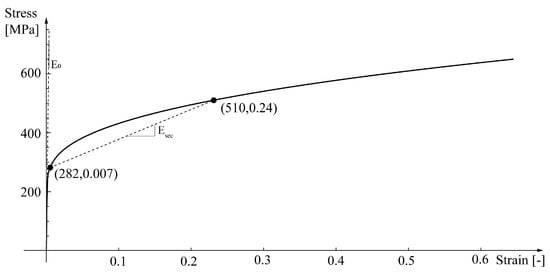
Figure 4.
Stress–strain curve of stainless-steel type EN 1.4301. The points (282, 0.007) and (510, 0.24) on this curve correspond to the 0.2% proof strength ( and to the yield strength (, respectively.
As a result, the strain at is quite small, while the stiffness remains significant. This is very different from what occurs with carbon-steel. In light of this, for calculating according to the EC3 CM [16], it is here proposed to define for stainless-steel an equivalent material strength , as an alternative to the 0.2% offset strength. The equivalent for the endplate material is here taken as the stress at which the secant stiffness, that is the line connecting the points at and , is equal to , 510 MPa, a value which is likely to account well for the actual mean behaviour of stainless-steel in the region of interest for the calculations, see Figure 4. Furthermore, the chosen value of the secant stiffness linearises the stress–strain relationship starting from the limit of the proportional stress–strain tract.
It can be observed that in the case at hand the secant stiffness makes the stress–strain work between 0.007 and 0.4 approximatively equivalent to the work corresponding to the real stress–strain relationship, with 0.4 as the maximum local limit generally attained for the connections under consideration, as it will be assessed using the finite elements analyses. However simple, this approach has recently proved very effective also in the case of long-debated instability problem, such as the one of the torsional buckling of a cruciform column [41]. EC3 [16] provides the initial rotational stiffness, , and the moment resistance, as follows:
represents the Young’s modulus, is the lever arm, and are the elastic stiffness and the effective design resistance of the spring resembling the ith joint component. No relationship has been provided in EC3 to calculate the rotation capacity. Given the scarcity of experimental tests on stainless-steel beam-to-column connections, in order to have a verification benchmark, reference will be made here to the results by Elflah et al. [29,30]. Reference is thus made for the geometrical and the connections’ material properties to [29], see Figure 5 and Table 1.
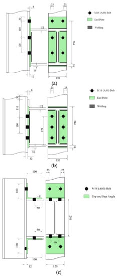
Figure 5.
Geometrical properties of investigated joints. (a) Extended End-Plate (EEP); (b) Flush End Plate (FEP); (c) Top-and-Seat Angle Cleat (TSAC).

Table 1.
Material properties.
On account of Equation (2) and of the CM, the plastic moment resistance is evaluated making use, first, of the value () and, then, of the proposed value ().
In order to calculate the plastic moment resistance from experimental moment–rotation curves, the method proposed by Zanon and Zandonini [42] is here used. According to this method, the intersection of two linear branches of the moment–rotation curve is used to determine the pseudo-plastic moment resistance , as shown in Figure 6.
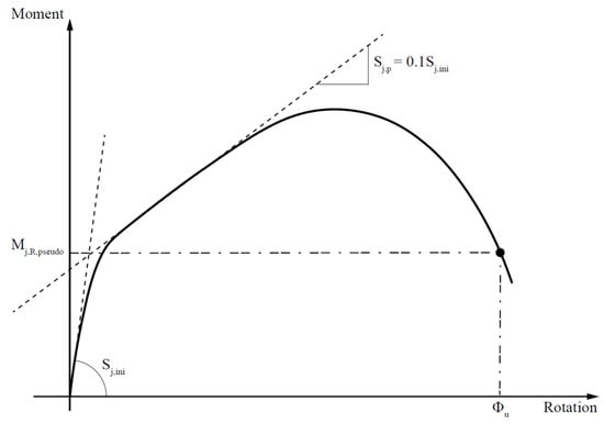
Figure 6.
Derivation of pseudo-plastic moment resistance using Zanon and Zandonini method [42].
Therefore, on account of the experimental moment–rotation curve provided by Elflah [29], see Figure 7, the values for the pseudo-plastic moment resistance are calculated and collected, together with the results from the EC3 prescriptions for EN 1.4301 stainless-steel and from the proposed method, see Figure 8.
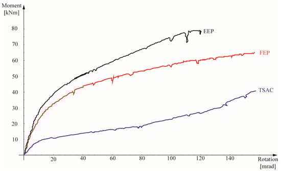
Figure 7.
Comparison of experimental moment–rotation relationships for EN 1.4301 stainless-steel.
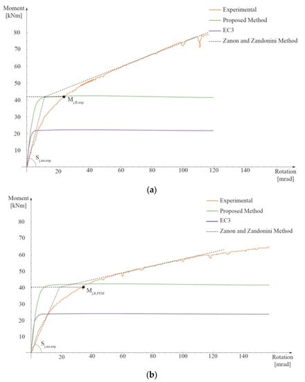
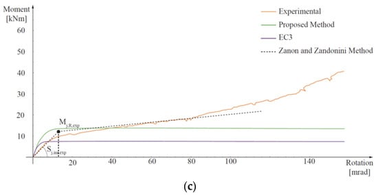
Figure 8.
Comparison of moment-rotation curves obtained using Eurocode 3 (EC3) and proposed methods with the experimental ones [29] (solid lines) and estimation of the experimental pseudo-plastic moment resistance () (black dot) by means of Zanon and Zandonini method [42] (dashed lines): (a) Extended End-Plate (EEP), (b) Flush End-Plate (FEP), (c) Top-and-Seat Angle Cleat connection (TSAC).
5. Discussion of the Results from the Proposed Analytical Approach
Figure 8 compares the moment–rotation curves derived using the EC3 approach (note that, measured instead of characteristic values of the materials properties were used) and the suggested method in light of the data derived from experimental results. The experimental moment capacity, , obtained using the method of Zanon and Zandonini [42] is also reported.
Table 2 collects all the results and it is evident that EC3 [16] rules underestimate the plastic moment capacity by an average of 49% with respect to the experimental findings. This is not surprising, because such a discrepancy has been pointed out in previous studies [43,44,45,46,47,48,49]. The results from Table 2 also show how the use of the proposed equivalent yield strength improves the computed moment resistance’s accuracy to 90% with respect to the experimental findings.
Table 2.
Comparison of the plastic moment evaluated with EC3, , proposed method, , and the method of Zanon and Zandonini [42] from the experimental curves, , (Units: kNm).
With respect to the initial rotational stiffness, , EC3 analytical predictions substantially coincide with those from the proposed method, which does not affect the initial stiffness of the joint, which is essentially dependent on the elastic moduli of the material. The results of the EC3 and the proposed method are therefore collected in Table 3 and labelled as , together with those graphically derived from the moment–rotation experimental curves, [29,30] (see Figure 8). It is evident that for all analysed connections, the CM leads to an important overestimation of the initial stiffness (i.e., about 115% on average). This fact has been already observed in previous studies [47] and it tends to be more marked with the reduction of the rotational stiffness of the connection, that is, the CM tends to overestimate the initial stiffness more for the quasi-pinned connections than for the quasi-fixed ones.
Table 3.
Comparison of the initial rotational stiffness evaluated with the component method, , and the method of Zanon and Zandonini [42] from the experimental curves (Figure 8), , (Unit: kNm/rad).
Additionally, it must be pointed out that the rotational capacity of steel joints—the angle at which the connection can rotate while maintaining the resistance at the pseudo- plastic level—is not specifically defined in the EC3, and the length of the yield plateau on the theoretical moment–rotation curve can be used to assess the joint’s ductility.
For carbon-steel grades, the suggested minimum capacity is typically at least 30 mrad and ductility requirements aim to avoid brittle failures, allowing for reasonably large inelastic deformations. The elongation capacity of austenitic steel can exceed 45%, about 10–15 percentage points higher than carbon-steel, so stainless-steel exhibits a larger ductility capacity [1,4,50].
Table 4 summarises the plastic mechanisms that can be predicted in accordance with EC3 requirements. For each joint under consideration, ductile failure mechanisms are predicted. However, potentially, the stainless-steel’s capacity to strain-harden may also result in a considerable increase in moment resistance, leading to a tensile failure of the bolts.
Table 4.
Plastic mechanisms calculated according to EC3.
6. Assessment of the Plastic Mechanism by FE Modelling of the Joints
In order to analyse the failure of the points and the plastic strains attained along the loading process, all three types of column–beam connections tested by Elflah et al. [30,31] have been modelled by means of the general purpose nonlinear finite element modelling program ABAQUS 2022 HF4 library [51]. Accordingly, all the geometric and material properties of the connections were derived from [29,30] and are summarised in Figure 5 and Table 1. Accordingly, the fabrication of Beams and Columns involves the use of Identical I-section profiles with dimensions of I240 × 120 × 12 × 10 (depth × width × flange thickness × web thickness). For the FEP and EEP, plates with dimensions of 260 × 120 × 8 and 330 × 120 × 8 are utilised, respectively, whereas TSAC makes use of angle cleats with dimensions of 100 × 100 × 8. All joints are fastened using M16 A4-80 bolts.
The analysed beam and column were both 1500 mm in length. At a distance of 1470 mm from the column flange, a vertical monotonic load was applied to the end of the beam, with constrained out-of-plane deformations (see Figure 9).
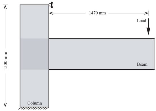
Figure 9.
Sketch of loading and boundary conditions.
In order to mimic the interactions between welded links and prevent relative motion between components, the welds’ behaviour was assumed to be stiff and a tie constraint was used. In full accordance with the experimental setup described in [29], the boundary conditions implemented in the FE analysis restrained all degrees of freedom by applying a fixed end condition to the bottom of the column and preventing horizontal displacements of the column top side in the plane of loading.
The steel plates between the beam and column were modelled using quadrilateral four-node shell elements (S4R element), which have three rotational and three translational degrees of freedom at each node. In order to obtain a structured mesh with optimised mesh sizes in all different parts of the geometrical model, the mesh density was examined at various sizes (2–40 mm). A fine mesh (5 mm) discretises areas subjected to large stresses, while a coarser mesh (20 mm) was used for all the other model’s regions. A sensitivity analysis showed that five through-thickness Simpson integration points are enough to supply accurate results. The FE model includes the nonlinear effect induced by significant deformation (i.e., geometric nonlinearity) to adequately capture the effect of the nonlinear stress–strain behaviour of the joint. Building on previous successfully approaches [52,53], stainless-steel bolts were modelled by means of Cartesian elements from the ABAQUS library [51].
Contacts were modelled with the well-established “master” and “slave” surfaces. A “hard contact” condition was also adopted as contact pressure separation condition to enable for complete transmission of compressive loads and separation following contact. A penalty technique with a friction coefficient of 0.3 was used to calculate the tangential response of all contact surfaces.
The main values employed to characterise the materials are collected in Table 1, i.e., elastic modulus , plastic strain at fracture and strain-hardening coefficients n and m for the Ramberg–Osgood model [8] of the following equation:
where
and, for austenitic stainless-steel [3]
The FE models replicated very closely the results from experimental tests [29] and the failure mechanisms for all specimens at the deformation corresponding to the maximum load were found in very good agreement with the tests [31], see Figure 10. For any additional information about the adopted numerical procedure and its validation, the reader is directed to [31].
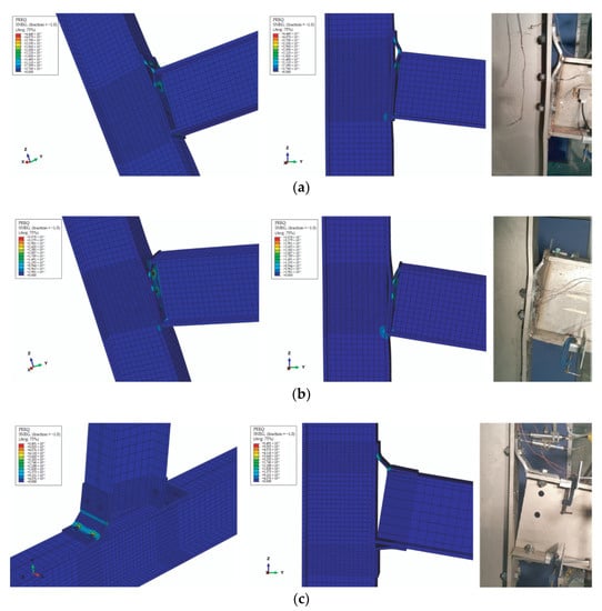
Figure 10.
Comparison of numerical (left) and experimental (right, reprinted with permission from Ref. [29]) failure modes. (a) Extended End-Plate (EEP), (b) Flush End-Plate (FEP), (c) Top-and-Seat Angle Cleat connection (TSAC).
Based on experimental testing [29], the rotation in connection, , was defined as the ratio of the relative horizontal displacement of the beam flanges to the distance between the centrelines of the same flanges. In this regard, the loading point (see Figure 9) in one beam flange and its opposite point on the other flange is taken into account in order to calculate the rotation. The bending moment was evaluated by multiplying the load applied at the beam end by the perpendicular distance from the loading point to the column flange.
Figure 10 shows the equivalent plastic strains attained throughout the connection and it is evident that, on average, up to the moment when the first instance of bolt fracture takes place, they result in the range of 0.15–0.40, not exceeding 0.55 at the break.
Both FEP and EEP models displayed large plastic deformations at the column flange and at the end plates. TSAC also exhibited large inelastic deformations in column flange and angle cleats. Overall, the numerical models correctly identified the failure of the connectors corresponding to the top bolt row in the form of tensile fracture of the connectors corresponding to the top bolt rows.
Table 5 collects the ultimate failure modes obtained using the FE analyses. As supposed, the strain hardening capabilities of stainless-steel actually allow for a significant increase in the moment resistance, which can finally lead to the tensile failure of the bolts. Accordingly, the ultimate rotation attains a range of values ranging from 118 to 159 mrad, which exceeds the recommended limit for dissipative joints (i.e., 30 mrad) [43,44].
Table 5.
Plastic mechanisms, ultimate failure mode and ductility.
It is worth pointing out that the ultimate failure mode results different from the plastic mechanism predicted by the CM (EC3) as reported for comparison in the first column of Table 5. In fact, regardless of the steel grades, EC3 [16] assumes a plastic distribution of forces, with some requirements and limitations with respect to a possible (tension) failure of bolts. Actually, the stress distribution at the joint changes as the connection rotates, and it may differ from that calculated by the CM, primarily on account of the strain hardening. As a result, there may be substantial variations between the plastic mechanism predicted using the CM and the actual ultimate failure mode.
On the basis of the FE analyses, two additional parameters are reported in order to characterise the behaviour of the examined stainless-steel joints:
- 1
- The ratio (ρj) of the ultimate moment (Mj,u) to the pseudo-plastic resistance (Mj,R), usually called the plastic over-strength:
- 2
- The ratio (ρj) of the rotation capacity of the joint (ϕu) to the rotation value corresponding to the pseudo-plastic resistance (), usually defined as the joint ductility:
It is found that the values of the over-strength ratio ρi vary in a range from 1.63 to 2.83, while the ductility µj varies in a range from 2.65 to 4.45. Therefore, as thought, all specimens show considerable inelastic deformations prior to failure.
Figure 11 shows the forces in the bolts’ vs. the joints’ rotation. It can be noticed that in the case of EEP and FEP joints a significant rotation occurs until fracture, with an almost constant force at the middle bolt row 2 for the EEP joint and at the top bolt row 1 for the FEP joint. Conversely, in the case of TSAC the force in bolt row 1 steadily increases until fracture.
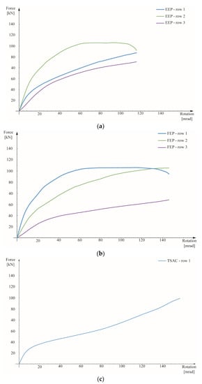
Figure 11.
Bolt forces vs. joint rotation curves. (a) Extended End-Plate (EEP), (b) Flush End-Plate (FEP), (c) Top-and-Seat Angle Cleat (TSAC).
7. Conclusions
In the present paper the influence of the use of stainless-steel for beam-to-column connections has been first briefly discussed from a theoretical standpoint, and successively a novel approach to compute by means of the component method the pseudo-plastic moment resistance of the joint by taking into account the post-elastic secant stiffness of the stainless-steel has been proposed. In order to assess the actual failure of the considered stainless-steel connections, reference has been made to a finite element model, which had already been extensively verified [31]. On these bases, a critical assessment of the employment of carbon-steel-based design guidelines for stainless-steel connections provided by the Eurocode 3 design (EN 1993-1-8) has been carried out. It has been clearly shown that, since the guidelines of EC3 were specifically designed for carbon-steels and disregards the actual strain-hardening ability of stainless-steels, the EC3 CM based on the material proof strength () is not able to accurately match the experimental results. Moreover, the moment resistance is considerably underestimated when the EC3 procedure is applied by simply replacing the yield strength with the proof strength.
Conversely, the proposal of a straightforward alternative definition for the equivalent yield strength, , built on the idea of an equivalent elastic-plastic material with a small post-elastic (secant) stiffness has been shown to be capable of providing results much more in line with the experimental findings. Overall, the present study clearly indicates the need for the development of novel design approaches and more precise capacity models capable of capturing the actual behaviour of stainless-steel joints. As a consequence, a proposal of a power model capable of estimating the moment–rotation behaviour of beam-to-column connections made of austenitic and duplex grades of stainless-steel is currently under development in order to predict the entire moment–rotation behaviour including the rotation capacity and the maximum moment on the basis of some key connection features such as initial and strain-hardening stiffness, reference plastic moment and curve shape factor.
Author Contributions
Methodology, G.D.C. and F.G.; software, S.S. and R.S.; validation, S.S.; formal analysis, I.M.; investigation, S.S.; data curation, S.S.; writing—original draft preparation, I.M., G.D.C. and F.G.; writing—review and editing, I.M., G.D.C. and F.G.; visualisation, F.G.; supervision, R.S., G.D.C. and F.G. All authors have read and agreed to the published version of the manuscript.
Funding
This research received no external funding.
Institutional Review Board Statement
Not applicable.
Informed Consent Statement
Not applicable.
Data Availability Statement
Data sharing not applicable. No new data were created or analyzed in this study.
Conflicts of Interest
The authors declare no conflict of interest.
References
- Tylek, I.; Kuchta, K. Mechanical properties of structural stainless steels. Czas. Tech. 2014, 4-B, 59–80. [Google Scholar]
- Baddoo, N.R. Stainless steel in construction: A review of research, applications, challenges and opportunities. J. Constr. Steel Res. 2008, 64, 1199–1206. [Google Scholar] [CrossRef]
- Real, E.; Arrayago, I.; Mirambell, E.; Westeel, R. Comparative study of analytical expressions for the modelling of stainless steel behaviour. Thin-Walled Struct. 2014, 83, 2–11. [Google Scholar] [CrossRef]
- Gardner, L. Stability and design of stainless steel structures–Review and outlook. Thin-Walled Struct. 2019, 141, 208–216. [Google Scholar] [CrossRef]
- Arrayago, I.; Real, E.; Gardner, L. Description of stress–strain curves for stainless steel alloys. Mater. Des. 2015, 87, 540–552. [Google Scholar] [CrossRef]
- González-de León, I.; Arrayago, I.; Real, E.; Nastri, E. Rotation capacity of cold-formed stainless steel RHS beams under cyclic loading. J. Constr. Steel Res. 2022, 192, 107199. [Google Scholar] [CrossRef]
- González-de León, I.; Nastri, E.; Arrayago, I.; Montuori, R.; Piluso, V.; Real, E. Experimental study on stainless steel tubular members under cyclic loading. Thin-Walled Struct. 2022, 181, 109969. [Google Scholar] [CrossRef]
- Ramberg, W.; Osgood, W.R. Description of Stress-Strain Curves by Three Parameters; Technical Note No. NACA-TN-902; National Advisory Committee for Aeronautics: Washington, DC, USA, 1943.
- Hill, H.N. Determination of Stress-Strain Relations from “Offset” Yield Strength Values; Technical Note No. 927; Aluminum Co of America: Pittsburgh, PA, USA, 1944. [Google Scholar]
- Kim, J.R. Rasmussen, Full-range stress–strain curves for stainless steel alloys. J. Constr. Steel Res. 2003, 59, 47–61. [Google Scholar]
- Gardner, L.; Nethercot, D.A. Numerical Modeling of Stainless Steel Structural Components—A Consistent Approach. J. Struct. Eng. 2004, 130, 1586–1601. [Google Scholar] [CrossRef]
- MacDonald, M.; Rhodes, J.; Taylor, G.T. Mechanical properties of stainless steel lipped channels. In Proceedings of the 15th International Specialty Conference on Cold-formed Steel Structures, St. Louis, MO, USA, 19–20 October 2000; University of Missouri-Rolla: Rolla, MO, USA, 2000; pp. 673–686. [Google Scholar]
- Olsson, A. Stainless Steel Plasticity—Material Modelling and Structural Applications. Ph.D. Thesis, Department of Civil and Mining Engineering, Luleå University of Technology, Luleå, Sweden, 2001. [Google Scholar]
- Mirambell, E.; Real, E. On the calculation of deflections in structural stainless steel beams: An experimental and numerical investigation. J. Constr. Steel Res. 2000, 54, 109–133. [Google Scholar] [CrossRef]
- EN 1993-1-1; Eurocode 3: Design of Steel Structures—Part 1-1: General Rules and Rules for Buildings. British Standards Institution, CEN: London, UK, 2005.
- EN 1993-1-8; Eurocode 3: Design of Steel Structures—Part 1-8: Design of Joints. British Standards Institution, CEN: London, UK, 2005.
- EN 1993-1-4; Eurocode 3: Design of Steel Structures—Part 1-4: General Rules-Supplementary Rules for Stainless Steels. British Standards Institution, CEN: London, UK, 2015.
- AISC 27; Design Guide 27: Structural Stainless Steel. American Institute of Steel Construction: Chicago, IL, USA, 2013.
- SEI/ASCE, 8-02; Specification for the Design of Cold-Formed Stainless Steel Structural Members. American Society of Civil Engineers: Reston, VA, USA, 2002.
- Shamass, R.; Guarracino, F. Numerical and analytical analyses of high-strength steel cellular beams: A discerning approach. J. Constr. Steel Res. 2020, 166, 105911. [Google Scholar] [CrossRef]
- Eladly, M.M.; Schafer, B.W. Numerical and analytical study of stainless steel beam-to-column extended end-plate connections. Eng. Struct. 2021, 240, 112392. [Google Scholar] [CrossRef]
- Chen, X.; Real, E.; Yuan, H.; Du, X. Design of welded stainless steel I-shaped members subjected to shear. Thin-Walled Struct. 2020, 146, 106465. [Google Scholar] [CrossRef]
- Huang, Y.; Young, B. Structural performance of cold-formed lean duplex stainless steel columns. Thin-Walled Struct. 2014, 83, 59–69. [Google Scholar] [CrossRef]
- Xu, Y.; Zheng, B.; Zhang, M. Capacity prediction of cold-formed stainless steel tubular columns using machine learning methods. J. Constr. Steel Res. 2021, 182, 106682. [Google Scholar] [CrossRef]
- Kucukler, M.; Xing, Z.; Gardner, L. Behaviour and design of stainless steel I-section columns in fire. J. Constr. Steel Res. 2020, 165, 105890. [Google Scholar] [CrossRef]
- Liaqat, A.; Khan, S.; Iqbal, N.; Bashmal, S.; Hameed, H.; Bai, Y. An experimental study of damage detection on typical joints of jackets platform based on electro-mechanical impedance technique. Materials 2021, 14, 7168. [Google Scholar] [CrossRef]
- Shamass, R.; Cashell, K. Analysis of stainless steel-concrete composite beams. J. Constr. Steel Res. 2019, 152, 132–142. [Google Scholar] [CrossRef]
- Zhou, Y.; Uy, B.; Wang, J.; Li, D.; Huang, Z.; Liu, X. Behaviour and design of stainless steel-concrete composite beams. J. Constr. Steel Res. 2021, 185, 106863. [Google Scholar] [CrossRef]
- Elflah, M.; Theofanous, M.; Dirar, S.; Yuan, H. Behaviour of stainless steel beam-to-column joints—Part 1: Experimental investigation. J. Constr. Steel Res. 2019, 152, 183–193. [Google Scholar] [CrossRef]
- Elflah, M.; Theofanous, M.; Dirar, S. Behaviour of stainless steel beam-to-column joints-part 2: Numerical modelling and parametric study. J. Constr. Steel Res. 2019, 152, 194–212. [Google Scholar] [CrossRef]
- Sarfarazi, S.; Shamass, R.; Della Corte, G.; Guarracino, F. Assessment of Design Approaches for Stainless-Steel Joints Through an Equivalent FE Modelling Technique. ce/papers 2022, 5, 271–281. [Google Scholar] [CrossRef]
- Shamass, R.; Alfano, G.; Guarracino, F. An investigation into the plastic buckling paradox for circular cylindrical shells under non-proportional loading. Thin-Walled Struct. 2015, 95, 347–362. [Google Scholar] [CrossRef]
- Eladly, M.M. Behaviour of stainless steel beam-to-column bolted connections–Part 1: Simplified FE model. J. Constr. Steel Res. 2020, 164, 105784. [Google Scholar] [CrossRef]
- Díaz, C.; Martí, P.; Victoria, M.; Querin, O.M. Review on the modelling of joint behaviour in steel frames. J. Constr. Steel Res. 2011, 67, 741–758. [Google Scholar] [CrossRef]
- Steels, O. Practical Guidelines for the Fabrication of Duplex Stainless Steels; Metallurgy 3; International Molybdenum Association (IMOA): London, UK, 2014. [Google Scholar]
- Hasan, M.J.; Al-Deen, S.; Ashraf, M. Behaviour of top-seat double web angle connection produced from austenitic stainless steel. J. Constr. Steel Res. 2019, 155, 460–479. [Google Scholar] [CrossRef]
- Yuan, H.; Gao, J.; Theofanous, M.; Yang, L.; Schafer, B. Initial stiffness and plastic resistance of bolted stainless steel T-stubs in tension. J. Constr. Steel Res. 2020, 173, 106239. [Google Scholar] [CrossRef]
- Shamass, R.; Alfano, G.; Guarracino, F. On elastoplastic buckling analysis of cylinders under nonproportional loading by differential quadrature method. Int. J. Struct. Stab. Dyn. 2017, 17, 1750072. [Google Scholar] [CrossRef]
- Mascolo, I.; Modano, M.; Fiorillo, A.; Fulgione, M.; Pasquino, V.; Fraternali, F. Experimental and Numerical Study on the Lateral-Torsional Buckling of Steel C-Beams with Variable Cross-Section. Metals 2018, 8, 941. [Google Scholar] [CrossRef]
- Piluso, V.; Pisapia, A.; Rizzano, G. Local buckling of aluminium channels under uniform compression: Theoretical analysis and experimental tests. Thin-Walled Struct. 2022, 179, 109511. [Google Scholar] [CrossRef]
- Guarracino, F.; Simonelli, M. The torsional instability of a cruciform column in the plastic range: Analysis of an old conundrum. Thin-Walled Struct. 2017, 113, 273–286. [Google Scholar] [CrossRef]
- Zanon, P.; Zandonini, R. Experimental analysis of end plate connections. Proceedings of the state of the art workshop on connections and the behavior of strength and design of steel structures. Cachan 1998, 10, 41–51. [Google Scholar]
- Coelho, A.M.G.; Bijlaard, F.S.; da Silva, L.S. Experimental assessment of the ductility of extended end plate connections. Eng. Struct. 2004, 26, 1185–1206. [Google Scholar] [CrossRef]
- Coelho, A.M.G.; Bijlaard, F.S. Experimental behaviour of high strength steel end-plate connections. J. Constr. Steel Res. 2007, 63, 1228–1240. [Google Scholar] [CrossRef]
- Kong, Z.; Kim, S.E. Moment-rotation behavior of top-and seat-angle connections with double web angles. J. Constr. Steel Res. 2017, 128, 428–439. [Google Scholar] [CrossRef]
- Simoes, D.S.L.; Santiago, A.; Vila, R.P. Post-limit stiffness and ductility of end-plate beam-to-column steel joints. Comput. Struct. 2002, 80, 515–531. [Google Scholar] [CrossRef]
- Della Corte, G.; Terracciano, G.; Landolfo, R. Review of experimental data on the moment-rotation response of steel bolted end- plate beam to column joints. In Proceedings of the Second European Conference on Earthquake Engineering, Istanbul, Turkey, 25–29 August 2014. [Google Scholar]
- Della Corte, G.; Landolfo, R. Lateral loading tests of built-up battened columns with semi-continuous base-plate connections. J. Constr. Steel Res. 2017, 138, 783–798. [Google Scholar] [CrossRef]
- Della Corte, G.; Cantisani, G.; Landolfo, R. Battened Steel Columns with Semi-Continuous Base Plate Connections: Experimental Results vs. Theoretical Predictions. In Key Engineering Materials; Trans Tech Publications Ltd.: Stafa-Zurich, Switzerland, 2018; Volume 763, pp. 243–250. [Google Scholar] [CrossRef]
- Sun, Y.; Zhao, O. Material response and local stability of high-chromium stainless steel welded I-sections. Eng. Struct. 2019, 178, 212–226. [Google Scholar] [CrossRef]
- ABAQUS. Analysis User’s Guide. Version 2022 HF4. ABAQUS; Dassault Systèmes Simulia Corp.: Providence, RI, USA, 2012. [Google Scholar]
- Khalkhali, A.; Miandoabchi, E. The application of equivalent modeling of joints for bending simulation of hybrid aluminum/high strength steel thin-walled sections joined by clinching. Thin-Walled Struct. 2020, 157, 107089. [Google Scholar] [CrossRef]
- Grujicic, M.; Snipes, J.; Ramaswami, S.; Abu-Farha, F. Self-piercing riveting process and joint modeling and simulations. Solids Struct. 2014, 3, 20–29. [Google Scholar]


Disclaimer/Publisher’s Note: The statements, opinions and data contained in all publications are solely those of the individual author(s) and contributor(s) and not of MDPI and/or the editor(s). MDPI and/or the editor(s) disclaim responsibility for any injury to people or property resulting from any ideas, methods, instructions or products referred to in the content. |
© 2023 by the authors. Licensee MDPI, Basel, Switzerland. This article is an open access article distributed under the terms and conditions of the Creative Commons Attribution (CC BY) license (https://creativecommons.org/licenses/by/4.0/).