Article

Structure–Property Relationship in High-Strength Aluminum Alloys/Stainless Steel Brazed Joints

Chair of Composites and Material Compounds, Institute of Materials Science and Engineering, Faculty of Mechanical Engineering, Chemnitz University of Technology, 09111 Chemnitz, Germany
*
Author to whom correspondence should be addressed.
Metals 2023, 13(2), 242; https://doi.org/10.3390/met13020242
Submission received: 3 January 2023 / Revised: 24 January 2023 / Accepted: 25 January 2023 / Published: 27 January 2023
(This article belongs to the Special Issue Welding and Joining of Dissimilar Materials)

Abstract

:
In many industrial sectors, for example, aerospace, automotive and high-performance electronic industries, there is a significant need to join dissimilar materials. In the case of medium-strength aluminum alloys, joints are commonly manufactured using Al-Si brazing fillers with a melting temperature of 575 °C. In comparison to medium-strength aluminum alloys, high-strength aluminum alloys exhibit lower melting temperatures. Therefore, the joining possibilities are limited. Due to the lower melting temperature of about 500 °C, Al-Ag-Cu brazing fillers allow the joining of these alloys. In this study, high-strength aluminum alloys/stainless steel joints were produced via induction brazing and vacuum furnace brazing. The mechanical properties of the joints were determined using tensile shear tests as well as fatigue tests at ambient temperature. The joints produced via induction brazing at 520 °C without holding time reached a maximum tensile shear strength of 32 MPa. The joints failed in the braze metal close to the reaction zone. The joints brazed in the vacuum furnace at 540 °C for 10 min reached a maximum tensile shear strength of 18 MPa. The fractures occurred in the reaction zone, especially inside the Al7Fe2Si intermetallic layer. The thickness of the intermetallic layers as well as the reaction zone had a significant influence on the joining strength and the fracture mechanism of the brazed joints. The results of the fatigue tests showed that the joints brazed without holding time achieved the defined limited number of cycles of 1 × 10⁷ at a stress amplitude of 4 MPa. For all the fatigue-tested samples, the fracture occurred in the braze metal, especially in the eutectic. Hence, the reaction zone does not significantly influence the fracture mechanism of high-strength aluminum alloy/stainless steel brazed joints during cyclic loading.

1. Introduction

In many industrial sectors, there is a significant requirement to join dissimilar materials. Stainless steel and aluminum alloy components are commonly manufactured using Al-Si filler metals in the automotive industry [1]. Their liquidus temperature is higher than the solidus temperature of the high-strength aluminum alloys. Therefore, the brazing of stainless steel to higher-strength aluminum alloys is impossible. The development of low-melting Al-Ag-Cu brazing fillers allow the joining of stainless steel with high-strength, thus-far non-brazeable aluminum alloys [2]. There is a lot of research that has studied the ternary Al-Ag-Cu system extensively [3,4,5,6]. Witusiewicz et al. recently optimized the database of thermodynamic parameters for the Al-Ag-Cu system by modeling the Gibbs energy of all individual phases in the system using the CALPHAD approach and created a ternary phase diagram, which fits the experimental data well [3]. Böyük et al. investigated the influence of the interlamellar spacing (λ) of the eutectic constituents of the Al-Ag-Cu system on the temperature gradient (G) and the growth rate (V). It was found that the value of λ decreases with the increase in values of G and V. The experimental results were compared with two-phase growth from binary and ternary eutectic liquid [4]. Genau et al. characterized the morphology in the Al-Ag-Cu ternary eutectic system and identified strong coupling between the Ag2Al and the Al2Cu phases, which was likely due to a combination of diffusion and interfacial energy effects. The volume fractions of the phases and the composition of the phases are significantly affected by solid-state diffusion during cooling, particularly due to the decrease in Ag solubility in α-Al. The size of the structure increases with the rate of solidification [5]. Dennstedt et al. developed a measurement method for a clear definition of the interphase spacing and the degree of ordering of these three phases and simulated their relationships in the directionally solidified Al-Ag-Cu ternary eutectic system. This method allowed for a simple and direct evaluation of both the average distances in a microstructure and the order in the arrangements of phase areas [6]. Moreover, the filler metal based on the ternary Al-Ag-Cu system was further developed by alloying it with Si in order to improve the wetting behavior and to reduce the melting temperature. At a Si content of 1.5 wt.%, the wetting angle on the stainless steel decreased by 40% in comparison to the Al40Ag40Cu20 brazing filler. Furthermore, the melting temperature dropped by 10 K to 497 °C [7]. However, there is currently only a small number of research projects that systematically deal with the joining of aluminum alloys to stainless steel using Al-Ag-Cu-Si as filler metal. Grund et al. used the alloy for the arc brazing of stainless steel and aluminum alloys and showed the manufacturing feasibility of the brazed joints. The joints only reached a tensile shear strength of 20 MPa, because stress-induced cracks at the interface to the stainless steel occurred. Their formation was explained by the local overheating of the liquid brazing filler, which caused the formation of thick, brittle Fe-Al intermetallic layers at the interface to the stainless steel [8]. In order to understand the resulting microstructure in the brazed joints, the microstructural constituents of the Al-Ag-Cu-Si filler metal were investigated using SEM and TEM. It was found that the ternary eutectic microstructure consists of an α-Al solid solution phase, a θ-Al2Cu phase and a lamelled Ag-Al constituent. This eutectic constituent is a two-phase composition: the Ag2Al phase forms aligned lamellar segregations of μ-Ag3Al with a lamella thickness of a few nanometers. The aluminum/stainless steel joints with a thin, uniform intermetallic layer at the interface to the stainless steel were produced via vacuum furnace brazing. In comparison to arc brazing, vacuum furnace brazing allows for the good homogenization of joints due to the uniform heat input into the whole component, which does not cause local overheating [9]. In the present work, the investigated joints were produced via vacuum furnace brazing and induction brazing. In turn, induction brazing ensures the suppression of thermodynamically stable intermetallic phases in the reaction zone due to the short process time and localized heat input. Consequently, good mechanical properties can be achieved [10,11]. The main aim of the present work was process optimization with regard to the temperature–time regime in order to reduce the formation of reaction zones. Comprehensive understanding of the damage behavior of brazed joints can only be achieved using the correlation of the process parameters, the microstructure, and the mechanical properties. To determine the damage causes of the brazed joints, the fracture surfaces of the tensile shear and fatigue-tested samples were investigated using SEM.

2. Materials and Methods

2.1. Materials

Aluminum alloy AA 2017 sheets (Alumeco Service GmbH, Coswig, Germany) with dimensions of 40 × 20 × 3 mm3 and austenitic stainless steel AISI 304 sheets (HSM Stahl- und Metallhandel GmbH, Georgensgmünd, Germany) with dimensions of 40 × 20 × 1.5 mm3 were used as base materials. The chemical compositions of the used materials are presented in Table 1. The Al-Ag-Cu-Si filler was applied as a melt spun foil. Brazing tests have shown that two foils with a thickness of 70 µm have to be used. The strength value used to produce the brazed joint was about 100 µm due to the interaction of the braze metal with the aluminum base material.
Single-lap shear samples with an overlap length of 10 mm were used for mechanical testing. The sample geometry is presented in Figure 1. This sample form allowed the accurate determination of the mechanical properties of the brazed joint, because the influence of the mechanical properties of the aluminum base material was reduced.

2.2. Methods

Aluminum/stainless steel joints were produced via induction brazing (self-build) and vacuum furnace brazing (Torvac 12 Mark IV, Great Britain). The temperature–time regimes used in the present work are shown in Table 2. The brazing temperatures were varied in the range between the liquidus temperature of the filler (497 °C) and the solidus temperature of the aluminum alloy (550 °C). The regimes were optimized with regard to the shortest possible brazing times. Due to the localized heat input into the joint, induction brazing could take place at a temperature of 520 °C. The brazing process, including the cooling time, took a maximum of about 2 min. The brazing temperature was measured using a twin-channel pyrometer Impac® (IMPAC Electronic GmbH, Frankfurt, Germany). The joints were brazed using a non-corrosive flux in an argon atmosphere. Both base materials were applied with a flux CsAlF-Complex (Solvay GmbH, Hannover, Germany). The filler foils were fluxed via dipping. Vacuum furnace brazing was carried out at a temperature of 540 °C with longer holding times required for the process. The heating process took place at a heating rate of 10 K/min. A free cooling process was used. The brazing temperature was measured using a K-type thermocouple (B+B Thermo-Technik Gmbh, Donaueschingen, Germany) attached in the base material slightly below the brazed surface. The brazed joints were compared in order to characterize the formation kinetics of the reaction zones and their influence on the mechanical properties.
The indentation hardness and the elastic indentation modulus can only be determined at low indentation loads, because the size of the microstructural constituents in the braze metal is small. Therefore, nanoindentation measurements were carried out on ground and polished cross sections using a fully calibrated nanoindentator UNAT (Asmec GmbH, Dresden, Germany). The measurement principle is described in ISO 14577-1 [12]. The measurements consisted of three steps: loading (10 s), holding at a maximum force of 20 mN (5 s), and unloading (4 s). The measurements were carried out using a Berkovich indenter (Asmec GmbH, Dresden, Germany). The calibration for the maximum force was carried out on sapphire and quartz. The evaluation of the measurement results was performed according to the Oliver and Pharr method using a Poisson’s ratio of ν = 0.34 [13]. In order to exclude the effects of the neighboring phases, the position of all indents was investigated in SEM afterwards. The results of indents with a distance of less than 4 µm to the phase boundaries were not taken into account. After that, at least 30 indents could be used for the evaluation of the hardness and the indentation modulus of each phase.
The mechanical properties were investigated using monotonic tensile shear tests as well as fatigue tests at ambient temperature. The tests with a test speed of 0.01 mm/s were carried out in a Zwick Allround-Line 20 kN material-testing machine (ZwickRoell GmbH & Co. KG, Ulm, Germany). Five single-lap shear samples per process parameter were tested. The tensile shear strength was calculated from the measured maximum forces and the joint area.
The fatigue behavior was investigated to evaluate the lifetime of the brazed joints under cyclic loading. The fatigue tests were carried out on an RUMUL resonance pulsator (Russenberger Prüfmaschinen AG, Neuhausen am Rheinfall, Switzerland) under a load-controlled condition with a load ratio of R = 0.1 at ambient temperature. A resonance frequency of 105 Hz arose. Four maximum stress levels were set based on the measured monotonic tensile shear strength values to determine the fatigue endurance limit as well as the low cycle fatigue, high cycle fatigue, and long life fatigue behavior of the brazed joints. The fatigue tests were carried out up to a fatigue endurance limit of 107 cycles. Three samples per stress amplitude were tested. The results of the fatigue tests are presented using an S-N diagram, which represents the number of cycles to failure (N) as a function of the stress amplitude (S).
Cross sections of the brazed samples were produced in order to observe and investigate the microstructure and the formation of the cracks after the brazing process as well as after the mechanical testing. The microstructure and thickness of the reaction zone in the brazed joints was characterized using a Zeiss Leo 1455VP scanning electron microscope (Carl Zeiss Microscopy GmbH, Jena, Germany). The chemical composition of the microstructural constituents was analyzed using an Ametek Genesis MK2 energy-dispersive X-ray spectroscope (AMETEK GmbH, Meerbusch, Germany) in SEM.

3. Results

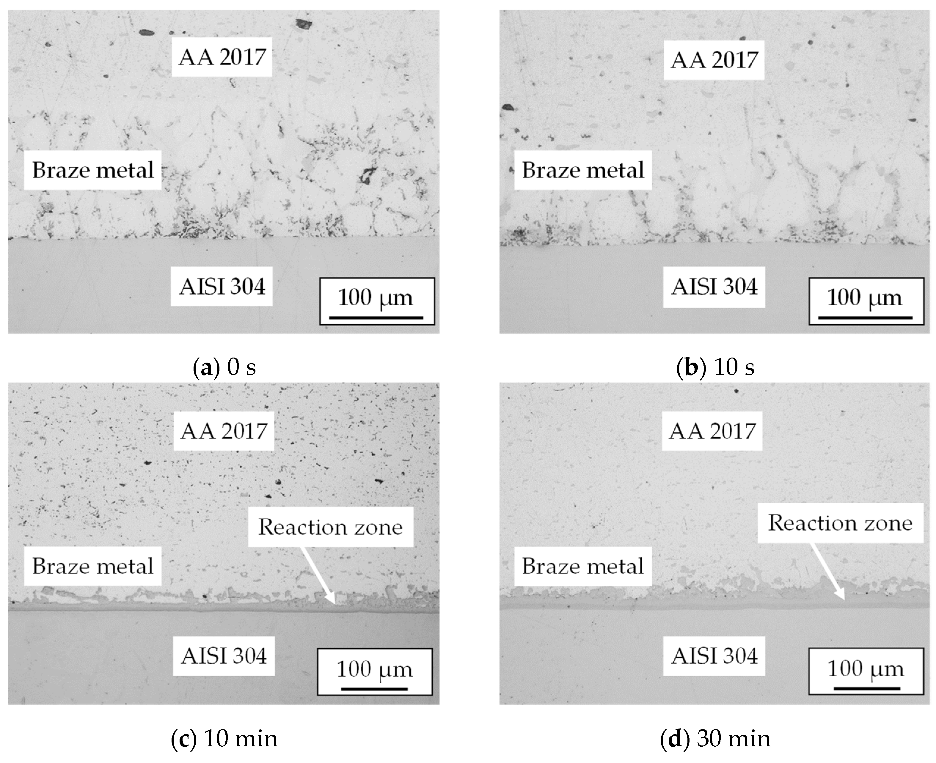
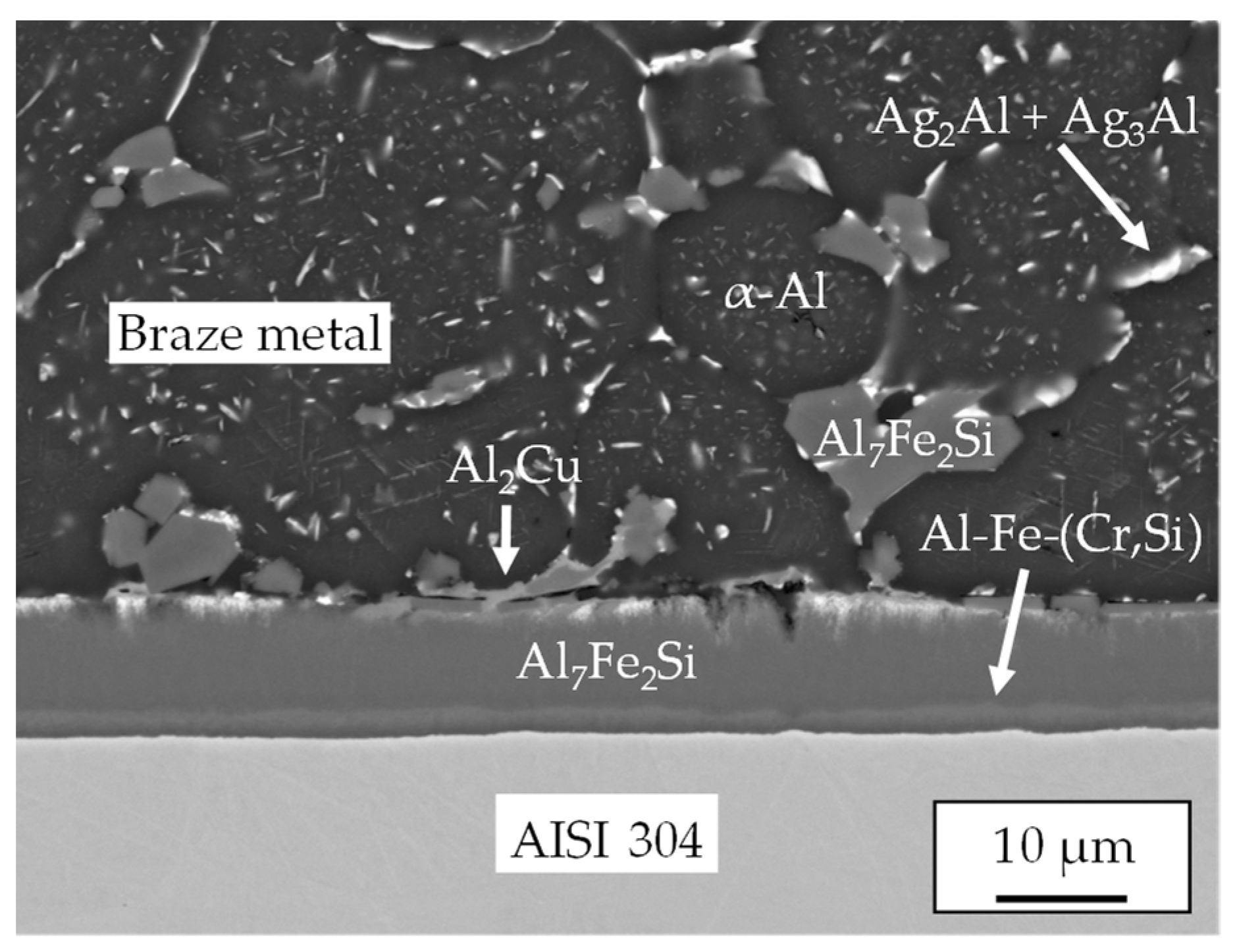
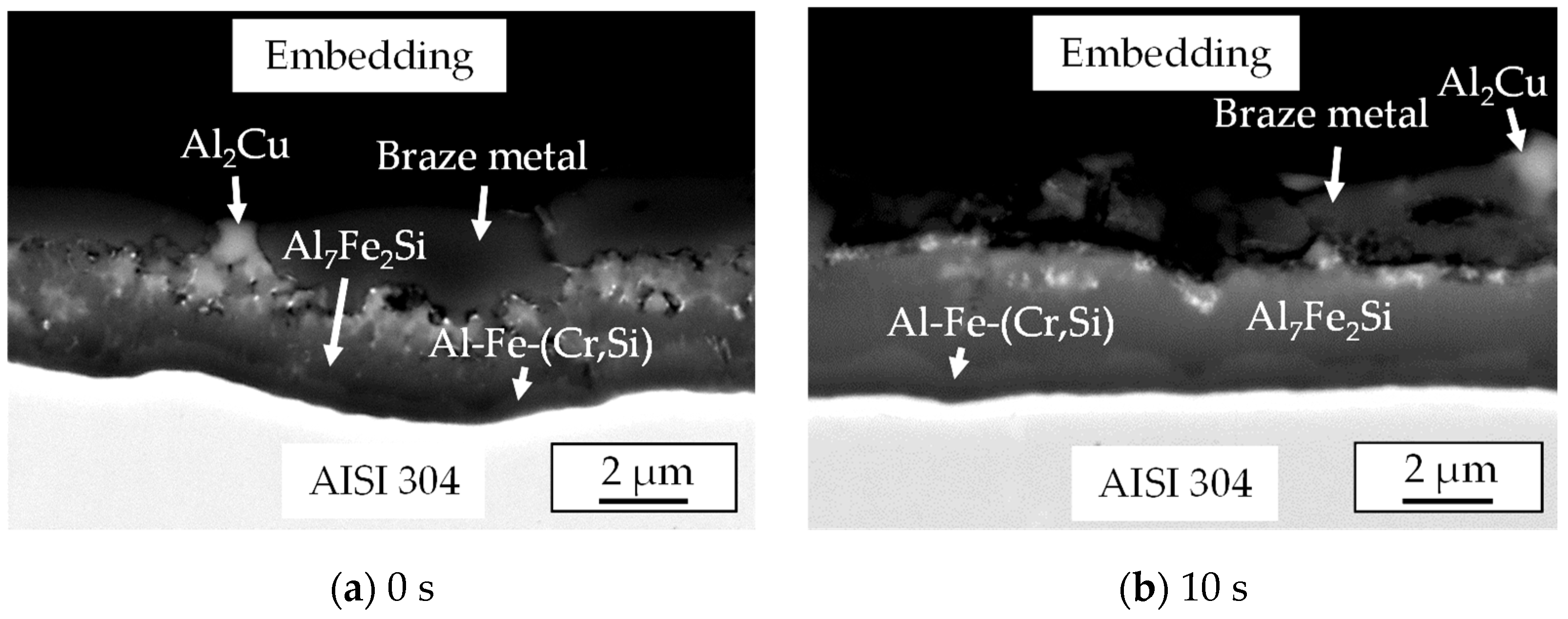
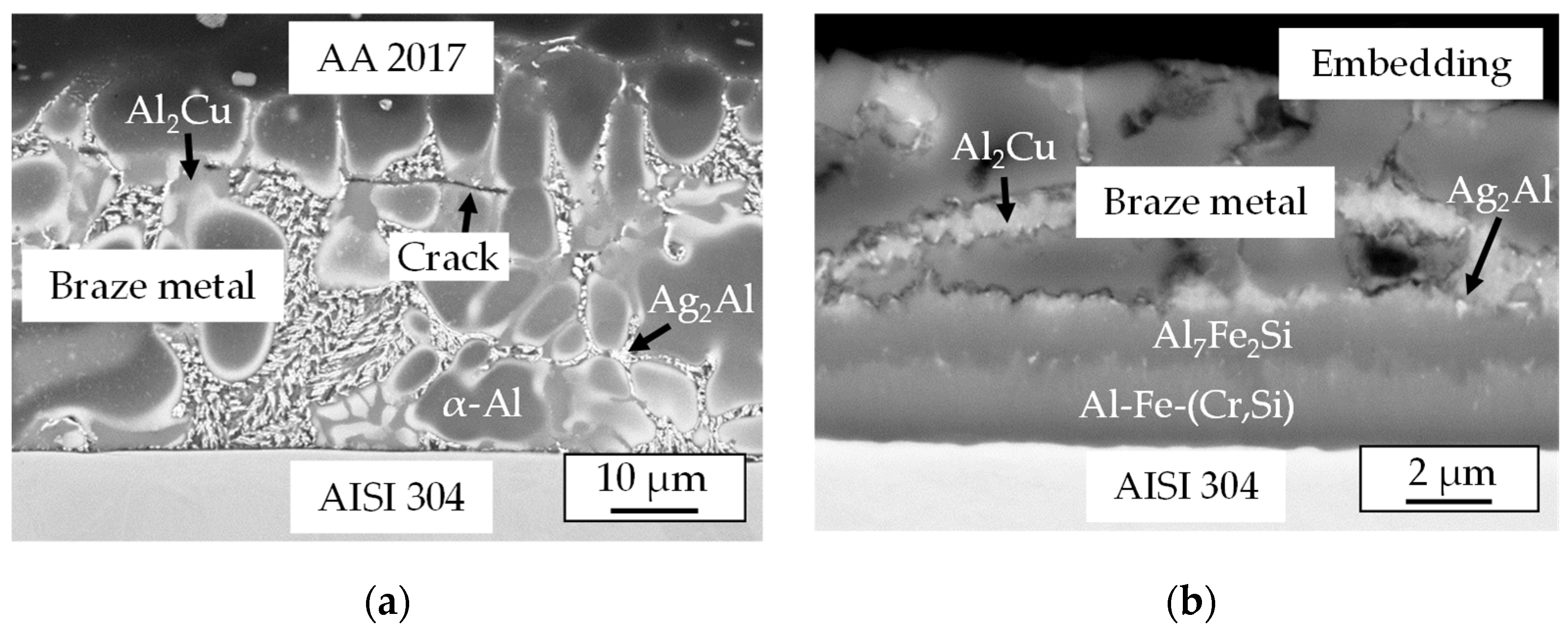
3.1. Microstructure of the Aluminum/Stainless Steel Brazed Joint

The microstructures of the brazed joints are presented in Figure 2. During the brazing process, the wetting between liquid filler metal and aluminum base material on the one hand and between liquid filler and stainless steel on the other hand was realized by a chemical reaction. On the aluminum base material side, a type of welded joint formed during the interaction of the aluminum-containing braze metal with the aluminum base material. The reaction zone between the braze metal and stainless steel was formed due the diffusion of Fe and Cr atoms from the stainless steel into the braze metal and their reaction with the atoms of chemical elements of the braze metal. In the case of the joints, produced via induction brazing, a very small thickness of the reaction zone between the braze metal and the stainless steel could be seen. Compared to these joints, the reaction zone of the vacuum-brazed joints grew more clearly with an increase in the holding time. Moreover, the vacuum-brazed joints showed good quality with a minimum number of pores, too.
To determine the chemical composition of the intermetallic layer at the interface to the stainless steel quantitatively via EDS analysis, high layer thickness was required. This could be achieved by increasing the holding time of the brazing process. Therefore, it was necessary to perform the EDS analysis on vacuum-brazed samples. For the joints brazed at 540 °C for 10 min, the thickness of the reaction zone was about 10 μm. These samples were used to measure the chemical composition of the microstructural constituents of the brazed joints via EDS. The analyses indicate that an α-Al solid solution with a low content of Ag (4 at.%) as well as Al2Cu, Ag2Al + Ag3Al, and Al7Fe2Si precipitates formed in the braze metal; Figure 3. Furthermore, it can be seen that the reaction zone consisted of two intermetallic layers: an Al7Fe2Si layer and an Al-Fe-(Cr,Si) layer with 4 at.% of Cr and 2 at.% of Si.

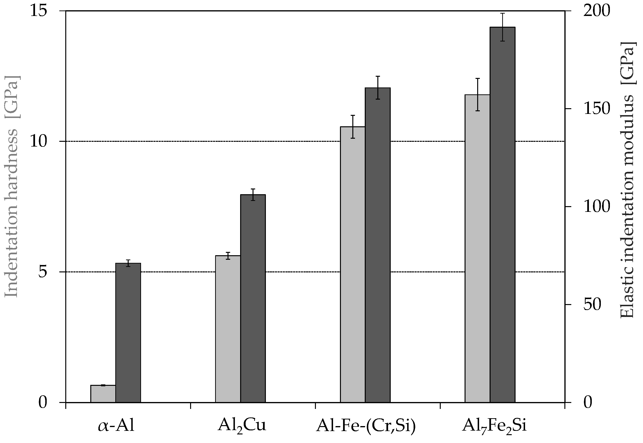
3.2. Nanoindentation

For the comparison of the indents’ size in various of microstructural constituents in the brazed joint, the indents in the Al solid solution in the braze metal and in Al7Fe2Si and Al-Fe-(Cr,Si) intermetallic layers at the interface to the stainless steel are presented in Figure 4. It can be seen that the indent produced in the Al solid solution (Figure 4a) showed a higher penetration depth and a bigger contact area in comparison to the indents set in the intermetallic layers (Figure 4b). This already shows that the intermetallic layers had a higher indentation hardness than the Al solid solution. In addition, the indents produced in the intermetallic layers showed a good position inside the intermetallic layers and an acceptable distance to the adjacent stainless steel and other microstructural constituents in the braze metal. The indentation hardness and the elastic indentation modulus of the Ag2Al and Ag3Al precipitates could not be measured due to their small size.
The results of the nanoindentation experiments are shown in Figure 5. In the diagram, it can be clearly seen that the Al7Fe2Si and Al-Fe-(Cr,Si) intermetallic layers had a significantly higher hardness than all other microstructural constituents in the braze metal. The indentation hardnesses of the Al7Fe2Si and Al-Fe-(Cr,Si) intermetallic layers were 11.8 GPa and 10.6 GPa, while the Al solid solution and the Al2Cu precipitates showed a hardness of 0.7 GPa and 5.6 GPa, respectively. These hardness values correspond to the literature data, which presented the indentation hardness and the elastic indentation moduli of these microstructural constituents [14,15]. The higher hardness of the Al7Fe2Si intermetallic layer can be explained by the presence of a higher content of silicon in this layer in comparison to the Al-Fe-(Cr,Si) intermetallic layer. Consequently, the high hardness of the intermetallic layers could have caused the crack initiation and crack propagation during the mechanical testing of the brazed joints.
In addition, the indentation moduli of the investigated microstructural constituents in the braze metal were determined. Obviously, the indentation modulus of the α-Al solid solution was lower than the measured values of the other microstructural constituents. The indentation modulus of the α-Al solid solution was 71.2 GPa, while the Al7Fe2Si and Al-Fe-(Cr,Si) intermetallic layers and Al2Cu precipitates had elastic indentation moduli of 183.7 GPa, 191.7 GPa, and 106.1 GPa, respectively. These measured values also correspond to the literature data mentioned above [14,15]. Moreover, the Al solid solution was more easily deformable than the other microstructural constituents in the braze metal. It was determined that the elastic indentation modulus of the Al solid solution was in the range of the moduli of aluminum alloys (60–78 GPa) [16]. The elastic indentation modulus measured via nanoindentation was comparable to the elastic modulus of the material [12].

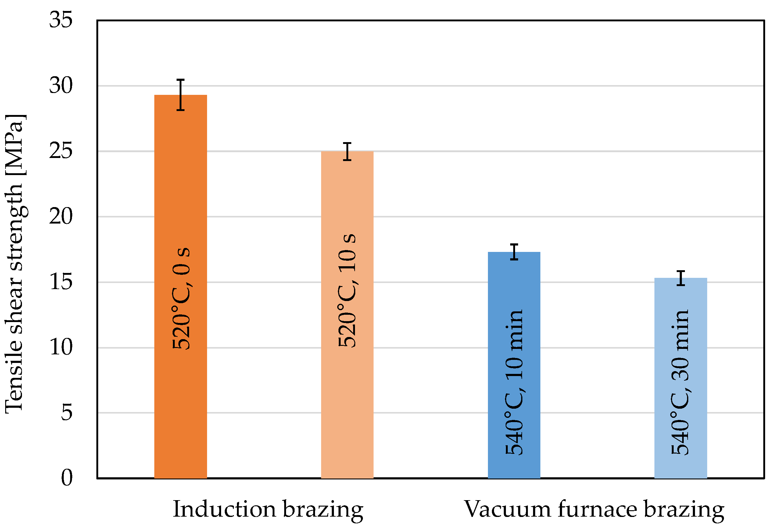
3.3. Tensile Shear Strength of the Brazed Joints

The results of the tensile shear tests of the investigated joints are presented in Figure 6. It can be clearly seen that the joints produced via induction brazing had higher strengths compared to the vacuum-brazed samples. Compared to all the tested joints, the samples brazed at 520 °C without holding time achieved the highest tensile shear strength of about 32 MPa. The strength values were significantly higher than the results of Grund et al. (20 MPa). Grund et al. reported stress-induced cracks at the interface to stainless steel, which occurred due to the local overheating of the liquid brazing filler and resulted in the formation of thick brittle Fe-Al intermetallic layers at the interface to the stainless steel [9]. A holding time of 10 s led to a maximum tensile shear strength of 26 MPa. The decrease in the strength values can also be explained by the increase in holding time or the growth of the Al7Fe2Si and Al-Fe-(Cr,Si) intermetallic layers in the reaction zone [17]. For the vacuum-brazed joints, a maximum tensile shear strength of 18 MPa was reached in samples brazed at 540 °C for 10 min. The decrease in tensile shear strength with prolonged holding time can be explained by the growth of the reaction zone. Moreover, the long holding time led to the strong diffusion of the elements of the braze metal into the aluminum base material. This resulted in the thickness reduction in the brazing gap, which could have led to a decrease in the tensile shear strength.
All tested samples were investigated using SEM. In Figure 7, the SEM images of the cross sections of the fracture surfaces are presented. It was found that different fracture mechanisms occurred in the investigated brazed joints. The samples produced via induction brazing failed in the braze metal near to the reaction zone, which was indicated by the residue of adhering braze metal (Figure 7a,b). In cross sections, it can be seen that the thickness of the reaction zone as well as the intermetallic layers increased with an increase in holding time. This caused the decrease in tensile shear strength values, but it did not affect the fracture mechanism. In contrast, the fracture of the tested samples produced via vacuum furnace brazing at 540 °C for 10 and 30 min occurred in the reaction zone, especially inside the Al7Fe2Si intermetallic layer (Figure 7c,d). This fracture mechanism can be explained by the high thickness of the existing intermetallic Al7Fe2Si layer (Figure 7c) and the formation and growth of the Al-Fe-(Cr,Si) intermetallic layer in the reaction zone (Figure 7d) [17]. In this case, it can be seen that the thickness of the intermetallic layers as well as the reaction zone of the vacuum-brazed joints increased more significantly with an increase in the holding time compared to joints produced via induction brazing. This caused lower joining strength values.
Because of the fact that joints produced via induction brazing show higher tensile shear strength values in comparison to the vacuum-brazed joints, the present work focused on the investigation of the fatigue behavior of these joints.

3.4. Fatigue Behavior of the Brazed Joints

The results of the fatigue tests on the inductively brazed joints are presented in Figure 8. It can be seen that the joints brazed without holding time reached a number of cycles of 5 × 10³ at the highest stress level σa = 13 MPa. At the lowest stress level, which corresponded to a stress amplitude of 4 MPa, the defined limited number of cycles Nlimit = 1 × 10⁷ was reached. In contrast, the joints brazed with a holding time of 10 s reached a number of cycles of 3 × 10³ at the highest stress level σa = 10.6 MPa. At the lowest stress level, the joints reached the defined limited number of cycles at a stress amplitude of 3.5 MPa. The low fatigue strength of these brazed joints could have been caused by the shear stress in the overlap geometries typical for brazed joints. Furthermore, the notch effect that inevitably occurred in the braze fillets and the resulting stress concentration had a significant influence on the achieved strength values. For these reasons, application-oriented test geometry was used in this work. Values obtained using this geometry can be transferred directly to real components, which makes it easier to use mixed joints in designs [18]. In addition, it can be seen that the holding time did not have a significant influence on the fatigue behavior of the brazed joints. For all stress levels, the joints brazed with a holding time of 10 s largely failed no faster than the joints brazed without holding time.
After that, the fatigue tested samples were investigated using SEM. The cross sections of the samples of the joints brazed at 520 °C without holding time are presented in Figure 9. First, an SEM investigation was carried out on the cross section of the “run out” fatigue-tested samples, which reached the defined limited number of cycle at a stress amplitude of 4 MPa. In Figure 9a, it can be clearly seen that the crack arises in the braze metal, especially in the eutectic constituents. This can be explained by residual stresses, which were caused by the high differences in hardness of the microstructural constituents of the braze metal [19]. During the fatigue test with a stress amplitude of 13 MPa, the tested joints failed at a number of cycles of about 5 × 10³. During the SEM investigation of these samples, it was found that the failure occurred in the braze metal; Figure 9b. In this case, the reaction zone had no significant influence on the crack initiation and crack propagation.
Analogously to the joints brazed at 520 °C without holding time, SEM investigations were carried out on the joints brazed at 520 °C for 10 s. The cross section of the “run out” fatigue-tested samples, which reached the defined limited number of cycles, and the cross section of the fatigue-tested samples, which failed at a number of cycles of 3 × 10³ at a stress amplitude of 10.6 MPa, are presented in Figure 10. The cross section of the “run out” sample also shows that the crack occurred in the braze metal, especially in the eutectic constituents; Figure 10a. For the sample which failed at a number of cycles of 3 × 10³ at a stress amplitude of 10.6 MPa, it was found that the fracture also occurred in the braze metal; Figure 10b. It can be summarized that the reaction zone did not significantly influence the fracture mechanism of the brazed joints.

4. Conclusions

High-strength aluminum alloy/stainless steel joints were successfully produced via induction brazing as well as vacuum furnace brazing using an Al-Ag-Cu-Si filler. The joints produced via induction brazing had a thin, uniform reaction zone to the stainless steel (~2 µm). In the joint produced via vacuum furnace brazing at 540 °C for 10 min, its thickness was about 10 μm. It consisted of two intermetallic layers: Al2Cu and Al7Fe2Si. The joints produced via induction brazing at 520 °C without holding time reached a maximum tensile shear strength of 32 MPa. For the joints brazed in a vacuum furnace at 540 °C for 10 min, the maximum tensile shear strength of 18 MPa was reached. For both brazing processes, the measured strength values decreased with an increase in the holding time. This could be explained by the increase in the thickness of the reaction zone as well as the intermetallic layers. The fractographic investigations showed that the fracture occurred at the interface between the braze metal and the reaction zone to the stainless steel for all the tested samples. In the case of the samples produced via induction brazing, the fracture occurred in the braze metal close to the reaction zone. This could be explained by internal stress caused by the high differences in the hardness of the microstructural constituents of the reaction zone as well as the increase in its thickness. The nanoindentation measurements showed that the Al7Fe2Si and Al-Fe-(Cr,Si) intermetallic layers had the indentation hardness of 11.8 and 10.6 GPa, while the Al solid solution and the Al2Cu precipitates showed hardness of 0.7 GPa and 5.6 GPa, respectively. For the samples brazed in the vacuum furnace, the failure arose inside the Al7Fe2Si intermetallic layer. This was caused by the high thickness of the Al7Fe2Si and Al-Fe-(Cr,Si) intermetallic layers. It can be summarized that the formation and growth mechanisms of these layers had a significant influence on the tensile shear strength of these brazed joints. The results of the fatigue tests show that the joints brazed without holding time achieved the defined limited number of cycles of 1 × 10⁷ at a stress amplitude of 4 MPa. The joints brazed with a holding time of 10 s did not fail any significantly faster than the joints brazed without holding time. All the fatigue-tested samples failed in the braze metal, especially in the eutectic constituents. Consequently, the reaction zone did not significantly influence the fracture mechanism of the high-strength aluminum alloy/stainless steel brazed joints during cyclic loading.

Author Contributions

Conceptualization, V.F.; methodology, V.F., T.U., and G.W.; formal analysis, V.F.; investigation, V.F.; resources, G.W.; writing—original draft preparation, V.F.; writing—review and editing, V.F., T.U., and G.W.; visualization, V.F.; supervision, T.U. and G.W.; funding acquisition, V.F. All authors have read and agreed to the published version of the manuscript.

Funding

This research was funded by Bundesministerium für Wirtschaft und Klimaschutz and industrielle Gemeinschaftsforschung, project number 21.016 BR. The publication of this article was funded by Chemnitz University of Technology and by the Deutsche Forschungsgemeinschaft (DFG, German Research Foundation)—491193532.

Institutional Review Board Statement

Not applicable.

Informed Consent Statement

Not applicable.

Data Availability Statement

Not applicable.

Conflicts of Interest

The authors declare no conflict of interest.

References

  1. Martinsen, K.; Hu, S.J.; Carlson, B.E. Joining of dissimilar materials. CIRP Ann. 2015, 64, 679–699. [Google Scholar] [CrossRef] [Green Version]
  2. Elßner, M.; Weis, S.; Wagner, G. Joining of Aluminum Matrix Composites and Stainless Steel by Arc Brazing. Mater. Sci. Forum 2015, 825–826, 393–400. [Google Scholar] [CrossRef]
  3. Witusiewicz, V.T.; Hecht, U.; Fries, S.G.; Rex, S. The Ag–Al–Cu system: II. A thermodynamic evaluation of the ternary system. J. Alloy. Compd. 2005, 387, 217–227. [Google Scholar] [CrossRef]
  4. Böyük, U.; Marasli, N.; Kaya, H.; Cadirli, E.; Keslioglu, K. Directional solidification of Al–Cu–Ag alloy. Appl. Phys. A 2009, 95, 923–932. [Google Scholar] [CrossRef]
  5. Genau, A.; Ratke, L. Morphological characterization of the Al –Ag–Cu ternary eutectic. Int. J. Mater. Res. 2012, 103, 469–475. [Google Scholar] [CrossRef]
  6. Dennstedt, A.; Choudhury, A.; Ratke, L.; Nestler, B. Microstructures in a ternary eutectic alloy: Devising metrics based on neighbourhood relationships. IOP Conf. Ser. Mater. Sci. Eng. 2016, 117, 012025. [Google Scholar] [CrossRef]
  7. Elßner, M.; Weis, S.; Wagner, G.; Grund, T. Joining of material compounds of aluminium matrix composites (AMC) by arc brazing using Al-Ag-Cu system filler alloy. Weld. World 2017, 61, 405–411. [Google Scholar] [CrossRef]
  8. Grund, T.; Gester, A.; Wagner, G.; Habisch, S.; Mayr, P. Arc Brazing of Aluminium, Aluminium Matrix Composites and Stainless Steel in Dissimilar Joints. Metals 2018, 8, 166. [Google Scholar] [CrossRef] [Green Version]
  9. Fedorov, V.; Uhlig, T.; Podlesak, H.; Wagner, G. Microstructural Study of Al-Ag-Cu-Si Filler Metal for Brazing High-Strength Aluminum Alloys to Stainless Steel. Metals 2020, 10, 1563. [Google Scholar] [CrossRef]
  10. Srinivas, V.; Singh, A.K.; Reddy, M. Vacuum brazing of dissimilar tubular component of AA2219 and AISI 304 by a low melting Al-18Ag-20Cu-5Si-0.2 Zn braze alloy. J. Mater. Process. Technol. 2018, 252, 1–12. [Google Scholar]
  11. Winiowski, A. Structural and mechanical properties of brazed joints of stainless steel and aluminium. Arch. Metall. Mater. 2009, 54, 523–533. [Google Scholar]
  12. ISO 14577-1:2015; Metallic Materials—Instrumented Indentation Test for Hardness and Materials Parameters—Part 1: Test method. International Organization for Standardization: Geneva, Switzerland, 2015. Available online: https://www.iso.org/standard/56626.html (accessed on 1 September 2020).
  13. Oliver, W.C.; Pharr, G.M. An improved technique for determining hardness and elastic modulus using load and displacement sensing indentation experiments. J. Mater. Res. 1992, 7, 1564–1583. [Google Scholar] [CrossRef]
  14. Ivannikov, A.; Fedorov, V.; Abramov, A.; Penyaz, M.; Bachurina, D.; Uhlig, T.; Suchkov, A.; Wagner, G.; Morokhov, P.; Sevryukov, O. Development of Rapidly-Quenched Al-Ge-Si Filler Alloys for the Joining of Stainless Steel AISI 304 and Aluminum Alloy AA6082. Metals 2021, 11, 1926. [Google Scholar] [CrossRef]
  15. Lan, X.; Li, K.; Wang, J.; Lu, Q.; Yang, T.; Xiao, Y.; Du, Y. Preparation of ultra-large intermetallic particles in al alloys for ac-curate determination of their mechanical properties. Intermetallics 2023, 152, 107771. [Google Scholar] [CrossRef]
  16. Kammer, C. Aluminium Taschenbuch Band 1: Grundlagen und Werkstoffe; Aluminium-Verlag: Düsseldorf, Germany, 2009. [Google Scholar]
  17. Fedorov, V.; Uhlig, T.; Wagner, G. Influence of the Thickness of the Reaction Zone in Aluminum/Stainless Steel Brazed Joints on the Mechanical Properties. Metals 2021, 11, 217. [Google Scholar] [CrossRef]
  18. Jöckel, A.; Baumgartner, J.; Tillmann, W.; Bültena, J.; Bobzin, K.; Heinemann, H.; Hebing, J.; Erck, M. Influence of brazing process and gap size on the fatigue strength of shear and peel specimen. Weld. World 2022, 66, 1941–1955. [Google Scholar] [CrossRef]
  19. Fedorov, V.; Uhlig, T.; Wagner, G.; Langohr, A.; Holländer, U. Influence of nitrogen in brazing atmospheres on the hardness of the microstructural constituents of brazed stainless steel joints. IOP Conf. Ser. Mater. Sci. Eng. 2019, 480, 012034. [Google Scholar] [CrossRef]
Figure 1. Sample geometry of the produced joints. Values are given in mm.
Metals 13 00242 g001
Figure 2. Light microscopic images of the joints, produced via induction brazing (a,b) and vacuum furnace brazing (c,d).
Metals 13 00242 g002
Figure 3. SEM image of the microstructure of the joint brazed at 540 °C for 10 min.
Metals 13 00242 g003
Figure 4. SEM (BSE) images: (a) indent in the Al solid solution; (b) indents in the intermetallic layers Al7Fe2Si and Al-Fe-(Cr,Si).
Metals 13 00242 g004
Figure 5. Results of nanoindentation: hardness (light gray) and indentation modulus (dark gray) of the microstructural constituents in the braze metal as well as in the reaction zone.
Metals 13 00242 g005
Figure 6. Tensile shear strength of brazed joints.
Metals 13 00242 g006
Figure 7. SEM images of the cross sections of the fracture surfaces of the tested samples produced via induction brazing (a,b) and vacuum furnace brazing (c,d).
Metals 13 00242 g007aMetals 13 00242 g007b
Figure 8. Fatigue behavior of the joints produced via induction brazing at 520 °C and holding times of 0 s and 10 s.
Metals 13 00242 g008
Figure 9. SEM images of the cross sections of the tested joints, produced via induction brazing at 520 °C for 0 s: (a) the “run out” fatigue-tested sample (σa = 4 MPa, Nlimit = 1 × 10⁷), (b) the fracture surface of the fatigue-tested sample (σa = 13 MPa, N = 5 × 10³).
Metals 13 00242 g009
Figure 10. SEM images of the cross sections of the tested joints produced via induction brazing at 520 °C for 10 s: (a) the “run out” fatigue-tested sample (σa = 3.5 MPa, Nlimit = 1 × 10⁷) and (b) the fracture surface of the fatigue-tested sample (σa = 10.6 MPa, N = 3 × 10³).
Metals 13 00242 g010
Table 1. Chemical compositions of the used materials.
AlloyAlloy Composition (wt.%)
AlFeAgCuSiMnMg
AA 2017bal.0.7-40.810.8
AISI 304-bal.--0.41.4-
Al-Ag-Cu-Si39.4-39.419.71.5--
Table 2. Temperature–time regimes.
ProcessTemperature (°C)Holding Time (s)
Induction brazing520010
Vacuum furnace brazing5406001800
Disclaimer/Publisher’s Note: The statements, opinions and data contained in all publications are solely those of the individual author(s) and contributor(s) and not of MDPI and/or the editor(s). MDPI and/or the editor(s) disclaim responsibility for any injury to people or property resulting from any ideas, methods, instructions or products referred to in the content.

