
Influences of Strain on the Microstructure and Mechanical Properties of High-Carbon Steel


Abstract
:
1. Introduction
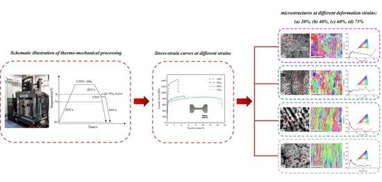
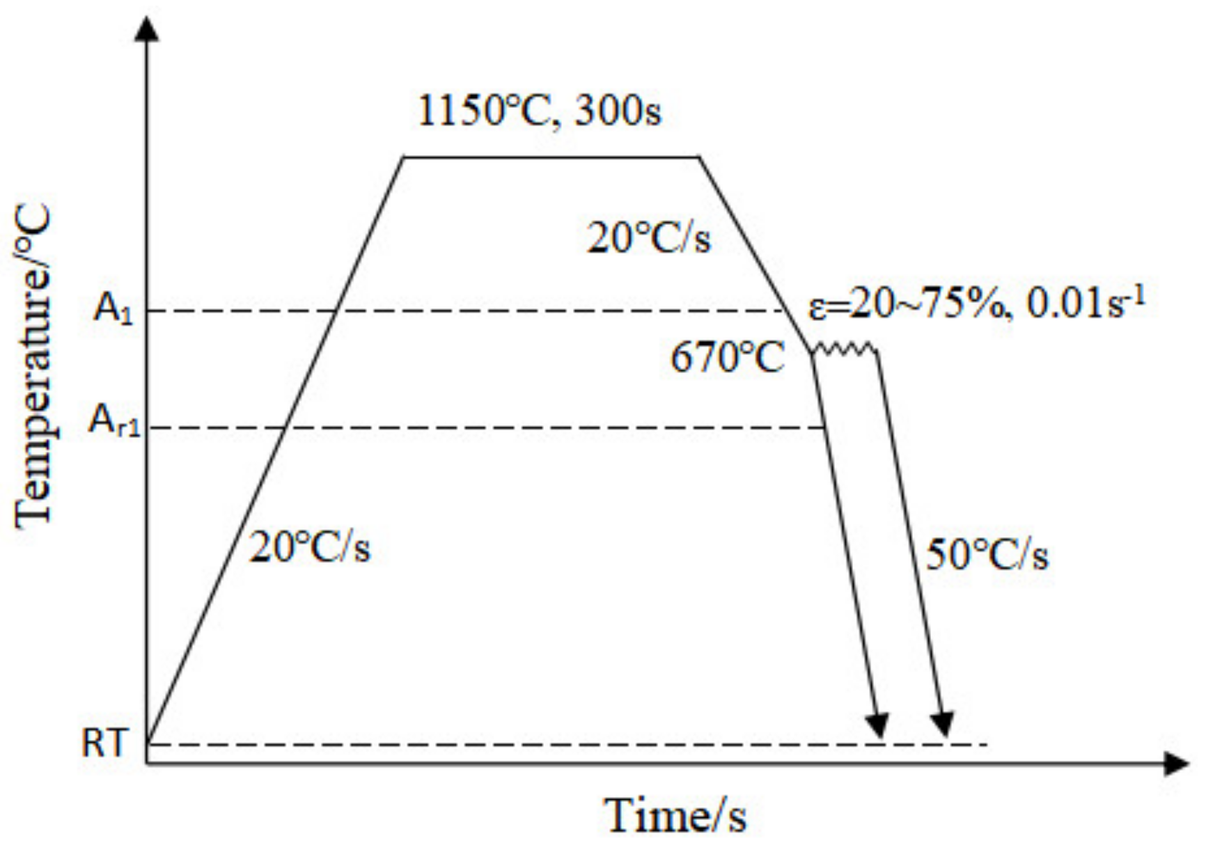
2. Materials and Methods
3. Results
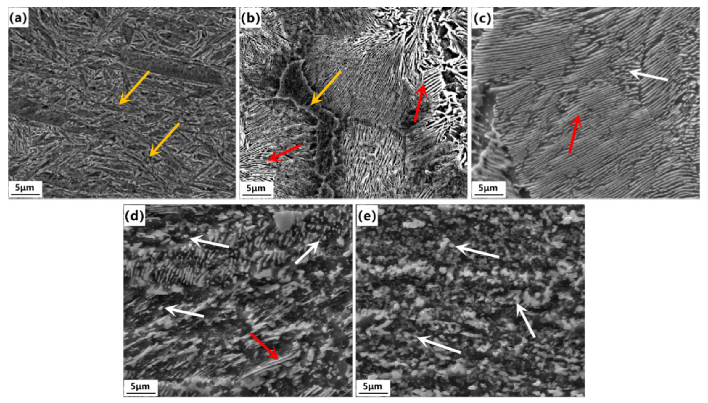
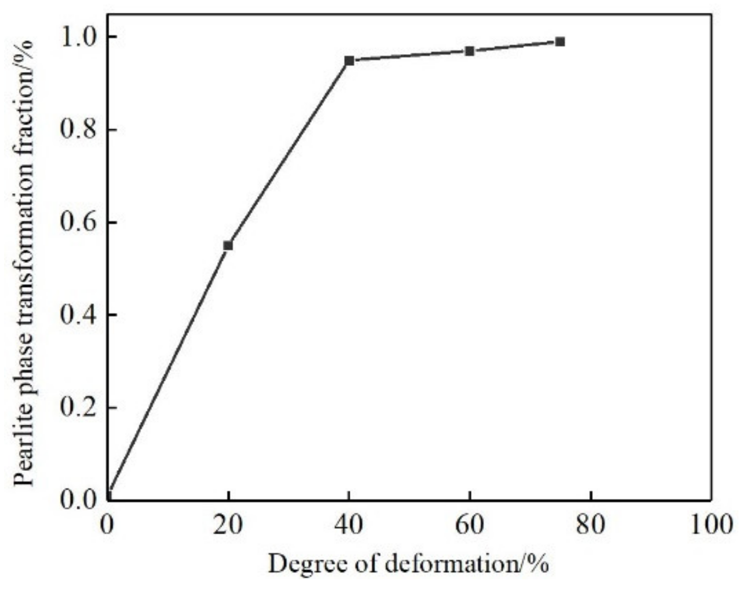
3.1. Microstructure
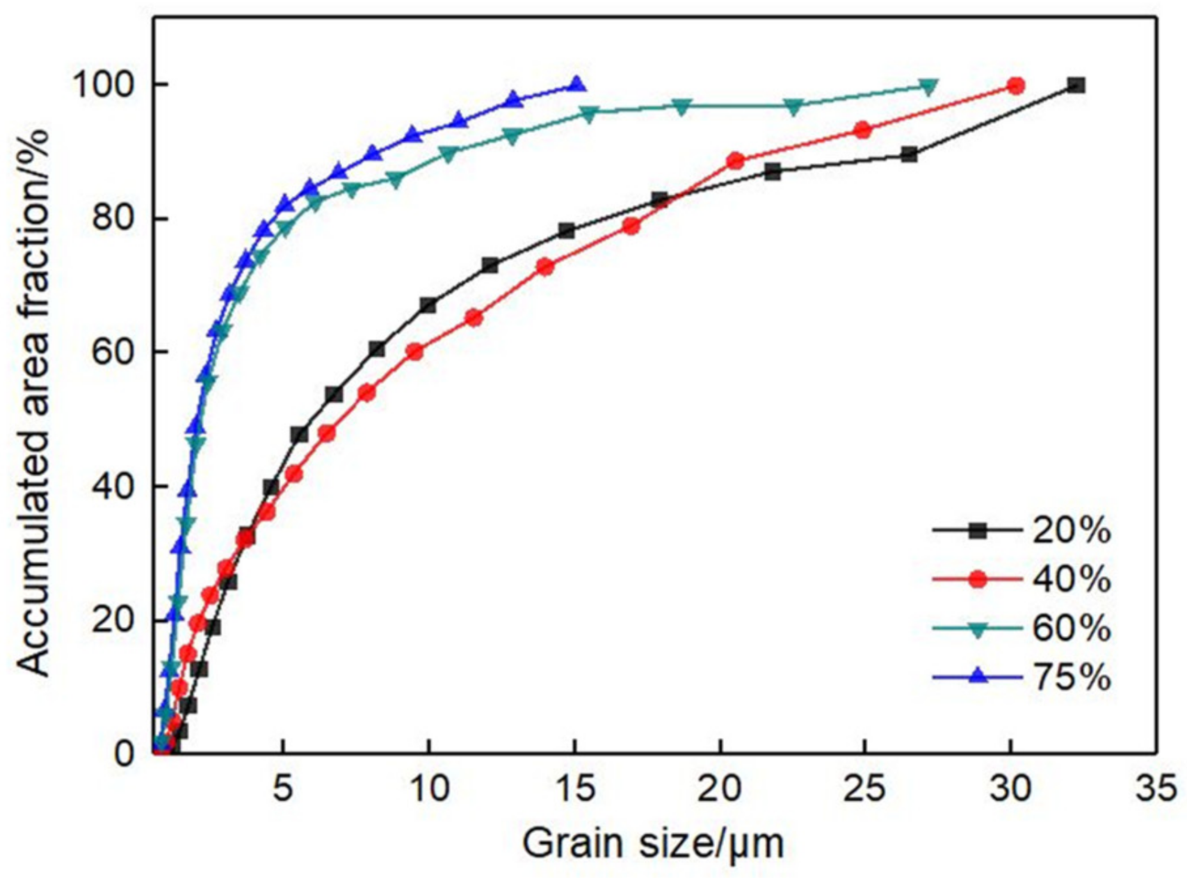
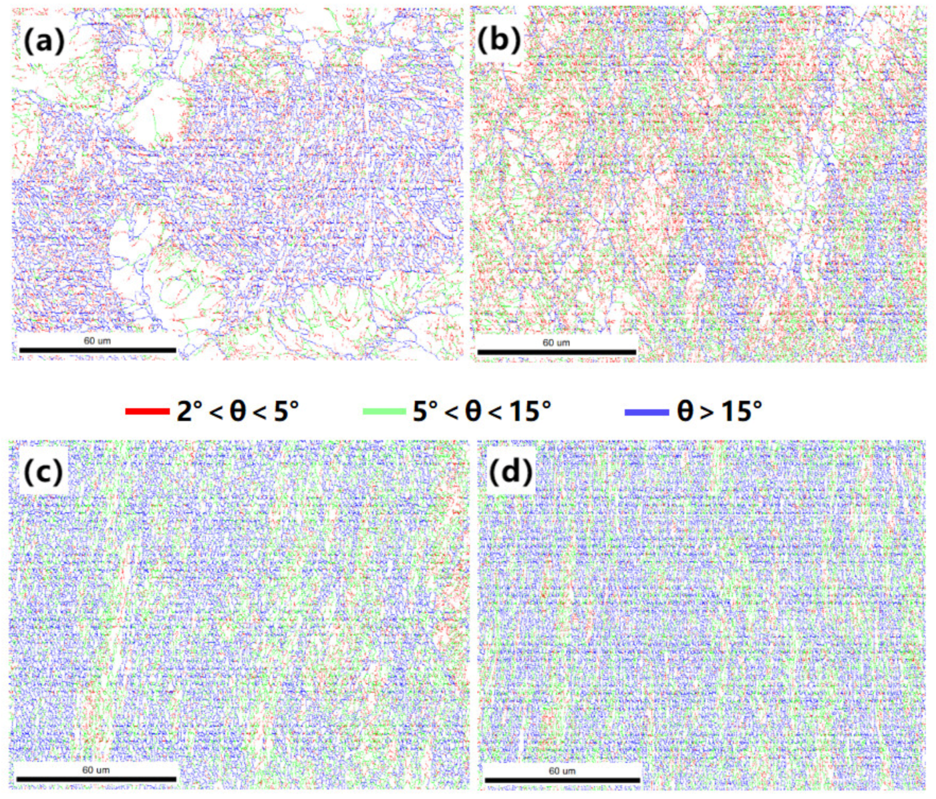
3.2. Grain Size and Orientation
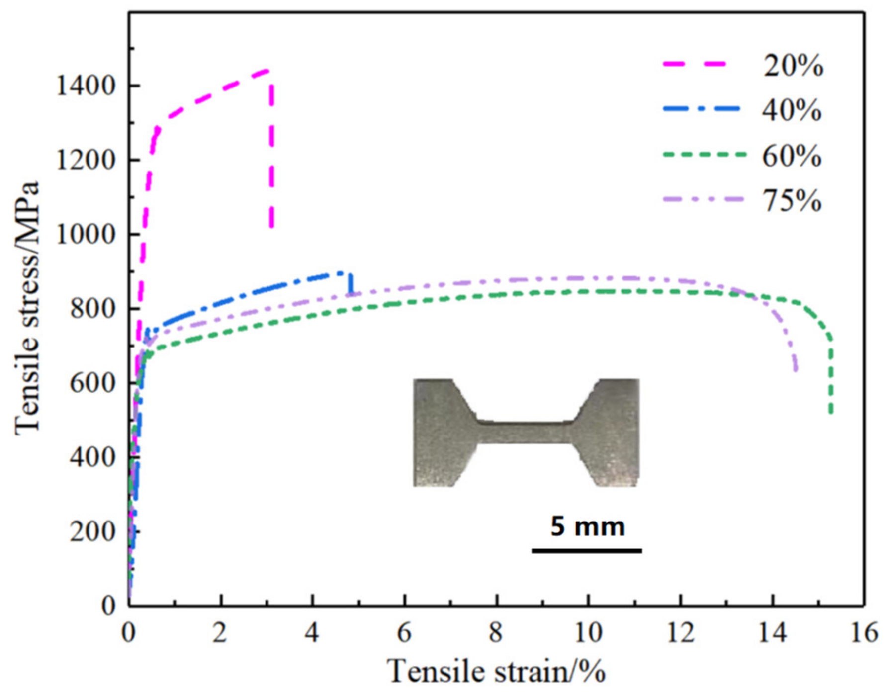
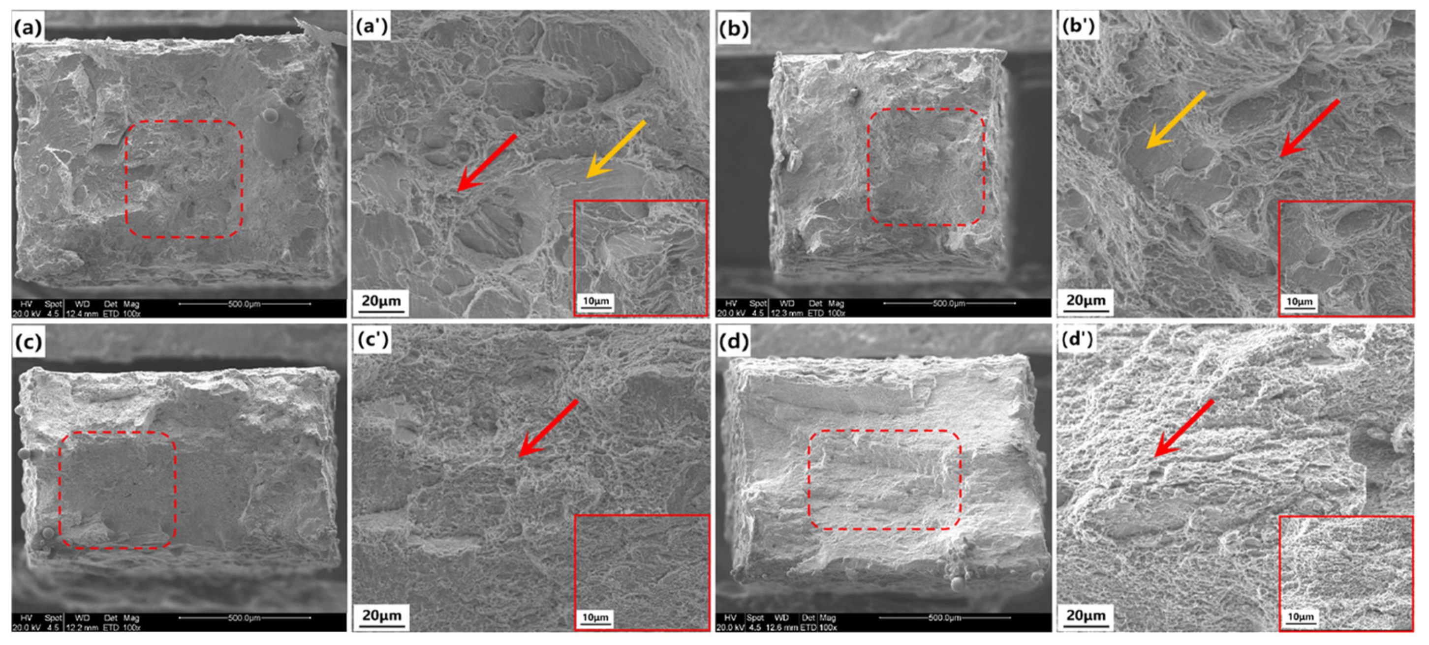
3.3. Mechanical Properties and Fracture Surface
4. Discussion
5. Conclusions
Author Contributions
Funding
Institutional Review Board Statement
Informed Consent Statement
Data Availability Statement
Conflicts of Interest
References
- Xu, P.W.; Liang, Y.; Li, J.; Meng, C. Further improvement in ductility induced by the refined hierarchical structures of pearlite. Mater. Sci. Eng. A 2019, 745, 176–184. [Google Scholar] [CrossRef]
- Sun, J.J.; Lian, F.L.; Liu, H.J.; Jiang, T.; Guo, S.W.; Du, L.X.; Liu, Y.N. Microstructure of warm rolling and pearlitic transformation of ultrafine-grained GCr15 steel. Mater. Charact. 2014, 95, 291–298. [Google Scholar] [CrossRef]
- Wang, M.M.; Zhang, F.C.; Yang, Z.N. Effects of high-temperature deformation and cooling process on the microstructure and mechanical properties of an ultrahigh-strength pearlite steel. Mater. Des. 2017, 114, 102–110. [Google Scholar] [CrossRef]
- Song, R.; Ponge, D.; Raabe, D.; Speer, J.G.; Matlock, D.K. Overview of processing, microstructure and mechanical properties of ultrafine grained bcc steels. Mater. Sci. Eng. A 2006, 441, 1–17. [Google Scholar] [CrossRef]
- Tikhonova, M.; Belyakov, A.; Kaibyshev, R. Strain-induced grain evolution in an austenitic stainless steel under warm multiple forging. Mater. Sci. Eng. A 2013, 564, 413–422. [Google Scholar] [CrossRef]
- Doherty, R.D.; Szpunar, J.A. Kinetics of sub-grain coalescence-A reconsideration of the theory. Acta Mater. 1984, 32, 1789–1798. [Google Scholar] [CrossRef]
- Yang, Z.; Yang, R. Formation of ultra-fine grain structure of plain low carbon steel through deformation induced ferrite transformation. ISIJ Int. 2003, 43, 761–766. [Google Scholar] [CrossRef]
- Wu, T.; Wang, M.Z.; Gao, Y.W.; Li, X.P.; Zhao, Y.C.; Zou, Q. Effects of plastic warm deformation on cementite spheroidization of a eutectoid steel. J. Iron Steel Res. Int. 2012, 19, 60–66. [Google Scholar] [CrossRef]
- Gavriljuk, V.G. Decomposition of cementite in pearlitic steel due to plastic deformation. Mater. Sci. Eng. A 2003, 345, 81–89. [Google Scholar] [CrossRef]
- Mishra, K.; Khiratkar, V.N.; Singh, A. Change of deformation mechanism through nano-structuring of pearlite: An in-situ study. Mater. Charact. 2020, 167, 110487. [Google Scholar] [CrossRef]
- Zhang, S.L.; Sun, X.J.; Dong, H. Effect of deformation on the evolution of spheroidization for the ultra high carbon steel. Mater. Sci. Eng. A 2006, 432, 324–332. [Google Scholar] [CrossRef]
- Zhang, X.; Godfrey, A.; Huang, X.; Hansen, N.; Liu, Q. Microstructure and strengthening mechanisms in cold-drawn pearlitic steel wire. Acta Mater. 2011, 59, 422–3430. [Google Scholar] [CrossRef]
- Kapp, M.W.; Hohenwarter, A.; Wurster, S.; Yang, B.; Pippan, R. Anisotropic deformation characteristics of an ultrafine and nanolamellar pearlitic steel. Acta Mater. 2016, 106, 239–248. [Google Scholar] [CrossRef]
- Bae, C.M.; Lee, C.S.; Nam, W.J. Effect of carbon content on mechanical properties of fully pearlitic steels. Mater. Sci. Technol. 2002, 18, 1317–1321. [Google Scholar] [CrossRef]
- Offerman, S.E.; Van Wilderen, L.J.G.W.; Van Dijk, N.H.; Sietsma, J.; Rekveldt, M.T.; Van der Zwaag, S. In-situ study of pearlite nucleation and growth during isothermal austenite decomposition in nearly eutectoid steel. Acta Mater. 2003, 51, 3927. [Google Scholar] [CrossRef]
- Mishra, K.; Singh, A. Effect of interlamellar spacing on fracture toughness of nano-structured pearlite. Mater. Sci. Eng. A 2017, 706, 22–26. [Google Scholar] [CrossRef]
- Rastegari, H.; Kermanpur, A.; Najafifizadeh, A. Effect of initial microstructure on the work hardening behavior of plain eutectoid steel. Mater. Sci. Eng. A 2015, 632, 103–109. [Google Scholar] [CrossRef]
- Tsuzaki, K.; Sato, E.; Furimoto, S. Formation of an (α+θ) microduplex structure without thermomechanical processing in superplastic ultrahigh carbon steels. Scripta Mater. 1999, 40, 675–681. [Google Scholar] [CrossRef]
- Miyamoto, G.; Karube, Y.; Furuhara, T. Formation of grain boundary ferrite in eutectoid and hypereutectoid pearlitic steels. Acta Mater. 2016, 103, 370–381. [Google Scholar] [CrossRef]
- Storojeva, L.; Ponge, D.; Kaspar, R.; Raabe, D. Development of microstructure and texture of medium carbon steel during heavy warm deformation. Acta Mater. 2004, 52, 2209–2220. [Google Scholar] [CrossRef] [Green Version]
- Zhou, X.L.; Zhou, R.; Zhang, P.X.; Jiang, Y.H.; Li, Z.; Zhao, H. Magnetic field induced pearlite transformation in Fe-0.47C-2.31Si-3.15Mn steel above the eutectoid temperature. Mater. Sci. Eng. A 2009, 525, 42–47. [Google Scholar] [CrossRef]
- Mishra, K.; Khiratkar, V.N.; Singh, A. Improvement of sub-critical fatigue crack growth life by nano-structuring of pearlite. Int. J. Fatigue 2019, 122, 84–92. [Google Scholar] [CrossRef]
- Khiratkar, V.N.; Mishra, K.; Srinivasulu, P.; Singh, A. Effect of inter-lamellar spacing and test temperature on the charpy impact energy of extremely fine pearlite. Mater. Sci. Eng. A 2019, 754, 622–627. [Google Scholar] [CrossRef]
- Zhang, Y.D.; Esling, C.; Lecomte, J.S.; He, C.S.; Zhao, X.; Zuo, L. Grain boundary characteristics and texture formation in a medium carbon steel during its austenitic decomposition in a high magnetic field. Acta Mater. 2005, 53, 5213–5221. [Google Scholar] [CrossRef]
- Elwazri, A.M.; Wanjara, P.; Yue, S. Empirical modelling of the isothermal transformation of pearlite in hypereutectoid steel. Mater. Sci. Technol. 2006, 22, 542–546. [Google Scholar] [CrossRef]
- Takahama, Y.; Santofimia, M.J.; Mecozzi, M.G.; Zhao, L.; Sietsma, J. Phase field simulation of the carbon redistribution during the quenching and partitioning process in a low-carbon steel. Acta Mater. 2012, 60, 2916–2926. [Google Scholar] [CrossRef]
- Saeidi, N.; Ashrafifizadeh, F.; Niroumand, B.; Barlat, F. EBSD study of micromechanisms involved in high deformation ability of DP steels. Mater. Des. 2015, 87, 130–137. [Google Scholar] [CrossRef]
- Porter, D.A.; Easterling, K.E.; Smith, G.D.W. Dynamic studies of the tensile deformation and fracture of pearlite. Acta Metall. 1978, 26, 1405–1422. [Google Scholar] [CrossRef]
- Zhou, S.; Zuo, Y.; Li, Z.; Wang, X.; Yong, Q. Microstructural analysis on cleavage fracture in pearlitic steels. Mater. Charact. 2016, 119, 110–113. [Google Scholar] [CrossRef]
- Moon, J.; Jeong, H.; Lee, J.; Lee, C. Particle coarsening kinetics considering critical particle size in the presence of multiple particles in the heat-affected zone of a weld. Mater. Sci. Eng. A 2008, 483, 633–636. [Google Scholar] [CrossRef]
- Maazi, N.; Rouag, N. Consideration of Zener drag effect by introducing a limiting radius for neighbourhood in grain growth simulation. J. Cryst. Growth 2002, 243, 361–369. [Google Scholar] [CrossRef]
- Momeni, A.; Dehghani, K. Microstructural evolution and flow analysis during hot working of a Fe-Ni-Cr superaustenitic stainless steel. Metall. Mater. Trans. A Phys. Metall. Mater. Sci. 2011, 42, 1925–1932. [Google Scholar] [CrossRef]
- Thompson, S.W.; Howell, P.R. On the early stages of pearl1tic formation inhypoeutectoid steels. Scr. Metall. 1988, 22, 1775–1778. [Google Scholar] [CrossRef]
- Zhao, J.; Wang, T.S.; Lv, B.; Zhang, F.C. Microstructures and mechanical properties of a modified high-C-Cr bearing steel with nano-scaled bainite. Mater. Sci. Eng. A 2015, 628, 327–331. [Google Scholar] [CrossRef]
- Prasad, C.; Bhuyan, P.; Kaithwas, C.; Saha, R.; Mandal, S. Microstructure engineering by dispersing nano-spheroid cementite in ultrafine-grained ferrite and its implications on strength-ductility relationship in high carbon steel. Mater. Des. 2018, 139, 324–335. [Google Scholar] [CrossRef]


| C | Si | Mn | P | S | N | Fe |
|---|---|---|---|---|---|---|
| 0.81 | 0.22 | 0.31 | 0.011 | 0.003 | 0.004 | Bal. |
| Strain (%) | 20 | 40 | 60 | 75 |
|---|---|---|---|---|
| Yield stress (MPa) | 1297 ± 13 | 734 ± 8 | 683 ± 15 | 728 ± 6 |
| Tensile stress (MPa) | 1443 ± 11 | 898 ± 13 | 802 ± 7 | 883 ± 9 |
| Elongation (%) | 3.1 ± 0.3 | 4.8 ± 0.2 | 15.3 ± 0.5 | 14.5 ± 0.7 |
Publisher’s Note: MDPI stays neutral with regard to jurisdictional claims in published maps and institutional affiliations. |
© 2022 by the authors. Licensee MDPI, Basel, Switzerland. This article is an open access article distributed under the terms and conditions of the Creative Commons Attribution (CC BY) license (https://creativecommons.org/licenses/by/4.0/).
Share and Cite
Cai, Z.; Gan, X.; Li, Y.; Liu, S.; Bao, S.; Xu, G. Influences of Strain on the Microstructure and Mechanical Properties of High-Carbon Steel. Metals 2022, 12, 1518. https://doi.org/10.3390/met12091518
Cai Z, Gan X, Li Y, Liu S, Bao S, Xu G. Influences of Strain on the Microstructure and Mechanical Properties of High-Carbon Steel. Metals. 2022; 12(9):1518. https://doi.org/10.3390/met12091518
Chicago/Turabian StyleCai, Zhen, Xiaolong Gan, Yanqi Li, Sheng Liu, Siqian Bao, and Guang Xu. 2022. "Influences of Strain on the Microstructure and Mechanical Properties of High-Carbon Steel" Metals 12, no. 9: 1518. https://doi.org/10.3390/met12091518
APA StyleCai, Z., Gan, X., Li, Y., Liu, S., Bao, S., & Xu, G. (2022). Influences of Strain on the Microstructure and Mechanical Properties of High-Carbon Steel. Metals, 12(9), 1518. https://doi.org/10.3390/met12091518