

The Influence of Heat Treatment on the Microstructure, Surface Roughness and Shear Tensile Strength of AISI 304 Clinch Joints

Abstract
1. Introduction
2. Material and Methods
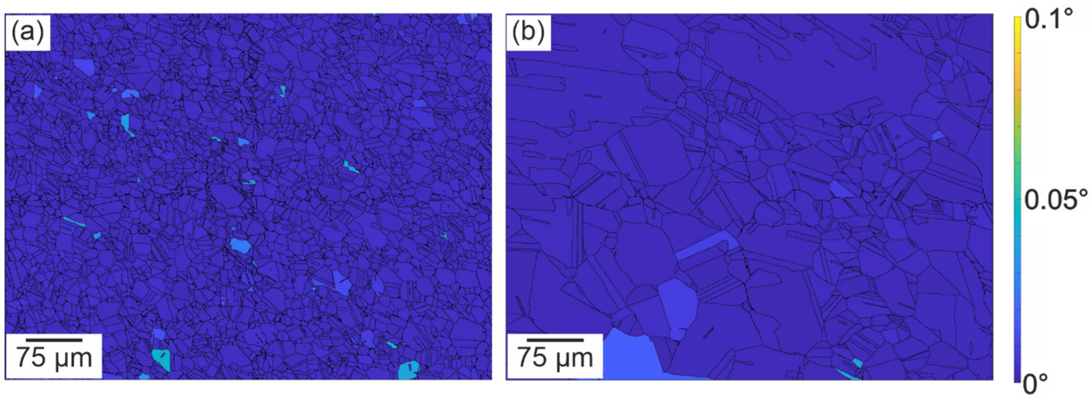
2.1. Characterization of the Initial Base Material in the As-Received and Heat-Treated Conditions
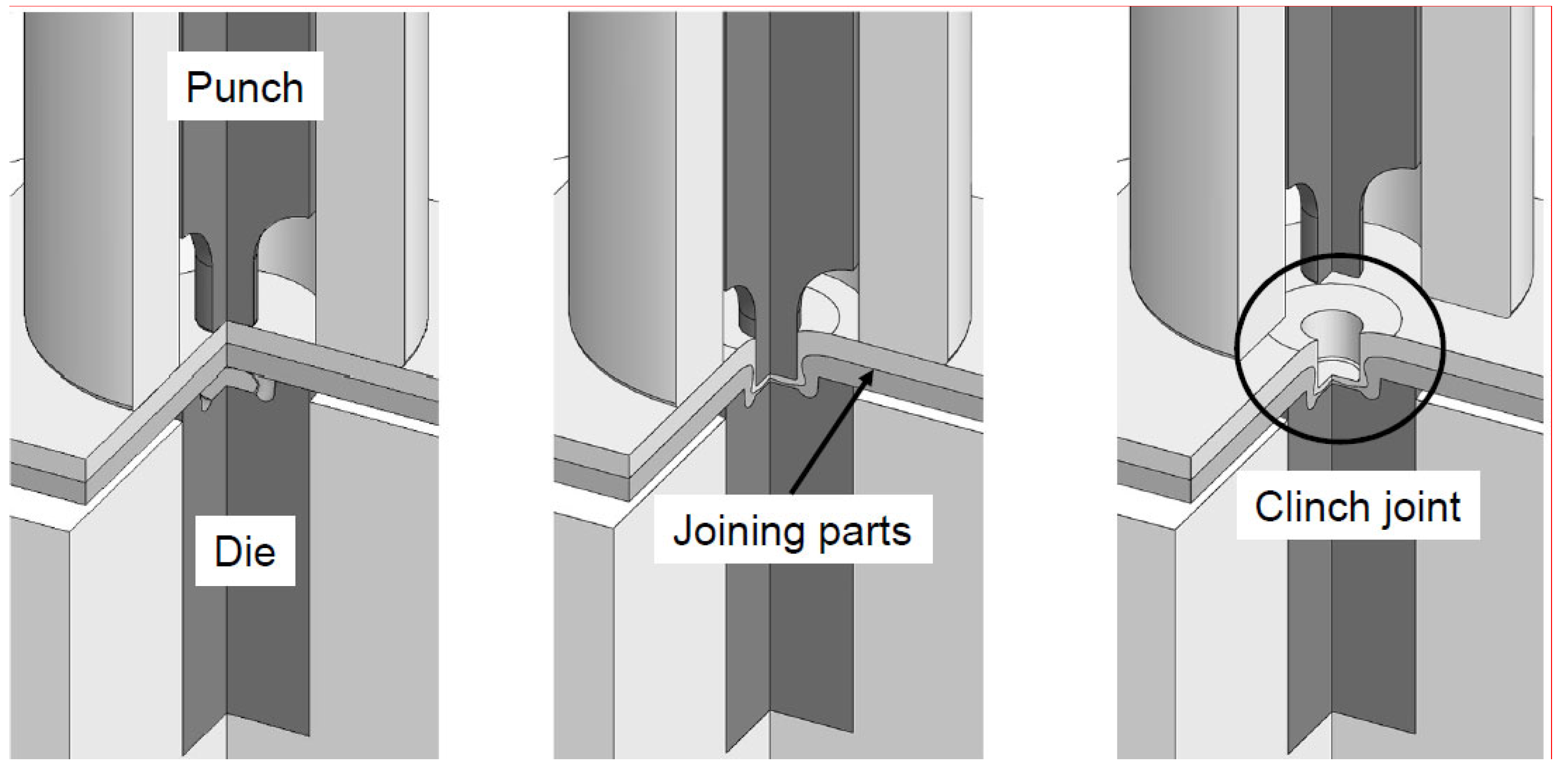
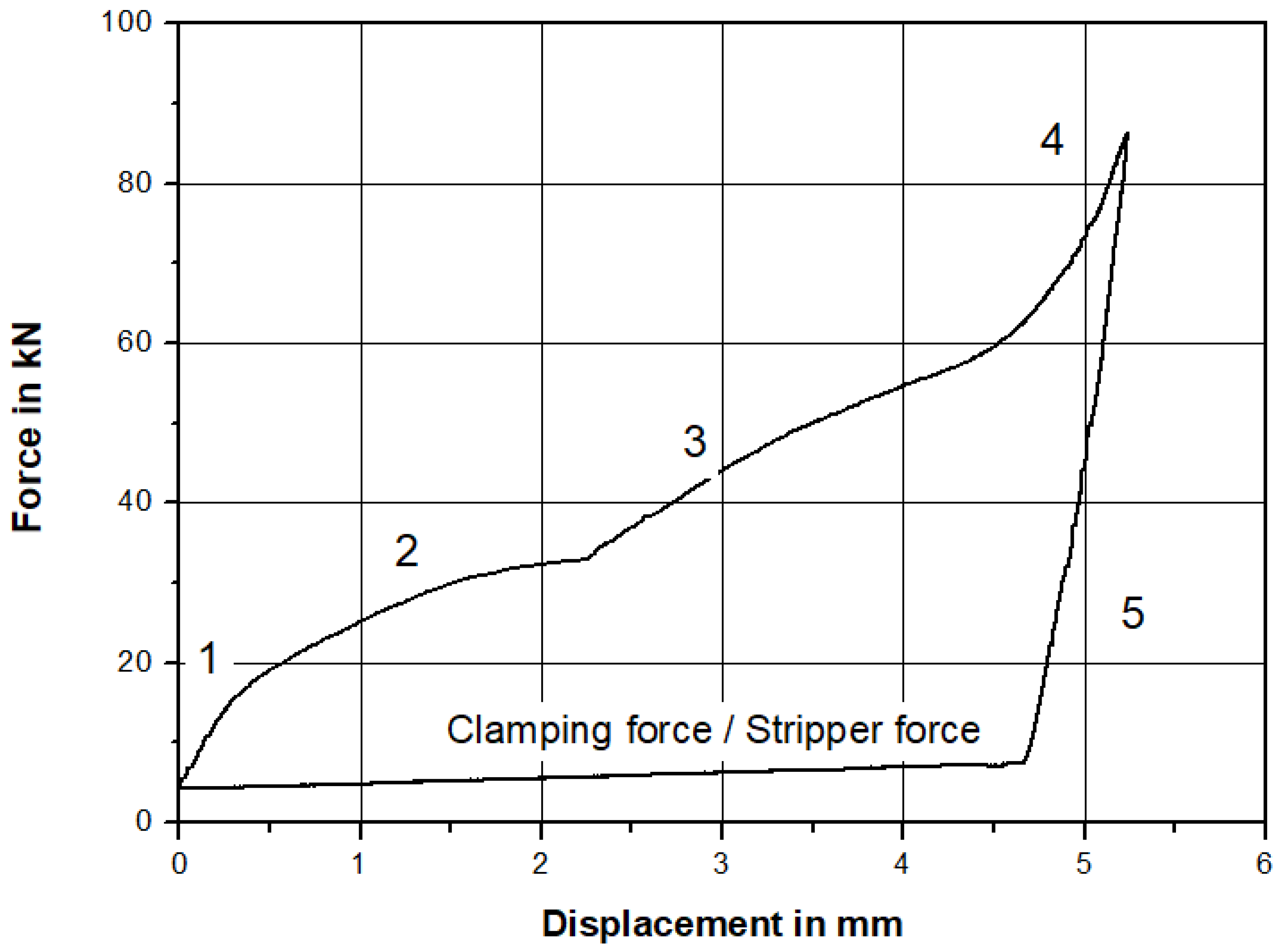
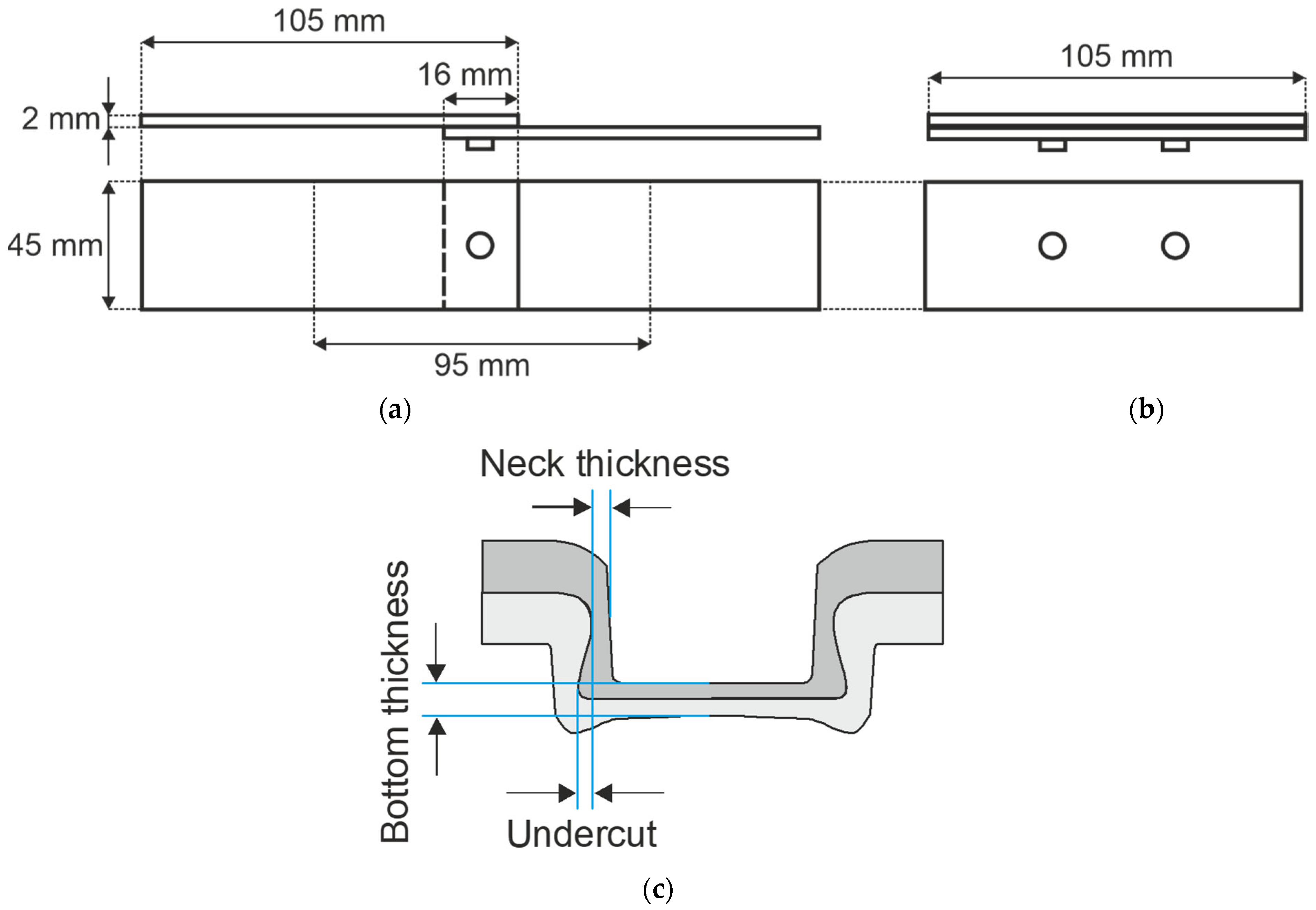
2.2. Characterization of the Clinch Process and Joints
2.3. Mechanical Properties of the Clinch Joints
3. Results
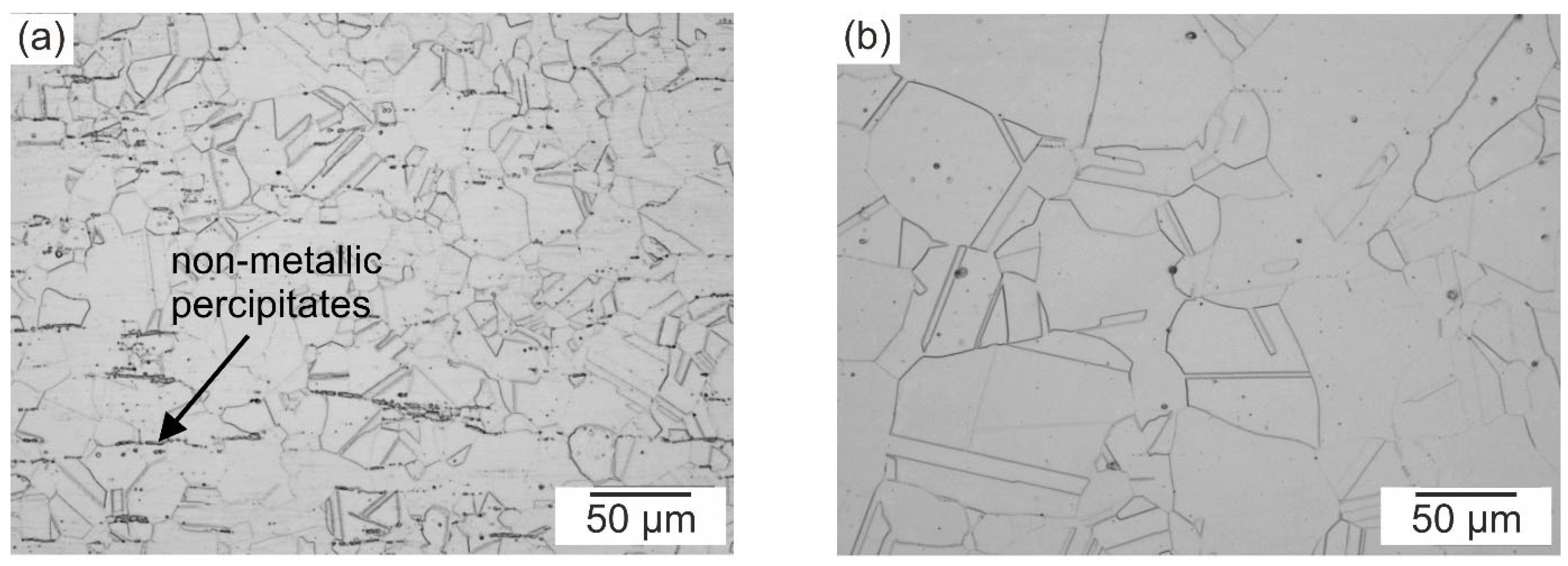
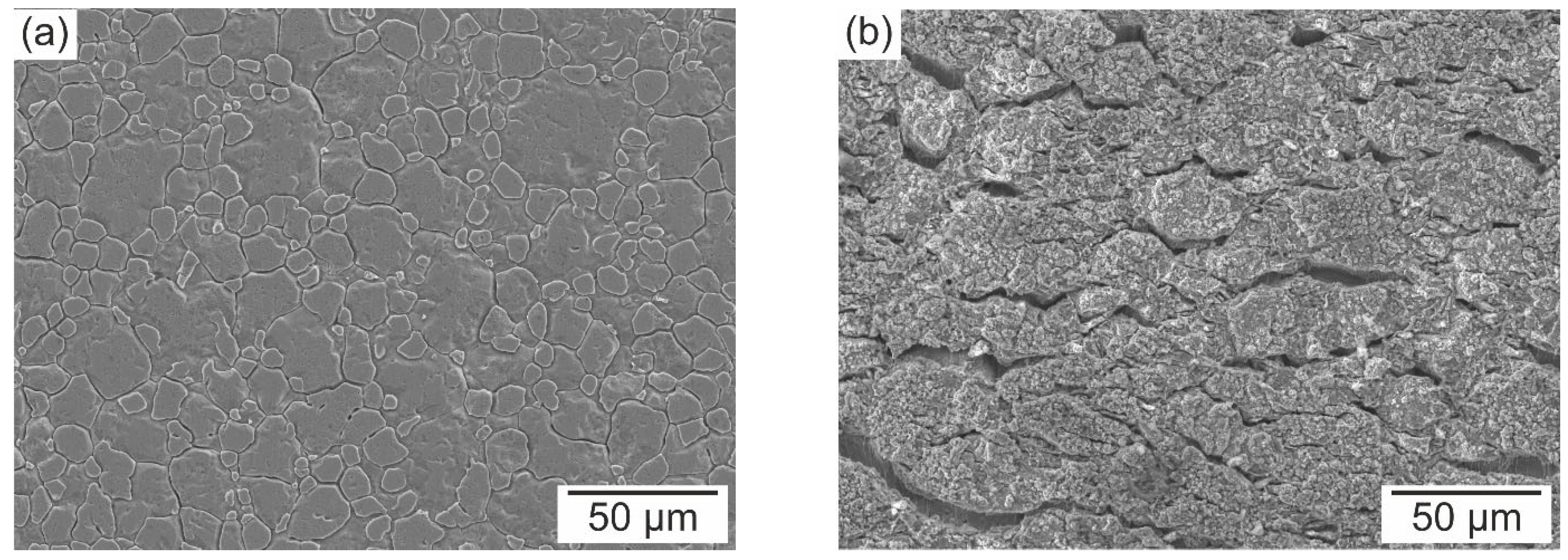
3.1. Characterization of the Initial Conditions
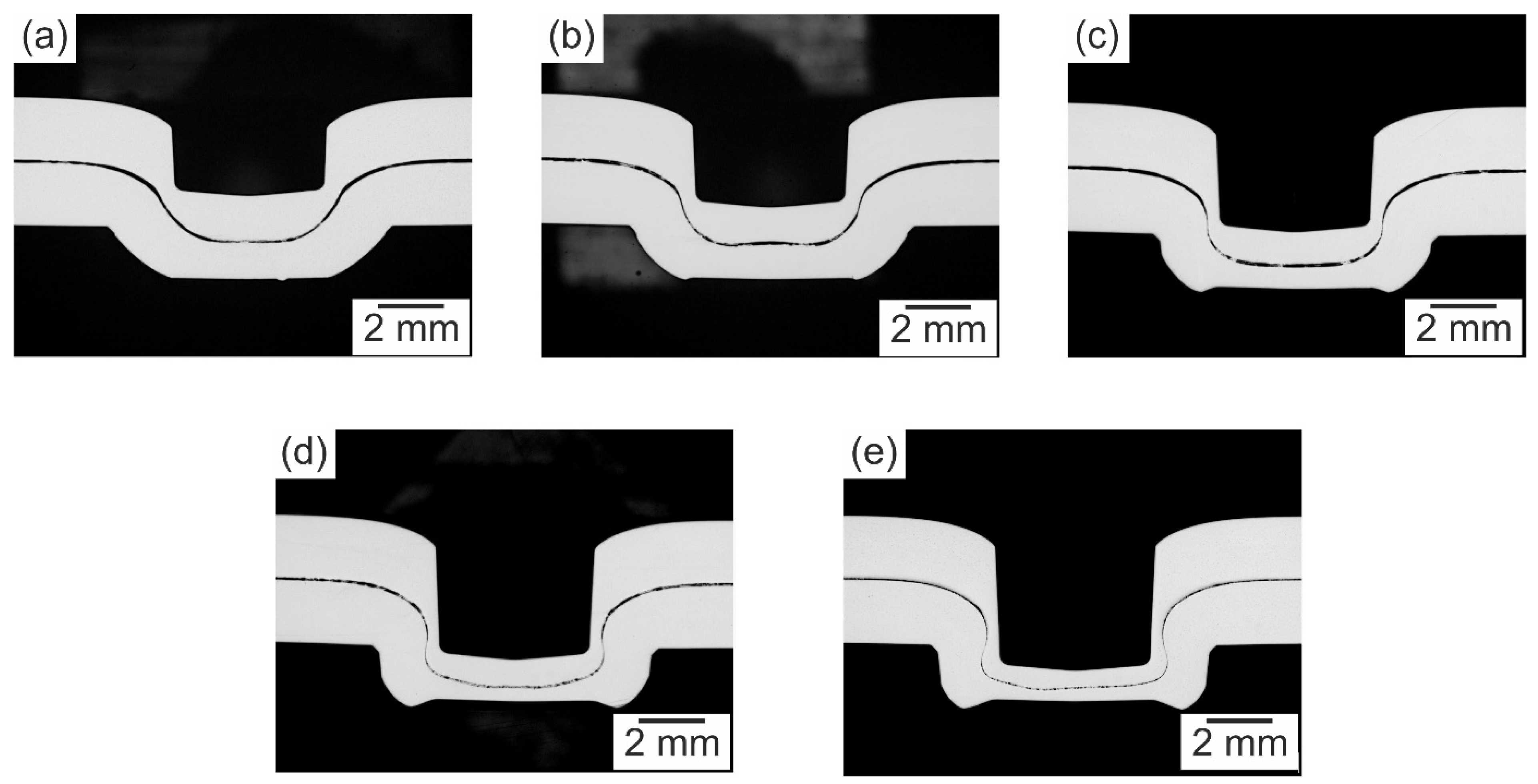
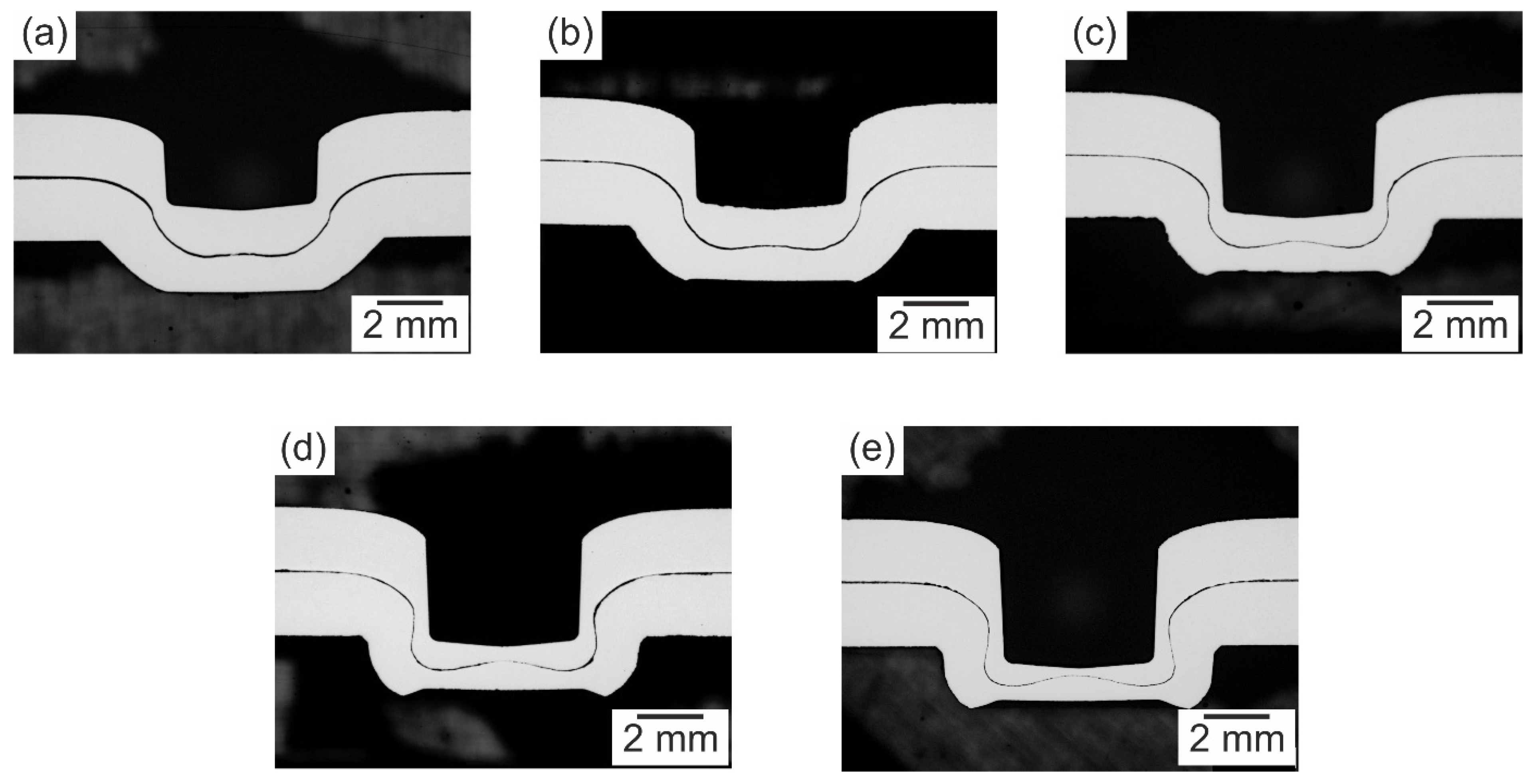
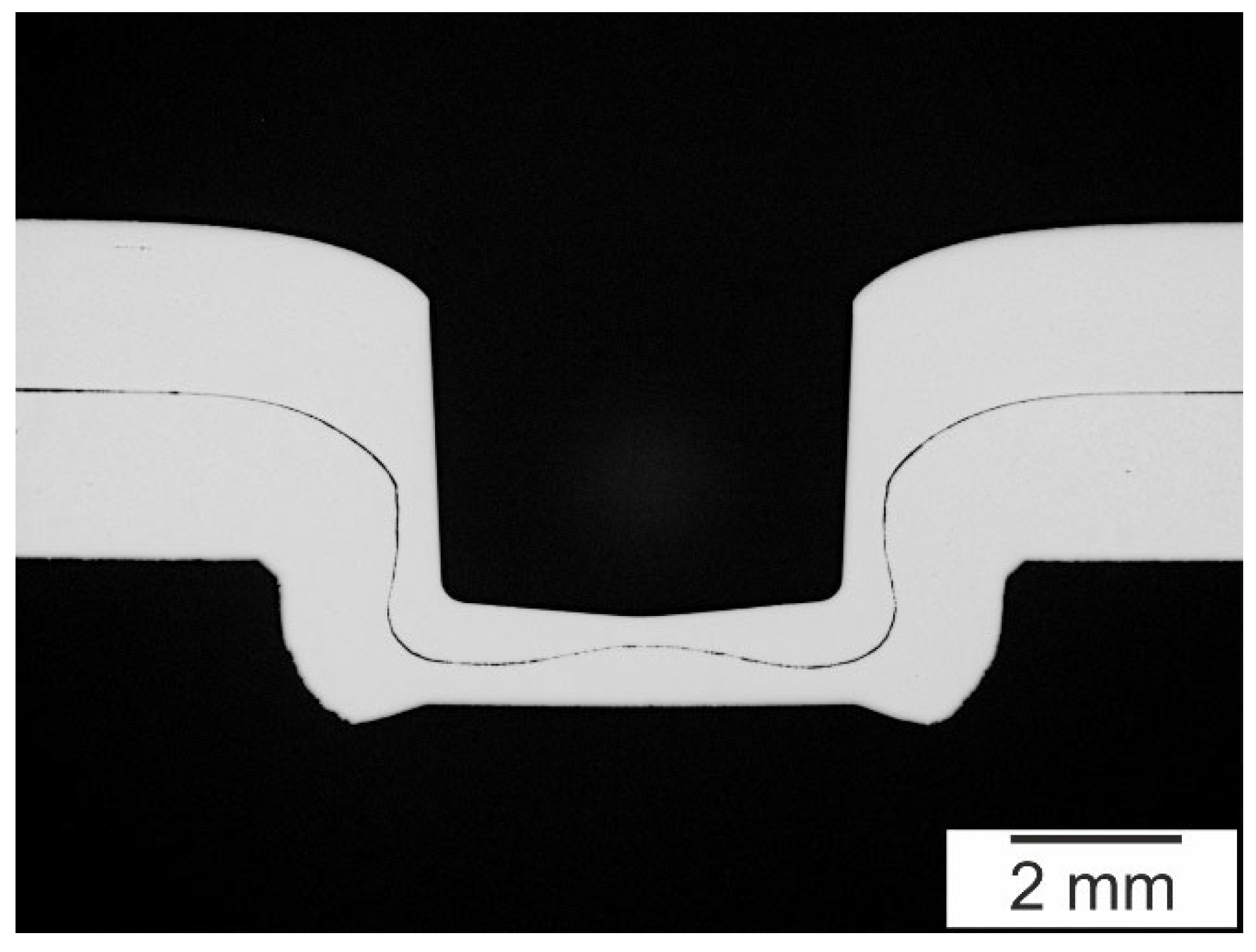
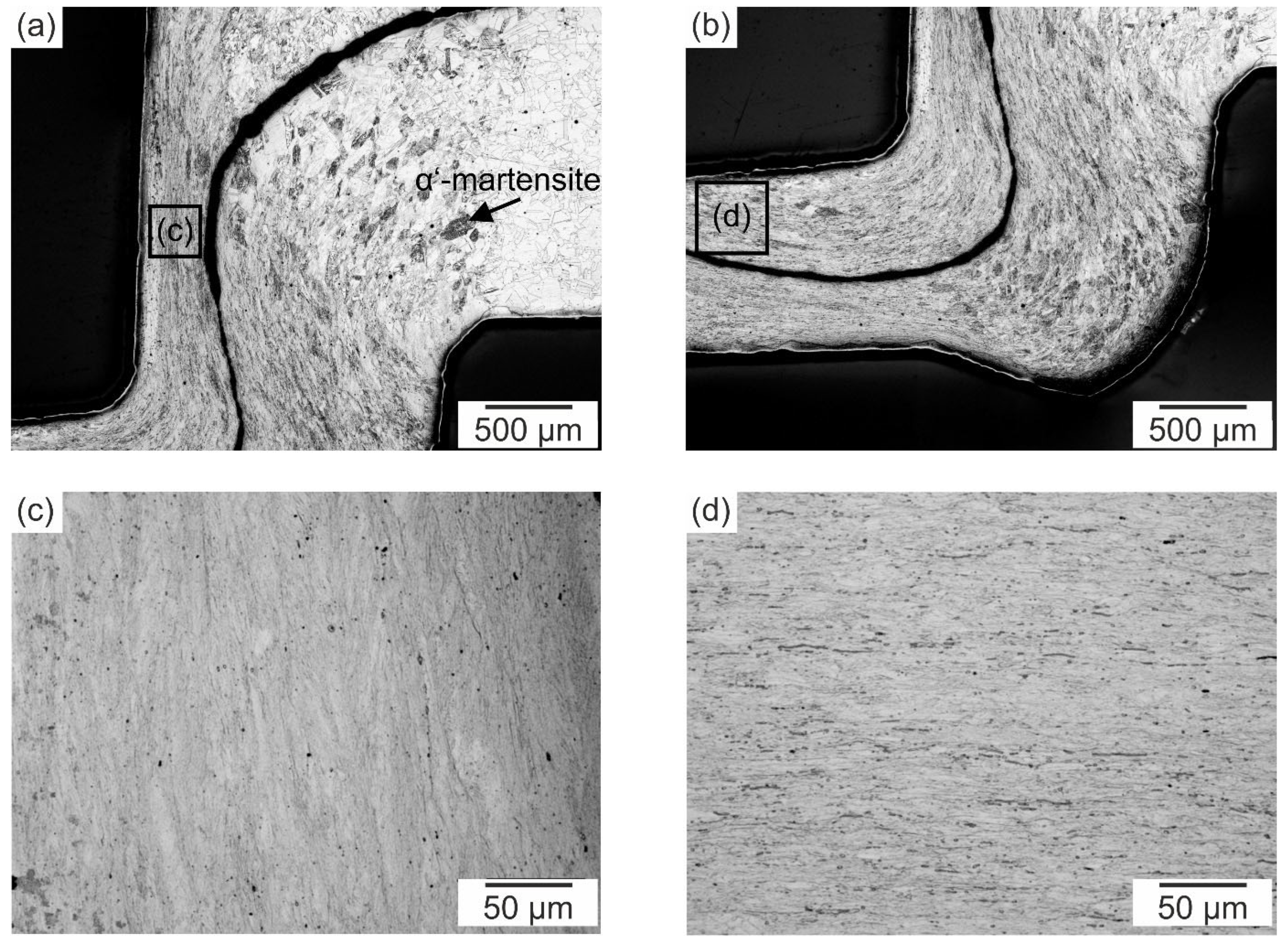
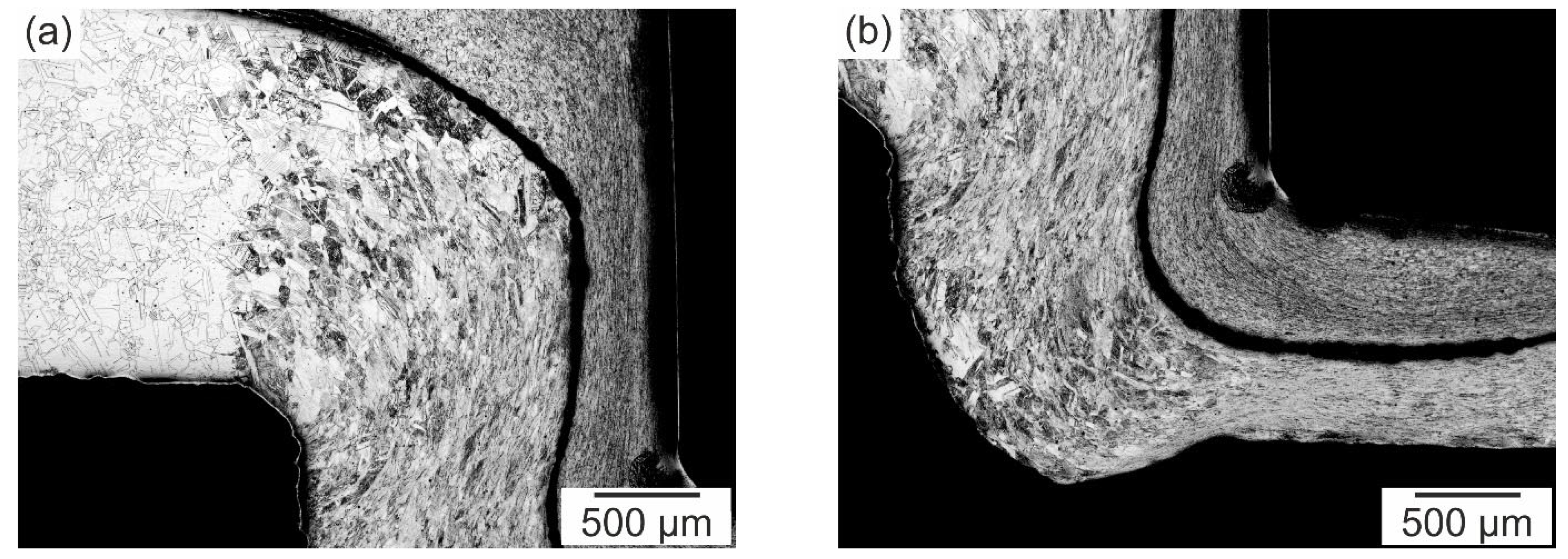
3.2. Characterization of the Clinch Process and Joints
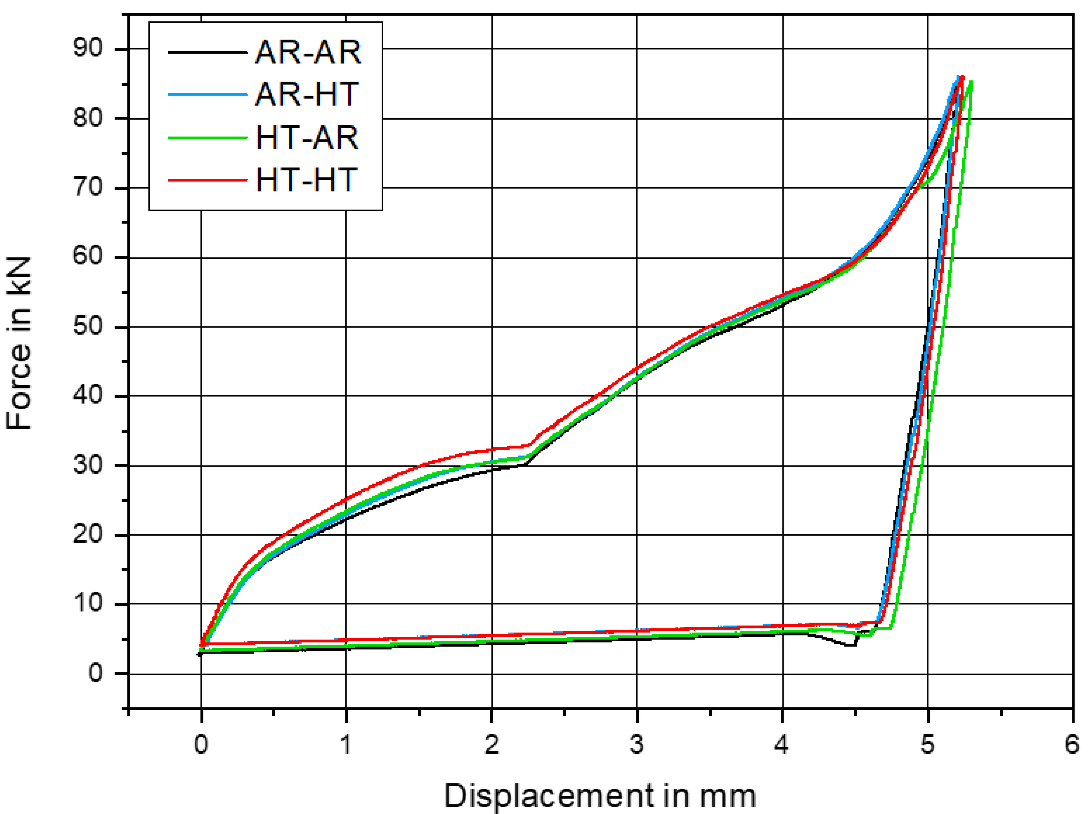
3.3. Mechanical Properties of the Clinch Joints
4. Discussion
5. Conclusions
- -
- The heat treatment resulted in differences in the microstructure and surface condition. The grain size, as well as the roughness, increased significantly.
- -
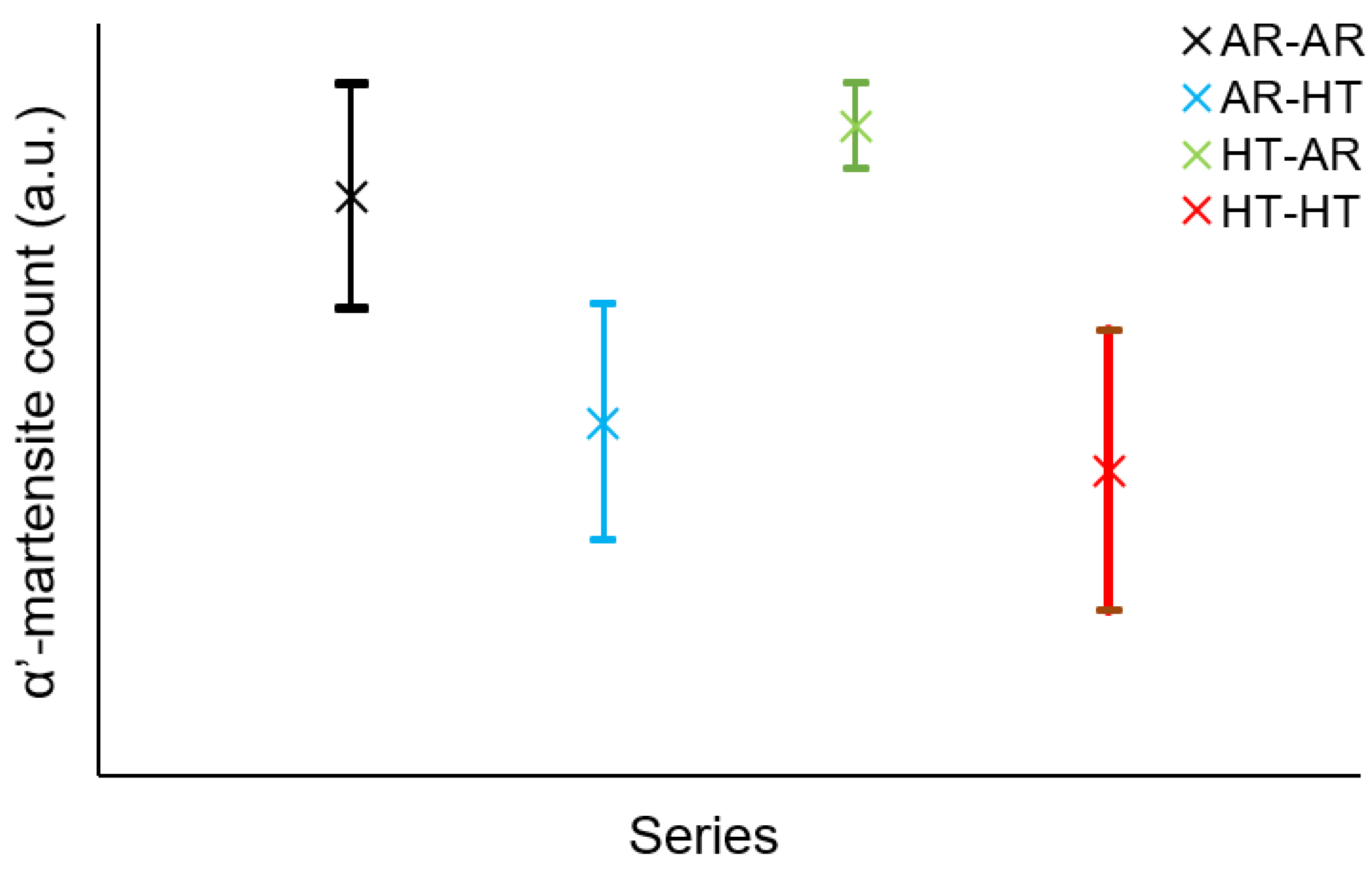
- Although, in the case of the heat-treated sheets, the increased grain size resulted in inhibited DIMT behavior, and the higher surface roughness led to different coefficients of the friction, the differences in the clinch joint fabrication were rather small compared to those observed in the non-heat-treated specimens.
- -
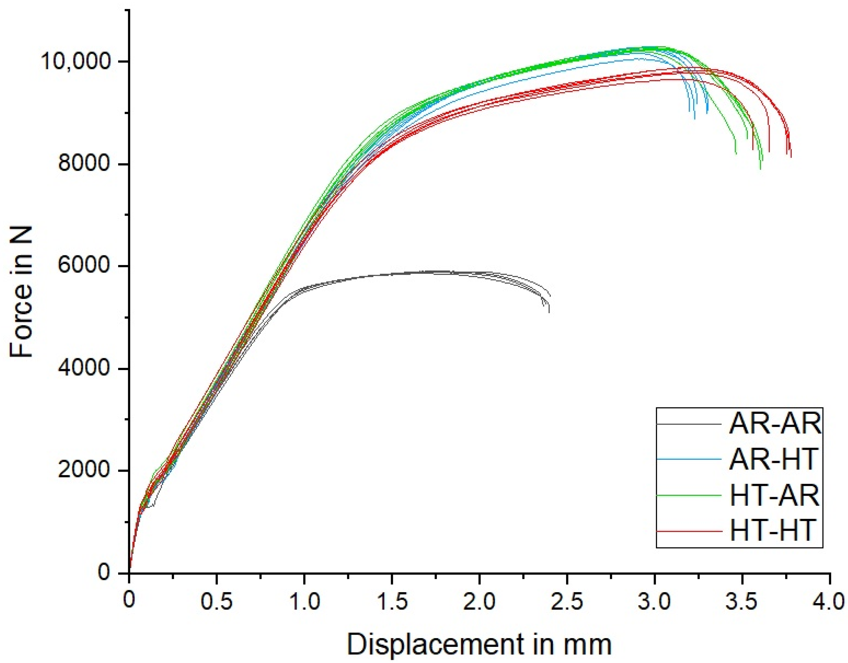
- The HT-AR condition achieved the highest maximum shear tensile forces and displacements. The reason for this is the favorable combination of an increase in the friction coefficients, which does not adversely affect the manufacturing but does counteract the unbuttoning of the connection, and the higher formability of the punch-side sheet in the heat-treated condition.
- -
- DIMT is a complex mechanism influencing AISI 304 clinch joints, as it locally affects the manufacturing process, as well as the mechanical properties, and can lead to great differences in α’-martensite formation depending on the chemical composition of the AISI 304, the manufacturing parameters and the type of loading.
Author Contributions
Funding
Institutional Review Board Statement
Informed Consent Statement
Data Availability Statement
Conflicts of Interest
References
- Abrassart, F. Stress-induced γ → α martensitic transformation in two carbon stainless steels. Application to trip steels. Met. Mater. Trans. A 1973, 4, 2205–2216. [Google Scholar] [CrossRef]
- Rémy, L.; Pineau, A.; Thomas, B. Temperature dependence of stacking fault energy in close-packed metals and alloys. Mater. Sci. Eng. 1978, 36, 47–63. [Google Scholar] [CrossRef]
- Remy, L. Temperature variation of the intrinsic stacking fault energy of a high manganese austenitic steel. Acta Met. 1977, 25, 173–179. [Google Scholar] [CrossRef]
- Pineau, A.G.; Pelloux, R.M. Influence of strain-induced martensitic transformations on fatigue crack growth rates in stainless steels. Met. Mater. Trans. A 1974, 5, 1103–1112. [Google Scholar] [CrossRef]
- Dally, T.; Grigorescu, A.; Müller-Bollenhagen, C.; Zimmermann, M.; Christ, H.-J.; Weinberg, K. Using Martensite Formation during Tube-Forming to Optimize Fatigue Strength. Steel Res. Int. 2014, 85, 1355–1363. [Google Scholar] [CrossRef]
- Guillot, M.; McCormack, T.; Tuffs, M.; Rosochowski, A.; Halliday, S.; Blackwell, P. Shear forming of 304L stainless steel–microstructural aspects. Procedia Eng. 2017, 207, 1719–1724. [Google Scholar] [CrossRef][Green Version]
- Yuying, Y.; Chunfeng, L.; Hongzhi, X. A study of longitudinal cracking and the forming technology for deep-drawn austenitic stainless-steel cups. J. Mater. Process. Technol. 1992, 30, 167–172. [Google Scholar] [CrossRef]
- Lindgren, M.; Bexell, U.; Wikström, L. Roll forming of partially heated cold rolled stainless steel. J. Mater. Process. Technol. 2009, 209, 3117–3124. [Google Scholar] [CrossRef][Green Version]
- Tang, G.; Zhang, J.; Yan, Y.; Zhou, H.; Fang, W. The engineering application of the electroplastic effect in the cold-drawing of stainless steel wire. J. Mater. Process. Technol. 2003, 137, 96–99. [Google Scholar] [CrossRef]
- Müller-Bollenhagen, C.; Zimmermann, M.; Christ, H.-J. Very high cycle fatigue behaviour of austenitic stainless steel and the effect of strain-induced martensite. Int. J. Fatigue 2010, 32, 936–942. [Google Scholar] [CrossRef]
- Tourki, Z.; Bargui, H.; Sidhom, H. The kinetic of induced martensitic formation and its effect on forming limit curves in the AISI 304 stainless steel. J. Mater. Process. Technol. 2005, 166, 330–336. [Google Scholar] [CrossRef]
- Pham, C.H.; Thuillier, S.; Manach, P.-Y. Prediction of flow stress and surface roughness of stainless steel sheets considering an inhomogeneous microstructure. Mater. Sci. Eng. A 2016, 678, 377–388. [Google Scholar] [CrossRef]
- Man, J.; Smaga, M.; Kuběna, I.; Eifler, D.; Polák, J. Effect of metallurgical variables on the austenite stability in fatigued AISI 304 type steels. Eng. Fract. Mech. 2017, 185, 139–159. [Google Scholar] [CrossRef]
- Olson, G.B.; Cohen, M. A general mechanism of martensitic nucleation: Part I. General concepts and the FCC → HCP transformation. Met. Mater. Trans. A 1976, 7, 1897–1904. [Google Scholar] [CrossRef]
- Olson, G.B.; Cohen, M. A general mechanism of martensitic nucleation: Part II. FCC → BCC and other martensitic transformations. Met. Mater. Trans. A 1976, 7, 1905–1914. [Google Scholar] [CrossRef]
- Milad, M.; Zreiba, N.; Elhalouani, F.; Baradai, C. The effect of cold work on structure and properties of AISI 304 stainless steel. J. Mater. Process. Technol. 2008, 203, 80–85. [Google Scholar] [CrossRef]
- Zheng, C.; Liu, C.; Ren, M.; Jiang, H.; Li, L. Microstructure and mechanical behavior of an AISI 304 austenitic stainless steel prepared by cold- or cryogenic-rolling and annealing. Mater. Sci. Eng. A 2018, 724, 260–268. [Google Scholar] [CrossRef]
- DIN 8593-5:2003-09; Fertigungsverfahren Fügen_-Teil_5: Fügen durch Umformen; Einordnung, Unterteilung, Begriffe. Beuth Verlag GmbH: Berlin, Germany.
- Mori, K.-I.; Abe, Y. A review on mechanical joining of aluminium and high strength steel sheets by plastic deformation. Int. J. Light. Mater. Manuf. 2018, 1, 1–11. [Google Scholar] [CrossRef]
- Reich, M.; Osten, J.; Kozlov, N.; Kessler, O.; Kalich, J. Thermo-Mechanical Simulation of Laser Beam Assisted Clinching for High-Strength Steel. In Thermal Process Modeling, Proceedings from the 5th International Conference on Thermal Process Modeling and Computer Simulation, Gaylord Palms Resort & Convention Center, Orlando, FL, USA, 16–18 June 2014; Ferguson, B.L., Ed.; ASM International: Materials Park, OH, USA, 2014; pp. 39–45. ISBN 9781627080682. [Google Scholar]
- DIN EN ISO 14273:2016-11; Widerstandsschweißen_-Zerstörende Prüfung von Schweißverbindungen_-Probenmaße und Verfahren für die Scherzugprüfung an Widerstandspunkt-, Rollennaht- und Buckelschweißungen mit geprägten Buckeln (ISO_14273:2016); Deutsche Fassung EN_ISO_14273:2016. Beuth Verlag GmbH: Berlin, Germany.
- Hadadzadeh, A.; Mokdad, F.; Wells, M.A.; Chen, D.L. A new grain orientation spread approach to analyze the dynamic recrystallization behavior of a cast-homogenized Mg-Zn-Zr alloy using electron backscattered diffraction. Mater. Sci. Eng. A 2018, 709, 285–289. [Google Scholar] [CrossRef]
- Jónás, S.; Tisza, M. Effect of the Friction Coefficient on Clinch Joints. Int. J. Eng. Manag. Sci. 2020, 5, 86–90. [Google Scholar] [CrossRef]
- Steinfelder, C.; Kalich, J.; Brosius, A.; Füssel, U. Numerical and experimental investigation of the transmission moment of clinching points. IOP Conf. Ser. Mater. Sci. Eng. 2021, 1157, 012003. [Google Scholar] [CrossRef]
- Bielak, C.R.; Böhnke, M.; Bobbert, M.; Meschut, G. Further development of a numerical method for analyzing the load capacity of clinched joints in versatile process chains. ESAFORM 2021, 24. [Google Scholar] [CrossRef]
- NaghiZadeh, M.; Mirzadeh, H. Effects of Grain Size on Mechanical Properties and Work-Hardening Behavior of AISI 304 Austenitic Stainless Steel. Steel Res. Int. 2019, 90, 1900153. [Google Scholar] [CrossRef]
- Zeuner, A.T.; Kühne, R.; Standke, C.; Köberlin, D.; Wanski, T.; Schettler, S.; Füssel, U.; Zimmermann, M. Fatigue Behavior of Laser-Cut Sheet Metal Parts with Brazed-On Elements. Metals 2021, 11, 2063. [Google Scholar] [CrossRef]
- Bielak, C.; Böhnke, M.; Beck, R.; Bobbert, M.; Meschut, G. Numerical analysis of the robustness of clinching process considering the pre-forming of the parts. J. Adv. Join. Process. 2021, 3, 100038. [Google Scholar] [CrossRef]
- Kalich, J.; Füssel, U. Design of clinched joints on the basis of binding mechanisms. Prod. Eng. Res. Devel. 2022, 16, 213–222. [Google Scholar] [CrossRef]
- Abe, Y.; Kato, T.; Mori, K.-I.; Nishino, S. Mechanical clinching of ultra-high strength steel sheets and strength of joints. J. Mater. Process. Technol. 2014, 214, 2112–2118. [Google Scholar] [CrossRef]
- Ewenz, L.; Kalich, J.; Zimmermann, M.; Füssel, U. Effect of Different Tool Geometries on the Mechanical Properties of Al-Al Clinch Joints. Key Eng. Mater. 2021, 883, 65–72. [Google Scholar] [CrossRef]
- Barat, K.; Bar, H.N.; Mandal, D.; Roy, H.; Sivaprasad, S.; Tarafder, S. Low temperature tensile deformation and acoustic emission signal characteristics of AISI 304LN stainless steel. Mater. Sci. Eng. A 2014, 597, 37–45. [Google Scholar] [CrossRef]


| Element | C | Si | Mn | P | S | Cr | Ni | N | Fe |
|---|---|---|---|---|---|---|---|---|---|
| Wt-% | 0.038 | 0.46 | 1.28 | 0.02 | 0.002 | 18.29 | 8.55 | 0.07 | bal. |
| Element | O | Cr | Fe | Mn | Si |
|---|---|---|---|---|---|
| Cr-Rich | 65.4 | 20.9 | 6.8 | 0.3 | - |
| Fe-Rich | 59.6 | 3.9 | 35.9 | 5.6 | 0.7 |
| Condition | AR | HT |
|---|---|---|
| Ra [µm] | 0.20 | 1.58 |
| Rz [µm] | 2.00 | 11.92 |
| Dimensions in mm | Neck Thickness Left Side | Neck Thickness Right Side | Undercut Left Side | Undercut Right Side | Bottom Thickness Punch-Side | Bottom Thickness Die-Side |
|---|---|---|---|---|---|---|
| AR-AR | 0.37 | 0.34 | 0.18 | 0.16 | 0.51 | 0.43 |
| AR-HT | 0.47 | 0.46 | 0.11 | 0.13 | 0.34 | 0.70 |
| HT-AR | 0.42 | 0.42 | 0.11 | 0.12 | 0.45 | 0.56 |
| HT-HT | 0.42 | 0.42 | 0.14 | 0.18 | 0.22 | 0.79 |
| Series | AR-AR | AR-HT | HT-AR | HT-HT | |
|---|---|---|---|---|---|
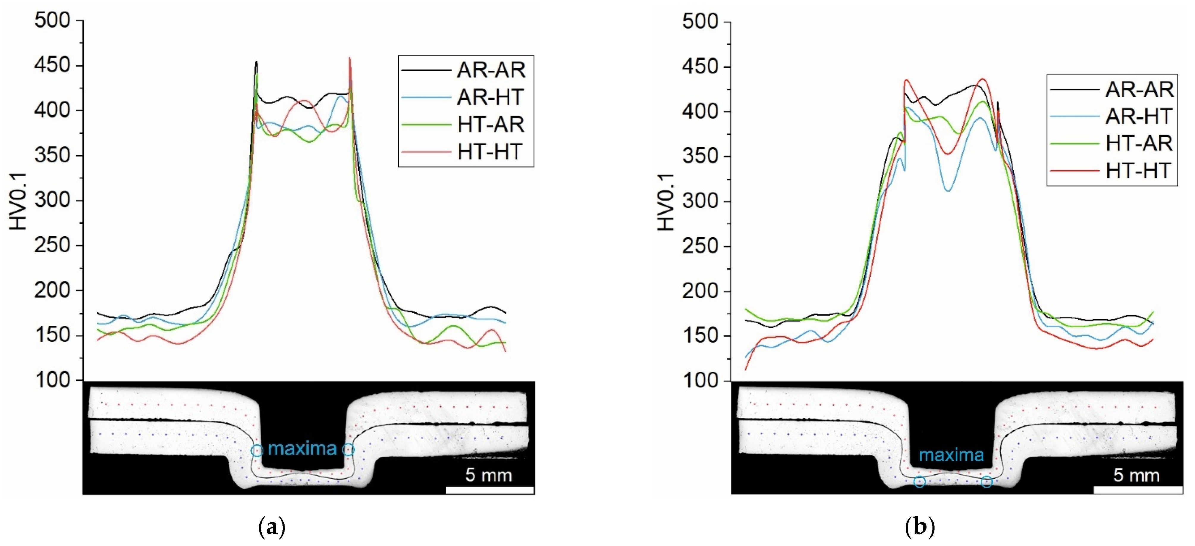
| HV0.1, punch-side sheet | Bottom, mean value | 412 ± 8 | 388 ± 20 | 376 ± 9 | 389 ± 19 |
| Neck, maximum | 474 | 442 | 454 | 470 | |
| HV0.1, die-side sheet | Bottom, mean value | 418 ± 11 | 371 ± 38 | 394 ± 16 | 399 ± 35 |
| Neck, maximum | 435 | 409 | 420 | 450 | |
| Series | Fmax (N) | Displacement (mm) |
|---|---|---|
| AR-AR | 5886 ± 18 | 2.4 ± 0.02 |
| AR-HT | 10,203 ± 97 | 3.3 ± 0.04 |
| HT-AR | 10,249 ± 32 | 3.6 ± 0.1 |
| HT-HT | 9807 ± 95 | 3.7 ± 0.1 |
Publisher’s Note: MDPI stays neutral with regard to jurisdictional claims in published maps and institutional affiliations. |
© 2022 by the authors. Licensee MDPI, Basel, Switzerland. This article is an open access article distributed under the terms and conditions of the Creative Commons Attribution (CC BY) license (https://creativecommons.org/licenses/by/4.0/).
Share and Cite
Zeuner, A.T.; Ewenz, L.; Kalich, J.; Schöne, S.; Füssel, U.; Zimmermann, M. The Influence of Heat Treatment on the Microstructure, Surface Roughness and Shear Tensile Strength of AISI 304 Clinch Joints. Metals 2022, 12, 1514. https://doi.org/10.3390/met12091514
Zeuner AT, Ewenz L, Kalich J, Schöne S, Füssel U, Zimmermann M. The Influence of Heat Treatment on the Microstructure, Surface Roughness and Shear Tensile Strength of AISI 304 Clinch Joints. Metals. 2022; 12(9):1514. https://doi.org/10.3390/met12091514
Chicago/Turabian StyleZeuner, André Till, Lars Ewenz, Jan Kalich, Sebastian Schöne, Uwe Füssel, and Martina Zimmermann. 2022. "The Influence of Heat Treatment on the Microstructure, Surface Roughness and Shear Tensile Strength of AISI 304 Clinch Joints" Metals 12, no. 9: 1514. https://doi.org/10.3390/met12091514
APA StyleZeuner, A. T., Ewenz, L., Kalich, J., Schöne, S., Füssel, U., & Zimmermann, M. (2022). The Influence of Heat Treatment on the Microstructure, Surface Roughness and Shear Tensile Strength of AISI 304 Clinch Joints. Metals, 12(9), 1514. https://doi.org/10.3390/met12091514