Abstract
The research on structural features, microhardness distribution, and deformation features of Vit105 bulk metallic glass (BMG) before and after high-pressure torsion (HPT), as well as after relaxing annealing, has been carried out. HPT n = 1 leads to an increase in free volume ΔV, and relaxing annealing leads to a decrease in ΔV and non-uniformity relative to the initial state of BMG. In the initial BMG and in the BMG after relaxing annealing, microhardness is uniformly distributed over the surface, while in the material subjected to HPT, the microhardness distribution is more heterogeneous. The bonded-interface indentation of the BMG has been conducted in different states. The formation of numerous concentric bands around the indenter is observed. The pattern of band distribution is more homogenous in Vit105 BMG alloy before HPT. In relaxed samples, the bands often have fractures and irregularities, as well as cracks that can be seen under the indents. After HPT, the formation of several intensity bands can be observed, as well as a number of low-intensity ones between the main intensity bands. The average distance between the bands in the initial BMG and BMG after HPT is close to identical, while the distance between the bands is smaller in the relaxed state, which reflects the lower plasticity of the material after annealing.
1. Introduction
In recent years, bulk metal glasses (BMG) have been intensively investigated [1,2,3]. The compositions of the BMG alloys are selected in such a way that an amorphous structure can be obtained even at a cooling rate of about 102 K/s, which makes it possible to obtain bulk amorphous samples up to several centimetres in diameter. Today these materials have been used in certain types of technology [4].
Deformation of amorphous alloys and BMG is carried out mainly due to the formation and propagation of shear bands (SBs)—narrow, 10–50 nm thick, deformation zones [5,6]. This feature leads to the fact that amorphous alloys demonstrate extremely low plasticity under tension—the very first formed SB becomes a stress concentrator and deformation occurs until the sample is fractured. At the same time, during compression or bending, when compressive stresses appear in addition to tensile stresses, amorphous alloys can show some plasticity [1,4]. In this regard, numerous studies have been undertaken to improve the plasticity of amorphous alloys [6,7,8,9,10].
An increase in plasticity and an improvement in mechanical properties is possible through modifying the chemical composition, as well as through various additional treatments [1,2,9,11,12,13]. One way to increase plasticity is the preliminary formation of a high density of SBs in the amorphous phase or the formation of inhomogeneous nanocluster amorphous structures [6,7,8,9]. For example, preliminary deformation by cold rolling, compression, etc., enables an increase in the ductility of BMG due to the nucleation of secondary SBs and branching of primary SBs under consequent loading [6,7]. As a result, the overall plasticity increases [6,7,8,9]. However, conventional deformation methods do not make it possible to achieve large deformations in the case of brittle amorphous materials.
A promising method for introducing high deformation and, consequently, a high density of structural defects into an amorphous solid is the use of high-pressure torsion (HPT) [14,15]. The HPT process is one of the most powerful techniques to prepare ultrafine-grained materials due to severe deformation [14,15]. Numerous publications have been devoted to the study of the effect of HPT on the structure and properties of amorphous alloys [16,17,18,19,20,21,22,23,24,25,26,27]. Recently, there have been few reviews on this topic, in particular [28,29].
It was shown that HPT led to partial nanocrystallization in amorphous alloys of some compositions [17,18,21,22,25]. In amorphous alloys of other compositions, nanocrystallization is not observed during HPT; however, HPT leads to changes in the amorphous phase, the formation of inhomogeneities in the amorphous structure occurs, and free volume increases, which in some cases causes a change in alloy properties [19,23,26].
The study of the deformation behaviour in BMG previously exposed to HPT is not an easy task. Specimens after HPT usually have the form of discs 10 mm in diameter and 0.5 mm thick [27,28,29], and it is difficult to perform compression or three-point bending tests on specimens of this geometry. Upon tensile stress, BMG samples usually experience a brittle fracture. Indentation and nanoindentation methods, owing to their ability to induce permanent deformation in a controlled manner even in highly brittle materials, are widely used for studying the mechanical behaviour of amorphous materials [30,31,32]. Thus, measurements by nanoindentation demonstrate that HPT leads to a decrease in the elastic modulus of BMG, a decrease in hardness, and an increase in strain rate sensitivity relative to the initial condition [27]. Note that the tensile ductility of Zr65Al7.5Ni10Cu12.5Pd5 BMG after HPT was reported in [26]. The authors assumed that the work-hardening behaviour with a tensile ductility of Zr-BMG resulted from the multiple SBs caused by the distribution of heterogeneities in BMG after HPT [26].
It is of interest to study the pattern of deformation of BMG pre-processed HPT—the formation and propagation of SBs under loading and other deformation features. An effective method proposed for assessing the formation and propagation of SBs on amorphous materials is the bonded-interface indentation technique [33]. In the bonded-interface indentation technique, two samples of amorphous alloy with polished top and side faces are fixed together in the clamp, after which indentation is carried out into the joint of the two samples (Figure 1a). Previously, a similar method was used to observe the steps on the surface due to the formation of SBs in BMG Vitreloy 106 Zr57Nb5Ni12.6Cu15.4Al10, where authors performed Vickers indentations along the joint of the samples and investigated the deformation pattern and the formation of shear bands in the indentation region under different applied loads [33]. Studies have shown that at small indentation loads (10 g), semi-circular primary SBs primarily accommodated the plastic deformation around the indenter. At higher loads (100–1000 g), secondary and tertiary SBs were formed inside this plastic zone. To assess the plastic zone size, and characterize and identify the stress forming under the indenter, the authors used “a modified expanding cavity model” [33]. The role of free volume in the inhomogeneous plastic flow of the BMG was systematically analysed by performing the bonded-interface indentation technique to the as-cast BMG and BMG after relaxation annealing, with a minimum free volume [34]. However, in the latter two mentioned articles, bonded-interface indentation was used to analyse the pattern of deformation only in the as-cast and relaxed state of the BMG. In the present work, indentation was carried out into the joint of the Vit105 BMG alloy in various structured states—before and after HPT, as well as after relaxing annealing.
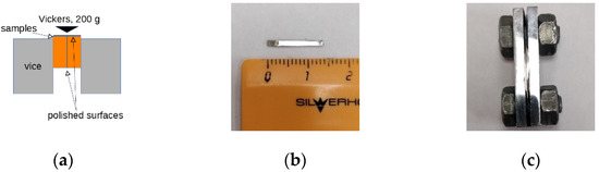
Figure 1.
Joint indentation scheme: (a) samples are clamped in vice polished surfaces to each other; (b) a sample cut from HPT n = 1 BMG; (c) samples are clamped in a vice.
2. Materials and Methods
The Vit105 BMG ingots with a standard composition of Zr52.5Cu17.9Al10Ni14.6Ti5 (at %) were prepared by arc melting using pure (>99.9%) components under a Ti-gettered pure argon atmosphere. The ingots were remelted four times for chemical homogeneity. The melt was subsequently cast into a water-cooled suction casting machine with a copper mould at a cooling rate of 102 K/s. The ingots were obtained in the form of 10 × 65 × 2 mm plates.
The X-ray diffraction (XRD) analysis of the BMG samples was conducted using the Bruker D2 Phaser (Bruker AXS GmbH, Karlsruhe, Germany) diffractometer with CuKα radiation in the reflected beam; the LynxEye XE-T detector was used. The obtained data were processed using the DIFFRAC.EVA v.5.2 software (Bruker AXS GmbH, Karlsruhe, Germany), including the determination of the centre of gravity position and the full-width at half maximum (FWHM) of the amorphous halo.
According to [35,36], the radius of the first coordination sphere (R1) can be found from the position of the main amorphous halo using the equation:
where θ is the gravity centre angle, and λ is the radiation wavelength [35].
The change in free volume ΔV could be estimated according to:
where R0 and RHPT are the radii of the first coordination sphere of as-cast and HPT-processed BMG, respectively [37].
Vit105 10 mm in diameter and 1 mm thick disk samples were cut out of plates using wire electrical discharge machining and then deformed using HPT anvils with a groove 0.3 mm deep and 10 mm in diameter. One revolution of the anvils was made at the speed of 1 rpm under an applied pressure of 6 GPa at room temperature. Some of the initial samples were subjected to relaxing annealing in a vacuum furnace VacETO D-4,5.3.E-16UU-IV (NPP VacETO LLC, Moscow, Russia), the residual air pressure at the beginning of the cycle was 10−5 Pa. The annealing temperature was 430 °C, the dwell time at the temperature was 10 min, and the heating rate of 20 K/min was used.
The Vickers microhardness (HV) was measured at a grid array of points using the spacing of 0.7 mm with loads of 100 g at each point for 10 s, at least 42 points per sample. Then sets of two samples in the form of flat plates 10 × 2 × 0.7 mm in dimensions were cut from the initial BMG, from the HPT-processed disks, and from BMG subjected to relaxing annealing (Figure 1b). The wide faces of the obtained plates were polished to mirror finish, next they were fixed together tightly with a clamp (Figure 1c), and then the top surfaces of the clamped samples were polished to mirror finish. Indentation with load of 200 g was conducted into the joint and as a result, a pattern of SBs was formed under the indenter on the polished surfaces of the samples. Both microindentation and bonded-interface indentation tests were carried out using an Emco-Test Durascan 50 (EMCO-TEST Prüfmaschinen GmbH, Kuchl, Austria) automatic microhardness tester. A set of test bricks MTV-MET (Centre “MET”, Moscow, Russia) was used for the verification of the tester. A scanning electron microscope (SEM) JEOL JSM-6490LV (JEOL Co. Ltd., Tokyo, Japan) was used to study the relief after indentation.
To obtain a stress-strain state diagram during indentation, finite element computer modelling was carried out using the DEFORM-3D (Scientific Forming Technologies Corporation, Columbus, OH, USA) software package. The sample and tool models were created in the KOMPAS-3D (ASCON LLC, Saint Petersburg, Russia) three-dimensional modelling system, saved and imported into DEFORM-3D in the “.stl” format. The volumetric model of the indenter was made in the form of a tetrahedral pyramid with a square base and an apex angle of 136°. For modelling purposes, it was assumed that the initial workpiece was a homogeneous and isotropic plastic body, and the tool was a rigid body. The mechanical behaviour of Vit105 for modelling was determined as follows: the elastic modulus of 90 GPa and Poisson’s ratio of 0.36 were set, and hardening curves were introduced using a tabular form. Until the conventional yield strength (1550 MPa) is reached, the material is deformed elastically and then deformed without hardening, as is typical for BMG. The generated finite element mesh for the workpiece consisted of 150,000 tetrahedrons. Volume compensation option for the model has been used, and the indenter was not meshed. The indentation speed during the simulation was chosen constant and equal to 0.1 mm/sec, at constant room temperature (20 °C). To set the contact behaviour between the indenter and the workpiece, the Siebel friction factor f = 0.12 was used. The impermeability condition was set on the contact surfaces of the rig. The number of simulation steps was 300.
3. Results
3.1. Structure and Microhardness
As can be seen from the XRD analysis, all samples, including as-cast BMG, BMG after relaxation annealing, and BMG after HPT processing, have an amorphous structure (Figure 2). The position of the main amorphous halo gravity centre after HPT shifts towards the lower angles (Table 1). A decrease in the angular position of the amorphous halo after HPT means an increase in R1. According to calculations from Equation (2), HPT n = 1 leads to a ≈ 0.5% increase in ΔV and also leads to an increase in the values of the FWHM of the amorphous halo by 14% (Table 1). The increase in FWHM is also related to an increase in ΔV [38] and to an increase in the inhomogeneity of the amorphous phase [36,39]. Relaxing annealing leads to a shift of the halo to the higher angles, and to a decrease in R1 and the decrease in ΔV and FWHM relative to the initial state of BMG (Table 1), and all of this indicates a decrease in the non-equilibrium state of BMG because of relaxing annealing.
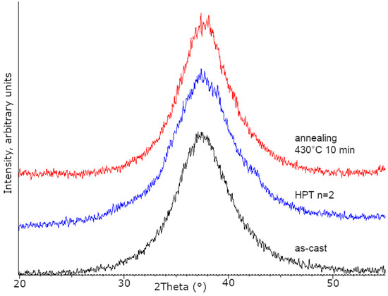
Figure 2.
XRD results for the Vit105 BMG: as-cast; after HPT n = 2, BMG after relaxation annealing.

Table 1.
Amorphous structure parameters in Vit105 BMG in various states: first amorphous halo gravity centre position 2θ, radius of the first coordination sphere R1, full-width at half maximum (FWHM), change in free volume ΔV, and microhardness HV0.1.
An increase in FWHM and the free volume ΔV in Vit105 BMG as a result of HPT means an increase in the non-equilibrium of the amorphic phase. Previously, differential scanning calorimetry data also showed that the relaxation energy Hrelax increased as a result of HPT treatment, causing an increase in the excess free volume from ~0.2% in the initial BMG to 0.5% after HPT [40]; while after relaxing annealing, the excess free volume was close to zero.
The microhardness of the initial BMG Vit105 is 514 ± 13HV0.1, similar values of the microhardness for the same alloy were mentioned in other works [41]. In the initial material, microhardness is characterized by a small scatter of values, only slightly higher than the instrumental error (±10 HV0.2) measured on test brick, which indicates a high homogeneity of the material (Table 1, Figure 3a). In the sample subjected to HPT, there is a slight decrease in microhardness in comparison with the initial state, by ~15 units, and this is probably the result of an increase in free volume. However, the values of HV in this state have a rather large scatter, indicating an increase in the heterogeneity of BMG after HPT (Figure 3b). A similar decrease in HV as a result of HPT was observed by other authors [19,27]. Relaxing annealing leads to a significant increase in microhardness (Table 1), but the uniformity of its distribution over the sample remains close to identical to the initial BMG (Figure 3c).
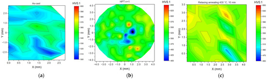
Figure 3.
Microhardness distribution: (a) in the initial sample; (b) after HPT n = 1; (c) after relaxing annealing at 430 °C, 10 min.
Moreover, recent studies have shown that slippage appears during HPT, and deformation is provided not by simple torsion, but in a more complex stress-strain condition, probably, due to precession or misalignment of anvils, which in a way may lead to heterogeneity [42,43].
3.2. Bonded-Interface Indentation
In the first stage, bonded-interface indentation tests were carried out on samples fixed in a rigid steel clamp without gaskets between samples. Figure 4b,c, shows the SEM snapshot of the initial state BMG surface after bonded interface. Numerous concentric bands shifting around the indenter can be observed, but also there is a local area directly under the indents where there are no noticeable SBs—an “SB-free zone” (Figure 4b).
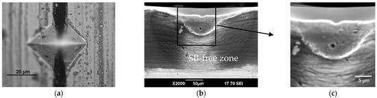
Figure 4.
Bonded indentation of the tightly fixed samples of BMG Vit105 in the initial state: (a) top view; (b) deformation area on the side surface area near the indent (SEM); (c) same, enlarged.
An analysis of the observed pattern confirms that the appearance of the SB-free zone is caused by the following circumstances: the samples are deformed granted that bonded-interface indentation tests are made on samples that are fixed in a rigid steel clamp, without gaskets between them, and with the extrusion of material into the gap. In the area directly under the indenter, the deformation is the highest, and the deformable material of two compressed samples contacts with a significant force (Figure 4c), resulting in the SBs being “strayed” and forming an SB-free zone.
In this regard, in the following experiment, a polyethylene gasket with a thickness of 40 µm was inserted between BMG samples fixed in a rigid steel clamp. As can be seen in Figure 5b, the gasket prevents the deformed material from contacting the two halves of the BMG in the indentation point.
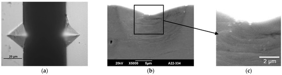
Figure 5.
Bonded indentation of BMG Vit105 in the initial state fixed with a gasket: (a) top view; (b) deformation area on the side surface area near the indent (SEM); (c) same, enlarged.
The SEM analysis of the BMG surface after indentation into the joint showed that in the initial state, the formation of numerous concentric SBs around the indenter was observed (Figure 5b). A similar formation pattern of SBs was also observed at the interface of BMG Vit106 [33]. The characteristics of the formed pattern (the distance from the tip of the indenter to the farthest observed band (far-end), the number, and the average distance between the bands for each state) are presented in Table 2. One can see that in the initial BMG state, the average distance between the concentric bands is about 0.5 microns. As known, SBs are the main carriers of deformation in amorphous materials and the pattern of band formation corresponds to the pattern of stress and strain distribution during indentation according to simulation data.
Table 2.
Pattern parameters of band formation at bonded-interface indentation tests on BMG Vit105 samples in various states—Distances from the indenter tip imprint to the farthest band, number of observed bands, average distance between bands, [µm]. Where indicated, without parentheses refers to all bands, in parentheses—only to intense shear bands.
3.3. Finite-Element Modelling
The picture after the joint indentation of the BMG, previously subjected to relaxing annealing at a temperature of 430 °C (slightly above Tg) for 10 min, is shown in Figure 6. In relaxed samples, numerous concentric bands are also observed on the lateral surface under the indent. At the same time, the bands often have fractures and irregularities. Under the indents, the crack-exits—discontinuities—are also visible. In this case, the distances between adjacent bands are slightly larger—about 0.75 µm.
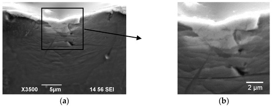
Figure 6.
Bonded indentation of BMG Vit105 after relaxed annealing: (a) deformation area on the side surface area near the indent (SEM); (b) same, enlarged.
A characteristic feature of the samples after HPT, shown in Figure 7, is the formation of several intense bands (with strong contrasts) on the surface under the print, spreading along the circles, and a number of low-intensity bands are observed between the main intense bands. The distance between the latter is about 3 µm, and the average distance between the “main” and small” bands is about 0.5 µm, as in the initial BMG.
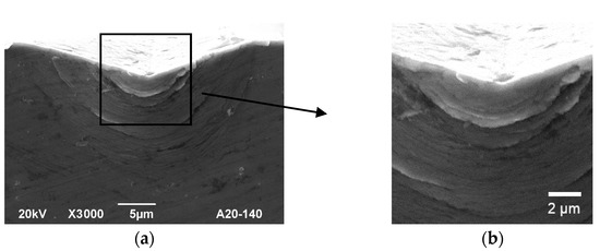
Figure 7.
Bonded indentation of BMG Vit105 after HPT n = 1: (a) deformation area on the side surface area near the indent (SEM); (b) same, enlarged.
The indentation process was simulated using the finite element method; the diagrams of the stress-strain state are shown in Figure 8.
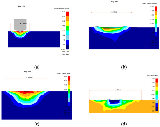
Figure 8.
Diagrams of the stress-strain state under the indenter: (a) stress intensity, general view; (b) the accumulated strain; (c) stress intensity, detailed; (d) mean stress (hydrostatic pressure) values are negative, according to the theory of metal forming for compressive stress).
4. Discussion
As previously mentioned, SBs are the main carriers of deformation in amorphous materials. In the initial state, BMG has a certain margin of uniformly distributed free volume and, when under load, SBs are formed quite easily and the pattern of formation of SBs corresponds to the stress pattern and strain distribution generated from simulation data.
A feature of the samples after HPT (Figure 7) is the heterogeneity of the pattern—there are main intense and less intense bands between them. The nature of the formation of such a pattern requires a more detailed study, presumably because the amorphous structure after HPT becomes much more heterogeneous. Hence, there is a large spread of microhardness values over the surface of the HPT samples [44]. The formation of amorphous clusters [40] and the generation of complexly distributed internal stresses in the structure, on which bands of different intensity can be generated at the microscale level, is observed in BMG Vit105 after HPT. At the same time, for the HPT state, the average distance between the bands, taking into account the “main” and “small” ones, is about the same as in the initial BMG. The presence of high intensity/contrast bands, though, presupposes a greater height of the “step” formed by the band and, in general, a greater plasticity flow of the material.
In the state after relaxing annealing, a smaller free volume characterizes the amorphous phase. The resource for the occurrence of shear transformation zones is less, as well as the number of observed bands and, accordingly, their density is somewhat less than in the original BMG (Table 2). This reflects a slightly smaller plastic deformation of the material under the indenter load, and due to a smaller free volume and margin of plasticity, individual cracks form in the material during deformation under the indenter.
An analysis of the simulation results (Figure 8) shows that the values of stress and strain reach a maximum directly under the indenter, from which it gradually decreases with distance. The mean stress (hydrostatic pressure) is also at the maximum directly below the indenter. According to the simulation, effective stress directly under the indenter reaches about 1600 MPa. At the same time, mean stress (hydrostatic stress component) directly under the indenter reaches 2500 MPa and exceeds the effective stress in this area. It is worth noting that in the case of modelling, it was assumed that indentation was carried out in a monolithic BMG sample, whereas with bonded-interface indentation tests, indentation occurs in the gap between the plates. It can be seen that the experimentally obtained pattern of band formation generally corresponds to the distribution of deformation and stress fields generated from the simulation data. After indentation into the joint, the formation of numerous concentric SBs around the indenter was observed, which generally corresponds to the stress and strain distributions revealed by modelling data. When moving away from the indenter for some critical distance into the sample depth (about 10 microns), the stresses become less than the yield strength of BMG (1600 MPa) and, accordingly, deformation/SBs are no longer observed.
5. Conclusions
According to the XRD data, HPT n = 1 BMG Vit105 leads to an increase in free volume by about 0.5%, relaxing annealing at 430 °C leads to a decrease in ΔV and non-uniformity relative to the initial state of BNG.
In this work, the authors carried the bonded-interface indentation of the Vit105 BMG alloy before and after HPT, as well as after relaxing annealing. The formation of numerous concentric bands around the indenter is observed. The pattern of band distribution is more uniform in Vit105 BMG alloy before HPT. In relaxed samples, the bands often have fractures and irregularities, as well as cracks that can be seen under the indents. The pattern of the distribution of SBs after HPT is more heterogeneous—the formation of several intense bands is observed, as well as a number of low-intensity bands between the main intense ones. Such heterogeneity is presumed to be the heterogeneity of the structure and internal stresses in the material after HPT. The average distance between the bands in the initial BMG and BMG after HPT is approximately the same; in the relaxed state, the distance between the bands is smaller, which reflects the lower plasticity of the material after annealing.
Author Contributions
Conceptualization, V.A. and D.G.; methodology, V.A.; software, R.A.; validation, D.G.; formal analysis, V.T. and R.A.; investigation, V.T. and R.A.; resources, D.G.; data curation, V.A.; writing—original draft preparation, V.A. and D.G.; writing—review and editing, V.A.; visualization, V.T.; supervision, D.G.; project administration, D.G.; funding acquisition, D.G. All authors have read and agreed to the published version of the manuscript.
Funding
This research was funded by the Russian Science Foundation project № 22-19-00347 (HPT processing) and Russian Foundation for Basic Research, grant number 20-08-00497 (SEM investigation).
Institutional Review Board Statement
Not applicable.
Informed Consent Statement
Not applicable.
Data Availability Statement
All data generated or analysed during this study are included in the published article, and are available from the corresponding authors upon reasonable request.
Acknowledgments
The work was carried out using the equipment of the Research Equipment Sharing Center “Nanotech” (http://nanotech.ugatu.su (accessed on 18 June 2022)).
Conflicts of Interest
The authors declare no conflict of interest.
References
- Louzguine-Luzgin, D.V.; Inoue, A. Bulk Metallic Glasses. In Handbook of Magnetic Materials; Buschow, K.H.J., Ed.; Elsevier B.V.: Sendai, Japan, 2013; Volume 21, pp. 131–171. [Google Scholar] [CrossRef]
- Greer, A.L.; Ma, E. Bulk Metallic Glasses: At the Cutting Edge of Metals Research; MRS Bull.: Cambridge, UK; Cambridge University Press: Cambridge, UK, 2007; Volume 32, pp. 611–619. [Google Scholar] [CrossRef]
- Inoue, A. Stabilization of metallic supercooled liquid and bulk amorphous alloys. Acta Mater. 2000, 48, 279–306. [Google Scholar] [CrossRef]
- Axinte, E. Metallic glasses from “alchemy” to pure science: Present and future of design, processing and applications of glassy metals. Mater. Des. 2012, 35, 518–556. [Google Scholar] [CrossRef]
- Greer, A.L.; Cheng, Y.Q.; Ma, E. Shear bands in metallic glasses. Mater. Sci. Eng. R Rep. 2013, 74, 71–132. [Google Scholar] [CrossRef]
- Cao, Q.P.; Liu, J.W.; Yang, K.J.; Xu, F.; Yao, Z.Q.; Minkow, A.; Fecht, H.J.; Ivanisenko, J.; Chen, L.Y.; Wang, X.D. Effect of pre-existing shear bands on the tensile mechanical properties of a bulk metallic glass. Acta Mater. 2010, 58, 1276–1292. [Google Scholar] [CrossRef]
- Park, K.-W.; Lee, C.-M.; Kim, H.-J.; Lee, J.-H.; Lee, J.-C. A methodology of enhancing the plasticity of amorphous alloys: Elastostatic compression at room temperature. Mater. Sci. Eng. A 2009, 499, 529–533. [Google Scholar] [CrossRef]
- Zhang, Q.S.; Zhang, W.; Xie, G.Q.; Louzguine-Luzgin, D.V.; Inoue, A. Stable flowing of localized shear bands in soft bulk metallic glasses. Acta Mater. 2010, 58, 904–909. [Google Scholar] [CrossRef]
- Ma, E.; Ding, J. Tailoring structural inhomogeneities in metallic glasses to enable tensile ductility at room temperature. Mater. Today 2016, 19, 568–579. [Google Scholar] [CrossRef]
- Ketov, S.V.; Sun, Y.H.; Nachum, S.; Lu, Z.; Checchi, A.; Beraldin, A.R.; Bai, H.Y.; Wang, W.H.; Louzguine-Luzgin, D.V.; Carpenter, M.A. Rejuvenation of metallic glasses by non-affine thermal strain. Nature 2015, 524, 200–203. [Google Scholar] [CrossRef]
- Kim, J.T.; Hong, S.H.; Bian, X.; Gokuldoss, P.K.; Song, K.; Eckert, J.; Park, J.M.; Kim, K.B. Effect of boron addition on thermal and mechanical properties of Co-Cr-Mo-C-(B) glass-forming alloys. Intermetallics 2018, 99, 1–7. [Google Scholar] [CrossRef]
- Kim, J.T.; Hong, S.H.; Kim, Y.S.; Park, H.J.; Maity, T.; Chawake, N.M.; Prashanth, K.G.; Park, J.M.; Song, K.K.; Wang, W.M. Co-Cr-Mo-C-B metallic glasses with wide supercooled liquid region obtained by systematic adjustment of the metalloid ratio. J. Non-Cryst. Solids 2019, 505, 310–319. [Google Scholar] [CrossRef]
- Sarac, B.; Kim, J.T.; Ivanov, Y.P.; Soprunyuk, V.; Ketov, S.V.; Schranz, W.; Hong, S.H.; Kim, K.B.; Greer, A.L.; Eckert, J. Cryo-Casting for Controlled Decomposition of Cu–Zr–Al Bulk Metallic Glass into Nanomaterials: Implications for Design Optimization. ACS Appl. Nano Mater. 2021, 4, 7771–7780. [Google Scholar] [CrossRef]
- Valiev, R.Z.; Zhilyaev, A.P.; Langdon, T.G. Bulk Nanostructured Materials. In Bulk Nanostructured Materials: Fundamentals and Applications; John Wiley & Sons, Inc.: Hoboken, NJ, USA, 2013. [Google Scholar] [CrossRef]
- Zhilyaev, A.P.; Langdon, T.G. Using high-pressure torsion for metal processing: Fundamentals and applications. Prog. Mater. Sci. 2008, 53, 893–979. [Google Scholar] [CrossRef]
- Boucharat, N.; Hebert, R.J.; Rösner, H.; Wilde, G. Deformation-Induced Nanocrystallization in Al-Rich Metallic Glasses. Solid State Phenom. 2006, 114, 123–132. [Google Scholar] [CrossRef]
- Valiev, R.Z.; Pushin, V.G.; Gunderov, D.V.; Popov, A.G. The use of severe deformations for preparing bulk nanocrystalline materials from amorphous alloys. Dokl. Phys. 2004, 49, 519–521. [Google Scholar] [CrossRef]
- Pushin, V.G.; Valiev, R.Z.; Zhu, Y.T.; Gunderov, D.V.; Korolev, A.V.; Kourov, N.I.; Kuntsevich, T.E.; Valiev, E.Z.; Yurchenko, L.I. Severe Plastic Deformation of Melt-Spun Shape Memory Ti2NiCu and Ni2MnGa Alloys. Mater. Trans. 2006, 47, 546–549. [Google Scholar] [CrossRef][Green Version]
- Meng, F.; Tsuchiya, K.; Seiichiro Yokoyama, Y. Reversible transition of deformation mode by structural rejuvenation and relaxation in bulk metallic glass. Appl. Phys. Lett. 2012, 101, 121914. [Google Scholar] [CrossRef]
- Dong, Y.; Liu, S.; Biskupek, J.; Cao, Q.; Wang, X.; Jiang, J.-Z.; Wunderlich, R.; Fecht, H.-J. Improved Tensile Ductility by Severe Plastic Deformation for Nano-Structured Metallic Glass. Materials 2019, 12, 1611. [Google Scholar] [CrossRef]
- Abrosimova, G.; Aronin, A. Nanocrystal formation in Al- and Ti-based amorphous alloys at deformation. J. Alloys Compd. 2018, 747, 26–30. [Google Scholar] [CrossRef]
- Popov, A.G.; Gaviko, V.S.; Shchegoleva, N.N.; Shreder, L.A.; Gunderov, D.V.; Stolyarov, V.V.; Li, W.; Li, L.L.; Zhang, X.Y. Effect of High-Pressure Torsion Deformation and Subsequent Annealing on Structure and Magnetic Properties of Overquenched Melt-Spun Nd9Fe85B6 Alloy. J. Iron Steel Res. Int. 2006, 13, 160–165. [Google Scholar] [CrossRef]
- Edalati, K.; Yokoyama, Y.; Horita, Z. High-pressure torsion of machining chips and bulk discs of amorphous Zr50Cu30Al10Ni10. Mater. Trans. 2010, 51, 23–26. [Google Scholar] [CrossRef]
- Korznikova, G.F.; Czeppe, T.H.; Korznikov, A.V. On plastic deformation of bulk metallic glasses in Bridgman anvils. Lett. Mater. 2014, 4, 117–120. [Google Scholar] [CrossRef]
- Sundeev, R.V.; Glezer, A.M.; Shalimova, A.V. Are the abilities of crystalline alloys to amorphization upon melt quenching and severe plastic deformation identical or different? Mater. Lett. 2016, 175, 72–74. [Google Scholar] [CrossRef]
- Joo, S.-H.; Pi, D.-H.; Setyawan, A.D.H.; Kato, H.; Janecek, M.; Kim, Y.C.; Lee, S.; Kim, H.S. Work-Hardening Induced Tensile Ductility of Bulk Metallic Glasses via High-Pressure Torsion. Sci. Rep. 2015, 5, 9660. [Google Scholar] [CrossRef] [PubMed]
- Boltynjuk, E.V.; Gunderov, D.V.; Ubyivovk, E.V.; Monclús, M.A.; Yang, L.W.; Molina-Aldareguia, J.M.; Tyurin, A.I.; Kilmametov, A.R.; Churakova, A.A.; Churyumov, A.Y. Enhanced strain rate sensitivity of Zr-based bulk metallic glasses subjected to high pressure torsion. J. Alloys Compd. 2018, 747, 595–602. [Google Scholar] [CrossRef]
- Révész, Á.; Kovács, Z. Severe Plastic Deformation of Amorphous Alloys. Mater. Trans. 2019, 60, 1283–1293. [Google Scholar] [CrossRef]
- Gunderov, D.; Astanin, V. Influence of HPT Deformation on the Structure and Properties of Amorphous Alloys. Metals 2020, 10, 415. [Google Scholar] [CrossRef]
- Patnaik, M.N.; Narasimhan, R.; Ramamurty, U. Spherical indentation response of metallic glasses. Acta Mater. 2004, 52, 3335–3345. [Google Scholar] [CrossRef]
- Choi, I.C.; Zhao, Y.; Kim, Y.J.; Yoo, B.G.; Suh, J.Y.; Ramamurty, U.; Jang, J.I. Indentation size effect and shear transformation zone size in a bulk metallic glass in two different structural states. Acta Mater. 2012, 60, 6862–6868. [Google Scholar] [CrossRef]
- Rouxel, T.; Jang, J.; Ramamurty, U. Indentation of glasses. Prog. Mater. Sci. 2021, 121, 100834. [Google Scholar] [CrossRef]
- Zhang, H.; Jing, X.; Subhash, G.; Kecskes, L.J.; Dowding, R.J. Investigation of shear band evolution in amorphous alloys beneath a Vickers indentation. Acta Mater. 2005, 53, 3849–3859. [Google Scholar] [CrossRef]
- Yoo, B.-G.; Park, K.-W.; Lee, J.-C.; Ramamurty, U.; Jang, J. Role of free volume in strain softening of as-cast and annealed bulk metallic glass. J. Mater. Res. 2009, 24, 1405–1416. [Google Scholar] [CrossRef]
- Yavari, A.R.; Le Moulec, A.; Inoue, A.; Nishiyama, N.; Lupu, N.; Matsubara, E.; Botta, W.J.; Vaughan, G.; Di Michiel, M.; Kvick, Å. Excess free volume in metallic glasses measured by X-ray diffraction. Acta Mater. 2005, 53, 1611–1619. [Google Scholar] [CrossRef]
- Abrosimova, G.; Aronin, A. On decomposition of amorphous phase in metallic glasses. Rev. Adv. Mater. Sci. 2017, 50, 55–61. [Google Scholar]
- Gunderov, D.V.; Boltynjuk, E.V.; Sitdikov, V.D.; Abrosimova, G.E.; Churakova, A.A.; Kilmametov, A.R.; Valiev, R.Z. Free volume measurement of severely deformed Zr62Cu22Al10Fe5Dy1 bulk metallic glass. J. Phys. Conf. Ser. 2018, 1134, 012010. [Google Scholar] [CrossRef]
- Cao, Q.P.; Li, J.F.; Zhou, Y.H.; Horsewell, A.; Jiang, J.Z. Effect of rolling deformation on the microstructure of bulk Cu60Zr20Ti20 metallic glass and its crystallization. Acta Mater. 2006, 54, 4373–4383. [Google Scholar] [CrossRef]
- Abrosimova, G.E. Evolution of the structure of amorphous alloys. Physics-Uspekhi 2011, 54, 1227–1242. [Google Scholar] [CrossRef]
- Gunderov, D.; Astanin, V.; Churakova, A.; Sitdikov, V.; Ubyivovk, E.; Islamov, A.; Wang, J.T. Influence of High-Pressure Torsion and Accumulative High-Pressure Torsion on Microstructure and Properties of Zr-Based Bulk Metallic Glass Vit105. Metals 2020, 10, 1433. [Google Scholar] [CrossRef]
- Gunderov, D.V.; Churakova, A.A.; Boltynjuk, E.V.; Ubyivovk, E.V.; Astanin, V.V.; Asfandiyarov, R.N.; Valiev, R.Z.; Xioang, W.; Wang, J.T. Observation of shear bands in the Vitreloy metallic glass subjected to HPT processing. J. Alloys Compd. 2019, 800, 58–63. [Google Scholar] [CrossRef]
- Gunderov, D.; Asfandiyarov, R.; Raab, G.; Churakova, A.; Astanin, V. Method for slippage evaluation at various stages of high-pressure torsion and its application to Fe-0.1 %C. Lett. Mater. 2021, 11, 416–421. [Google Scholar] [CrossRef]
- Gunderov, D.V.; Astanin, V.V.; Sharafutdinov, A.V.; Bhatt, J. Slippage during high-pressure torsion processing of Vitreloy 105 bulk metallic glass. J. Phys. Conf. Ser. 2021, 1967, 12062. [Google Scholar] [CrossRef]
- Adachi, N.; Todaka, Y.; Yokoyama, Y.; Umemoto, M. Cause of hardening and softening in the bulk glassy alloy Zr50Cu40Al10 after high-pressure torsion. Mater. Sci. Eng. A 2015, 627, 171–181. [Google Scholar] [CrossRef]


Publisher’s Note: MDPI stays neutral with regard to jurisdictional claims in published maps and institutional affiliations. |
© 2022 by the authors. Licensee MDPI, Basel, Switzerland. This article is an open access article distributed under the terms and conditions of the Creative Commons Attribution (CC BY) license (https://creativecommons.org/licenses/by/4.0/).