Abstract
The titanium nitride (Ti2N) films have good mechanical properties, such as high hardness and chemical stability, giving Ti2N good resistance to wear and corrosion. The properties of films deposited by PVD techniques are determined by their structure, microstructure, composition, and morphology that depend on the deposition parameters, such as substrate temperature, vacuum pressure, and the distance between the target and the substrate. The influence of these parameters has been studied individually. This work studied the structure, morphology, composition, and electrochemical behavior of Ti/Ti2N films deposited by RF-magnetron sputtering on carbon steel, such as a function of the power of the RF source, substrate temperature, and the target to substrate distance and the Ar/N2 ratio. The film structure was analyzed by X-ray diffraction (XRD), the morphology of cross-section by SEM, the semi-quantitative composition by EDS, and the electrochemical properties was studied by open circuit potential, potentiodynamic polarization, and electrochemical impedance spectroscopy techniques. The films showed two phases of Ti and Ti2N. The SEM-EDS exhibited a morphology according to the Stranski–Krastanov or layer-plus-island growth model. The substrate temperature of 450 °C strongly influences the electrochemical properties.
1. Introduction
The AISI 1060 carbon steel is mechanical engineering and general-purpose. In mechanical engineering, this steel grade is often used in automotive parts requiring high wear resistance, such as axles, half shafts, pistons, gears, clutch discs, and solid railway wheels. This steel is commonly provided in an untreated or normalized state. Through the application of hard films to parts applicable to the industry, it is possible to increase their hardness, decrease the coefficient of friction, and increase the resistance to wear and fatigue, thereby obtaining an extension of the useful life of the part, which can mean an improvement in the production of a company. Economic losses caused by corrosion phenomena in AISI 1060 carbon steel is a significant problem faced in the industry. Therefore, the aim of hard films, in addition to providing the above properties, is to reduce costs by applying them to low-cost materials that can be used as substitutes for others that may have high corrosion resistance but are usually very expensive [1,2,3]. The industrial demand for high-performance tool steel has led to new hot work tool steels with improved mechanical properties, such as high toughness, tensile strength, resistance to softening at elevated temperatures, resistance to heat checking, and wear resistance [4]. For this reason, the cutting tool steel contains between 0.6% to 1.5% carbon, like D2, M2, H13, and AISI 1060 to 1090 [5,6,7]. The main wear problem for tool steel is chipping (machining processes, such as metal cutting and alloy cutting) and processing the occurrence of substantial forces, vibrations, shocks, and emission of heat [8]. Since the hardness at the surface increases the wear resistance, there are surface modification methods or hardenings, such as nitride and boride. Instead, the hard coatings deposition by PVD techniques allows an increase in the wear and corrosion resistance of high-speed steel, such as M2 and D2, or carbon steel as AISI 1060 [9]. Adjusting process parameters in the radio-frequency sputtering technique (RF-sputtering) allows growing films with compressive stresses that help them resist crack initiation and propagation [10,11,12]. In many applications, the components are exposed to corrosive environments; therefore, the hard films deposited on the steels must outstand the corrosive attack. The corrosion resistance of coated tools is a function of the microstructure and a reduced number of pinholes and defects in the growth film [13]. Optimizing the deposition parameters by RF- magnetron sputtering allows for obtaining a dense film with low permeability. The influence of these parameters has been studied individually but there are few comprehensive studies. This paper was written to study the influence of RF-input power, substrate temperature, substrate-target distance, and argon to nitrogen ratio on the structure and the electrochemical properties of Ti/Ti2N films.
2. Materials and Methods
2.1. Deposition Conditions
The carbon steel substrates (AISI 1060) were prepared with a dimension of 30 mm × 30 mm × 2 mm; they was degreased, sanded with SiC papers (up to 1500) and polished with a 0.3 µm aluminum oxide solution, rinsed with water, cleaned with ultrasonic bath 10 min in acetone and 10 min in alcohol, and, finally, were dried at room temperature according to ASTM G1-03 [14]. The base pressures before the deposition were from 7.6 × 10⁻⁴ to 2.1 × 10⁻⁵ mbar and were reached using a molecular-turbo pump and a primary rotating pump in a spherical (35 cm in diameter) vacuum chamber (Trinos Vacuum, Paterna, Valencia, Spain). Before the film deposition, 10 min of pre-sputtering was taken to clean the target with the shutter closed. The films were deposited by RF-magnetron sputtering, using a Ti target of 50.8 mm in diameter and 6.35 mm in thickness (Sigma-Aldrich®, St. Louis, MO, USA, 99.99%), the used gases were argon (Ar—99.998%, grade 5.0) and nitrogen (N2—99.99% high-purity). Ti films were deposited using only argon for 10 min, then nitrogen was added, and the deposition time of TiN was 110 min. The working pressure (Ar/N2) was about 1.1 Pa. The flows of Ar and N2 gases were controlled separately by mass flow controllers (Alicat Scientific, Tucson, AZ, USA) and Cole-Parmer® (Cole-Parmer, Vernon Hills, IL, USA). Table 1 shows the sets of deposition parameters used to obtain Ti/Ti2N film. Five different sets where used, for each set only one deposition parameter was changed; in set 1 was varied the RF-power from 100 W to 175 W; in set 2 the on-substrate temperature (300–450 °C); in set 3 target-to-substrate (T-S) distance ranged from 10.5–16.5 cm); in set 4 Ar flux; and in set 5 nitrogen flux. Reviewing previous literature, the fixed parameters (T = 300 °C, DT-S = 10.5 and Ar/N2 ratio of 16/7) were selected for set 1 where the varied parameter was RF-power. After each deposited set, the structure of films was studied with XRD and the film with high diffracted peaks was selected to be the value used in the next set, with this criterion in the set 1 was selected the RF-power of 125 W and was labeled with an asterisk.

Table 1.
Deposition parameters of Ti/Ti2N films divided in five parameters sets.
2.2. Characterization
The XRD pattern of Ti2N film was obtained using Bruker D8 Advance (Bruker, Billerica, MA, USA), with Cu Kα radiation (λ = 1.5148 Å) and Lynx-eyed detector, operating at 35 kV and 25 mA. The studies were performed in conventional Bragg–Brentano configuration for the range 2θ from 20° to 80° with a step size of 0.8 deg./min. The microstructure of the sputtered films was observed by scanning electron microscopy (SEM, JSM-7610F, JOEL, Tokyo, Japan) at 15 keV of operating voltage.
The electrochemical corrosion behavior of Ti2N film was performed in 3.5% NaCl water solution at 25 °C using a three-electrode system acrylic cell with work electrode (WE), reference electrode (RE), auxiliary electrode (AE), saturated calomel electrode (SCE) using an Gill AC Instrument, serial 1650 (ACM Instruments, Grange-Over-Sands, Cumbria, UK) pontentiostate. The open circuit potential (OCP) was analyzed for 1600 s; linear polarization resistance (LPR) ranged from −20 mV to 20 mV. For the polarization tests the potential was swept from −300 mV to 1650 mV around de OCP. The electrochemical impedance spectroscopy analysis was carried out using an amplitude of the input sinusoidal perturbation signal voltage of 10 mV with a sweep frequency from low-high frequency from 0.0001 Hz to 100,000 Hz. Sequencer and Core Running software was used to OCP, LPR, and EIS analyses (version 4, ACM Instruments, Grange-Over-Sands, Cumbria, UK).
3. Results and Discussion
3.1. Structure Studies by XRD
Figure 1a–e shows the diffractograms of the substrate and the Ti/Ti2N films obtained using different RF-magnetron sputtering deposition conditions. A few of Ti/Ti2N films not showed clear diffraction peaks, indicating a low crystallinity, but must show peaks corresponding to crystalline phases of Ti and Ti2N, probably due at the nonstoichiometric of titanium nitrides. The diffraction peaks observed at ~36°, ~41°, ~57°, ~61°, ~62°, and ~76° corresponds to the planes (112), (200), (105), (204), (220), and (312) of the Ti2N tetragonal crystal structure (141/amd spatial group), [15], identified with the ICDD card No. 01-080-3438. Moreover, diffraction peaks at ~30°, ~35°, and ~62° should be from the iron oxide (Fe3O4) corresponding to planes (220), (311), and (440) respectively, according to ICCD card No. 19-629 [16], the oxide can be formed after the substrate polished and because was not eliminated with plasma pre-cleaning of the substrates and the high value of the base pressure. In some films, it can be observed a diffraction peak at ~35° from the (100) plane of hexagonal α-Ti phase due to the deposition of the buffer layer [17]. Similarly, it observes the contribution of substrate with diffractions at 44° and 62° 2θ degree [18], corresponding to ICCD card 06-0694 [19]. Figure 1a shows the diffractograms for the set 1, the film deposited with a RF-power of 125 W has the more intense peaks and this parameter was selected for being used in the next set. Figure 1b shows that the change in the substrate temperature from 300 to 450 °C has a significant influence on the structure. Figure 1c shows the effect of the target-to-substrate (T-S) distance on the XRD pattern. It is observed that the maximum distance (16.5 cm) does not affect the crystallinity of the film because this film was deposited at 450 °C and the mobility of adatoms was improved thermically. Figure 1d shows the influence of Ar gas mass flow on the XRD pattern. It can be observed that for the maximum mass flow of 46 sccm, a diffraction peak corresponding to the plane (200) of Ti2N increases. Finally, Figure 1e shows the XRD of the Ti/Ti2N films as a function of N2 mass flow. The relatively low flow of nitrogen (Ar/N2 = 2.28)) used to deposit most coatings produces the Ti2N phase instead of TiN, and for set 5 the ratio Ar/N2 was even lower, from 3.53 to 11.5.
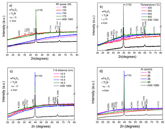
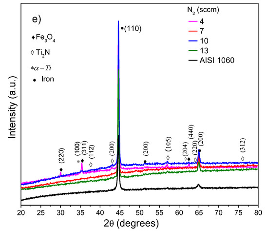
Figure 1.
XDR pattern of Ti/Ti2N films using five sets of parameters, and the parameter that varied was: (a) RF-power, (b) temperature on substrate, (c) distance target-substrate, (d) flow Ar gas, and (e) mass flow of N2.
3.2. Microstructure
3.2.1. Thickness and Morphology Analysis
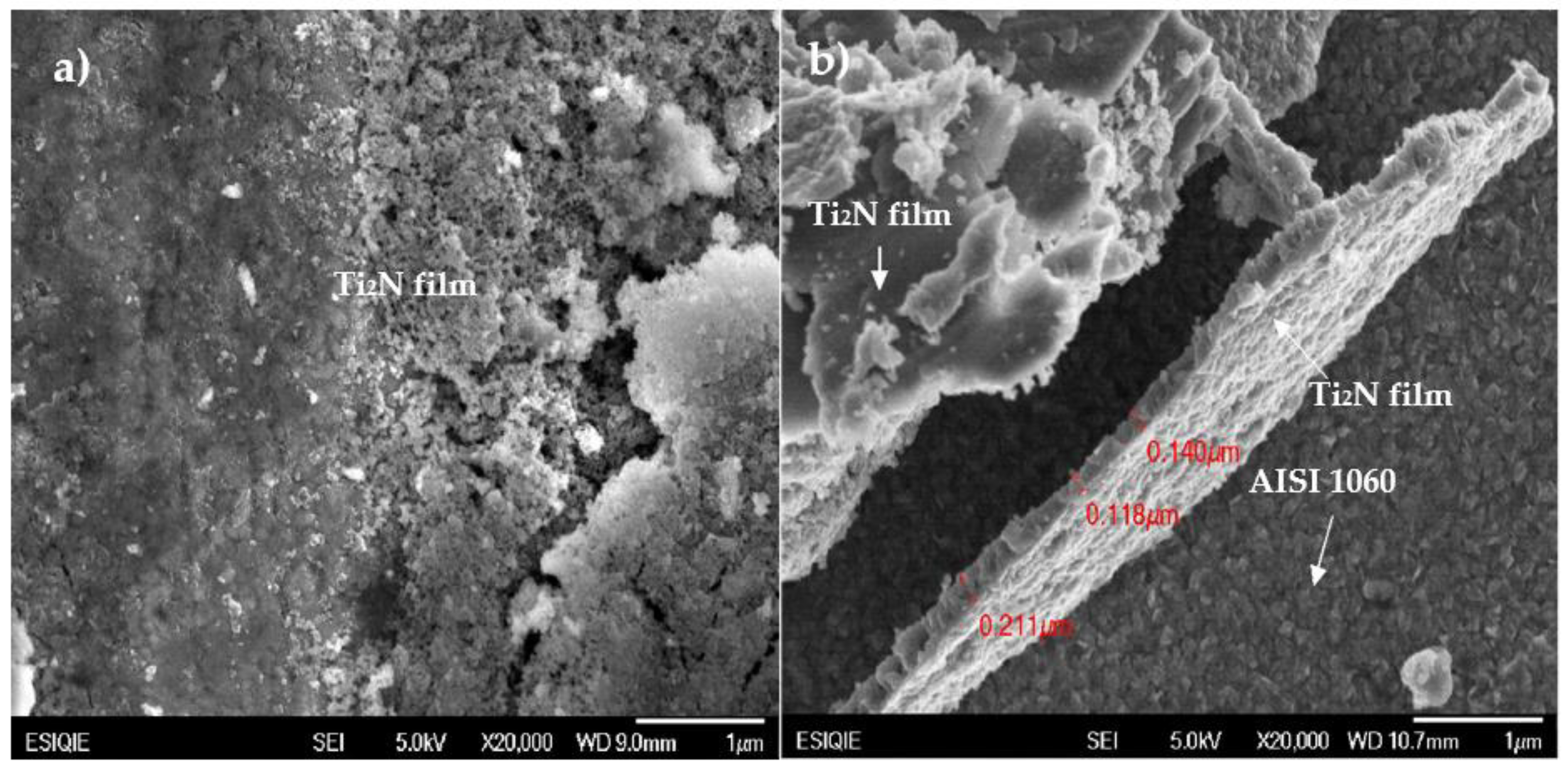
Figure 2a,b shows the surface morphology and cross-section of the Ti/Ti2N film, with the proposal to determine thickness, this film was deposited at 125 W, 450 °C, 16.5 cm and 46/7 ratio of Ar/N2. In Figure 2a can be observed that the surface morphology is not homogeneous, presenting two types of formations, according to Stranski–Krastanov or layer to island growth model where interface energy is comparable to island interaction energy [20]. First, it is possible to observe a zone grainy (dark sites) with moderate dome morphology, the high temperature favored the mobility of the adatoms, making the film denser and smoother, corresponding to Ti2N film [21]. However, the second zone (light sites) can be observed with fractionated particles and voids, like island growth promoted by presence of oxygen. The Ti ions form cluster material dispersed with carbon and nitrogen atoms [22]. Figure 2b shows intentionally damaged film to observe the cross-section and measure the thickness in Ti/Ti2N using SEM images. In cross-section image of Ti2N films shows square wedge-shaped dense columns. The value of thickness showed in Figure 2b is approximated because the cross section was not observed at a normal angle. The microstructure morphology of the substrate (AISI 1060) corresponds to high-density grains due to the austenite–martensite phases [23].
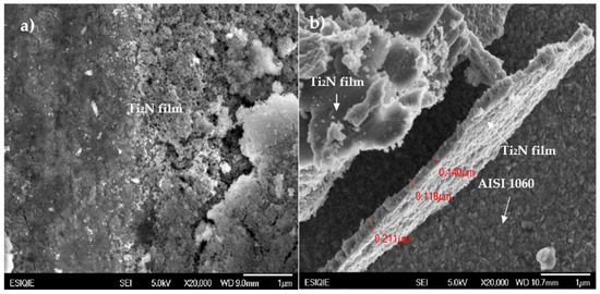
Figure 2.
Top-view (a) and cross-section (b) trace scanning electron microscope (SEM) images of Ti/Ti2N films.
3.3. Electrochemical Behavior of Ti2N Films
3.3.1. Potential Circuit Open Evaluation
Figure 3a–e shows the OCP evolution of Ti/Ti2N films deposited by RF magnetron Sputtering varying deposition conditions parameters in 3.5% NaCl solution. Figure 3a shows that the films of Ti/Ti2N obtained with the set 1 parameters, RF-175W, present a better performance than the substrate; thus, from the curves, it can be concluded that the tendency to corrode the substrate was reduced. In general, it shows a displacement of the potential, in which the most cathodic values are defined as when the RF-power decreases. This factor controls the target´s sputtering rate, increasing the energy of the system and achieving metastable states in the species where it can obtain this type of coatings; in addition, it can be indicated that the RF-power is a parameter that has effects on aspects of the coating that increase its resistance to corrosion products. Likewise, it can be observed that the RF-power at 175 W stabilizes the potential as a function of time; these results would demonstrate experimental evidence that the T2N layer formation does not take place at the expense of the Ti layer [24]. Regarding temperature (Figure 3b), the structures of the thin layers were investigated. It was determined that the structure of the layer could be expressed as a function of the ratio of the temperature of the substrate so that if it exceeded 400 °C, the potential at which these regions are exposed is characteristic of the reduced species. The amplitude of the reduction process and another allows the quantification of reduced corrosion products, so it is observed that in the ranges from 300 °C to 400 °C, the surface ratio of the samples determines uniformity in the coatings [25].
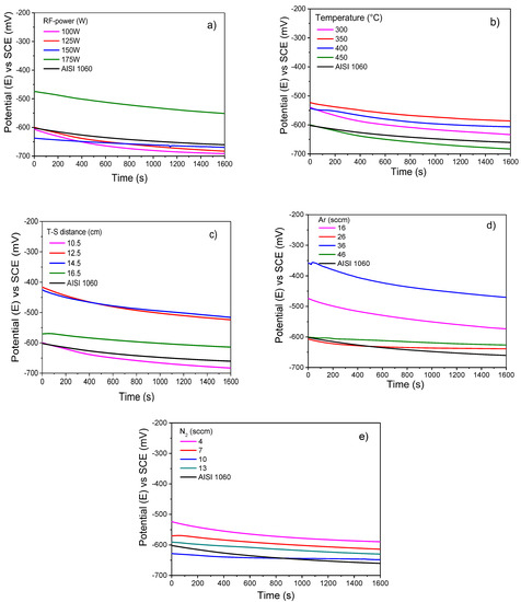
Figure 3.
Open circuit potential of Ti/TiN films in neutral 3.5 wt% NaCl solution at room conditions varying the following sputtering parameters: (a) RF-power, (b) temperature on the substrate, (c) target–substrate distance (d) argon flow mass, and (e) nitrogen flow mass.
The curves of 450 °C showed a similar tendency compared with the effect of RF-100 W, RF-125 W, and RF-150 W, and the titanium nitride showed a slightly less corrosion potential. Thus, the temperature ranges from 300 °C and 400 °C, promoting a stable layer that protects the metal against corrosive attack (the best stable parameters, see Table 2). As the values of the films obtained at 450 °C have a slight difference from the bare substrate, this indicates that it influences corrosion resistance very little, which can be attributed to the substrate temperature increases and the grain dimension. It also increases due to the higher critical dense columnar structure [26]. Figure 3c shows the curve corrosion potential of Ti/Ti2N films submerged in 3.5% salinity NaCl solution as electrolyte when the target-to-substrate distance was moved from 10.5, 12.5, 14.5, and 16.5 cm, keeping the constant 125 W, 450 °C, 16.5 cm and 46/7 ratio conditions Ar/N2. It observes that the curves corresponding to upper at 10.5 cm showed significant behavior compared with the bare substrate carbon steel and registered high voltage indicating the positive effect as a noble material, although presenting a low tendency in function at the exposure time 1600 s. This phenomenon is attributed to the distance between substrates, and the sputtering target was kept sufficiently close to ensure that the growing film was immersed in the sputtering stoichiometry plasma [27]. The film obtained from a 10.5 cm target-to-substrate distance exhibited a corrosion potential close to the non-coated carbon steel substrate. The potential corrosion test was the best, since its potential is the greatest compared to the examples evaluated using RF-power and temperature; it was thus decided to study the effect when the varied with the flow rate of Ar and N2 gasses, as shown in the Figure 3d,e. Figure 3d shows the potential corrosion tests conditioned by injecting a mass flow of Ar gas from 16, 26, 36, and 46 sccm submerged into NaCl 3.5% solution. This variable made it possible to uncover that the flow rate of Ar released must be low; thus, this reaction generated a passive layer. With these values, it is indicated that there was a brief or relative improvement concerning the bare carbon steel substrate with the Ar flux of 36 and 46 sccm. The increase of the gas flow rate allows the acceleration of the ionization process, promoting the increasing electron density of the plasma, due to the high-energy tail of the function being tied to electron energy distribution of the lower energies. Therefore, the direct ionization, which results from the energetic electron’s impact with gas atoms, is reduced, while the increasing electron density with the flow rate increases due to the stepwise ionization [28]. An interpretation of this fact is that the films achieve a structure with greater porosity when the flow increases. For lower movements, refined grains are obtained, achieving a diffuse and tortuous network for the electrolyte to reach the surface of the substrate, therefore increasing the corrosion protection in the presence of chloride ions. Instead, Figure 3e shows the potential with the variation of the N2 flow rate used as a deposition parameter during the sputtering process. It can be observed that the corrosion potentials curves are very similar, both in the behavior as a function of time and the average potential values; the system with an adequate performance compared to the substrate is 4 sccm. This performance is different from the one discovered by [29], who mentioned that the corrosion resistance under OCP conditions increased with increasing nitrogen concentration.

Table 2.
Fitting results of OCP curves with best behavior were immersed in 3.5% NaCl solution for 1600 s.
This result occurred was because the element managed to reduce the electrochemical potential; therefore, the potential difference between the substrate and the film decreased, and this resulted in the consequence of reducing the proclivity to galvanic corrosion. In summary, Ti2N film acts as a noble material and protection occurs due to the formation a protective oxide film. However, the other systems act as physical barriers between the corrosive species and the substrate. These phenomena can probably be attributed to the combination of sputtering parameters that can condition microstructure and promote the formation of a more stable film [30].
3.3.2. Potentiodynamic Polarization Curves Evaluation
Figure 4a–e shows the curves of the potentiodynamic polarizations of Ti/Ti2N films deposited on AISI 1060 steel, keeping the constant 125 W, 450 °C, 16.5 cm and 46/7 ratio conditions Ar/N2. In Figure 4a the results for the deposited films with the varying RF power are shown, and observing the curves, it can be concluded that the films in question have a similar corrosion resistance and are comparable with the substrate; the graphic of the result is identical, despite the film RF-175W exhibiting a few greater corrosion potentials. However, the current density values are in the same range, close to −2 mA/cm2; therefore, it is impossible to evaluate the films’ corrosion resistance using these parameters. Thus, all cases determined that the active region or zone is distinguished by general active dissolution, without the characteristics of potential for pitting or localized attack [31]. For this reason, the Ti2N film generates a protective layer that, when immersed in 3.5% solution NaCl, causes an increase in the open circuit potential with records increasing in current density. Subsequently, it stabilizes the current density as the potential increases to above 1000 mV. This behavior could be caused by a phenomenon called active dissolution [32]. The corrosion mechanism of Ti/Ti2N films is established by indicating that the thin layers have pores that allow the pass-through. The pores are generated during the deposition process; when they are exposed to the action of the electrolyte, new pores form in the Ti2N layers and these are removed. However, as the Ti2N films have a thickness of 156 ± 0.049 nm, the electrolyte takes longer to dissolve the Ti2N films. Therefore, they are more resistant to corrosion. This resistance is due to a layer of oxides and oxynitrides that retards the action of the electrolyte [32]. Figure 4b presents the results of the potentiodynamic polarization test for the Ti2N deposited under varying temperatures. It can be concluded by observing the curves that the best behavior in corrosion potential is obtained at 350° and 400 °C (see Table 3). In addition, the lower corrosion current density corresponded to the film deposited at 350 °C, the measured value was −2.5 mA/cm2 compared with the substrate, while a value of −2 mA/cm2 was registered. This value is like that generated for the film obtained at a temperature of 450 °C, but this value has the potential to be more anodic than the substrate; thus, they are converters in a sacrificial anode film, as is attributable to a partially protective film. Therefore, the films obtained at 300 °C, 350 °C, and 400 °C show better results in the potentiodynamic polarization tests, and this is due to their structure being dense and compact. The film obtained at 450 °C is a columnar type, and the result can be supported by the XRD spectra, since it can be seen in the peak of the spectrum that the temperatures between 300 °C and 400 °C have a smaller grain size and are more significant than the system at 450 °C. Therefore, these films, excepting the 450 °C film, offer better protection to the electrolyte and work inertly with the fixed cathodic potential so that the samples do not deteriorate, allowing the rate of deterioration to fall. Consequently, this reaction generated a passive layer caused by oxide Ti, a diffuse lattice for the electrolyte to reach the surface of the substrate [32].
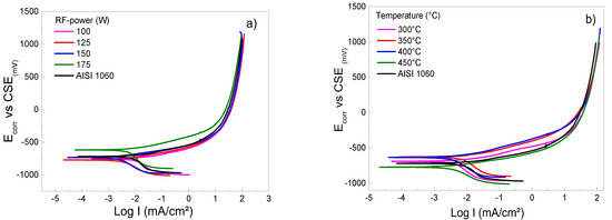
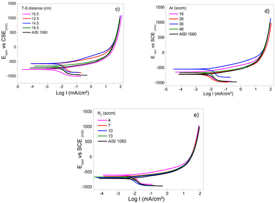
Figure 4.
Cyclic potentiodynamic curves of coated and uncoated AISI 1060 samples in 3.5 wt% NaCl solution at room conditions varying the following sputtering parameters: (a) RF-power, (b) temperature on substrate, (c) target–substrate distance, (d) argon flow mass, and (e) nitrogen flow mass.

Table 3.
Fitting results of potentiodynamic polarization curves with the best behavior immersed in 3.5% NaCl solution.
Figure 4c shows a displacement of potential in the potentiodynamic polarization curves. It indicates a shift to more cathodic values when increasing the target-to-substrate. For distances superior to 10.5 cm, an increase in the particle collisions allow the scattering and diminishing energy of atoms from the target to the substrate [33]. The increase of distance influences the porosity of the film; similarly, in the crystallinity, the texture is a characteristic observed using SEM and XRD, also found by [33]. This performance is associated with a layer in the Ti2N products’ formation and prevents corrosion. Likewise, it can be observed that the potentiodynamic polarization dynamic curves decrease the corrosion density. These results provide experimental evidence that the formation of the protective layer is independent of the corrosion potential since the corrosion density is reduced, which can be interpreted as an increase in corrosion resistance. Figure 4d shows the varying differences of the the Ar in the mass flow rates of 16, 26, 36, and 46 sccm. The graphic shows that the flow at 36 sccm achieved the best performance corrosion potential and density current when the flux was increased. There is little literature that refers to the effect of Ar gas on the electrochemical properties of Ti2N films. However, as is the case with many materials, the current density is linearly dependent on the external electric field. Likewise, as can be seen in [34], research work has investigated the influence of argon gas flow and found that the resistivity of Ti2N films increases with the argon gas flow [35]. According to [24], a high resistivity on film is due to the porous structure of the layer (the presence of voids between needles or columns). Finally, Figure 4e shows the range of the rate of flow from 4, 7, 10, and 13 sccm during the deposition process by RF–magnetron sputtering. It observes the formation of the Ti2N film, increasing the crystalline phase previously identified by XRD. It evaluates the range in which a Ti2N compound can be formed on the substrate, thus obtaining the deposition of layers whose properties depend on the chamber during the process. In addition, when the presence of nitrogen gas acting reactively in the chamber is abundant, it can cause the compound to form on the cathode, thus modifying the characteristics of discharge and deposition; this behavior is associated with obtaining 10-sccm N2. Therefore, a mixture of two types of gas with different concentrations is required to determine the range of Ar gas. In contrast, using gas as an inert substance is possible from 16 to 36 sccm, and the proportion of N2 is resolute between 4 and 7 sccm, where the XRD spectra determined that they have an appropriate stoichiometry on the deposited layer due to the greater effectiveness of the sputtering process [36]. The ratio gas mixture of Ar/N2 (36/4) results in the formation of dense films free of defects and residual stress, indicating an improvement in corrosion resistance [37].
3.3.3. Bode Diagram Evaluation
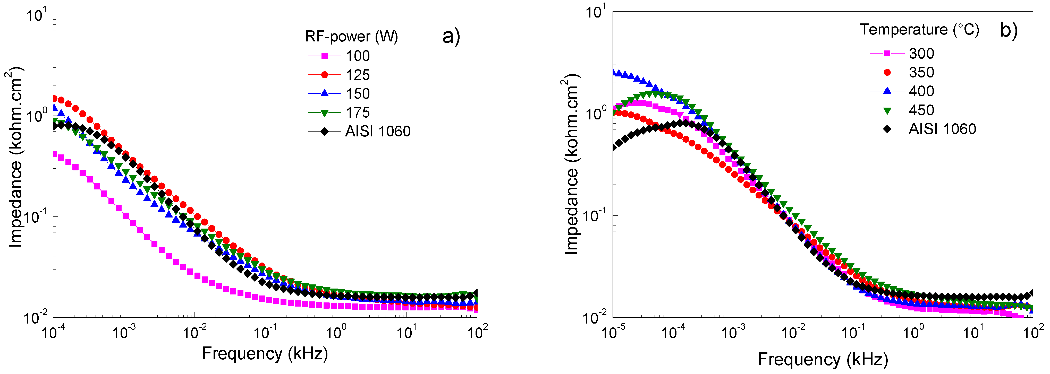
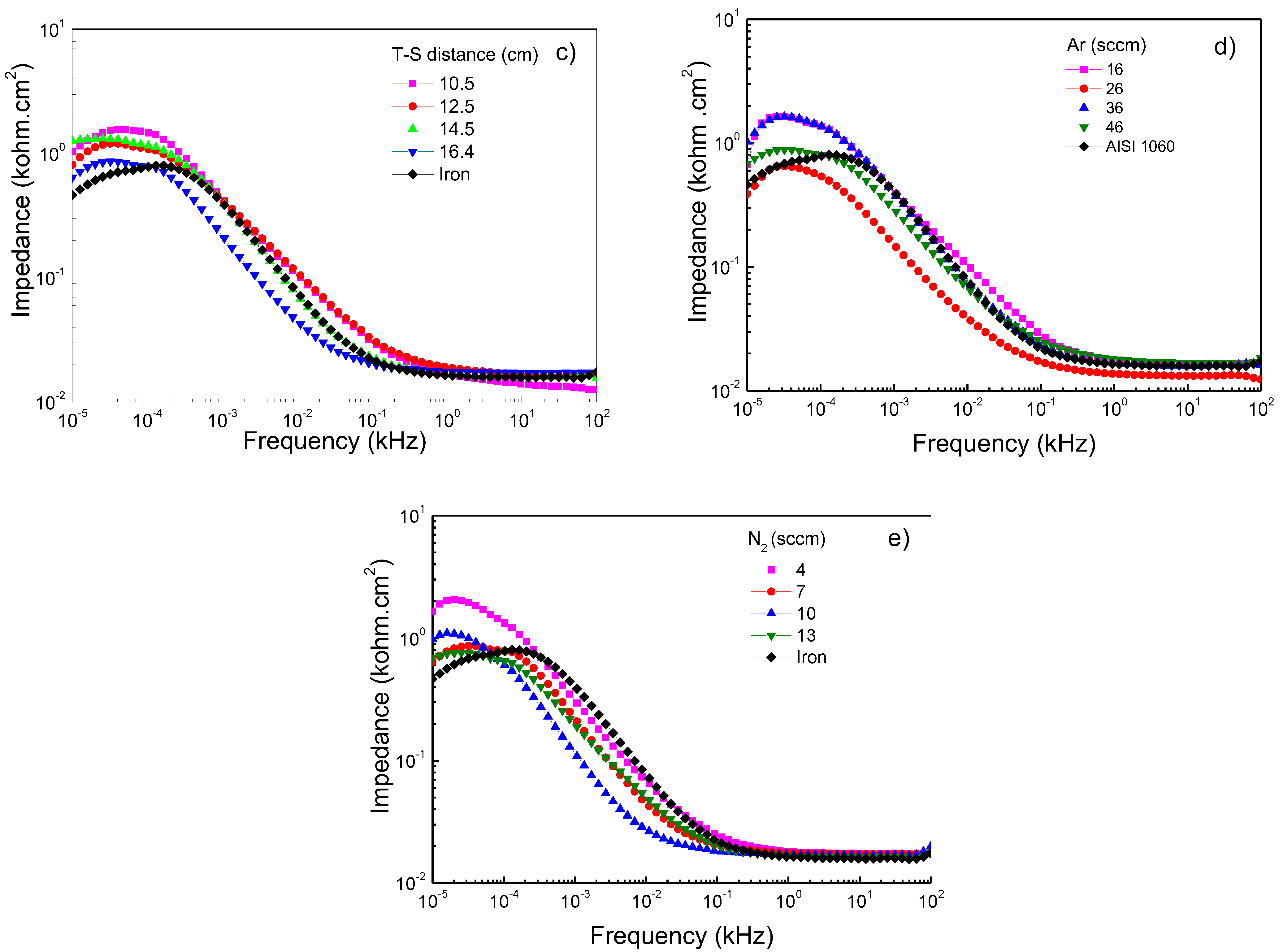
Figure 5a–e shows Bode plots of Ti/Ti2N deposited on AISI 1060, adjusting for different deposition parameters, keeping the constant 125 W, 450 °C, 16.5 cm, and 46/7 ratio conditions of Ar/N2. Figure 5a shows that the frequencies are specified at low and high values. The diagram shows the range from 10 × 104 to 10 × 101 Hz of the impedance modulus versus frequency; the presence of a horizontal plateau is related to the resistive elements and is associated with the interaction of the film when in contact with the NaCl solution. This electrolyte resistance and charge transfer values are similar between films and substrates. At frequencies between 0.26 and 0.01 Hz, the formation of the protective layers is exhibited in films that were sputtered with the RF-powers of 125 W and 175 W. However, the film sputtered at 100 W represents the protection layer’s breakdown due to the possible ingress of electrolytes and the consequent dissolution of the film. Figure 5b shows the films deposited on AISI 1060 integrating a Ti buffer layer first and, subsequently, the layer of Ti2N. When this film system was subjected to high and low corrosion frequency tests, the electrolyte impedance on the substrate was similar to the film; however, when the temperature of the substrate reaches 400 °C, the impedance value increases (see Table 4). However, it can be observed that when the temperature in the substrate increases, the impedance value decreases, probably attributed to the change of microstructure from the dense structure to the island type with huge pores present in the grains [38]. Figure 5c shows the Bode diagram corresponding to carbon steel and the variations of the deposition parameters, such as target-to-substrate distance. It observes that at high frequency the films present a similar value to above the substrate; thus, the corrosion resistance is not significant, and the target-to-distance does not directly relate to the impedance. This performance indicates that the protect film generated for the Ti2N film and the oxide on the substrate have a similar response due to the porous layer’s clogging generating protection [39]. At low frequency the films demonstrate a good behavior due to an increase in all the films’ impedance compared to the substrate; therefore, it is important that there is no alteration between Ti2N film and interface generated by the titanium when it is submitted to electrolyte attack. A low frequency can determine a behavior difference because the layer less target-to-substrate has a significant impedance. However, a low frequency of 0.01 Hz shows a decreased impedance associated with the dissolution and interconnection of porous and a decrease in corrosion resistance [40]. This behavior contrasts with the reported by the authors of reference [41], who postulated that “the high impedance values in the low-frequency region can be associated with the presence of the barrier layer of the passive film”. Figure 5d,e shows how the impedance in function changes of the flow rates of N2 and Ar gas, showing how the impedance in function changes with the flow rates of N2 and Ar gas. These systems observe that the response’s high frequencies are similar to those obtained when the temperature, RF-power and target-to-distance vary. This impedance behavior is due to the corrosion generated by the porosity of Ti2N films. Concerning low frequencies, a slight increase in the impedance to flow rate of 36 sccm is presented. However, the best flow rate of N2 is 4 sccm and, therefore, a better relationship between N2/Ar gas is the ratio of 4:16 sccm, allowing the optimization and reducing degradation, generating the possibility of the formation of corrosion products, which, when evaluated at high frequencies, clog the pores, and generate an increase in the resistive path [42].
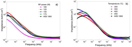
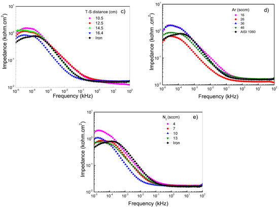
Figure 5.
Bode plots of Ti/Ti2N of coated and uncoated AISI 1060 samples in 3.5 wt% NaCl solution at room conditions varying the following sputtering parameters: (a) RF-power, (b) temperature on substrate, (c) target–substrate distance, (d) argon flow mass, and (e) nitrogen flow mass.

Table 4.
Fitting results of EIS curves with the best behavior immersed in 3.5% NaCl solution.
4. Conclusions
The research aims to optimize the deposition parameter to understand the level of influence of each variable. The study considered the following variables: RF-power, the substrate temperature, target-to-substrate distance, and the flow rate of N2 and Ar gas. The results found are as follows:
XRD analysis shows that the injection of less flow mass of N2 best influenced the structural property, allowing the lowest increase in the peak of Ti2N on the plane (112) tetragonal structure crystalline due to the nonstoichiometric of titanium nitride. In some samples diffraction peak reflections of Fe3O4 were found, which were formed after the polish was not eliminated by a plasma cleaning. The SEM analysis demonstrated the formation of nucleation growth, according to the Stranskis–Krastanov model (layer + island). In the OCP evaluation, the best behavior corresponded with a temperature of 350 °C. Additionally, in the potentiodynamic curves result, the substrate temperature of 400 °C was better than the other varying deposition parameters. Finally, the Bode analysis of EIS results shows the same relationship found with potentiodynamic tests with respect to the substrate temperature.
Author Contributions
Conceptualization E.O.-B. and A.G.-H.; methodology E.O.-B.; software, E.O.-B.; validation, W.A. and A.G.-H.; formal analysis, M.F. and A.G.-H.; resources, E.O.-B., M.F. and A.G.-H.; data curation, A.G.-H., M.F. and E.O.-B.; writing—original draft preparation, A.G.-H., M.F. and E.O.-B.; writing—review and editing, A.G.-H., F.G.-S. and J.E.B.; visualization, A.G.-H., E.O.-B. and M.F.; supervision, E.O.-B., M.F. and A.G.-H.; project administration, A.G.-H. and R.B.-G.; funding acquisition, A.G.-H. and E.O.-B. All authors have read and agreed to the published version of the manuscript.
Funding
This research was funded by the Consejo Nacional de Ciencia y Tecnología (CONACYT), and the fellowship for Ph.D. studies in material science at the Tecnológico Nacional de México/Instituto Tecnológico de Ciudad Madero.
Institutional Review Board Statement
Not applicable.
Informed Consent Statement
Not applicable.
Data Availability Statement
Not applicable.
Acknowledgments
Andrés González-Hernández is grateful to CONACYT for its support. The authors are also appreciative to Dominguez-Crespo, M.A. (Instituto Politécnico Nacional, CICATA-Altamira) and Dorantes-Rosales, H.J. (Instituto Politécnico Nacional, SEPI-ESIQIE) for their support on XRD and SEM analyses, respectively. W. Aperador acknowledges the Vicerrectoria de Investigaciones Universidad Militar Nueva Granada through the INV_ING_3123 project.
Conflicts of Interest
The authors declare no conflict of interest.
References
- Atkinson, H.V. Structural and functional materials. In Materials Science and Engineering Vol. II Encyclopedia of Life Support Systems (EOLSS); University of Sheffield: Sheffield, UK, 2002; Available online: www.eolss.net/sample-chapters/c05/e6-36-02-00.pdf (accessed on 28 September 2021).
- Hosseini, A.; Kishawy, H.A. Cutting tool materials and tool wear. In Machining of Titanium Alloys. Materials Forming, Machining and Tribology; Davim, J.P., Ed.; Springer: Berlin/Heidelberg, Germany, 2014; pp. 31–56. ISBN 978-3-662-43901-2. [Google Scholar] [CrossRef]
- Budinski, K.G. Overview of Surface Engineering and Wear. In Effect of Surface Coatings and Treatments on Wear; Bahadur, S., Ed.; ASTM International: West Conshohocken, PA, USA, 1996; pp. 4–21. [Google Scholar] [CrossRef]
- Broqvist, N.; Hogmark, S.; Medvedevaa, A.; Gunnarsson, S. On wear resistance of tool steel. J. Manuf. Process. 2012, 14, 195–198. [Google Scholar] [CrossRef]
- Gorozyca, F.E. Application of Metal Cutting Theory; Editor Industrial Press Inc.: New York, NY, USA, 1987; p. 98. ISBN 0831111763/9780831111762. [Google Scholar]
- Bayer, A.M.; Becherer, B.A. High Speed Tool Steels. In ASM Handbook; Machining ASM Handbook Committee: Geauga, OH, USA, 1989; Volume 16, pp. 51–59. [Google Scholar] [CrossRef]
- Isakov, E. Cutting Data for Turning of Steel; Industrial Press Inc.: New York, NY, USA, 2007; p. 137. ISBN 9780831133146. [Google Scholar]
- Miltiadis, A.B. (Ed.) Manufacturing Processes and Materials: Exercises; Boboulus & Ventus Publishing ApS: Telluride, CO, USA, 2010; p. 21. ISBN 978-87-7681-695-7. Available online: http://www.iqytechnicalcollege.com/ME%20205%20Manufacturing%20Processes-and-Materials.pdf (accessed on 28 September 2021).
- Zetek, M.; Zetková, I. Increasing of the Cutting Tool Efficiency from Tool Steel by Using Fluidization Method. Procedia Eng. 2015, 100, 912–917. [Google Scholar] [CrossRef][Green Version]
- Balasubramanyam, N.; Prasanthi, S.G.; Yugandhar, M. Study of Coated TiN and TiC on Cutting Tools for the PVD and CVD Coated Tungsten Carbide by Sand Blasting Pretreatment of Nickel and Carbon. Int. J. Adv. Sci. Eng. Inf. Technol. 2015, 75, 51–58. [Google Scholar] [CrossRef]
- Morosanu, C.E. Thin Films by Chemical Vapor Deposition, 1st ed.; Elsevier: Amsterdam, The Netherlands, 1990; Volume 7, p. 19. [Google Scholar] [CrossRef]
- Luzhao, S.; Guowen, Y.; Libo, G.; Jieun, Y.; Manish, C.; Meysam, H.G.; Karen, K.G.; Yong, S.C.; Byung, H.H.; Zhongfan, L. Chemical vapour deposition. Nat. Rev. Methods Primers 2021, 5, 1. [Google Scholar] [CrossRef]
- Xilling, L.; Zhi, Y. Effects of sputtering conditions on the structure and magnetic properties of Ni–Fe films. Mater. Sci. Eng. B Solid-State Mater. Adv. Technol. 2004, 106, 41–45. [Google Scholar] [CrossRef]
- ASTM G1-03; Standard Practice for Preparing, Cleaning, and Evaluating Corrosion Test Specimen. ASM International: Geauga, OH, USA, 2011. Available online: https://www.asminternational.org/home/-/journal_content/56/33542825/358486/PUBLICATION-STANDARD-TEMPLATE (accessed on 21 September 2021).
- Pauzon, C.; Markströ, A.; Dubiez-Le Goff, S.; Hryha, E. Efect of the process atmosphere composition on alloy 718 produced by laser powder bed fusion. Metals 2021, 11, 1254. [Google Scholar] [CrossRef]
- Sjahrul, M.; Maming, H.M. Use of sodium silicate from rice husk ash basic materials for coating electolytes in the synthesis of magnetite nanoparticles. RJSITM 2013, 3, 46–56. [Google Scholar]
- Huang, C.H.; Yoshimura, M. Direct ceramic coating of calcium phosphate doped with strontium via reactive growing integration layer method on α-Ti alloy. Sci. Rep. 2020, 10, 10602. [Google Scholar] [CrossRef]
- Maleki, E.; Unal, O.; Kashyzadeh, K.R. Efficiency Analysis of Shot Peening Parameters on Variations of Hardness, Grain Size and Residual Stress via Taguchi Approach. Met. Mater. Int. 2019, 25, 1436–1447. [Google Scholar] [CrossRef]
- Schwandt, C.; Fray, D.J. The Electrochemical Reduction of Chromium Sesquioxide in Molten Calcium Chloride under Cathodic Potential Control. Z. Nat. A 2007, 62, 655–670. [Google Scholar] [CrossRef]
- Benning, L.G.; Waychunas, G.A. Nucleation, Growth, and Aggregation of Mineral Phases: Mechanisms and Kinetic Controls. In Kinetics of Water-Rock Interaction; Brantley, S., Kubicki, J., White, A., Eds.; Springer: New York, NY, USA, 2008; Chapter 7; pp. 1–77. [Google Scholar] [CrossRef]
- Mortalò, C.; Deambrosis, S.M.; Montagner, F.; Zin, V.; Fabrizio, M.; Pasquali, L.; Capelli, R.; Montecchi, M.; Miorin, E. Production Strategies of TiNx Coatings via Reactive High Power Impulse Magnetron Sputtering for Selective H2 Separation. Membranes 2021, 11, 360. [Google Scholar] [CrossRef] [PubMed]
- Wu, T.; Blawert, C.; Serdechova, M.; Karlova, P.; Dovzhenko, G.; Wieland, F.; Zheludkevich, M.L. Role of polymorph microstructure of Ti6Al4V alloy on PEO coating formation in phosphate electrolyte. Surf. Coat. Technol. 2021, 428, 127890. [Google Scholar] [CrossRef]
- Wang, P.; Li, Z.; Lin, G.; Zhou, S.; Yang, C.; Yong, Q. Influence of Vanadium on the Microstructure and Mechanical Properties of Medium-Carbon Steels for Wheels. Metals 2018, 8, 978. [Google Scholar] [CrossRef]
- Korusenko, P.M.; Nesov, S.N.; Povoroznyuk, S.N.; Orlov, P.V.; Korotaev, D.N.; Poleshchenko, K.N. Chemical Composition and Mechanical Properties of Coatings Based on TiN Formed Using a Condensation with Ion Bombardment. Prot. Met. Phys. Chem. Surf. 2020, 56, 539–548. [Google Scholar] [CrossRef]
- Sun, Y.; Bailey, R. Effect of applied cathodic potential on friction and wear behavior of CoCrMo alloy in NaCl solution. Lubricantes 2020, 8, 2–15. [Google Scholar] [CrossRef]
- Zaki, A. Principles of Corrosion Engineering and Corrosion Control. In Cathodic Protectionn; Butterworth-Heinemann: Oxford, UK, 2006; Chapter 5; pp. 271–351. ISBN 9780750659246. [Google Scholar] [CrossRef]
- Ren, Y.; Jian, C.; Yaqing, C.; Jianlin, C.; Wei, Q. Effects of Substrate Temperature on the Corrosion Behaviour of Nanochromium Coatings Deposited by Direct Current Magnetron Sputtering. J. Nanomater. 2016, 2016, 4894062. [Google Scholar] [CrossRef]
- García-Valenzuela, A.; Fakhfouri, A.; Oliva-Ramírez, M.; Rico-Gavira, V.; Rojas, T.C.; Alvarez, R.; Menzel, S.B.; Palmero, A.; Winkler, A.; González-Elipe, R.A. Patterning and control of the nanostructure in plasma thin films with acoustic waves: Mechanical vs. electrical polarization effects. Mater. Horiz. 2021, 8, 515–524. [Google Scholar] [CrossRef]
- Shu, R.; Paschalidou, E.-M.; Rao, S.G.; Boyd, B.B.R.; Moro, M.V.; Primetzhofer, D.; Greczynski, G.; Nyholm, L.; Febvrier, A.L.; Eklund, P. Effect of nitrogen content on microstructure and corrosion resistance of sputter-deposited multicomponent (TiNbZrTa)Nx films. Surf. Coat. Technol. 2020, 404, 126485. [Google Scholar] [CrossRef]
- Hashim, I.H.; Aadim, K.A.; Ali, M.R. Effect of gas flow rate on plasma temperature and electron density of atmospheric argon plasma jet. Iraqi J. Phys. 2017, 15, 1117–1124. [Google Scholar]
- Shri, D.N.A.; Tsuchiya, K.; Yamamoto, A. Corrosion behavior of HPT-deformed TiNi alloys in cell culture medium. In Proceedings of the 4th International Conference on the Advancement of Materials and Nanotechnology (ICAMN IV 2016) AIP, Langkawi, Malaysia, 9–11 November 2016; AIP Publishing: College Park, MD, USA, 2016. No. 1877. ISBN 978-0-7354-1557-7. [Google Scholar] [CrossRef]
- Domínguez-Crespo, M.A.; Torres-Huerta, A.M.; Rodríguez, E.; González-Hernández, A.; Brachetti-Sibaja, S.B.; Dorantes-Rosales, H.J.; López-Oyama, A.B. Effect of deposition parameters on structural, mechanical, and electrochemical properties in Ti/TiN thin films on AISI 316L substrates produced by r. f. magnetron sputtering. J. Alloys Compd. 2018, 746, 688–698. [Google Scholar] [CrossRef]
- Hong-Ying, C.; Fu-Hsing, L. Oxidation behavior of titanium nitride films. J. Vac. Sci. Technol. A 2005, 23, 1006–1009. [Google Scholar] [CrossRef]
- Khojier, K.; Savaloni, H.; Shokrai, E.; Dehghani, Z.; Dehnavi, N.Z. Influence of argon gas flow on mechanical and electrical properties of sputtered titanium nitride thin films. J. Theor. Appl. Phys. 2013, 7, 2–6. [Google Scholar] [CrossRef]
- Yinghe, M.; Kexin, Z.; Jianguo, Y.; Xiubo, T.; Chunzhi, G.; Wenjian, Z.; Yanming, H.; Zengliang, G.; Lianfeng, W.; Chu, P.K. Effects of the target-to-substrate distance on the microstructure and properties of TiN coatings fabricated by pulse-enhanced vacuum arc evaporation. J. Adhes. Sci. Technol. 2021, 35, 1125–1137. [Google Scholar] [CrossRef]
- Freixas, J.; Eustache, E.; Roussel, P.; Brillard, C.; Deresmes, D.; Nuns, N.; Rolland, N.; Brousse, T.; Lethiena, C. Sputtered titanium nitride: A bifunctional material for Li-Ion Microbatteries. J. Electrochem. Soc. 2015, 162, A493–A500. [Google Scholar] [CrossRef]
- Kim, H.T.; Park, J.Y.; Park, C. Effects of nitrogen flow rate on titanium films deposition by DC facing target sputtering method. Korean J. Chem. Eng. 2012, 29, 676–679. [Google Scholar] [CrossRef]
- Grayeli, A.R.; Korpi, P.; Balshabadi, M.M.; Larijani, M.; Habibi, A.; Hamidi, A.; Malek, M. Effect of Gas Ratio on Tribological and Corrosion Properties of Ion Beam Sputter Deposited TiN Coatings. Prog. Color Colorants Coat. 2018, 11, 129–135. [Google Scholar] [CrossRef]
- Choudhary, R.K.; Mishra, P.; Roychowdhury, S.; Kain, V. Effect of substrate temperature and nitrogen concentration during sputtering on corrosion behaviour of AlN coatings. Trans. IMF Int. J. Surf. Eng. Coat. 2016, 94, 250–253. [Google Scholar] [CrossRef]
- Menghani, J.; Pai, K.B.; Totlani, M.K. Corrosion and wear behaviour of ZrN thin films. Mater. Surf. Interfaces 2011, 5, 122–128. [Google Scholar] [CrossRef]
- Fattah-Alhosseini, A.; Shoja, S.T.; Zebardast, B.H.; Samim, P.M. An Electrochemical Impedance Spectroscopic Study of the Passive State on AISI 304 Stainless Steel. Int. J. Electrochem. 2011, 2011, 8–16. [Google Scholar] [CrossRef]
- Babaeia, K.; Fattah-Alhosseinia, A.; Elmkhaha, H.; Ghomi, H. Surface characterization and electrochemical properties of tantalum nitride (TaN) nanostructured coatings produced by reactive DC magnetron sputtering. Surf. Interfaces 2020, 21, 100685. [Google Scholar] [CrossRef]
Publisher’s Note: MDPI stays neutral with regard to jurisdictional claims in published maps and institutional affiliations. |
© 2022 by the authors. Licensee MDPI, Basel, Switzerland. This article is an open access article distributed under the terms and conditions of the Creative Commons Attribution (CC BY) license (https://creativecommons.org/licenses/by/4.0/).


