Article

Corrosion Nature in [CoN/AlN]n Multilayers Obtained from Laser Ablation

1
Grupo de Investigación en Tribología, Polímeros, Metalurgia de Polvos y Transformaciones de Residuos Sólidos, Universidad del Valle, Cali 76001, Colombia
2
School of Engineering, Universidad Militar Nueva Granada, Bogotá 49300, Colombia
*
Author to whom correspondence should be addressed.
Metals 2021, 11(12), 2049; https://doi.org/10.3390/met11122049
Submission received: 14 October 2021 / Revised: 9 December 2021 / Accepted: 14 December 2021 / Published: 17 December 2021
(This article belongs to the Special Issue Corrosion and Surface Modification of Metallic Materials)

Abstract

:
The aim of this work is the improvement of the electrochemical behavior of industrial steel using [CoN/AlN]n multilayered system via reactive Pulsed Laser Deposition (PLD) technique with a Nd: YAG laser (λ = 1064 nm) on Silicon (100) and AISI 302 steel substrates. In this work was varied systematically the bilayer period (Λ) and the coatings were characterized by X-ray diffraction (XRD), Fourier transform infrared spectroscopy (FTIR), scanning electron microscopy (SEM), and the chemical composition was determined by means of X-ray photoelectron spectroscopy (XPS). The maximum corrosion resistance for the coating with (Λ) equal to 34.7 nm, corresponding to n = 30 bilayered. The polarization resistance and corrosion rate were around 7.62 × 10⁵ kOhm × cm2 and 7.25 × 10⁻⁵ mm/year, these values were 6.3 × 10⁵ and 78.6 times better than those showed by the uncoated 302 stainless steel substrate (1.2 kOhm × cm2 and 0.0057 mm/year), respectively. The improvement of the electrochemical behavior of the steel 302 coated with this [CoN/AlN]n can be attributed to the presence of several interfaces that act as obstacles for the inward and outward diffusions of Cl ions, generating an increment in the corrosion resistance. The electrochemical results found in the [CoN/AlN]n open a possibility of future applications in mechanical devices that require high demands in service conditions.

Graphical Abstract

1. Introduction

Many works have focused on the surface protection of mechanical devices manufactured in metals, which due to the operating and service conditions suffer some type of deterioration due to corrosion effect. In this sense, various processes to improve and coat the steels surfaces have been developed and applied successfully. However, some of the processes and materials applied are highly expensive, which limits their application on an industrial scale [1,2,3]. Therefore, new manufacturing processes have been developed with the interest of overcoming some technological limitations thus, today these technologies have become indispensable in most of the industrial sector, among which is the pulsed laser deposition technique (PLD). This technique makes it possible to reproduce almost any type of material with high stoichiometric reproducibility and versatility, at a significantly lower cost than current commercial equipment [4,5,6]. Taking in account the last information, the metal nitride coatings based on CoN and AlN have been studied and obtained by many deposition methods. So, in the case of CoN material, the processes that govern the incorporation of nitrogen in the films during atomic layer deposition (ALD) of cobalt and cobalt nitride system prepared from cobaltocene (CoCp2) and NH3 plasma are a rather complex. Therefore, is demonstrated that nitrogen incorporation is strongly temperature-dependent; at temperatures of 260 °C and below, the deposited films consist primarily of Co2N, whereas increasing the temperature to 300 °C leads to a mixture of Co3N and Co, and at 350 °C, nominally pure Co is obtained [5,6]. Moreover the stoichiometry can be adjusted by varying the nitrogen pressure, it being feasible to produce the nominal stoichiometries of Co2N, CoN and Co2N3. At higher pressures the stoichiometry seems to remain practically unchanging. PLD can be a very valuable method for depositing cobalt nitrides [3,7,8].
In the case of Aluminum nitride (AlN) films with different structural features were synthesized onto Si and steel substrates by pulsed laser deposition in vacuum and ambient nitrogen with different laser incident fluencies, and laser pulse frequencies, thus the results clearly shown a correlation between the films’ structure and the physical properties dependent on the experimental conditions [9,10]. Also, the electrochemical tests pointed to the fact that the protection of the stainless-steel (304L) and mild-steel substrates by AlN coatings is due to its insulating nature [11]. However, this protection is, to a great extent affected by the open porosity of the films that remains quite high, due to the corrosion of aluminum nitride (AlN) in aqueous solutions have been evaluated in situ, using an ammonium/ammonia ion-selective electrode. The corrosion behavior of AlN over a pH range of 5.5–12 indicates that the corrosion products that are formed act as a protective barrier layer in the pH regime where they have the lowest stability. An insoluble barrier layer is formed via the oxidation of the AlN surface in air at a temperature of 750 °C for 10 min [2,11]. Taking into account the above, various systems have been developed to improve the characteristics of the coatings, implementing multilayer systems, which in some conditions have presented significant improvements, however in multilayer systems deposited with AlN and CoN materials they have not yet been reported significant contributions of corrosion resistance [3,11]. Unfortunately, literature presents few research focused on studying the electrochemical properties of [CoN/AlN]n multilayer coatings under corrosive environments. However some authors [8,9,10,11], W. De La Cruz, and L. Lynne M. Svedberg [3,11] have studied the physical and electrochemical properties of steel substrates coated with CoN and AlN single layers, these studies do not relate the [CoN/AlN]n multilayer coating’s performance in corrosive environments. Therefore, the aim of this work was to study the electrochemical properties for [CoN/AlN]n multilayers coatings on AISI 302 stainless steel substrates in corrosive environments. Taking into account the last is possible find a application would focus on the industry for low dimensional devices such as PVC micro extrusion molds where there are wear phenomena due to the abrasive polyvinyl and corrosion phenomena due to the presence of the Cl ion. In this sense all the above is addressed to the protection of industrials steel devices which can be used n the metal-mechanic industry.

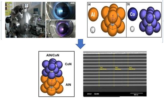
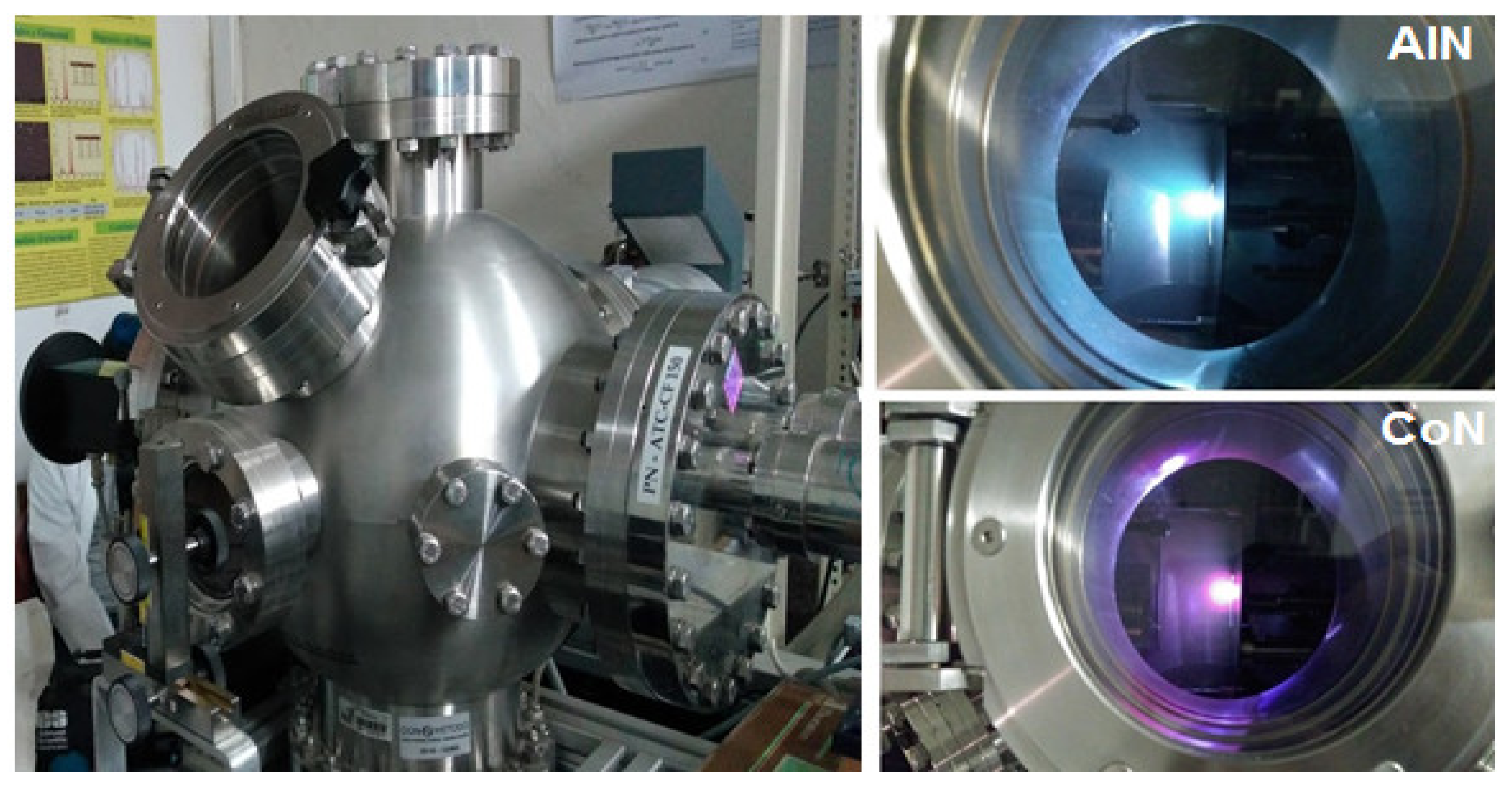
2. Materials and Methods

The single and multilayers coatings were grown from high purity aluminum (Al) and cobalt (Co) targets in a nitrogen environment. Silicon (100) substrates and AISI 302 steel disks substrates with a diameter of 19 mm and a thickness of 4 mm were used. The metallic substrates were prepared superficially by abrading with silicon carbide abrasive paper and were subsequently polished in wipes with 1 and 0.3 μm alumina until a specular finish was obtained. Finally, they were immersed in an acetone bath for subsequent cleaning with ultrasound. The ablation of the samples was performed inside a vacuum chamber equipped with a mechanical pump model ACP 28 (A & J Vacuum Services, Paris, France) with an evacuation rate of 140 L/s for pre-vacuum and an Alcatel turbo molecular pump (A & J Vacuum Services, Paris, France) with a pumping rate of 280 L/s for high vacuum (A & J Vacuum Services, Paris, France). The coatings were grown in a Nitrogen atmosphere (99.99% purity) at a constant pressure of 20 mTorr. Aluminum (Al) and cobalt (Co) disks with a 2.54 cm diameter and a 0.31 cm thickness were used as target material, which were rotated at a frequency of 2.2 Hz in order to avoid cratering and achieve high uniformity in the deposition. The deposition time was 60 min and each deposit consisted of 36.000 pulses, using a Nd: YAG laser model INDI-30 Spectra Physics (Quanta-Ray, Berlin, Germany) with a fundamental wavelength of 1064 nm at a repetition rate of 10 Hz and a laser fluence of 7 J/cm2 [12]. The energy of the laser pulses was 340 mJ, which impacted at an angle of 45° on the targets located at a distance of 5.4 cm from the substrates. All substrates were heated to a temperature of 300 °C which was kept constant during the deposition process. Figure 1 shows the schematic of the experimental setup of the layer deposition process.
The structural characterization was obtained by X-ray diffraction (XRD) with grazing incidence diffraction geometry, using a Philips-MRD diffractometer (Malvern Panalytical Ltd., London, UK) with Cu-Kα radiation, λ = 1.5406 Å, a scintillation detector using 0–20 performing setting, a sweep from 20 to 80 with a pitch of 0.01°, and a step time of 2 s. X-ray photoelectron spectroscopy (XPS) was employed to analyze the nitride materials in order to determine their chemical compositions and the bonding of the Aluminum, cobalt, and nitrogen, atoms using an ESCAPHI 5500 system (ESCA, Berlin, Germany) with monochromatic Al-Kα radiation and with an energy step of 0.1 eV. The surface sensitivity of this technique is very high and any contamination can produce deviations from the real chemical composition. Thus, exhaustive XPS studies were performed for the AlN and CoN coatings because XPS analysis is usually performed under ultrahigh vacuum conditions with a sputter cleaning source to partially remove undesired contaminants. Al is highly reactive so the XPS analysis was conducted in an ultra-high vacuum region (low pressure 1 × 10⁻⁹ mbar), which means that it was necessary to have sufficient time for recording the XPS spectra. The Fourier transform infrared (FTIR) analysis of the coatings was carried out with a Shimatzu 8000 spectrometer (Quanta-Ray, Brussels, Belgium), which uses a ceramic-type Nerst source in the range of 450–4000 cm−1 in transmission mode. The coating thicknesses, the multilayers’ modulation and the corrosion surfaces processes for all systems were determined by scanning electron microcopy (SEM) using a JSM 6490LV JEOL (JEOL, Tokyo, Japan) with an acceleration voltage of 20 keV, a tungsten filament and observation in backscattered electron mode. By using the CaRIne Crystallography 3.1 software (CaRIne Crystallography, S.B California, CA, USA), the crystalline structure simulation for the AlN and CoN layers was carried out. The electrochemical study was carried out with a Gamry unit, model PCI 4 (CaRIne Crystallography, Santa Barbara, CA, USA), utilized for DC and AC measurements. Electrochemical Impedance Spectroscopy (EIS), and Tafel polarization curves were obtained at room temperature, using a cell with a working electrode within an exposed area of 1 cm2, a reference electrode (Ag/AgCl) and a platinum wire counter-electrode under a 3.5% NaCl solution with distilled water. For Nyquist diagrams, was performed frequency sweep in the range from 100 kHz to 0.001 Hz using sinusoidal voltage amplitude of 10 mV applied to the working electrode (sample) and reference electrode. The samples were kept in the 3.5% NaCl aqueous solution for 30 min to establish a stable corrosion potential (Ecorr) values at which the EIS measurements were initiated. Taking to account that the experimental EIS parameters, particularly scan rate, will affect both initial and final potential after establishing a stable (Ecorr). To obtain Tafel polarization curve diagrams was carried out a voltage sweep at a speed of 0.5 mV/s in the range of −0.25 to 1.0 V.

3. Results

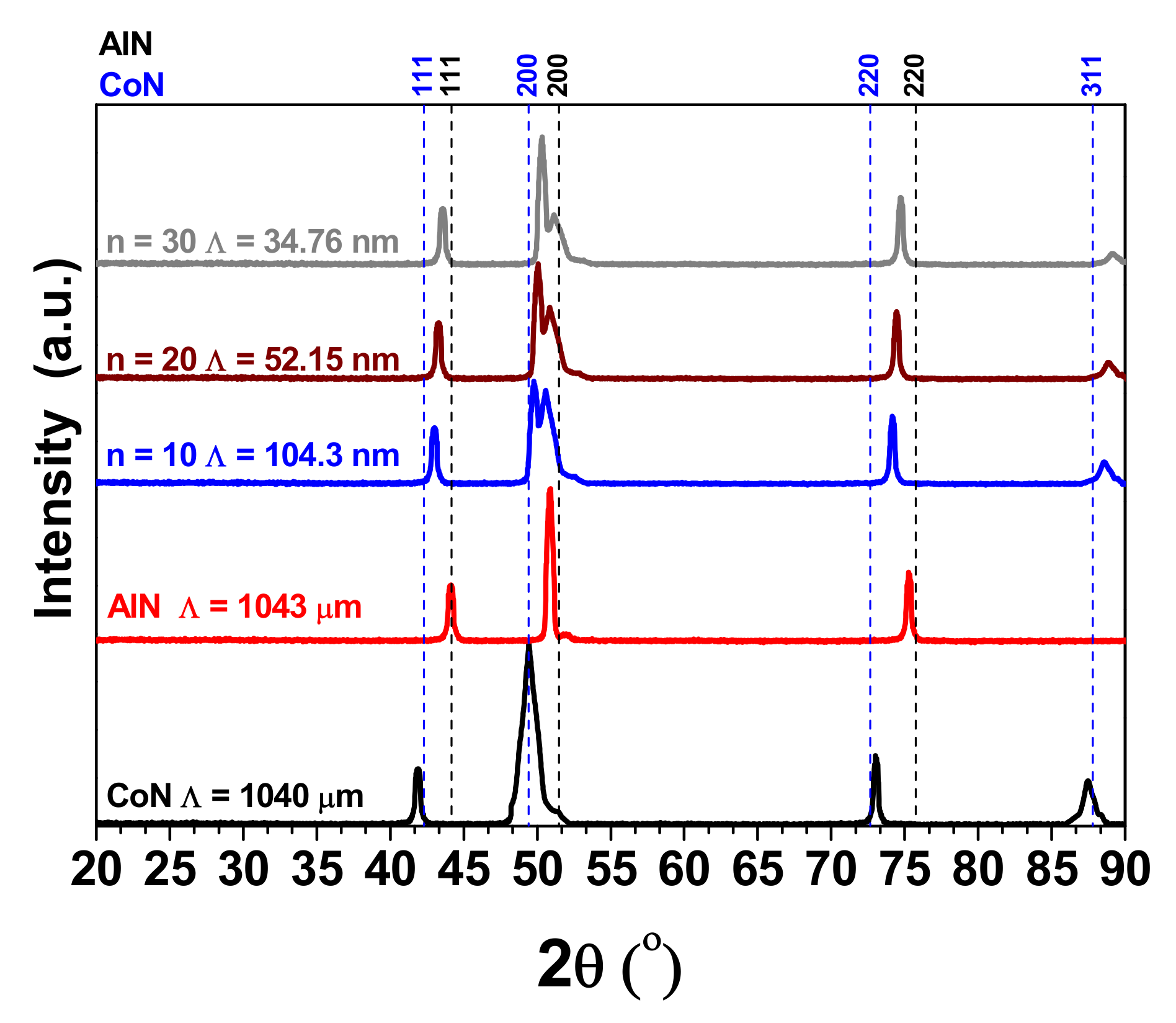
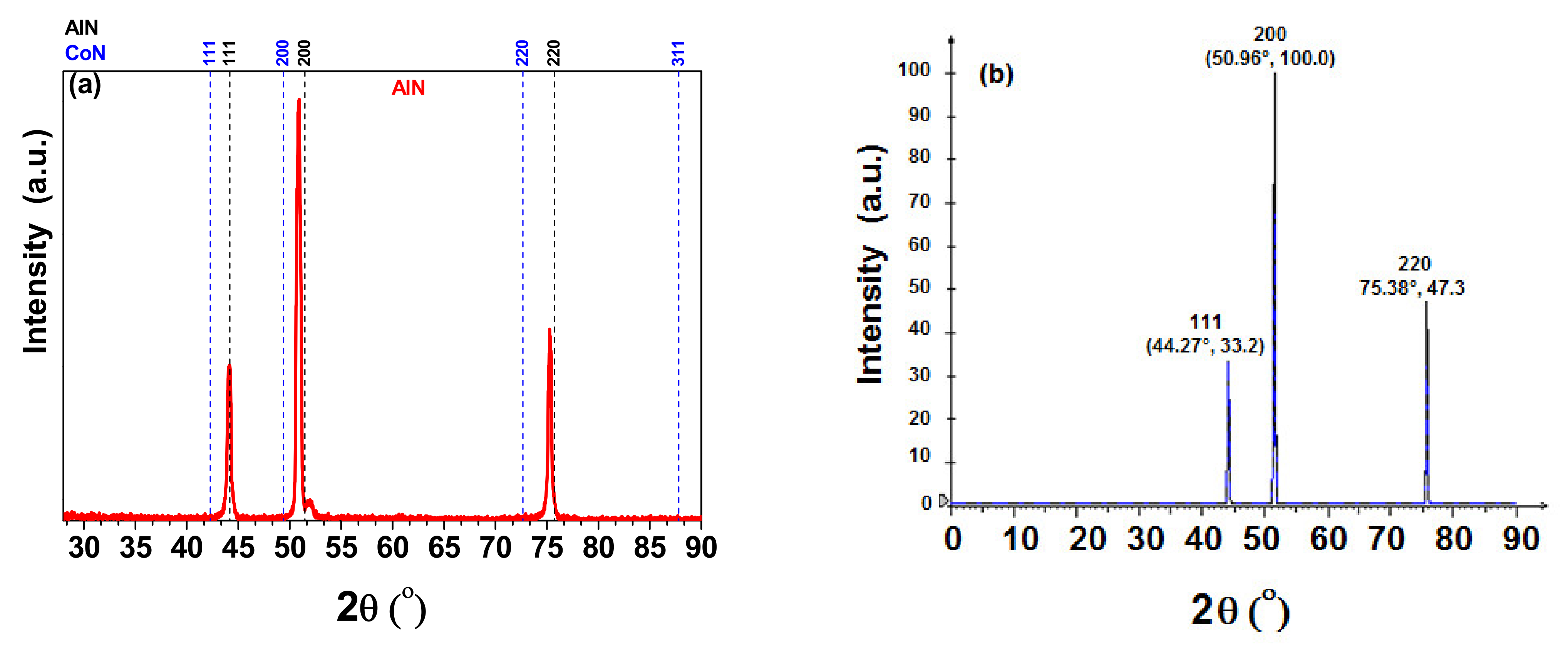
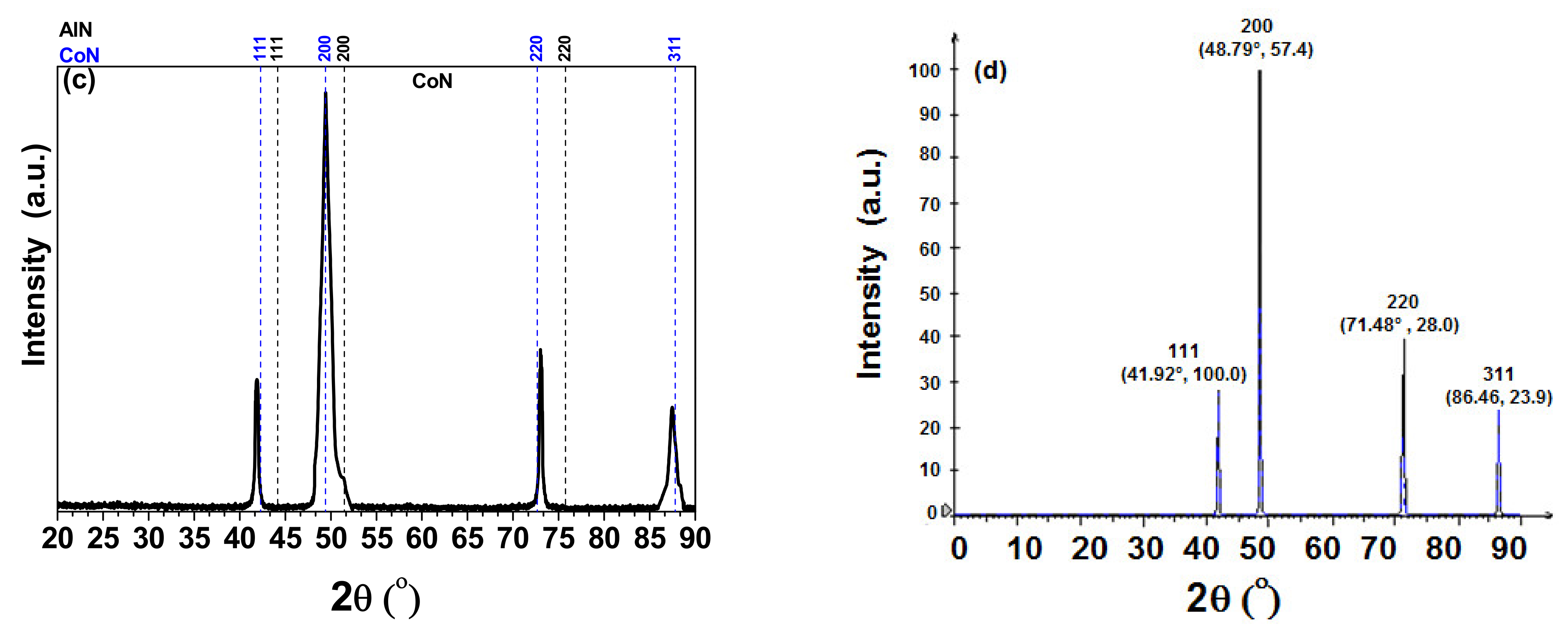
3.1. X-ray Difraction (XRD)

Figure 2 shows the diffraction patterns for the AlN, CoN coatings and for each of the [AlN/CoN]n multilayer systems deposited onto silicon (100) substrates, these patterns were obtained by X-ray diffraction in the grazing beam mode. In addition, Figure 2 shows that the AlN and CoN layers presented a NaCl-type face centered cubic structure FCC. The pattern obtained for the aluminum nitride (AlN) layer showed a strong preferential orientation in the (200) plane for 2ϴ = 50.86°, as well as the presence of very clear peaks for 2ϴ = 44.14° and 2ϴ = 75.26°, corresponding to AlN reflections in the (111) and (220) planes, respectively. The AlN structure exhibited Fm3m spatial symmetry according to the JCPDF 00-025-1495 database. From the diffractogram of the cobalt nitride (CoN) layer, it can be observed that a strong preferential orientation was exhibited in the (200) plane for 2ϴ = 49.23°, in addition to the presence of other observable peaks for values of 2ϴ = 41.88°, 72.94° and 87.46°, corresponding to CoN reflections in the (111), (220) and (311) planes, respectively. These are characteristic of a FCC structure which was observed for the AlN layer. In addition, the CoN exhibited F43m spatial symmetry according to JCPDF file 00-016-0116 [12,13,14,15].
Moreover, the XRD results can collect information from a space around the normal vector on the surface (from a cross-section) that related the crystallite size, so Table 1 shows the dependence of lateral crystallite size as a function of the increasing of bilayer numbers or reduction of bilayer periods. The crystallite size was determined by Scherrer formula [16]:
D v = K λ β c o s θ
where Dv is the weight volume crystallite size, K is the Scherrer constant, a arbitrary value that falls in the range of 0.87–1.0 many authors usually assume K = 1, λ is the wavelength of the radiation (1.5406 Å), β is the integral breadth of a reflection (in radians 2θ) and θ is the angle between the incident ray and the scattering planes. In this sense the Scherrer formula predicts the crystallite size with information collected from XRD results. In this work the information from AlN, CoN and [AlN/CoN]n coatings was used with preferential orientation in the Bragg plane (200). In Table 1 decrease of the lateral crystallite size is observed due to higher bilayer numbers generating lower bilayer thickness which affect the growth of crystallites within individual layers.

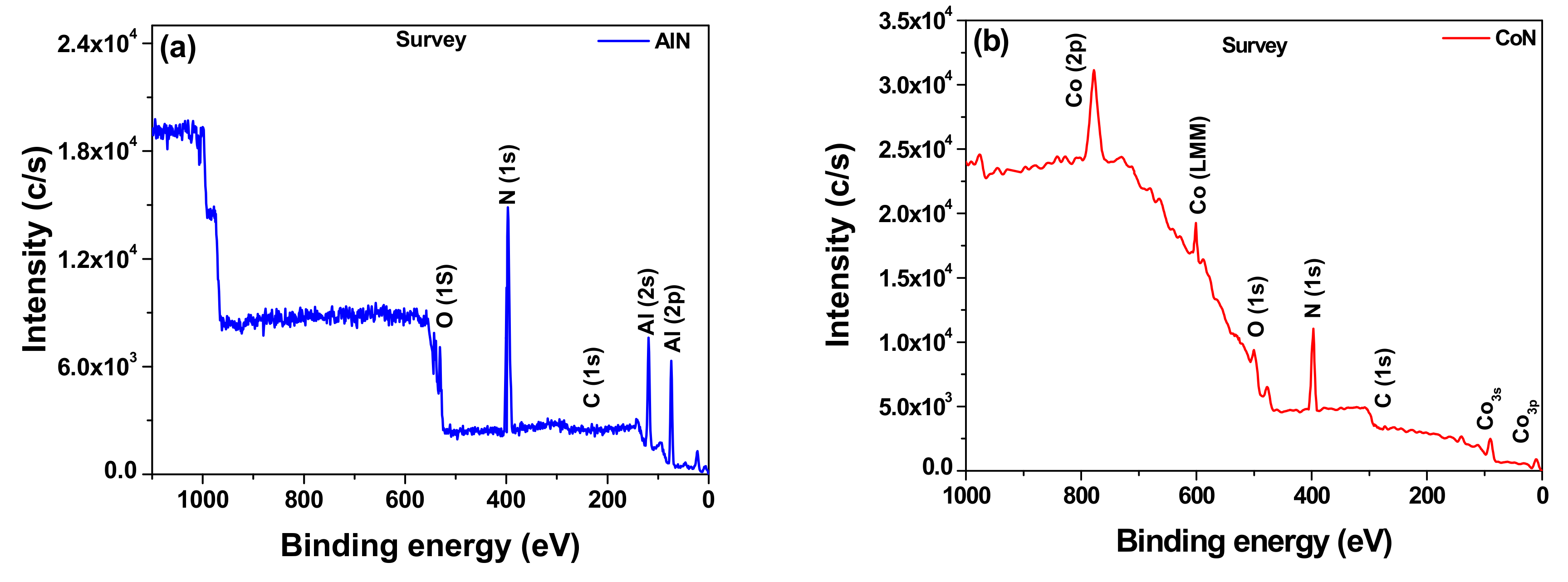
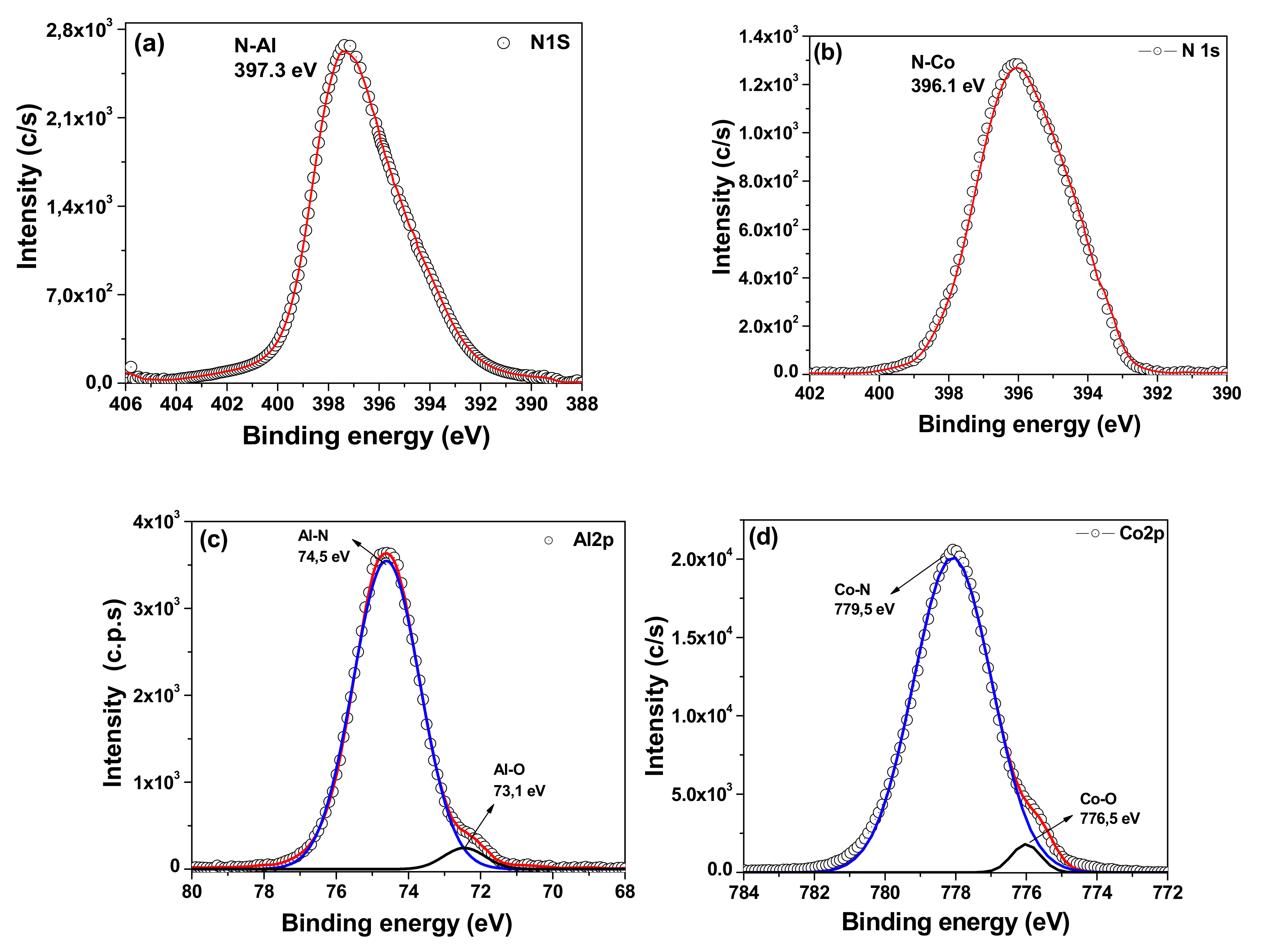
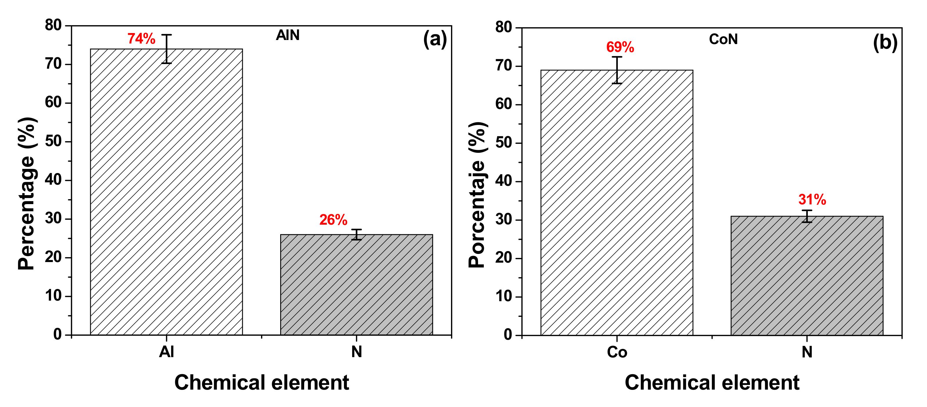
3.2. X-ray Photoelectron Spectroscopy (XPS)

From the X-ray photoelectron spectroscopy (XPS) technique, the information regarding the atomic bonds present in the different aluminum nitride and cobalt nitride layers was obtained (Figure 3a,b). In these spectra, the presence of the peaks located at 528.86 eV and 529.50 eV were observed for the AlN [17,18,19,20] and CoN [21,22,23] layers, respectively. These peaks correspond to the energies of the 1s bond of oxygen (O1s), which are associated with a possible slight contamination of the samples. These results present the N1s signal of the high-resolution XPS spectrum for the AlN and CoN layers, showing the nitrogen peak with 1s hybridization at 396.17 eV and 397.30 eV, characteristic of N-Al and N-Co bonds, respectively. Moreover it was possible to found the Al2p and Co2p signals corresponding to the AlN and CoN coatings, respectively. After performing the corresponding deconvolutions using Gaussian curves, two peaks were found for the aluminum nitride layer at 74.5 eV and 73.1 eV, characteristic of the signals for the Al-N and Al-O bonds; while for the cobalt nitride layer, peaks were found at 779.5 eV and 778.5 eV, characteristic of the signals for the Co-N and Co-O bonds [17,18,19,20,21,22,23]. In this sense, Table 2 present the elemental percentages according to the approximate stoichiometries of the metal-ceramic coatings based on transition metals associate to (Al74N26) layer and (Co69N31) layer. Therefore, the nonstiochiometry AlN (Al74N26) and CoN (Co69N31) coatings could be generated due to the N2 gas and laser fluence.
Figure 4a,b present the N1s signal of the high-resolution XPS spectrum for the AlN and CoN layers, showing the nitrogen peak with 1s hybridization at 396.17 eV and 397.30 eV, characteristic of N-Al [19,20,21,22,23] and N-Co [24,25,26] bonds, respectively. Figure 4c,d depict the Al2p and Co2p signals corresponding to the AlN and CoN coatings, respectively. After performing the respective deconvolutions using Gaussian curves, two peaks were found for the aluminum nitride layer at 74.5 eV and 73.1 eV, characteristic of the signals for the Al-N and Al-O bonds [20,21,22,23]; while for the cobalt nitride layer, peaks were found at 779.5 eV and 778.5 eV, characteristic of the signals for the Co-N and Co-O bonds [24,25,26]. Moreover, can be observed that the (C1s) signal represents lowest intensity which can indicate that the presence of AlC and CoC carbides is not evident (Figure 3).
Figure 5a,b present the elemental percentages according to the approximate stoichiometries of the metal-ceramic coatings based on transition metals. They were calculated for the aluminum nitride layer (Al74N26) with a stoichiometric ratio of 2.84 and for the cobalt nitride layer (Co69N31) with a stoichiometric ratio of 2.22. It can be observed that the stoichiometric ratio for both metal-ceramic coatings tends to saturate in the metal content, which is reflected in the electrochemical properties.

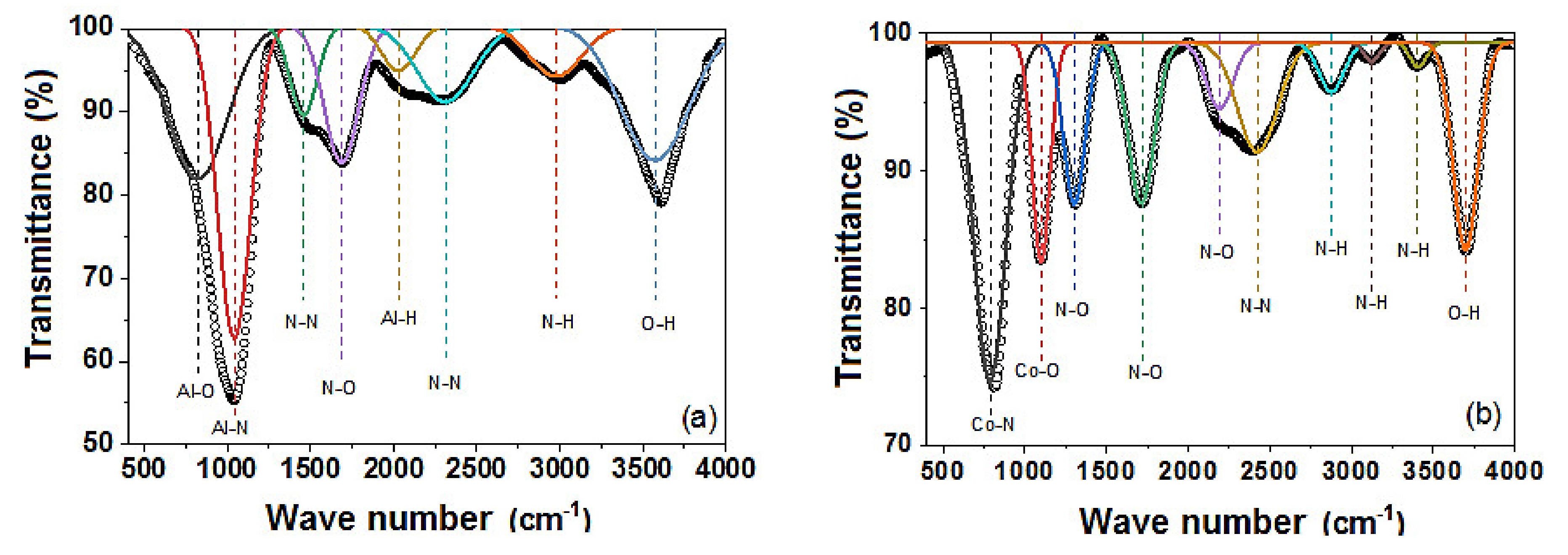
3.3. Fourier Transform Infrared Spectroscopy (FTIR)

Fourier transform infrared spectroscopy analysis was performed using attenuated total reflectance (ATR), in transmittance mode in order to observe the vibration modes associated with single layer coatings of aluminum nitride (AlN) and cobalt nitride (CoN) deposited on Si (100) substrate (Figure 6). From the FTIR spectra, the corresponding deconvolutions were performed using Gaussian curve to observe the intensity and position of the absorption band, which constitute the most significant peaks in the intensity of each spectrum. In Figure 6a the spectrum in transmittance mode for the aluminum nitride coating (single layer) is shown in the range of 450 to 4000 cm−1, where active modes are observed in the infrared. Between 400 and 1350 cm−1 approximately, there are two active bands, one centered at 820 cm−1 associated with the characteristic symmetric stretching of the Al-O bond and the second, located at 1030 cm−1, associated with the antisymmetric stretching of the Al-N bond [24,25]. Other active bands of lower intensity between 1260 and 3300 cm−1 can be identified, among which the active modes of the N=N bond located at 1450 and 2320 cm−1 characteristic of their symmetric and antisymmetric stretching respectively, and the band of the N-O link centered at approximately 1600 cm−1, associated with its antisymmetric vibration mode [26]. Finally, it is possible to observe a broad absorption band centered at 3600 cm−1, characteristic of the stretching functional group (O-H) [27]. Similarly, Figure 6b shows the FTIR spectrum in transmittance mode for the cobalt nitride (CoN) single layer coating, where active modes are observed in the infrared, mainly two narrow bands located at 780 and 1090 cm−1, corresponding to the symmetric stretching of the Co-N and Co-O bonds, respectively [28]. Three narrow bands between 1300 and 2100 cm−1 can also be observed, which are attributed to the symmetric and antisymmetric stretching (unstretching) of the N-O bond [29]. Finally, in Figure 6a,b, two active bands centered at 2400 cm−1 and 3600 cm−1 can be observed, which are characteristic of the N=N and O-H bonds, respectively. Therefore, in the FTIR spectra, the 3600 cm−1 peak, related to stretching OH vibrations in water molecule, is possible due to the relative humidity present on the surface of both coatings at the time analysis.

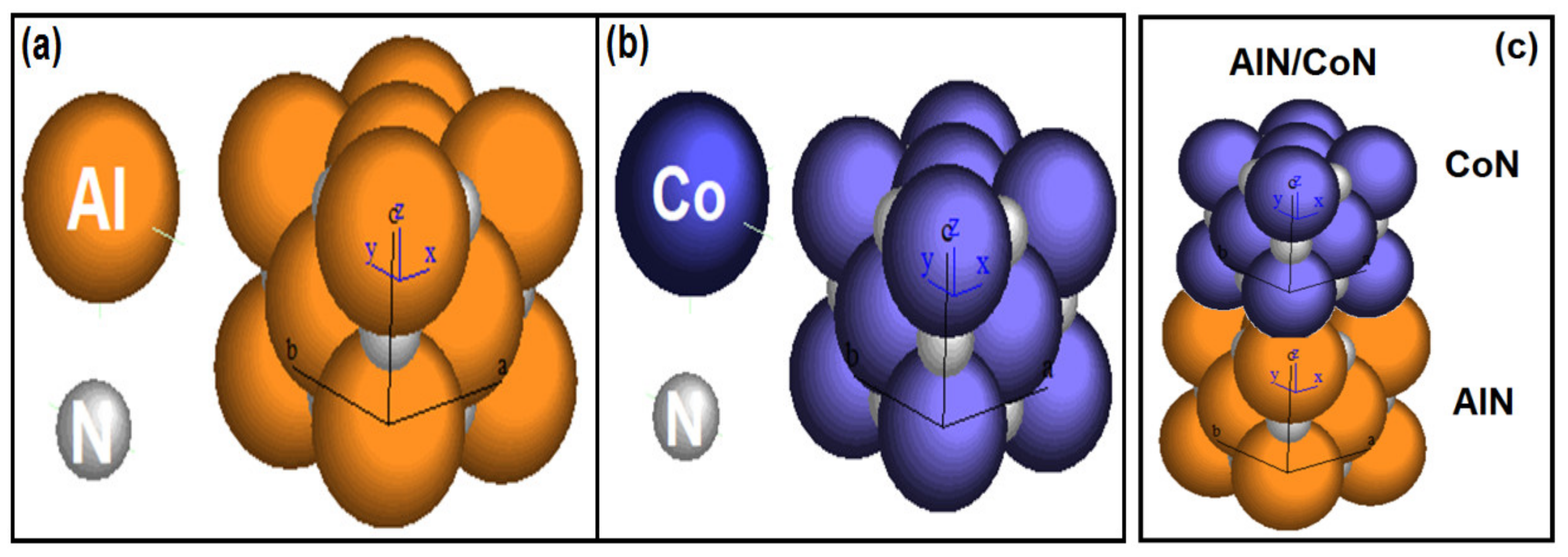
3.4. Crystallographic Simulation

Using the CaRIne Crystallography 3.1 software (CaRIne Crystallography, S.B. California, CA, USA), the crystal structure simulation for AlN and CoN single layers was carried out. The crystalline simulation used the network parameter obtained through the XRD analysis, the information regarding the spatial group of each material, data obtained from the JCPDF files and the occupation factor of the elements that constitute the layers obtained from the XPS results and vibration molecules analyzed by FTIR results. Thus, Table 3 shows the parameters necessary to carry out the simulation for AlN and CoN layers, therefore, (Figure 7a,b), present the unit cell structure for AlN and CoN layers, respectively. In both cases, a face-centered cubic crystalline structure (fcc) is shown in which the nitrogen atoms occupy the octahedral positions (½½½) while the positions (000) are occupied by the Al and Co atoms of each layer. Moreover, it was possible to observe the structural simulation for the [AlN/CoN]n multilayers (Figure 7c).
From the crystalline structure simulation for the two materials, an XRD pattern could be obtained in order to compare it with the one obtained experimentally, which exhibited a high level of approximation (Figure 8). Therefore, the Figure 8a,b shows the experimental and simulated diffraction pattern for the AlN molecule respectively. Also the Figure 8c,d show the experimental and simulated diffraction patterns for the CoN molecule, respectively, where it is observed that indeed the diffraction pattern obtained experimentally and the pattern obtained from the simulation share the diffraction angles and the intensities in the crystallographic directions of the Bragg planes within the range of 0 to 90° in which the X-ray diffraction test was carried out. Finally, from results of the computational simulation it is possible to analyze the lattice mismatch. Its value of 4.8% was determined, which introduced a compressive stresses and, together with the increase of the progressive interfaces, affected the electrochemical properties, generating a reduction in the corrosion rate.

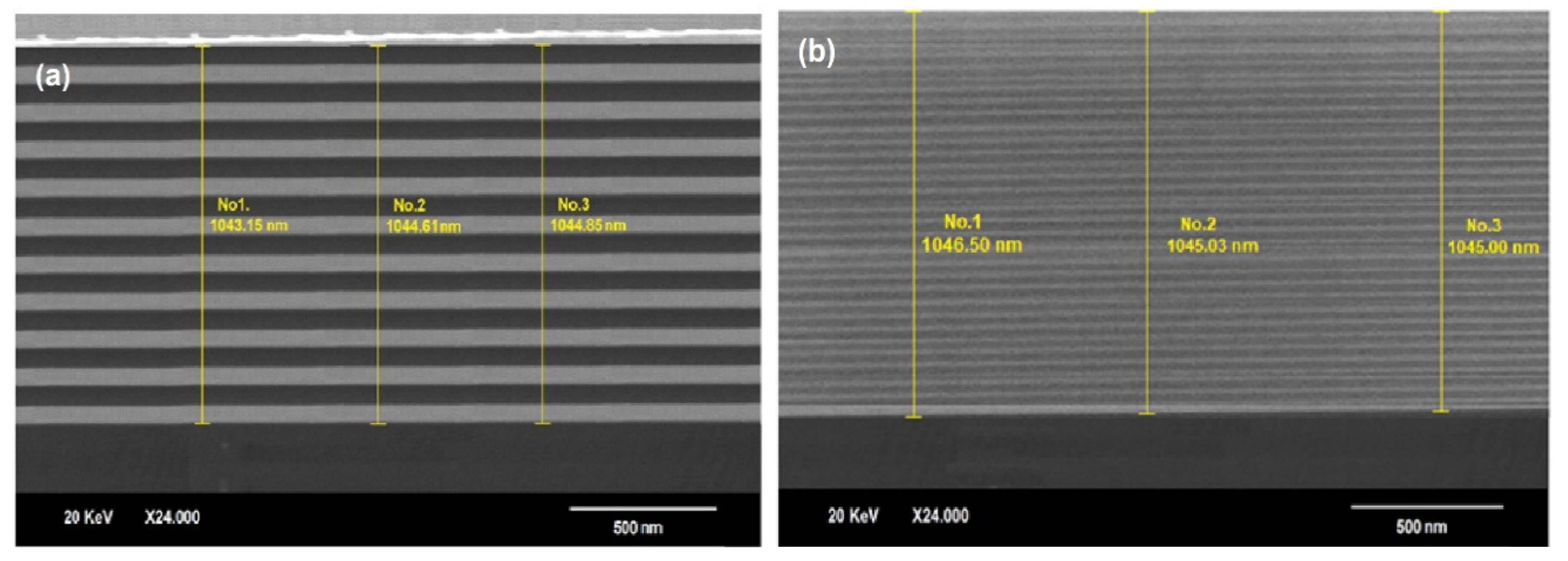
3.5. Scanning Electron Microscopy (SEM)

To determine the surface morphology of the [AlN/CoN]n multilayer coatings, scanning electron microscopy was performed. Figure 9 shows the SEM micrographs which were obtained from the cross section of the multilayers. The SEM micrographs in cross section were performed in the backscattered electron mode, showing a dense and continuous morphology, with absence of cracks and deformations. From the SEM micrographs, the approximate thickness of the coatings was determined to be 1.043 μm. Thicker layers associated with the coating deposited with n = 10 and with a spatial periodicity Λ = 104.3 nm can be observed in Figure 9a. On the other hand, less thick layers associated with the coating deposited with n = 30 and with a spatial periodicity Λ = 34.7 nm can be observed in Figure 9b.

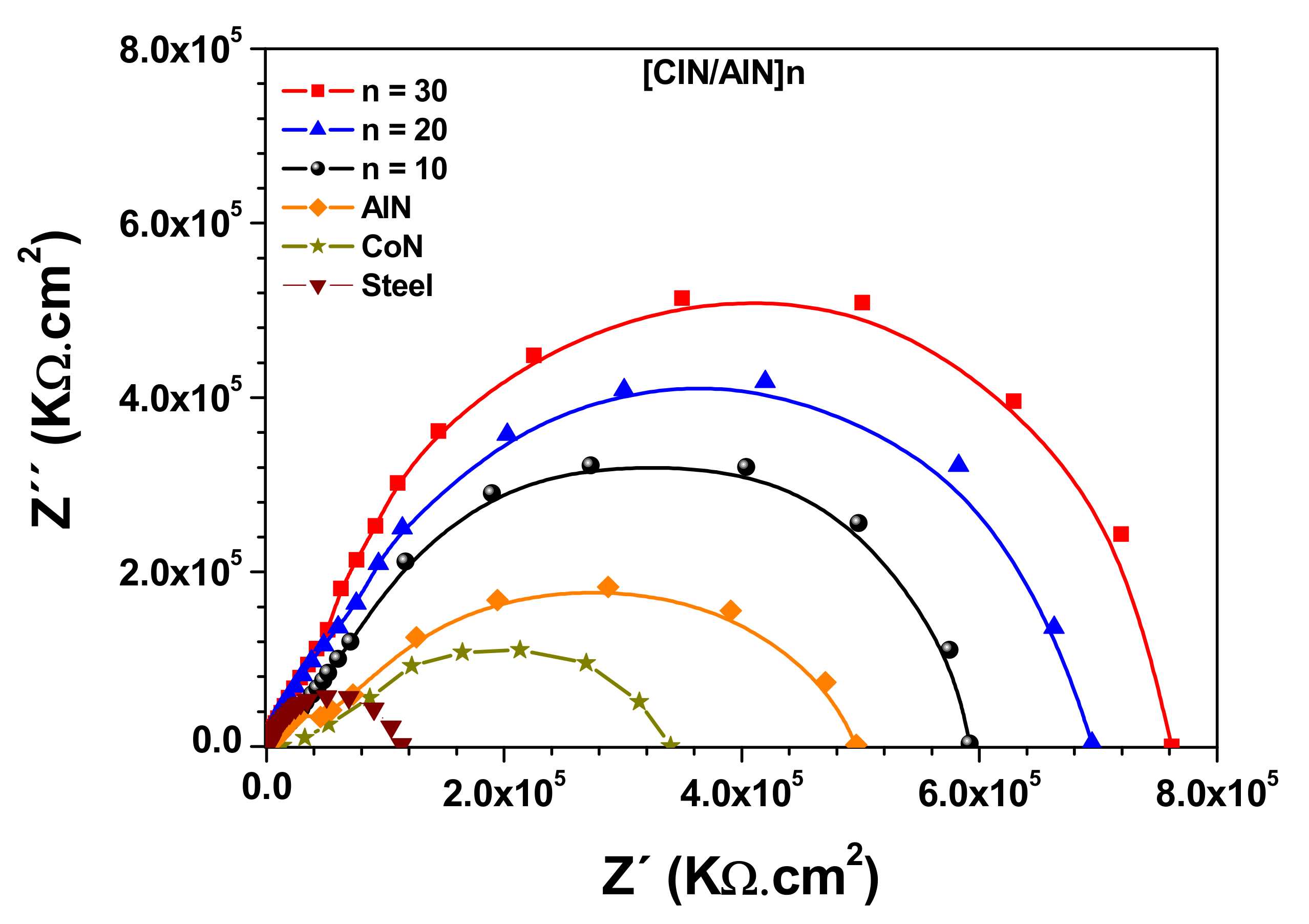
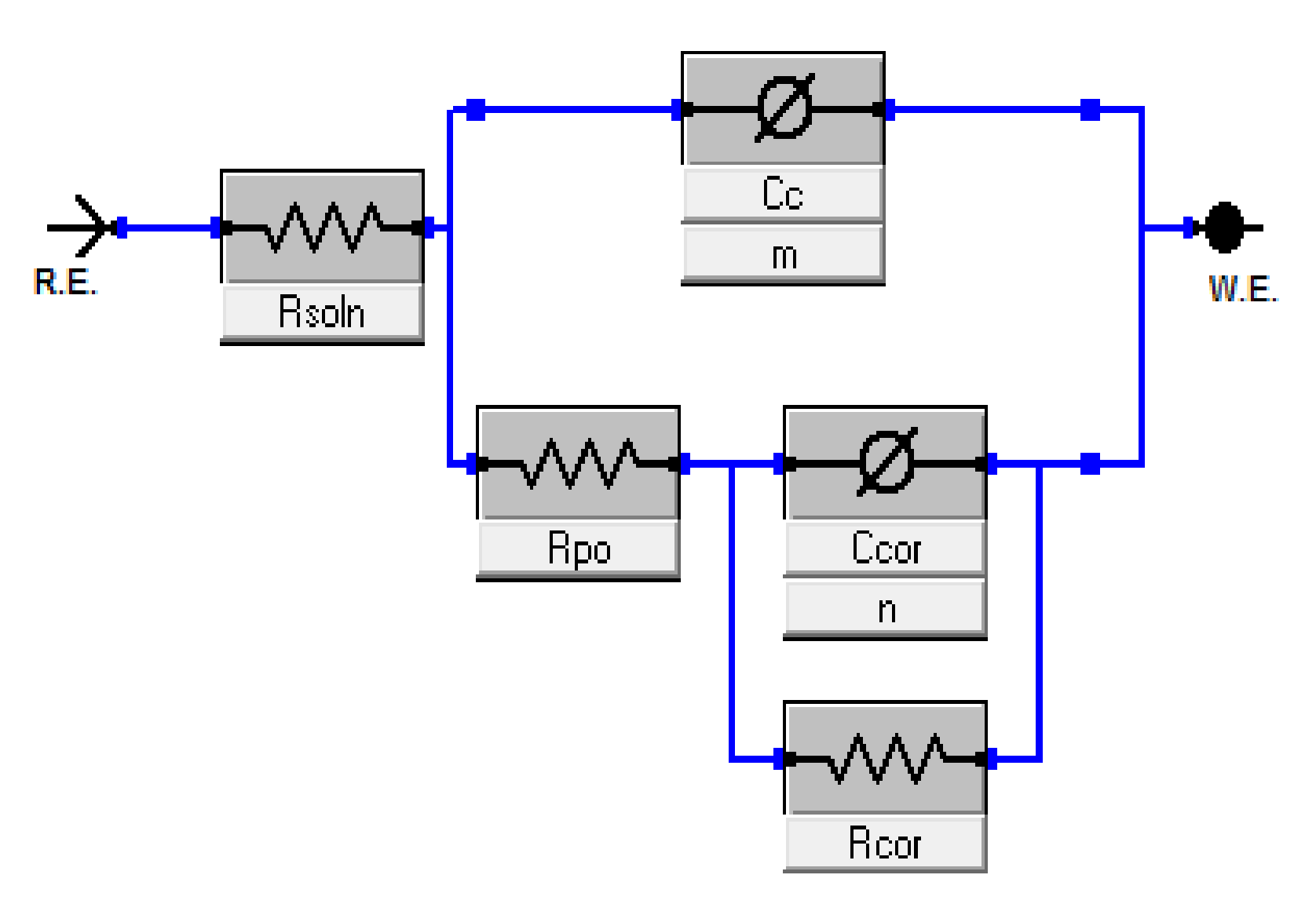
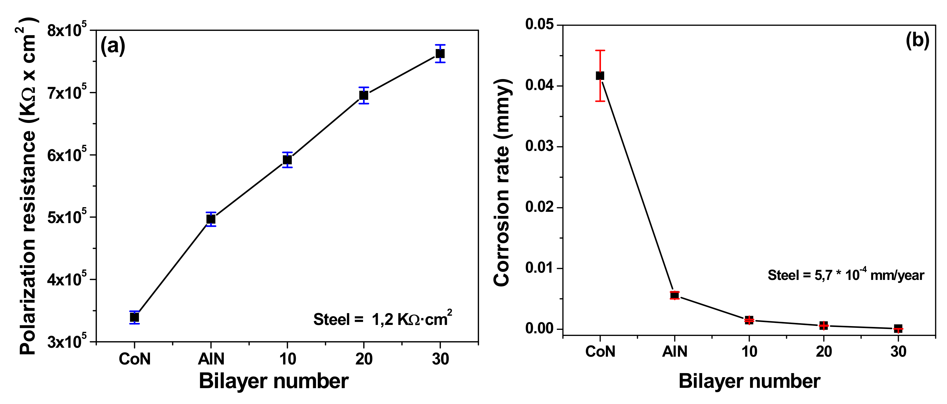
3.6. Electrochemical Characterization

The Nyquist plot are widely used in the materials characterization due to practical reasons. Therefore, it is more necessary in electrochemistry science taking in account that the Nyquist plot is very sensitive to surfaces changes, also for most common equivalent circuits some parameters can be read directly from the plot. Moreover, the Nyquist plot shows a characteristic shape depending on which components contribute to the impedance. The Nyquist plot shows very clearly even small changes in the studied surface. Thus, an interesting field of application is the study of corrosion, as EIS is particularly important for the study of single and multilayers coatings. Then analyzing the last discussion, a perfect coating will deliver a vertical line in a Nyquist plot, while a coating penetrated by aggressive electrolyte shows a semi-circle and corrosion under the coating has another shape. This way the status of coated metal can be evaluated and the electrolyte uptake of the coating can be determined [30,31]. Taking to account the last, Figure 10 displays the Nyquist diagram, imaginary part of the impedance versus its real part, for the [AlN/CoN]n multilayered grown at different bilayer period (Λ) and bilayer number (n). Figure 10 also shows the Nyquist diagram corresponding for AISI 302 steel coated with AlN and CoN single layers, in addition to the different [AlN/CoN]n multilayer systems. Also, the intercept of curve in the real part of the Nyquist diagram, can be used, for fit the experimental data. Due to that the system provides a Randles cell equivalent circuit which simulate the substrate-coating and coating-electrolyte interfaces (Figure 11), as a double layer capacitance in parallel with the coating resistance and the electrolyte resistance due to the reaction ion transfer from the electrolyte to the metallic substrate.
In Figure 11 the circuit used during this test is shown, this model is known as Randles cell, which indicates that the capacitance is in parallel with the impedance, due to the ion transfer reaction [32,33]. In this equivalent circuit the reference electrode (RE), the electrolyte resistance (RSoln), the pore resistance (Rpo), the coating polarization resistance (Rcor), the layer capacitance (Ccor) and the work electrode (WE) were observed.
Moreover, the Tafel curves of AISI 302 steel coated with AlN and CoN single layer, and the [AlN/CoN]n multilayer systems are presented in Figure 12. These curves allow to find the values of the anodic and cathodic slopes from the cathodic region (βc) and anodic region (βa), which are necessary to calculate the correct value of the corrosion rate for each coating, according with the insert in the Figure 12. Taking into account the results showed in the Figure 12, it can be observed that the corrosion potentials are more electropositive when the bilayer number increases and are greater than those presented by single layer-type coatings (Table 4). This fact possible confirms the protective effect generated by type [AlN/CoN]n coatings [34]. This behavior is characteristic of multilayer systems, which, as a consequence of the increase in the bilayers number (n) for the same total coating thickness, as well as the density and the number of interfaces, leads to an increase in the energy required for Cl ions to cross the substrate coating interfaces more freely, therefore, there is a reduction in solution ions that go to the substrate to produce corrosive damage.
From the Nyquist diagrams (Figure 10) it is observed that the polarization resistance values in multilayer systems based on aluminum nitride and cobalt nitride increase as the bilayers number (n) increases. So the corrosion mechanism indicates that the time for the (Cl) ions to cross through the entire coating to reach the metallic steel substrate is longer when the bilayers number increases (decrease in the bilayer period Λ). The analysis of this phenomenon complements the results obtained from the Tafel polarization curves (Figure 12) reaching a value of 7.62 × 10⁵ KΩ × cm2 for the [AlN/CoN]30 system (Figure 10). Therefore, Figure 13a describes the effect of the bilayers number on the corrosion rate of the coatings, where there is an inverse trend compared to the polarization resistance values obtained from the Nyquist diagrams (Figure 13b), said trend corroborates the protective effect of coatings as the bilayers number increases, reaching a value of 7.25 × 10⁻⁵ mmy for the [AlN/CoN]30 system.
Moreover, the lateral crystallite size reduction when the bilayers number increases, as observed in Table 1 from XRD results (Figure 2), is related to the crystal growth restriction as the individual thickness of each layer decreases, generating an increase in the interfaces number. Therefore, the reduction of the crystallite size affects the crystal lattice introducing compressive stresses, which restrict the mean free path of the Cl ions, positively affecting the corrosion resistance and reducing the corrosion rate.
From the polarization resistance values presented in Figure 13a, it is possible to calculate the coating porosity percentage (porosity factor (%P)), which corresponds to the relationship between the resistance to polarization of the substrate without coating and with coated substrate (Equation (2)) [35,36].
P =   R p s R p r
where P is the Porosity Factor, Rps is the resistance to polarization of the uncoated substrate and Rpr is the polarization resistance for substrate-coating system. Furthermore, based on the data in Table 4, the protection efficiency of the coatings was calculated by increasing the bilayers number (Figure 14b), therefore, this calculation was carried out using Equation (3) [35]:
E f % = I c o r r i I c o r r f I c o r r i 100
where Ef is the coating efficiency (coatings protection), Icorri is the value of the corrosion current for the uncoated substrate and Icorrf corresponds to the corrosion current of each coating. In this sense, Figure 14a presents the porosity factor of all coatings, where it is possible to find an inversely proportional relationship between this factor and the coating efficiency (Figure 14b). In this sense the coatings porosity is reduced and an increase in their coating efficiency is evidenced, this due to of coating densification effect when the number of layers were increased. This effect can be corroborated from X-ray diffraction analysis, where a deformation of the crystal lattice associated with compressive stress is observed when the bilayers number increases, which is associated with the structure densification and reduction of porosity in coatings. Moreover the Figure 14b shows the coatings efficiency as a function of the bilayers number increasing, where a higher percentage of efficiency is evidenced for multilayer systems in relation to the single layer coatings. In this sense, the best coating efficiency was observed for the [AlN/CoN]30 multilayer system, deposited with n = 30 bilayers, this can be attributed to the densification of the structure and the increase of interfaces due to the reduction of the spatial periodicity of the coatings. The high interfase number prevents the transport of the (Cl) ions that produce the corrosive damage and imply a greater protective effect of the coatings.

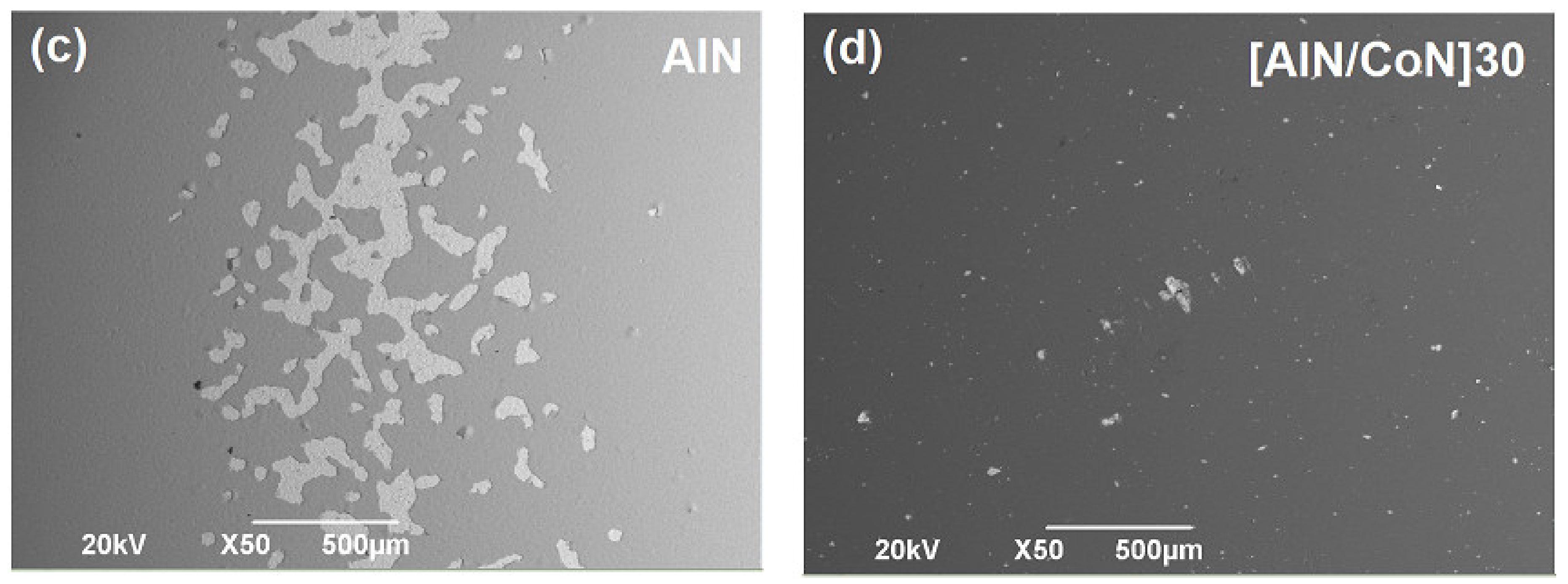
3.7. Surface Corrosion Analysis by SEM

In Figure 15 the scanning electron microscopy micrographs obtained after the corrosive process for uncoated steel surface (substrates) and steel substrates coated with the AlN and CoN single layers and the [AlN/CoN]n multilayers are shown, evidencing the protective effect of the coatings on the metallic surface substrate. In that sense, the best electrochemical response was obtained with the multilayer system deposited with n = 30. Therefore, in these micrographs, a high corrosive affectation degree can be seen on the surface for uncoated steel substrate (Figure 15a). Significant decrease in the surface corrosion products by the [AlN/CoN]30 multilayer system can be observed (Figure 15d) compared to the AlN (Figure 15b) and CoN (Figure 15c) single layer coatings.

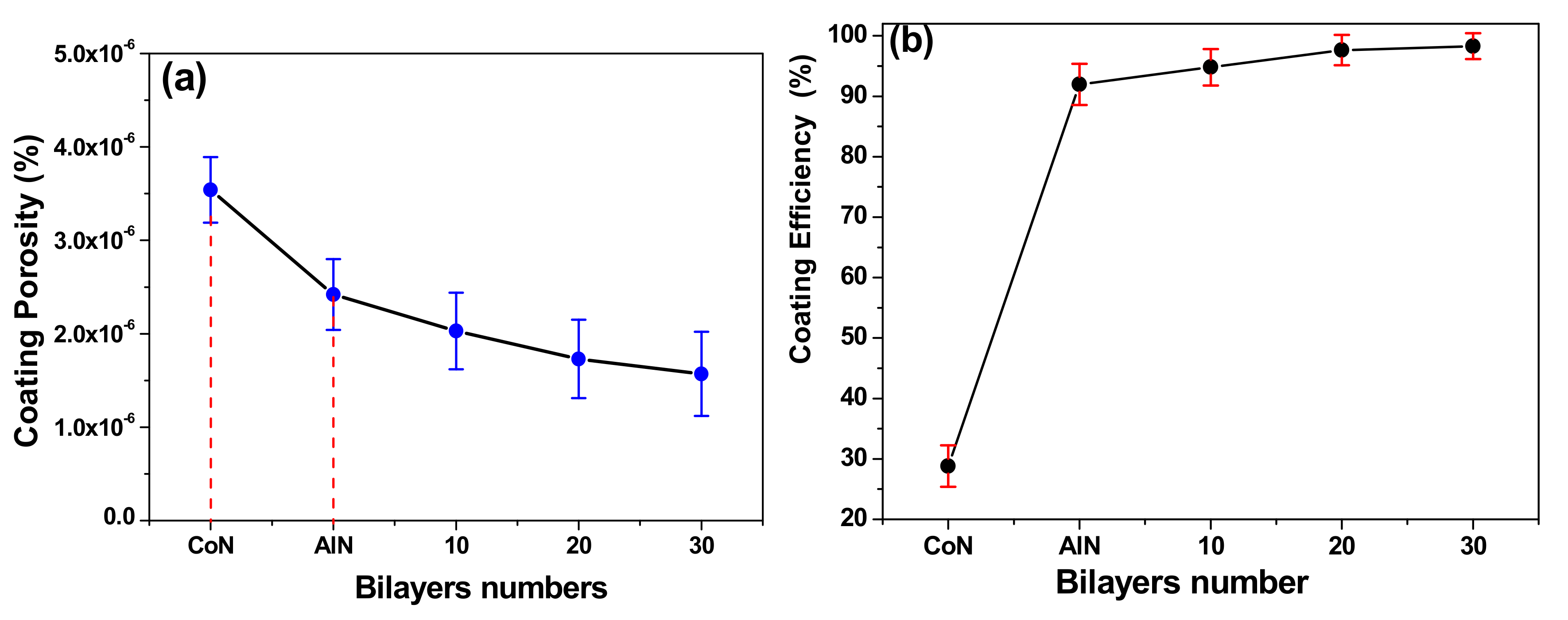
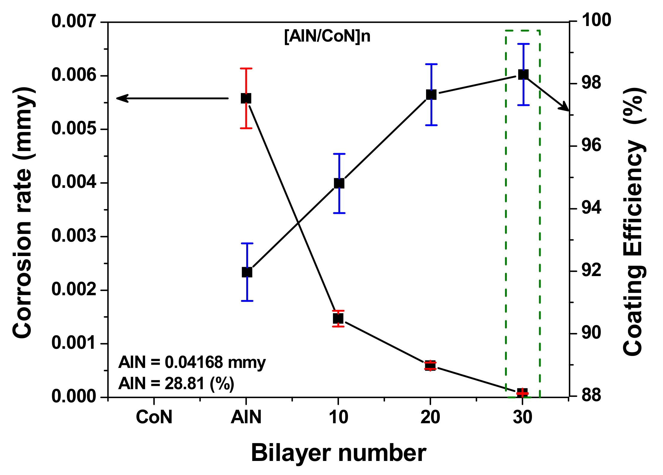
3.8. Correlation between Corrosion Rate and Coating Efficiency

Figure 16 shows the relationship between bilayer number (n), corrosion rate and coating efficiency for all [AlN/CoN]n multilayer coatings deposited on the industrial steel substrates. It is clearly shown that the reduction in the corrosion rate (Figure 13b), the increasing of the coating efficiency (Figure 14b) and the increase of interface number (Figure 9) when the spatial periodicity was reduced and the bilayer number (n) was increased. Therefore, the electrochemicals properties is associated with a increasing of the polarization resistance, due to the reduction in the coating porosity (Figure 14a). From this correlation it is possible to determine that one merit index [36,37] associated with the lowest corrosion rate and best coating efficiency at the same bilayer number (n) or spatial periodicity (Λ). Therefore, the [AlN/CoN]n multilayer coating deposited with n = 30 (Λ = 34.7 nm) offers the best synergy for electrochemical properties and efficiency properties with low corrosion and good coating efficiency which is very important for electrochemical applications in the metal-mechanic industry.

4. Conclusions

Protective coatings of AlN and CoN single layers and [AlN/CoN]n multilayers with crystallinity and stoichiometry consistent with transition metal nitrides, and with uniform modulations between AlN and CoN materials were obtained, thus, the crystallographic simulation from the XRD and XPS results revealed the formation of crystalline structures (FCC). From the electrochemical analysis (EIS and Tafel), an increase in the polarization resistance and reduction in the corrosion rate were observed when the bilayers number increased, which was reflected in a porosity reduction of 55.65% and an increase in coating efficiency of 70.96% for the [CoN/AlN]30 system with respect to the single layers system that presented the lowest values. This behavior is attributed to the increase in density and the number of interfaces when the bilayers number increases, which implies a greater resistance to the transit of Cl ions from the electrolyte to the steel substrate, thus generating protective effect.

Author Contributions

Conceptualization, J.C. and N.B.; methodology, J.C.; software, N.B.; validation, J.C., N.B. and W.A.; formal analysis, N.B.; investigation, J.C.; resources, W.A.; data curation, N.B.; writing—original draft preparation, J.C.; writing—review and editing, J.C.; visualization, J.C.; supervision, W.A.; project administration, W.A.; funding acquisition, W.A. All authors have read and agreed to the published version of the manuscript.

Funding

This research was supported by Universidad Militar Nueva Granada, Bogotá, Colombia.

Institutional Review Board Statement

Not applicable.

Informed Consent Statement

Not applicable.

Data Availability Statement

Not applicable.

Acknowledgments

This research was supported by Universidad Militar Nueva Granada, Bogotá, Colombia; CIC biomaGUNE, San Sebastian, Spain; Centro de Desarrollo Tecnológico y Asistencia Técnica a la Industria del Servicio Nacional de Aprendizaje (CDT-ASTIN-SENA), Cali, Colombia; Universidad Autónoma de Occidente, Cali, Colombia.

Conflicts of Interest

The authors declare no conflict of interest.

References

  1. Hariharan, R.; Raja, R.; Nimal, R.J.G.R. Characteristic of High performance on Mild Steel/AlN Cermet Selective Surfaces Deposited by rf Magnetron Sputtering. J. Crit. Rev. 2020, 4, 319–323. [Google Scholar]
  2. Florence, V.; Massiani, Y. Gergaud and O. Thomas. Stress, porosity measurements and corrosion behaviour of AlN films deposited on steel substrates. Thin Solid Film. 2000, 359, 221–227. [Google Scholar]
  3. De la Cruz, W.; Contreras, O.; Pérez-Tijerina, E.; Soto, G. Cobalt nitride films produced by reactive pulsed laser deposition. Rev. Mex. Fis. 2006, 52, 409–412. [Google Scholar]
  4. Wu, Z.G.; Zhang, G.A.; Wang, M.X.; Fan, X.Y.; Yan, P.X.; Xu, T. Structure and mechanical properties of Al/AlN multilayer with different AlN layer thickness. Appl. Surf. Sci. 2006, 253, 2733–2738. [Google Scholar] [CrossRef]
  5. Piedrahita, W.F.; Coy, L.E.; Amaya, C.; Llarena, I.; Caicedo, J.C.; Yate, L. Influence of the negative R.F. bias voltage on the structural, mechanical and electrical properties of Hf–C–N coatings. Surf. Coat. Technol. 2016, 286, 251–255. [Google Scholar] [CrossRef]
  6. Zandalazini, C.I.; Oliva, M.I.; Ferrero, J.C. Pulsed Laser Deposition: Development and implementation of the technique of grown of multilayers. An. AFA 2016, 27, 40–46. [Google Scholar] [CrossRef]
  7. Van Straaten, G.; Deckers, R.; Vos, M.F.J.; Kessels, W.M.M.; Creatore, M. Plasma-Enhanced Atomic Layer Deposition of Cobalt and Cobalt Nitride: What Controls the Incorporation of Nitrogen? J. Phys. Chem. C 2020, 124, 22046–22054. [Google Scholar] [CrossRef]
  8. Kayani, Z.N.; Riaz, S.; Naseem, S.H. Structural and Magnetic Properties of The Thin Film of Cobalt Nitride. Surf. Rev. Lett. 2014, 21, 1450081. [Google Scholar] [CrossRef]
  9. Kolaklieva, L.; Chitanov, V.; Szekeres, A.; Antonova, K.; Terziyska, P.; Fogarassy, Z.; Petrik, P.; Mihailescu, I.N.; Duta, L. Pulsed Laser Deposition of Aluminum Nitride Films: Correlation between Mechanical, Optical, and Structural Properties. Coatings 2019, 9, 195. [Google Scholar] [CrossRef] [Green Version]
  10. Wang, H.; Wang, W.; Yang, W.; Zhou, S.; Lin, Z.; Li, G. Growth evolution of AlN films on silicon (111) substrates by pulsed laser deposition. J. Appl. Phys. 2015, 117, 185303. [Google Scholar] [CrossRef]
  11. Svedberg, L.M.; Arndt, K.C.; Cima, M.J. Corrosion of Aluminum Nitride (AlN) in Aqueous Cleaning Solutions. J. Am. Ceram. Soc. 2000, 83, 41–46. [Google Scholar] [CrossRef]
  12. Taborda, J.A.P.; Caicedo, J.C.; Grisales, M.; Saldarriaga, W.; Riascos, H. Deposition pressure effect on chemical, morphological and optical properties of binary Al-nitrides. Opt. Laser Technol. 2015, 69, 92–103. [Google Scholar] [CrossRef]
  13. Gupta, R.; Pandey, N.; Tayal, A.; Gupta, M. Phase formation, thermal stability and magnetic moment of cobalt nitride thin films. AIP Adv. 2015, 5, 097131. [Google Scholar] [CrossRef]
  14. Iqbal, A.; Mohd-Yasin, F. Reactive Sputtering of Aluminum Nitride (002) Thin Films for Piezoelectric Applications: A Review. Sensors 2018, 18, 1797. [Google Scholar] [CrossRef] [PubMed] [Green Version]
  15. Smecca, E.; Maita, F.; Pellegrino, G.; Vinciguerra, V. AlN texturing and piezoelectricity on flexible substrates for sensor applications. Appl. Phys. Lett. 2015, 106, 232903. [Google Scholar] [CrossRef]
  16. Helmersson, U.; Todorova, S.; Barnett, S.A.; Sundgren, J.-E.; Markert, L.C.; Greene, J.E. Growth of single-crystal TiN/VN strained-layer superlattices with extremely high mechanical hardness. Appl. Phys. 1987, 62, 481. [Google Scholar] [CrossRef]
  17. Rosenberger, L.; Baird, R.; McCullen, E.; Auner, G.; Shreve, G. XPS analysis of aluminum nitride films deposited by plasma source molecular beam epitaxy. Surf. Interface Anal. 2008, 40, 1254–1261. [Google Scholar] [CrossRef]
  18. Motamedi, P.; Cadien, K. XPS analysis of AlN thin films deposited by plasma enhanced atomic layer deposition. Appl. Surf. Sci. 2014, 315, 104–109. [Google Scholar] [CrossRef]
  19. Li1, H.; Cai, G.M.; Wang, W.J. Room temperature luminescence and ferromagnetism of AlN:Fe. AIP Adv. 2016, 6, 065025. [Google Scholar]
  20. Dallaev, R.; Sobola, D.; Tofel, P.; Škvarenina, L.; Sedlák, P. Aluminum Nitride Nanofilms by Atomic Layer Deposition Using Alternative Precursors Hydrazinium Chloride and Triisobutylaluminum. Coatings 2020, 10, 954. [Google Scholar] [CrossRef]
  21. Kim, S.I.; Lee, S.R.; Ho, J.; Ahn, B.T. Epitaxial Growth of CoSi 2 Layer on a Si 100 Substrate Using a CoN x Interlayer Deposited by Reactive Sputtering. Korean, J. Mater. Res. 2006, 16, 16–21. [Google Scholar] [CrossRef]
  22. Parnell, C.M.; Chhetri, B.; Mitchell, T.; Watanabe, F. Simultaneous Electrochemical Deposition of Cobalt Complex and Poly(pyrrole) Thin Films for Supercapacitor Electrodes. Sci. Rep. 2019, 9, 5650. [Google Scholar] [CrossRef] [PubMed]
  23. Zhang, Y.; Long, G.; Tan, H.; Wang, Z.; Zhang, Z.; Gao, W.; Rawat, R.S.; Fan, H.J. Enhancing bifunctionality of CoN nanowires by Mn doping for long-lasting Zn-air batteries. Sci. China-Chem. 2020, 63, 890–896. [Google Scholar] [CrossRef]
  24. Antsiferov, V.; Gilyov, V.; Karmanov, V. IR-Spectra and Phases Structure of Sialons. Vib. Spectrosc. 2002, 30, 169–173. [Google Scholar] [CrossRef]
  25. Andrews, L.; Zhou, M.; Chertihin, G.V.; Bare, W.D.; Hannachi, Y. Reactions of Laser-Ablated Aluminum Atoms with Nitrogen Atoms and Molecules. Infrared Spectra and Density Functional Calculations for the AlN. J. Phys. Chem. A 2000, 104, 1656–1661. [Google Scholar]
  26. Thompson, W.E.; Jacox, M.E. The vibrational spectra of molecular ions isolated in solid neon. III. N+4. J. Chem. Phys. 1990, 93, 3856–3862. [Google Scholar] [CrossRef]
  27. Dallaev, R.; Papež, N.; Sobola, D.; Ramazanov, S. Investigation of structure of AlN thin films using Fourier-transform infrared spectroscopy. Procedia Struct. Integr. 2019, 23, 601–606. [Google Scholar] [CrossRef]
  28. Andrews, L.; Citra, A.; Chertihin, G.V.; Bare, W.D.; Neurock, M. Reactions of Laser-Ablated Co and Ni Atoms with Nitrogen Atoms and Molecules. Infrared Spectra and DFT Calculations of Metal Nitride Molecular Species and Complexes. J. Phys. Chem. A 1998, 102, 2561–2571. [Google Scholar] [CrossRef]
  29. Thompson, W.E.; Jacox, M.E. The vibrational spectra of molecular ions isolated in solid neon. XI. NO+2, NO−2, and NO−3. J. Phys. Chem. 1993, 99, 7399. [Google Scholar] [CrossRef]
  30. Ituen, E.; James, A.; Akaranta, O. Fluvoxamine-based corrosion inhibitors for J55 steel in aggressive oil and gas well treatment fluids. Egypt. J. Pet. 2017, 26, 745–756. [Google Scholar] [CrossRef] [Green Version]
  31. Diard, J.; le Gorrec, B.; Montella, C. Handbook of Electrochemical Impedance Spectroscopy; Diffusion Impedances; Technical Report; Elsevier: Amsterdam, The Netherlands, 2020. [Google Scholar]
  32. Randles, J.E.B.; Schiffrin, D.J. Surface tension of dilute acid solutions. Trans. Faraday Soc. 1966, 62, 2403–2408. [Google Scholar] [CrossRef]
  33. Schäfer, H.; Stock, H.-R. Improving the corrosion protection of aluminium alloys using reactive magnetron sputtering. Corros. Sci. 2005, 47, 953–964. [Google Scholar] [CrossRef]
  34. Fenker, M.; Balzer, M.; Jehn, H.A.; Kappl, H.; Lee, J.J.; Lee, K.H.; Park, H.S. Improvement of the Corrosion Resistance of Hard Wear Resistant Coatings by Intermediate Plasma Etching or Multilayered Structure. Surf. Coat. Technol. 2002, 150, 101–106. [Google Scholar] [CrossRef]
  35. Caicedo, J.; Zambrano, G.; Aperador, W.; Escobar-Alarcon, L.; Camps, E. Mechanical and electrochemical characterization of vanadium nitride (VN) thin films. Appl. Surf. Sci. 2011, 258, 312–320. [Google Scholar] [CrossRef]
  36. Caicedo, J.C.; Yate, L.; Cabrera, G.; Aperador, W.; Zambrano, G.; Prieto, P. Effect of negative bias voltage on mechanical and electrochemical nature in Ti–W–N coatings. J. Mater. Sci. 2011, 46, 1244–1252. [Google Scholar] [CrossRef]
  37. Gu, Z.W.; Han, Y.; Pan, F.S.; Wang, X.; Weng, D.; Zhou, S. Investigation on Wear- and Corrosion Resistance of TiN Films by CVD. Mater. Sci. Forum 2009, 610, 554–558. [Google Scholar]
Figure 1. Image associate to PLD (pulsed laser deposition) device and the experimental processes used for the deposition of coatings by means of PLD.
Metals 11 02049 g001
Figure 2. Diffractograms of the AlN and CoN single layer and [AlN/CoN]n multilayer coatings with different number of bilayers (n = 10, 20, 30). The dotted lines indicate the position of the peaks obtained from international index files (JCPDF).
Metals 11 02049 g002
Figure 3. XPS depth spectra of the coatings: (a) AlN single layer and (b) CoN single layer.
Metals 11 02049 g003
Figure 4. High resolution XPS spectra for AlN and CoN layers: (a) N1s signal in the (AlN) layer, (b) N1s signal in the (CoN) layer, (c) Al2p signal in the (AlN) layer and (d) Co2p signal in the (CoN) layer.
Metals 11 02049 g004
Figure 5. Elemental percentages according to the coating stoichiometry (a) aluminum nitride layer (Al74N26), (b) cobalt nitride layer (Co69N31).
Metals 11 02049 g005
Figure 6. FTIR spectra obtained from the single layer coatings: (a) Aluminum nitride (AlN) and (b) Cobalt nitride (CoN).
Metals 11 02049 g006
Figure 7. Unit cell crystallographic simulation obtained using CaRIne Crystallography 3.1 software: (a) AlN materials, (b) CoN materials and (c) [AlN/CoN]n mulyilayers.
Metals 11 02049 g007
Figure 8. Diffraction patterns obtained for all coatings: (a) AlN diffraction pattern (experimental), (b) AlN diffraction pattern (simulated), (c) CoN diffraction pattern (experimental) and (d) CoN diffraction (simulated).
Metals 11 02049 g008aMetals 11 02049 g008b
Figure 9. SEM micrographs of the cross section of the [AlN/CoN]n multilayer coatings: (a) [AlN/CoN]10 Λ = 104.3 nm and (b) [AlN/CoN]30 (Λ = 34.7 nm).
Metals 11 02049 g009
Figure 10. Electrochemical impedance diagrams for AISI 302 steel coated with AlN and CoN single layers and multilayer systems [AlN/CoN]n.
Metals 11 02049 g010
Figure 11. Equivalent circuit used to fit the experimental data in the multilayer systems [AlN/CoN]n.
Metals 11 02049 g011
Figure 12. Tafel curves for AISI 302 steel coated with AlN and CoN single layers and [AlN/CoN]n multilayer systems.
Metals 11 02049 g012
Figure 13. Bilayers number effect on the [AlN/CoN]n multilayers system: (a) polarization resistance and (b) corrosion rate.
Metals 11 02049 g013
Figure 14. Electrochemical properties: (a) Porosity factor of coatings and (b) coating efficiency percentage.
Metals 11 02049 g014
Figure 15. SEM micrographs of the corrosive process for uncoated and coated steel substrates: (a) uncoated stainless steel, (b) cobalt nitride (single layer), (c) aluminum nitride (single layer) and (d) multilayer [AlN/CoN]30.
Metals 11 02049 g015aMetals 11 02049 g015b
Figure 16. Correlation between corrosion rate and coating efficiency for the [AlN/CoN]n multilayer coatings deposited as a function of the increasing bilayer number (n).
Metals 11 02049 g016
Table 1. Crystallographic lateral crystallite size for AlN, CoN [AlN/CoN]n materials.
CoatingsLateral Crystallite Size (nm)Bragg PlanePreferential Direction
cAlN53(200)-
CoN47(200)-
[AlN/CoN]1044-(200)
[AlN/CoN]2040-(200)
[AlN/CoN]3037-(200)
Table 2. Chemical composition and stoichiometric relation for all AlN and CoN coatings from XPS results.
Chemicals Elements (%)
CoatingsAlCoNN/AlN/Co
AlN74--260.35--
CoN--6931--0.45
Table 3. Crystallographic Simulation parameters for AlN and CoN materials.
Crystallographic Simulation Parameters
CoatingsCrystal StructureSpace GroupLattice Parameter (a0) (Å)Stoichiometric Ratio
AlNFCCFm3m3.55Al74N26
CoNFCCF43m3.73Co69N31
Table 4. Results calculated from Tafel polarization curves.
SystemsEcorr (mV)Icorr (nA)
Single layer CoN−68.7182.40
Single layer AlN−525.08.45
[AlN/CoN]10−360.06.98
[AlN/CoN]20−189.04.41
[AlN/CoN]30−92.01.99
Publisher’s Note: MDPI stays neutral with regard to jurisdictional claims in published maps and institutional affiliations.

