Article

Effect of Ni-Coated Carbon Nanotubes Additions on the Eutectic Sn-0.7Cu Lead-Free Composite Solder

1
China Nuclear Power Operation Technology Co., Ltd., Wuhan 430223, China
2
School of Materials and Physics, China University of Mining and Technology, Xuzhou 221116, China
*
Author to whom correspondence should be addressed.
Metals 2022, 12(7), 1196; https://doi.org/10.3390/met12071196
Submission received: 13 June 2022 / Revised: 11 July 2022 / Accepted: 12 July 2022 / Published: 14 July 2022
(This article belongs to the Special Issue New Welding Materials and Green Joint Technology)

Abstract

:
Sn-0.7Cu-based (all in wt.% unless specified otherwise) composite solders functionalized with Ni-coated carbon nanotubes (CNTs) with various weight proportions ranging from 0.01 to 0.2 wt.% were successfully produced. The Ni-coated CNTs were synthesized with discontinuous nickel coating by an improved electroless nickel plating technique. The microstructural, melting and wetting properties of Sn-0.7Cu-based composite solders were evaluated as a function of different amounts of Ni-coated CNTs addition. Compared to Sn-0.7Cu, it was observed that the microstructure of the composite solder added to the Ni-coated CNTs was still composed of the intermetallic compound Cu6Sn5 in a β-Sn matrix, but the micromorphology changed greatly. When 0.05 wt.% Ni-coated CNTs were added, the rod-shaped Cu6Sn5 particles disappeared, and all appeared in a form of dot-shaped Cu6Sn5 particles. DSC results showed only a slight decrease in the melting behavior of the composite solder. Experimental results unveiled that the addition of Ni-coated CNTs to Sn-0.7Cu solder could improve the wettability. With the addition of 0.05 wt.% Ni-coated CNTs, the wetting angle decreased by 13.35%, and an optimum wetting angle of 25.44° was achieved.

1. Introduction

The tin-lead eutectic alloy system has been widely used in soldering applications in advanced electronic components for decades because of its good mechanical, thermal and electrical properties [1]. However, legislation and regulations have been imposed to forbid the use of Pb due to the toxicity of lead, which poses a great challenge to traditional electronic assembly technology.
A great number of lead-free solder alloys have since emerged to replace the Tin-lead eutectic alloy [2], including Sn-Ag, Sn-Zn, Sn-Bi, Sn-Cu and Sn–Sb [3]. Among these alloys, the eutectic Sn-0.7Cu has been widely studied as a lead-free solder alloy. The Sn-0.7Cu solder alloy aroused wide attention due to its excellent mechanical properties and reasonable price [4,5,6]. However, the application of Sn-0.7Cu system lead-free solder alloy was limited by the precipitation phase intermetallic compound (IMC) Cu6Sn5 and its poor wettability [7]. Some nanoscale particles, such as TiO2 [8,9], SnO2 [10], SiC [11] and CNTs [12,13] were thus added to the Sn-Cu alloy to improve its microstructure and wettability. Since their discovery in 1991 by Iijima [14], CNTs have attracted extensive attention due to their excellent mechanical and electrical properties [15,16]. However, two factors still limited the best use of the outstanding properties of CNTs, that is, higher surface energy results in poor bonding with metals and difficulty to homogeneously disperse the CNTs in the metal-based matrix because of its high length-diameter ratio [17]. T.P. Kumar et al. [18,19,20] reported a weak interaction between Sn and CNTs. In order to improve the bonding force between the solder alloy and the carbon nanotubes, a suitable layer of metal was plated on the surface of carbon nanotubes by electroless plating. Previous research reported that such alloys as Ag [21], Ni [22,23,24], Ni-P [25] and Au [26] were deposited on the surface of CNTs to improve their affinity. Zhao et al. [27] proved that Ag-coated multi-walled carbon nanotubes (MWCNTs) were wetted to a certain degree by melted Sn, and embedded well in the matrix. Han et al. [28] reported that the addition of Ni-coated CNTs into Sn-Ag-Cu solder improved the wettability, where the Ni-coated CNT was the one with continuous nickel coating. This might not take full advantage of CNTs. Changing the distribution and morphology of nickel particles on the CNTs by improved electroless nickel plating could make the best of the CNTs and optimize of performance of the composite solder.
In this paper, Sn-0.7Cu-based composite solders functionalized with Ni-coated carbon nanotubes with various weight proportions ranging from 0.01 to 0.2 wt.% were successfully produced. The composite solder’s microstructural morphology, melting temperature and wettability with the addition of different contents of Ni-coated nanotubes were researched. It is found that the precipitation phase IMC Cu6Sn5 is refined, and the wettability of the solder is improved.

2. Materials and Methods

2.1. Synthesis of Ni-Coated Nanotubes

Multi-walled carbon nanotubes were Ni-coated by an improved electroless plating method [22]. First, the CNTs were purified and oxidized by concentrated HNO3 at 80 °C for 30 min. Then, after standing for 24 h, the CNTs were rinsed with deionized water to the neutral one and put into a freeze dryer to dry completely. The purified CNTs were put into an aqueous solution (until the supernatant appeared) of 20 mL/L HCl and 30 g/L SnCl2·H2O, stirred for 10 min, and treated ultrasonically for 10 min, then centrifuged with deionized water several times to a neutral state. Next, the sensitized CNTs were immersed in an aqueous mixture of 10 mL/L HCl and 0.2 g/L PdCl2, stirred and treated ultrasonically for 10 min, respectively, then centrifuged with deionized water several times to a neutral state. Lastly, the activated CNTs were put into a small amount of dilute HCHO solution to disperse evenly. Then, the solution was added to the planting bath at 70 °C. The plating solution was made by mixing the solutions of NiSO4·6H2O 24 g/L, Na3C6H5O7 145 g/L, (NH)4SO4·H2O 20 g/L, NaH2PO2·H2O 20 g/L, and the solution was adjusted by NH3·H2O to PH 10.5. After a 20 min deposition process, the Ni-coated CNTs were centrifuged with deionized water several times to a neutral state. The Ni-P alloy coating obtained by reductant NaH2PO2 was nano-structured without heat treatment [29]. So, the Ni-coated CNTs were heated. The heat treatment temperature was 700 °C for 2 h under the nitrogen atmosphere.

2.2. Preparation of Nanotube Loaded Composite Solder

Tin (Sn) and copper (Cu) with a purity > 99.5%, were obtained from Shanghai Macklin Biochemical Company. First, the fixed quantity of tin and copper powder was weighed and then Ni-coated carbon nanotubes with different proportions were added. In order to disperse them evenly, ball milling was used with the addition of ethanol. The ball milling speed was set at 250 r/min, and every 5 min reverse rotation was counted as a cycle, with a total of 12 cycles of continuous ball milling. After being mixed evenly, the mixture was dried in the vacuum state and pressed into cylindrical blocks, then these blocks were put into the tube furnace under argon protection for 550 °C melting for 1 h.

2.3. Melting Point Test

Melting temperatures of the composite solders were investigated by differential scanning calorimetry (DSC 404-F3). The DSC samples were obtained by cutting the prepared solders at a weight of 5–15 mg. The samples were placed in corundum crucibles which were heated from 30 °C to 300 °C and cooled from 300 °C to 50 °C at a rate of 5 °C/min, under an Ar atmosphere.

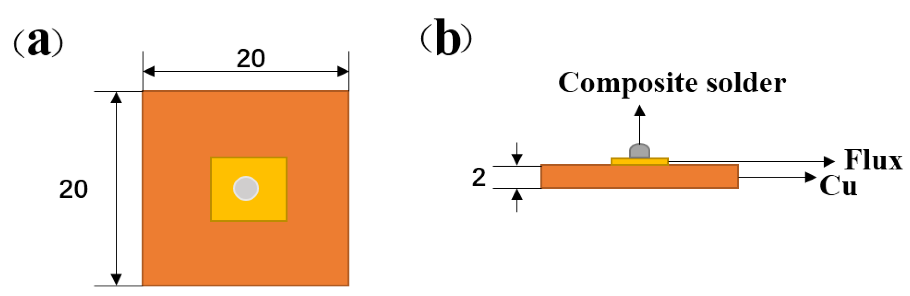
2.4. Solder Wettability Test

Solder wettability was characterized by the wetting angle of the solder. The Cu substrate with a purity of 99.99% and a dimension of 20 mm × 20 mm × 2 mm was polished and ultrasonically rinsed in dilute HCl solution and alcohol in sequence and then air-dried at room temperature. First, 0.2 g composite solder samples were put into boiling glycerol to form ball particles, then cleaned with alcohol after cooling down. The specimens coated with rosin mildly activated (RMA) flux were placed one by one on the substrate that was also coated with the RMA flux (Figure 1). Wettability tests were conducted in argon flow at 280 °C, with a dwell time of 5 min in a tube furnace, and the specimens were cooled down in the air. The wetting angle of the solder on the substrate was calculated by the wetting angle tester (JGW-360A, Chenghui, Chengde, China).

2.5. Microstructural Characterization

The X-ray diffraction (XRD) patterns of the samples were recorded using an X-ray diffractometer (XRD, D8-Advance, Bruker, Germany). Transmission electron microscopy (TEM) images of the sample were obtained using a JEM-1200EX microscope (TEM, JEOL, Tokyo, Japan). Morphologies of the Ni-coated nanotubes were investigated by field-emission scanning electron microscopy (FE-SEM, S-4800, Hitachi Limited, Tokyo, Japan).

3. Results and Discussion

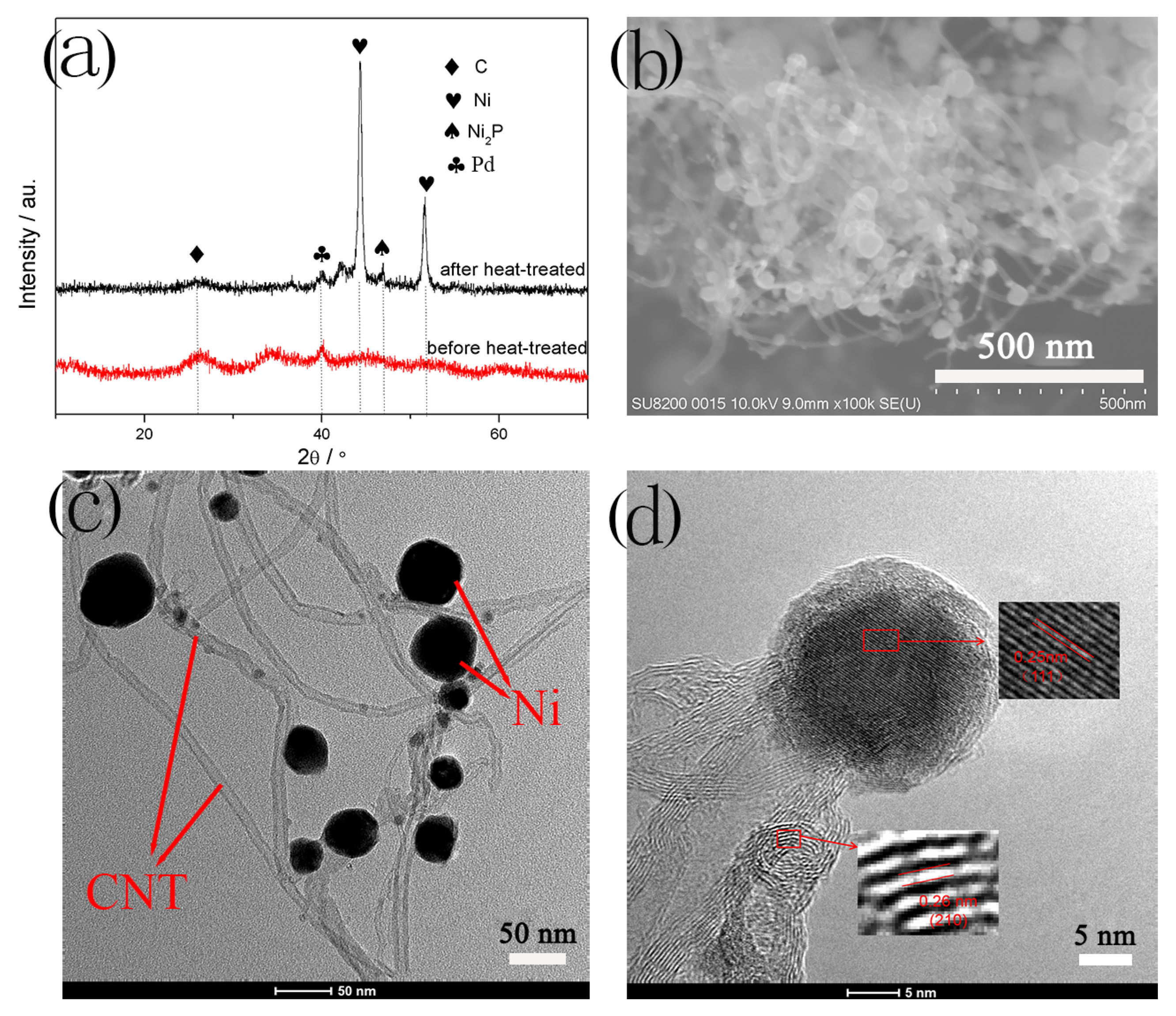
3.1. Ni-Coated Multi-Walled Carbon Nanotubes

The phase structure of the Ni-coated CNTs was analyzed by XRD (Figure 2a). Before heat treatment, the XRD pattern consisted of some broad amorphous peaks and no crystalline phase was discernible. Strong diffraction peaks appeared after heat treatment. A small diffraction peak at 2θ = 26.4° was the diffraction peak of the CNTs. The intensity peaks at 2θ = 44.5° and 51.8° were the corresponding peaks of (111) and (200) planes of nickel. A small Ni2P diffraction peak appeared at about 2θ = 47°, corresponding to the (210) plane. It is important to note that at 2θ = 40°, a diffraction peak appeared and was calibrated as the peak of Pd. The reason is that the nickel was not plated after planting. Therefore, both Ni and Ni2P were coated on the CNTs after the electroless nickel plating. The morphology of the Ni-coated CNTs after heat treatment was characterized by SEM (Figure 2b). It can be seen that after heat treatment, many Ni particles and Ni2P grew on the surface of the CNTs. In the place with dense CNTs, a small amount of agglomeration occurred, and the nickel particles were evenly coated in the edge area, with high crystallinity, which coincides with the XRD pattern. Figure 2c shows the TEM image of Ni-coated CNTs. Obviously, two different sizes of particles grew on CNTs, with a larger particle diameter of about 45 nm, and a smaller one of about 10 nm. It is known that the larger ones were Ni particles, and the smaller ones were Ni2P particles after the analysis in Figure 2d. These particles grew on the activation point of CNTs, and there was no particle shedding, indicating the strong adhesion between CNTs and particles. The high-resolution TEM (HRTEM) image (Figure 2d) shows that these particles with clear lattice fringes were attached. The lattice fringes of larger particles were about 0.25 nm in size, corresponding to the plane (111) of Ni. The lattice fringes of smaller particles were about 0.26 nm in size, corresponding to the plane (210) of Ni2P. This result further confirmed that electroless nickel plating was actually Ni-P plating.

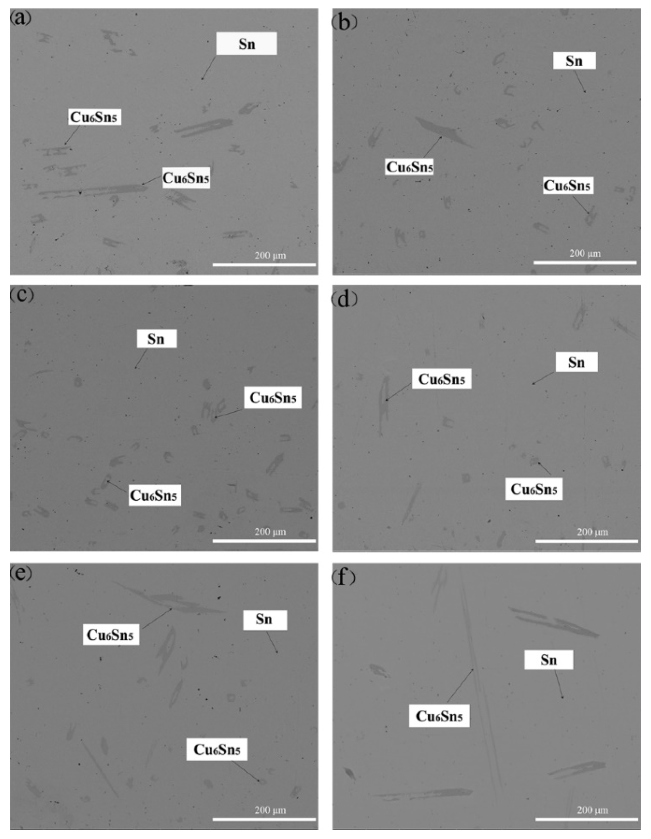
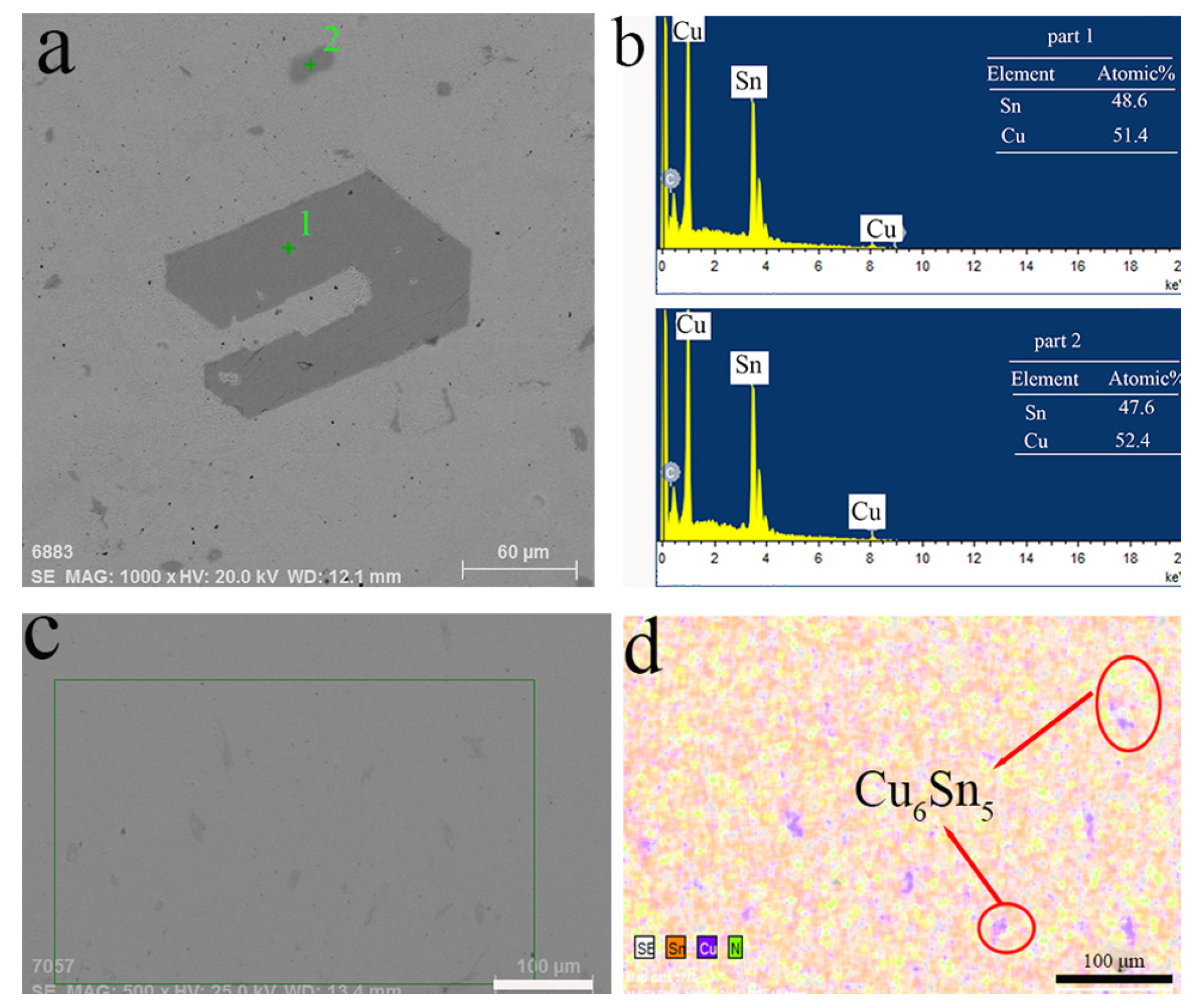
3.2. Solder Microstructure Analysis

Detailed features of the composite solder were seen by SEM micrographs. The SEM micrograph of the solder specimen without reinforcement was shown in Figure 3a. The SEM micrographs of the composite solder were shown in Figure 3b–f.
Figure 3 represented the FE-SEM micrographs of the composite solders. Obviously, one kind of grains was observed in the microstructure. The dark gray rounded grains were Cu6Sn5 and dispersed evenly in the β-Sn matrix. Rod-shaped Cu6Sn5 particles and some dot-shaped Cu6Sn5 particles dispersed in the Sn-0.7Cu solder without any reinforcement. When 0.05 wt.% Ni-coated CNTs added, the rod-shaped Cu6Sn5 particles disappeared, and all appeared in a form of dot-shaped Cu6Sn5 particles. The average size in the secondary phases was about 20 μm in the 0.05 wt.% Ni-coated CNTs reinforced solders as seen in Figure 3c. The microstructure of the composite solder was distinctly refined. However, the number of dot-shaped Cu6Sn5 particles decreased while the number of coarsened rod-shaped Cu6Sn5 particles increased with a Ni-coated CNTs concentration from 0.1 wt.% to 0.2 wt.%, as shown in Figure 3d–f.
Figure 4 shows energy-dispersive X-ray spectroscopy (EDS) analysis of composite solder after the addition of Ni-coated CNTs. Two kinds of dark particles were analyzed (Figure 4a,b). From the EDS results, it was seen that the particles consist of Cu and Sn atoms. According to the elemental analysis, the particles were identified as Cu6Sn5. It could be seen from the red circles (Figure 4d) that there were many green nickel elements at the corner of the intermetallic compound Cu6Sn5. This indicated that Ni-coated CNTs inhibited the growth of Cu6Sn5 in the composite solder.

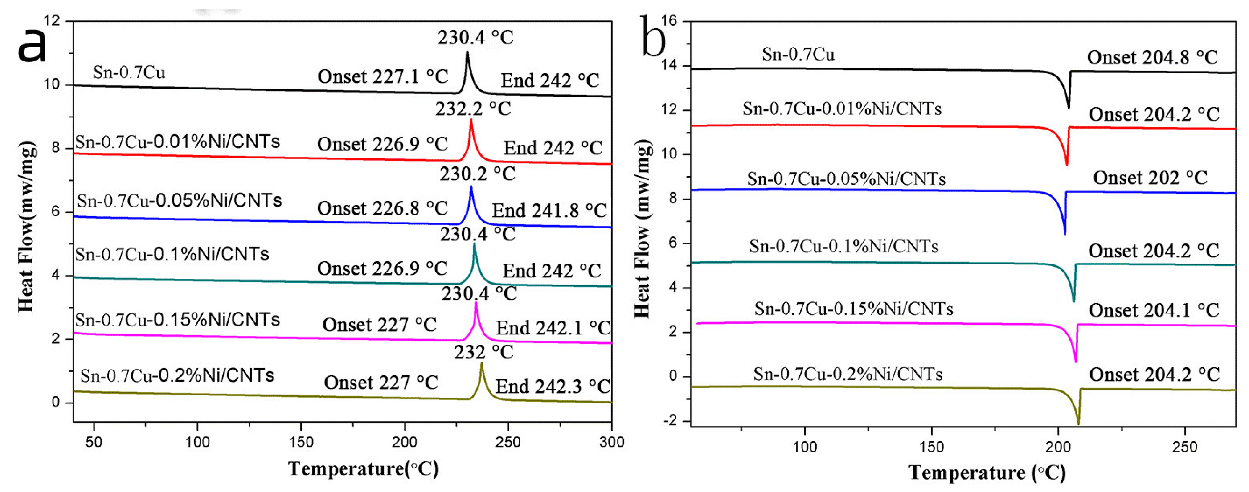
3.3. Solder Melting Point

Figure 5 shows the DSC curves of the samples reinforced with Ni-coated CNTs. Figure 5a gives the endothermic curve and Figure 5b is the exothermic curve, where from top to bottom are the DSC curves of Sn-0.7Cu-xNi/CNTs solders (x = 0, 0.01, 0.05, 0.1, 0.15 and 0.2), with only one peak in all cases. For the composite solder that has a certain melting point, the onset temperature (Tonset) reflects the beginning of the melting process and is regarded as the melting temperature. The peak temperature (Tpeak) indicates the end of the melting process. It can be seen from Figure 5a, without adding Ni-coated CNTs, that the melting point of Sn-0.7Cu is 227.4 °C, which is close to that of the eutectic solder Sn-0.7%Cu. The melting points of Sn-0.7Cu-xNi/CNTs solders (x = 0.01, 0.05, 0.1, 0.15, 0.2) are 226.9 °C, 226.8 °C, 226.9 °C, 227.0 °C and 227.0 °C, which are slight lower than that of eutectic solder Sn-0.7%Cu. The melting point reaches the lowest with the addition of 0.05 wt.% Ni-coated CNTs. Similarly, it is observed that the Tpeak are 230.4 °C, 232.0 °C, 230.2 °C, 230.4 °C, 23.4 °C and 232.0 °C. Accordingly, the melting intervals were 3.3, 5.1, 3.4, 3.5, 3.4 and 5 in sequence, which are relatively small and suitable for practical applications. In addition, the undercooling is measured from the DSC curves of the composite solder. It is notable that, with the addition of 0.05 wt.% Ni-coated CNTs, the undercooling increased from 19.3 °C to 21.8 °C. However, the undercooling decreased to 19.8 °C when 0.2 wt.% Ni-coated CNTs were added. With high undercooling, the nucleation rate increased much faster than that of the nucleation, so the finer grain could be obtained, which coincided with the refinement of the microstructure of the composite solders.

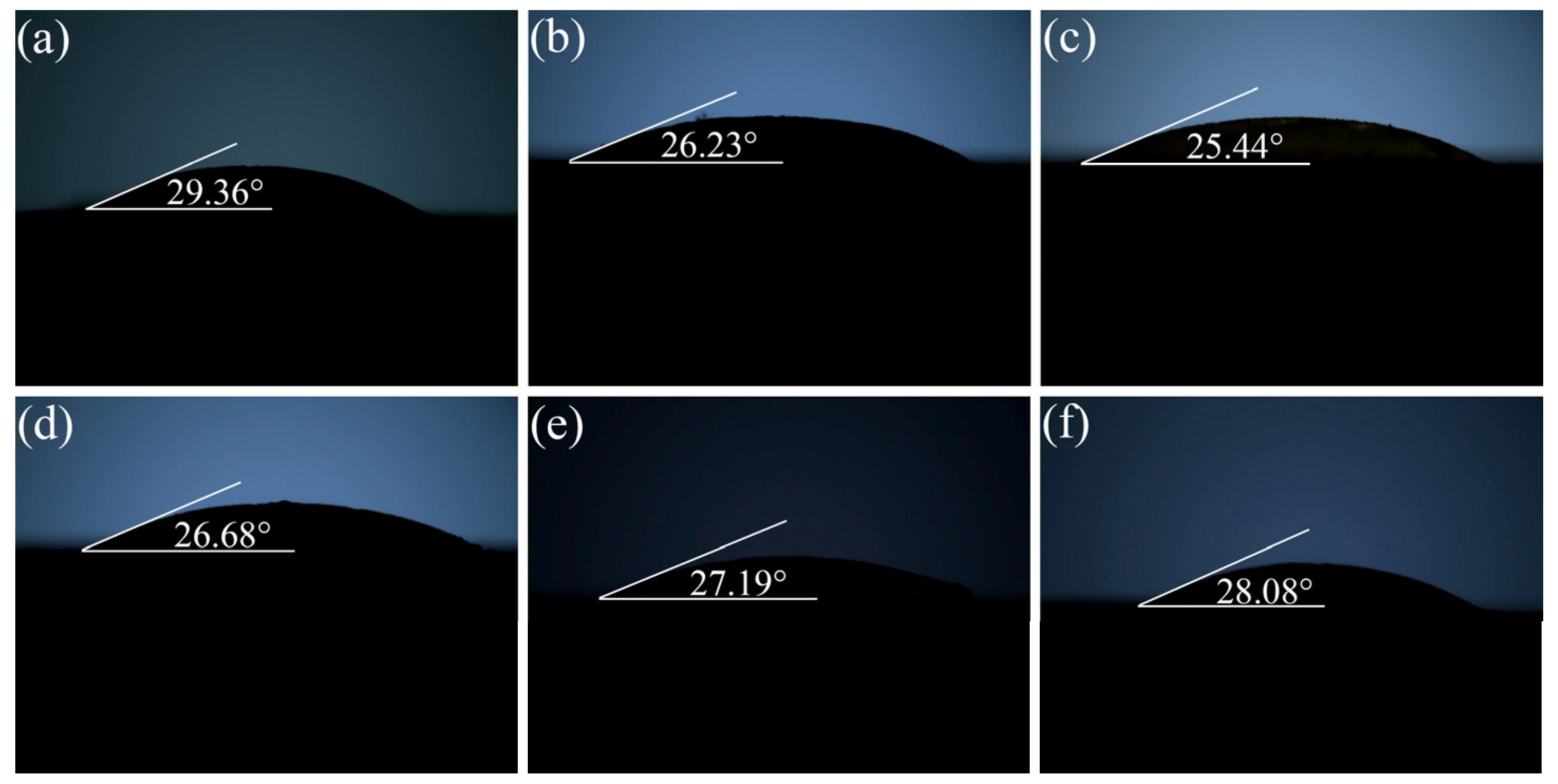
3.4. Solder Wettability

Figure 6 shows the variations of the wetting angle of Sn-0.7Cu-xNi/CNTs solders on Cu substrates reflowed at 280 °C for 5 min as a function of Ni-coated CNTs content. As shown in Figure 6, the wetting angle decreases with the Ni-coated CNTs content and reaches the minimum at 0.05 wt.%, and thereafter it increases. The wetting angle of the composite solders was always less than that of the Sn-0.7Cu solder. With the addition of 0.05 wt.% Ni-coated CNTs, the wetting angle decreased by 13.35%, and an optimum wetting angle of 25.44° was achieved. This could be attributed to the lower surface-interfacial energy when Ni-coated CNTs reinforcement was used. However, when more Ni-coated CNTs were added from 0.1 wt.% to 0.2 wt.%, the wetting angle increased. This could be due to the aggregation and uneven distribution of a large number of Ni-coated CNTs, hindering the melting of solder flow. Han et al. [28] reported that the addition of Ni-coated CNTs into Sn-Ag-Cu solder in the amount of 0.05–0.1 wt.% effectively reduced the contact angle, while the addition of Ni-coated CNTs (0.3 wt.%) increased the contact angle. Therefore, the addition of the reinforcement phase should be moderate. Moreover, it could be seen that a lower melting point was beneficial to the wettability of the solder.

4. Conclusions

Both Ni and Ni2P particles were coated on the surface of the carbon nanotubes by improved electroless nickel plating. The microstructure of the composite solder was still composed of the intermetallic compound Cu6Sn5 in the β-Sn matrix with the addition of Ni-coated CNTs. When 0.05 wt.% Ni-coated CNTs were added, the rod-shaped Cu6Sn5 particles disappeared, and all appeared in a form of dot-shaped Cu6Sn5 particles. However, the dot-shaped Cu6Sn5 particles decreased while the coarsened rod-shaped Cu6Sn5 particles increased in quantity with a Ni-coated CNTs concentration from 0.1 wt.% to 0.2 wt.% The melting characteristics of the composite solders were observed to be slightly decreased with the addition of Ni-coated CNTs. The melting point reached the lowest with the addition of 0.05 wt.% Ni-coated CNTs. The wetting angle was used to characterize the wettability of the composite solders. The wetting angle of the composite solders was always less than that of the Sn-0.7Cu solder, indicating an improvement in the wettability. With the addition of 0.05 wt.% Ni-coated CNTs, the wetting angle decreased by 13.35%, and an optimum wetting angle of 25.44° was achieved.

Author Contributions

Conceptualization, X.L. and Z.J.; methodology, X.L. and Z.J.; validation, X.L. and J.W.; formal analysis, X.L. and Z.J.; investigation, G.L.; resources, C.Y. and F.W.; data curation, X.L. and G.L.; writing—original draft preparation, X.L.; writing—review and editing, X.L. and G.L.; supervision, J.W.; project administration, F.W. All authors have read and agreed to the published version of the manuscript.

Funding

This research received no external funding.

Institutional Review Board Statement

Not applicable.

Informed Consent Statement

Not applicable.

Data Availability Statement

Not applicable.

Conflicts of Interest

The authors declare no conflict of interest.

References

  1. Xiao, Q.; Bailey, H.J.; Armstrong, W.D. Aging effects on microstructure and tensile property of Sn3.9Ag0.6Cu solder alloy. J. Electron. Packag. 2004, 126, 208–212. [Google Scholar] [CrossRef]
  2. Nguyen, V.L.; Kim, S.H.; Jeong, J.W.; Lim, T.-S.; Yang, D.-Y.; Kim, K.B.; Kim, Y.J.; Lee, J.H.; Kim, Y.-J.; Yang, S. Microstructure and mechanical behavior of low-melting point Bi-Sn-In solder joints. Electron. Mater. Lett. 2017, 13, 420–426. [Google Scholar] [CrossRef]
  3. Dele-Afolabi, T.T.; Azmah Hanim, M.A.; Norkhairunnisa, M.; Yusoff, H.M.; Suraya, M.T. Growth kinetics of intermetallic layer in lead-free Sn–5Sb solder reinforced with multi-walled carbon nanotubes. J. Mater. Sci. Mater. Electron. 2015, 26, 8249–8259. [Google Scholar] [CrossRef]
  4. Zhong, X.L.; Gupta, M. Development of lead-free Sn–0.7Cu/Al2O3nanocomposite solders with superior strength. J. Phys. D Appl. Phys. 2008, 41, 095403. [Google Scholar] [CrossRef]
  5. Gain, A.K.; Zhang, L.; Chan, Y.C. Microstructure, elastic modulus and shear strength of alumina (Al2O3) nanoparticles-doped tin–silver–copper (Sn–Ag–Cu) solders on copper (Cu) and gold/nickel (Au/Ni)-plated Cu substrates. J. Mater. Sci. Mater. Electron. 2015, 26, 7039–7048. [Google Scholar] [CrossRef]
  6. Tsao, L.C.; Huang, C.H.; Chung, C.H.; Chen, R.S. Influence of TiO2 nanoparticles addition on the microstructural and mechanical properties of Sn0.7Cu nano-composite solder. Mater. Sci. Eng. A 2012, 545, 194–200. [Google Scholar] [CrossRef]
  7. Yang, L.; Zhang, Y.; Dai, J.; Jing, Y.; Ge, J.; Zhang, N. Microstructure, interfacial IMC and mechanical properties of Sn–0.7Cu–xAl (x = 0–0.075) lead-free solder alloy. Mater. Des. 2015, 67, 209–216. [Google Scholar] [CrossRef]
  8. Tsao, L.C.; Chang, S.Y. Effects of Nano-TiO2 additions on thermal analysis, microstructure and tensile properties of Sn3.5Ag0.25Cu solder. Mater. Des. 2010, 31, 990–993. [Google Scholar] [CrossRef]
  9. Gain, A.K.; Chan, Y.C.; Yung, W.K.C. Microstructure, thermal analysis and hardness of a Sn–Ag–Cu–1wt% nano-TiO2 composite solder on flexible ball grid array substrates. Microelectron. Reliab. 2011, 51, 975–984. [Google Scholar] [CrossRef]
  10. Sun, R.; Sui, Y.; Qi, J.; Wei, F.; He, Y.; Chen, X.; Meng, Q.; Sun, Z. Influence of SnO2 Nanoparticles Addition on Microstructure, Thermal Analysis, and Interfacial IMC Growth of Sn1.0Ag0.7Cu Solder. J. Electron. Mater. 2017, 46, 4197–4205. [Google Scholar] [CrossRef]
  11. El-Daly, A.A.; Fawzy, A.; Mansour, S.F.; Younis, M.J. Novel SiC nanoparticles-containing Sn–1.0Ag–0.5Cu solder with good drop impact performance. Mater. Sci. Eng. A 2013, 578, 62–71. [Google Scholar] [CrossRef]
  12. Kumar, K.M.; Kripesh, V.; Tay, A.A.O. Single-wall carbon nanotube (SWCNT) functionalized Sn–Ag–Cu lead-free composite solders. J. Alloy. Compd. 2008, 450, 229–237. [Google Scholar] [CrossRef]
  13. Nai, S.M.L.; Wei, J.; Gupta, M. Improving the performance of lead-free solder reinforced with multi-walled carbon nanotubes. Mater. Sci. Eng. A 2006, 423, 166–169. [Google Scholar] [CrossRef]
  14. Iijima, S. Helical microtubes of graphitic carbon. Nature 1991, 354, 56–58. [Google Scholar] [CrossRef]
  15. Shao, H.; Chen, B.; Li, B.; Tang, S.; Li, Z. Influence of dispersants on the properties of CNTs reinforced cement-based materials. Constr. Build. Mater. 2017, 131, 186–194. [Google Scholar] [CrossRef]
  16. Svatoš, V.; Sun, W.; Kalousek, R.; Gablech, I.; Pekárek, J.; Neužil, P. Single Measurement Determination of Mechanical, Electrical, and Surface Properties of a Single Carbon Nanotube via Force Microscopy. Sens. Actuators A Phys. 2018, 271, 217–222. [Google Scholar] [CrossRef]
  17. Esawi, A.M.K.; El Borady, M.A. Carbon nanotube-reinforced aluminium strips. Compos. Sci. Technol. 2008, 68, 486–492. [Google Scholar] [CrossRef]
  18. Guerret-Piécourt, C.; Bouar, Y.; Lolseau, A.; Pascard, H. Relation between metal electronic structure and morphology of metal compounds inside carbon nanotubes. Nature 1994, 372, 761–765. [Google Scholar] [CrossRef]
  19. Prem Kumar, T.; Ramesh, R.; Lin, Y.Y.; Fey, G.T.-K. Tin-filled carbon nanotubes as insertion anode materials for lithium-ion batteries. Electrochem. Commun. 2004, 6, 520–525. [Google Scholar] [CrossRef]
  20. Zhang, F.; Li, J.; Wang, T.; Huang, C.; Ji, F.; Shan, L.; Zhang, G.; Sun, R.; Wong, C.P. Fluorinated graphene/polyimide nanocomposites for advanced electronic packaging applications. J. Appl. Polym. Sci. 2020, 138, 49801. [Google Scholar] [CrossRef]
  21. Chantaramanee, S.; Wisutmethangoon, S.; Sikong, L.; Plookphol, T. Development of a lead-free composite solder from Sn–Ag–Cu and Ag-coated carbon nanotubes. J. Mater. Sci. Mater. Electron. 2013, 24, 3707–3715. [Google Scholar] [CrossRef]
  22. Song, H.-Y.; Zha, X.-W. Mechanical properties of nickel-coated single-walled carbon nanotubes and their embedded gold matrix composites. Phys. Lett. A 2010, 374, 1068–1072. [Google Scholar] [CrossRef]
  23. Liu, H.; Cheng, G.; Zheng, R.; Zhao, Y.; Liang, C. Influence of synthesis process on preparation and properties of Ni/CNT catalyst. Diam. Relat. Mater. 2006, 15, 15–21. [Google Scholar] [CrossRef]
  24. Kong, F.Z.; Zhang, X.B.; Xiong, W.Q.; Liu, F.; Huang, W.Z.; Sun, Y.L.; Tu, J.P.; Chen, X.W. Continuous Ni-layer on multiwall carbon nanotubes by an electroless plating method. Surf. Coat. Technol. 2002, 155, 33–36. [Google Scholar] [CrossRef]
  25. Wang, F.; Arai, S.; Endo, M. Preparation of nickel–carbon nanofiber composites by a pulse-reverse electrodeposition process. Electrochem. Commun. 2005, 7, 674–678. [Google Scholar] [CrossRef]
  26. Ma, X.; Li, X.; Lun, N.; Wen, S. Synthesis of gold nano-catalysts supported on carbon nanotubes by using electroless plating technique. Mater. Chem. Phys. 2006, 97, 351–356. [Google Scholar] [CrossRef]
  27. Zhao, B.; Yadian, B.L.; Li, Z.J.; Liu, P.; Zhang, Y.F. Improvement on wettability between carbon nanotubes and Sn. Surf. Eng. 2013, 25, 31–35. [Google Scholar] [CrossRef]
  28. Han, Y.D.; Nai, S.M.L.; Jing, H.Y.; Xu, L.Y.; Tan, C.M.; Wei, J. Development of a Sn–Ag–Cu solder reinforced with Ni-coated carbon nanotubes. J. Mater. Sci. Mater. Electron. 2010, 22, 315–322. [Google Scholar] [CrossRef]
  29. Song, Y.; Sun, Z.; Xu, L.; Shao, Z. Preparation and Characterization of Highly Aligned Carbon Nanotubes/Polyacrylonitrile Composite Nanofibers. Polymers 2017, 9, 1. [Google Scholar] [CrossRef] [Green Version]
Figure 1. Schematic diagram of solders spreading area specimen: (a) top view and (b) side view.
Metals 12 01196 g001
Figure 2. Ni-coated carbon nanotubes: (a) XRD pattern, (b) SEM images, (c) TEM images, (d) HR-TEM images.
Metals 12 01196 g002
Figure 3. FE-SEM microstructure of polished surfaces of the composite solder Sn-0.7Cu-xNi/CNTs, (a) x = 0, (b) x = 0.01, (c) x = 0.05, (d) x = 0.1, (e) x = 0.15, (f) x = 0.2.
Metals 12 01196 g003
Figure 4. (a) SEM image of the IMC Cu6Sn5, (b) EDS analysis of different points of IMC Cu6Sn5, (c) SEM image and (d) elemental.
Metals 12 01196 g004
Figure 5. Melting and solidification properties of the composite solders, (a) DSC heating curves, (b) DSC cooling curves.
Metals 12 01196 g005
Figure 6. Wetting angle of the composite solder Sn-0.7Cu-xNi/CNTs, (a) 0%, (b) 0.01%, (c) 0.05%, (d) 0.1%, (e) 0.15% and (f) 0.2%.
Metals 12 01196 g006
Publisher’s Note: MDPI stays neutral with regard to jurisdictional claims in published maps and institutional affiliations.

