Article

Corrosion Behavior of Ancient White Cast Iron Artifacts from Marine Excavations at Atmospheric Condition

1
School of Archaeology and Museology, Peking University, Beijing 100871, China
2
Beijing Engineering Research Center of Radiographic Techniques and Equipment, Institute of High Energy Physics, Chinese Academy of Sciences, Beijing 100049, China
3
National Centre for Archaeology, Beijing 100013, China
4
Guangdong Provincial Institute of Cultural Relics and Archaeology, Guangzhou 510075, China
*
Author to whom correspondence should be addressed.
Metals 2022, 12(6), 921; https://doi.org/10.3390/met12060921
Submission received: 30 April 2022 / Revised: 20 May 2022 / Accepted: 23 May 2022 / Published: 27 May 2022
(This article belongs to the Special Issue Metals for Art and Cultural Heritage)

Abstract

:
A large number of iron pot artifacts were excavated from the “Nanhai I” shipwreck. The rapid embrittlement and pulverization of these objects (that have a good matrix) in the atmospheric environment is worthy of attention. Metallographic analysis showed that the material of the iron pots was hypereutectic white cast iron. Micro-CT observations revealed that there were numerous microcracks and fissures within the seemingly well-preserved iron. These fissures increased and enlarged with prolonged exposure to air. Scanning electron microscopy exhibited that the microcracks were initially created at the “concave surface” formed by the ferrite corrosion, and the cementite was gradually torn by the local accumulation of large internal stresses. Micro-Raman proved that the structure of rust was varied and complex during the generation and development of fissures. The dimension of corrosion products could expand and contract in mutual transformation, forming local internal stress and promoting the expansion of microcracks. This work proposed a reasonable mechanism for the rapid embrittlement and pulverization in the atmospheric environment of such hypereutectic white cast iron artifacts out of the sea, which provided a scientific reference for future protection.

1. Introduction

Numerous historical and cultural heritages are buried under the sea. According to incomplete statistics, more than 3 million shipwrecks are undiscovered across the world, bearing witness to every chapter of history [1]. Meanwhile, iron artifacts constitute an important component of underwater archaeological discoveries. As seawater is a highly complex environment with a strong corrosive impact, iron artifacts are subjected to severe corrosion within it.
Many research indicate that rust delamination of iron artifacts from the surface to inner metal is quite common and shows certain patterns [2,3]. The rust is often divided into two or three layers [4,5]. The inner layer is mainly composed of magnetite, while the outer layer is composed of iron oxides and iron hydroxyl oxides, and the outermost layer is a hard crust [6]. Meanwhile, corrosion products generated in marine environment are usually unstable. The transformation between different rusts is constantly occurring [7,8]. The stabilization treatment of the surface rust layer is the key research aim of iron artifact protection at present. However, with the salvage of the “Nanhai I” shipwreck in China, a rare corrosion behavior of archaeological iron artifacts in marine environment is discovered, which poses a new challenge to the protection of marine iron artifacts.
The “Nanhai I” is the largest, oldest, and most completely preserved merchant ship excavated from the marine environment in China [9]. It is of great significance to the study of trade exchanges along the ancient Chinese Maritime Silk Road [10]. Many archaeological iron artifacts were excavated from the “Nanhai I” shipwreck, such as iron pots, iron nails, etc. They are important physical evidence for the study of iron smelting technology and material trade in China during the Song Dynasty [11]. However, if the iron pot artifacts are not properly protected in time, the special corrosion phenomenon of embrittlement and pulverization will rapidly occur after exposure to the atmosphere. Due to the chemical activity of iron and the strong corrosive nature of the marine environment, the iron artifacts will generally be seriously corroded and mineralized [12,13,14]. Because of the special burial condition of the “Nanhai I” shipwreck and the storage of the iron pot artifacts in the cabin, many iron pot artifacts excavated from seawater have a well-preserved iron matrix. However, they could still embrittle and pulverize quickly in atmospheric conditions, and the original shape of these iron pot artifacts would no longer exist.
In general, the generation of loose akageneite under chlorine-rich conditions is the typical corrosion feature of iron artifacts excavated from marine water [15,16]. Consequently, the rust layer cracks and begins to peel from the outside to the inside. For iron artifacts, they will first lose the artifact information of the outermost layer, and this will gradually spread to the inside matrix. However, the corrosion phenomenon of the “Nanhai I” iron pot artifacts is different. It is an extremely rare occurrence for such artifacts to become embrittled and pulverized during the corrosion process, namely in the following aspects. Firstly, the whole iron pots become brittle and pulverized. The overall embrittlement and pulverization of the iron pot artifacts will not only ruin the information of material composition, smelting technology, and corrosion characteristics, but also cannot retain the whole shape of the artifacts. Secondly, the speed of iron pot embrittled pulverization is very fast; the corrosion rate of iron artifacts from the sea is about 10 times higher than at atmospheric condition [17], measured in decades. This indicates that the corrosion rate in the atmospheric environment is much lower than in the marine environment. However, this was not the case for the iron pot samples of the “Nanhai I” shipwreck extracted from the desalination solution when they were exposed to the atmospheric condition. The cutting section of these samples showed good metallic luster, but then cracked in 2–3 days at the most. Many wide and deep cracks were produced, and overall pulverization occurred after several months. Moreover, the traditional methods of desalination [18,19,20], tannic acid corrosion inhibition [21], and microcrystalline wax sealing protection [22,23,24] could slow down the pulverization rate to some extent, but could not prevent the pulverization from occurring. Therefore, the iron pot samples were more demanding in terms of protection materials and treatment processes.
Thus, the corrosion phenomenon of embrittlement and pulverization of iron pot artifacts from the “Nanhai I” shipwreck is very special. It is the complex combined effect of marine and atmospheric environments. This special corrosion phenomenon needs more attention from researchers. It is important to find out the rapid corrosion behavior of iron pot artifacts and investigate the mechanism of embrittlement and pulverization to ensure future protection.

2. Materials and Methods

The samples were iron pot fragments taken from the desalination pond of the Maritime Silk Road Museum of Guangdong, and the desalination solution was 1.0% (mass ratio) NaOH solution. The embrittlement and pulverization behaviors of iron pot artifacts were observed in an atmospheric environment in room condition. The temperature was 20–25 °C and the relative humidity was 45–55%.
The analytical instruments used for the study are listed below:
Metallographic microscope: After cutting, embedding, and pre-grinding, the tested surface was ground with #180, #300, #600, #1000, #1200, #1500, #2000, and #3000 sandpaper for later polishing. The iron pot samples were observed under a metallographic microscope (Eclipse LV100ND, Nikon, Tokyo, Japan), mainly to observe the composition of the phase of the samples and the distribution of the presence of microcracks and cracks.
Scanning electron microscope/energy dispersive spectroscopy (SEM-EDS): The morphology and elemental distribution at the surface corrosion layer of the iron pot artifact samples and internal cracks in the matrix were analyzed and observed using SEM with energy spectrometer (Quattro ESEM, Thermo Fisher, Waltham, MA, USA) in scanning voltages of 10 kV and 15 kV and high vacuum conditions.
Micro Raman spectroscopy: The composition of corrosion products in rust layers and fissures was analyzed by using a micro-Raman imaging spectrometer (Thermo Scientific DXRxi, Thermo Fisher Scientific, Waltham, MA, USA). A bright and dark field illumination microscope (OLYMPUS BX51, Olympus Corporation, Tokyo, Japan) with a 10× eyepiece and 50× objective lens was used. The laser wavelength was 532 nm, Raman shift was from 50 cm−1 to 3400 cm−1, laser intensity was 1.0 mW, exposure time was 0.5 s, and the number of scans was 300.
Computed tomography (CT): micro-CT (160 kV micro-CT, Institute of High Energy Physics, Chinese Academy of Sciences, Beijing, China) were used to detect the distribution and development of internal fissures in the matrix of iron pot samples. The test conditions were: high resolution scanning mode, tube voltage 100 kV, power 2 W, projection number 720 with two frames superimposed in each.

3. Results and Discussion

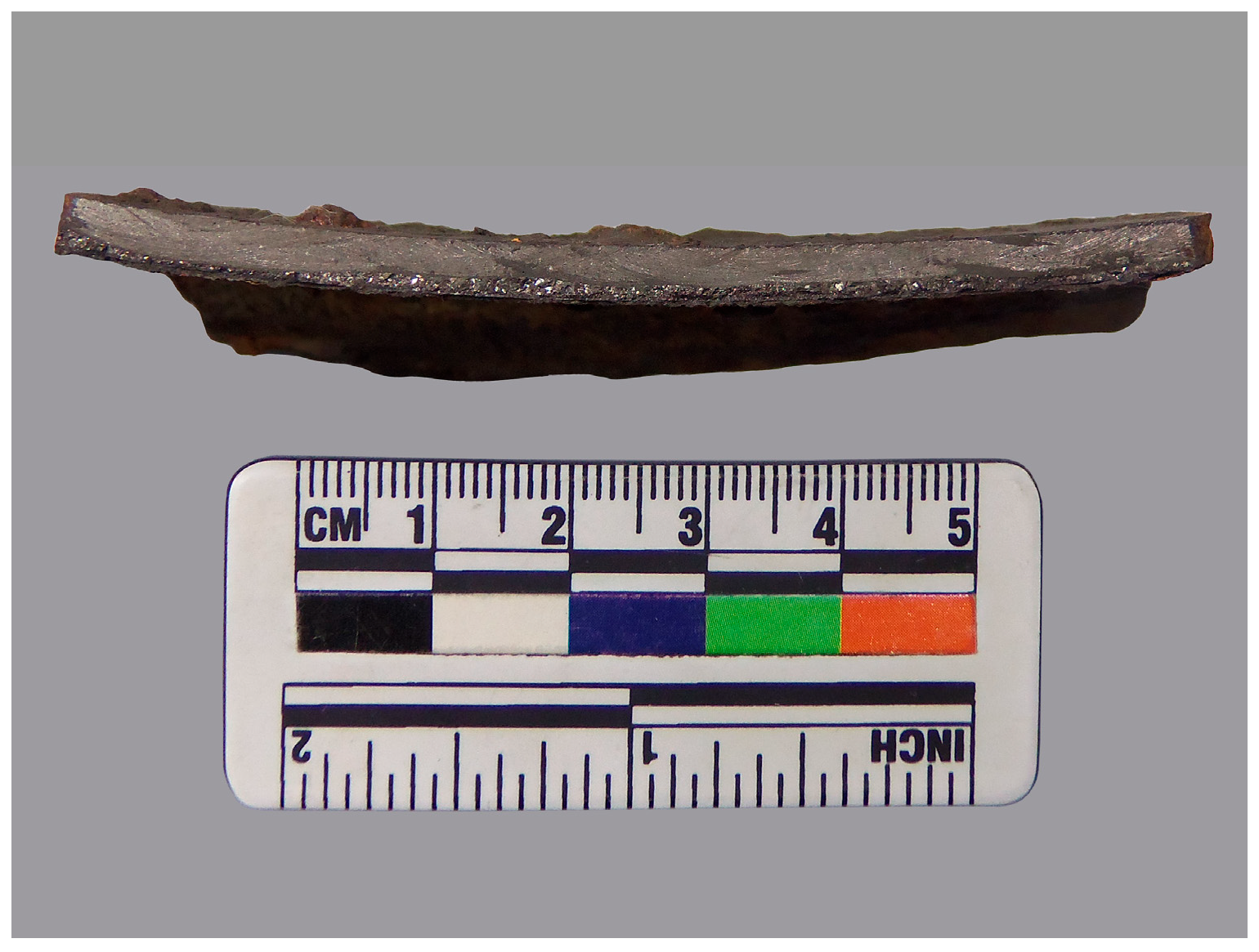
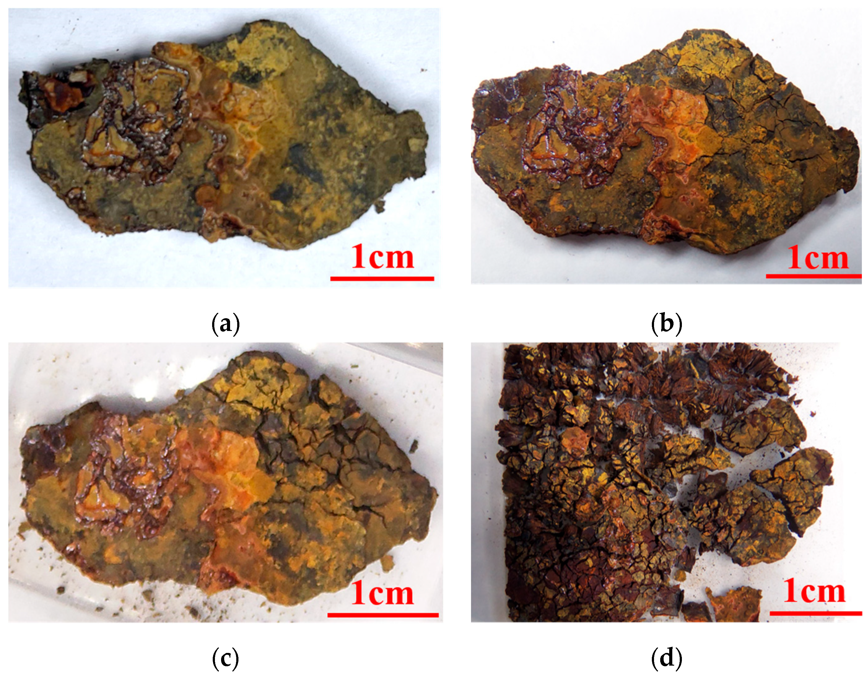
3.1. Phenomenon of Embrittlement and Pulverization

Iron pot samples were all taken from the desalination pond, and Figure 1 shows a cross-section of a representative piece of the iron pot samples. As can be seen in Figure 1, the sample was covered with thick rust on both sides of its surface. The center of the iron matrix was well-preserved with a bright silver-white metallic luster, which indicated that these iron samples still have physical strength.
When the samples are placed in the atmosphere, most of them will corrode rapidly, and the phenomenon of embrittled pulverization usually occurs rapidly after a few weeks or 2–3 months. Figure 2a–d shows the rapid pulverization behavior of iron pot fragments for 90 days. As can be seen from the photos, the sample had a well-preserved iron matrix and a bright silvery-white metallic luster in the cutting section. After being removed from the desalination pond and placed in the atmosphere, the corrosion rate was very fast, and embrittled pulverization of iron pot samples occurred rapidly in a few months. The pulverization behavior was: The initial state was the whole sample, which had a well-preserved iron matrix and high mechanical strength. Fifteen days later, the upper-right corner of the external surface formed a small number of local cracks. The cracks were narrow and shallow, and the sample shape remained intact and maintained a certain mechanical strength. After 30 days, the cracks had further developed to become wider, denser, and deeper, and the edge of part of the fragments had a tendency to scatter away from the whole sample. After 90 days, the sample was pulverized into small pieces and lost its overall shape.

3.2. Materials and Corrosion Micromorphology of the Iron Pot

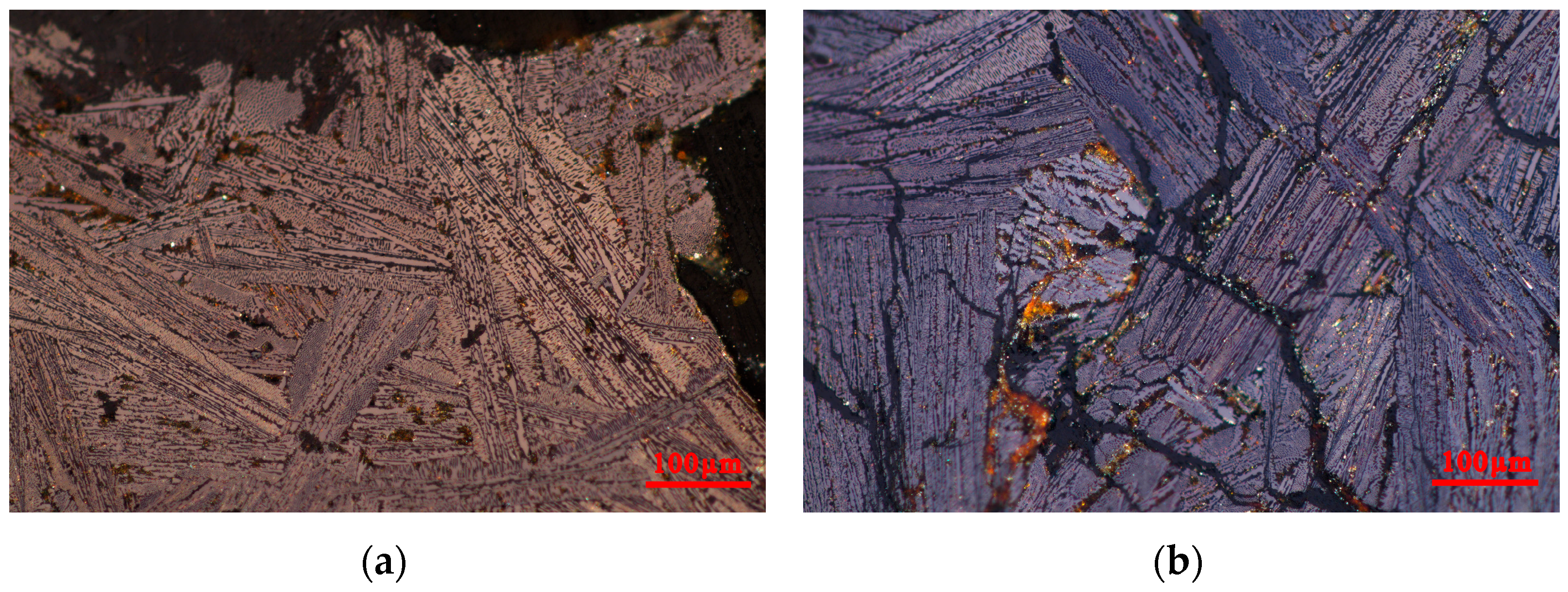
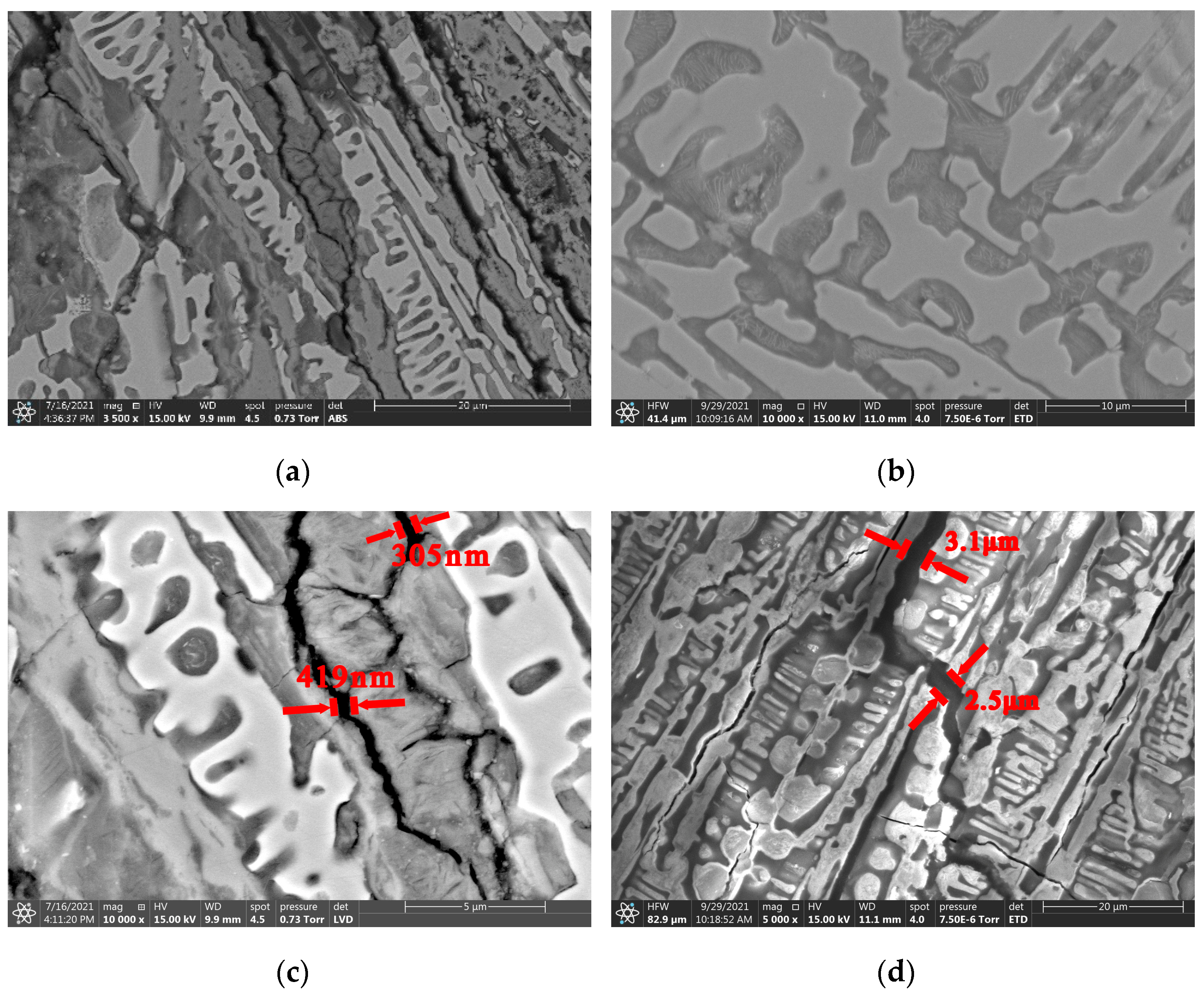
3.2.1. Materials of the Iron Pot

Figure 3 showed the metallographic results of the iron pot artifacts from the “Nanhai I” shipwreck; it can be seen from Figure 3a that the iron pot was a typical hypereutectic white cast iron with eutectic ledeburite and primary cementite, and the phase was ferrite and cementite. The bright area consisted of uncorroded cementite, where the bright long striped phase was proeutectic cementite, and the dark area mainly consisted of corroded ferrite. Meanwhile, as can be seen from Figure 3b, the sample matrix had many corrosion strips and microcracks. There were two main states of microcracks: the first was developing and extending along the boundary of the crystal particle; the other was directly penetrating through the crystal particles in a random direction distribution. Most of the microcracks belonged to the latter state, and microcracks directly tore the crystal particles.

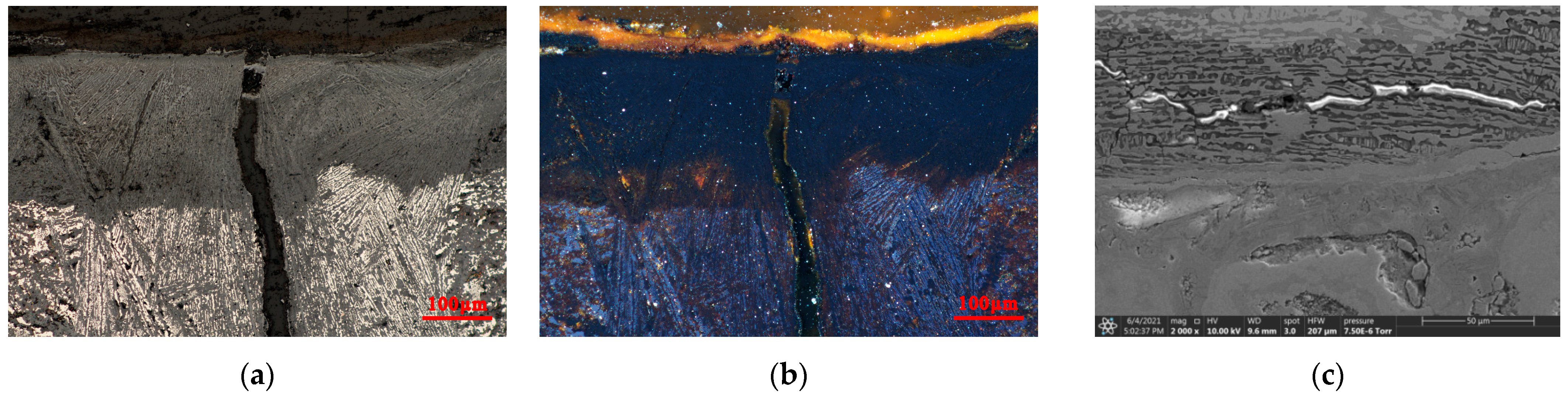
3.2.2. Micromorphology of Inner Cracks of the Iron Pot

The cross-sectional morphology of the iron pot sample was observed using metallographic microscopy and scanning electron microscopy, as shown in Figure 4. Figure 4a,b show the metallographic photographs of the cross-section of the sample under brightfield and brightfield with polariscope. According to the corrosion degree from deep to shallow, the sample could be divided into three areas from outside to inside: the rust zone, the heavy corrosion zone, and the slight corrosion zone. The outermost metal matrix was most seriously corroded and almost completely mineralized as iron rust, which was the rust zone. It could be further divided into two layers: the external rust layer that contacted the atmosphere was yellow and loose, while the internal layer that contacted the matrix was black and dense. The lower part of Figure 4a,b is the slight corrosion area, with a high percentage of bright white metal matrix and relatively mild corrosion. Ferrite corroded preferentially, while cementite corroded slightly. Between the rust layer and slight corrosion area was the heavy corrosion area. In this region, ferrite and cementite both corroded seriously. As can be seen in the dark gray region in Figure 4a, the metal matrix was not completely mineralized and still had a very small amount of bright white cementite residue. Figure 4c showed the SEM photo of the corrosion delamination of the cross-section, which showed more clearly the lower outer yellow loose rust layer, and a very thin black dense inner rust layer between the outer rust layer and the heavy corrosion area. The upper loose rust layer was the heavy corrosion area; ferrite and cementite were both corroded seriously, resulting in many “concaves”. Microcracks distributed in this area, which tore ferrite and cementite. There was a very wide fracture in the middle of the heavy corrosion area, and epoxy resin infiltrated it in the process of embedding, which shows up as bright white because of electron aggregation. The uppermost layer was the slight corrosion area, where ferrite corroded preferentially, the corrosion degree was slight, and the cementite was well-preserved. The slight corrosion area did not produce a “concave-convex” surface.
Scanning electron microscopy was used to observe the morphology and distribution of cracks in the matrix, as shown in Figure 5. In Figure 5b, the magnification was 10,000 times, and it could be clearly observed that ferrite corroded preferentially and formed the “concave surface”, where the material form was a lamellar structure. There are two possible substances corresponding to the structure of this layer. The first one is the rust product generated after oxidation corrosion of ferrite, and the second one is the carbon precipitated from ferrite during the casting cooling process. At the same time, it could be observed that the preferential corrosion of ferrite causes the cementite to form a number of vulnerable places, which were prone to cause stress concentration. During the corrosion of ferrite, α-Fe was oxidized to iron oxide or iron hydroxyl oxide, which expanded in volume and generated large internal stress locally. Microcracks were first generated at the corrosion products of ferrite, as shown in Figure 5c. The width of microcracks was about 300–400 nm. Because the cementite itself was hard and brittle, and the plasticity was almost zero, the development of microcracks would temporarily stop due to the initial development of cementite; the width of the microcracks close to the cementite was 40–50 nm. With further development of corrosion, the corrosion products in microcracks continued to transform. The volume of the corrosion products further expanded or shrinked. When the volume reached a certain threshold, the cementite was torn, as shown in Figure 5d. The fracture width of the torn cementite was 300–3000 nm. Most of the microcracks and fractures developed parallel to the direction of cementite arrangement, and a few microcracks developed perpendicularly to the direction of cementite.

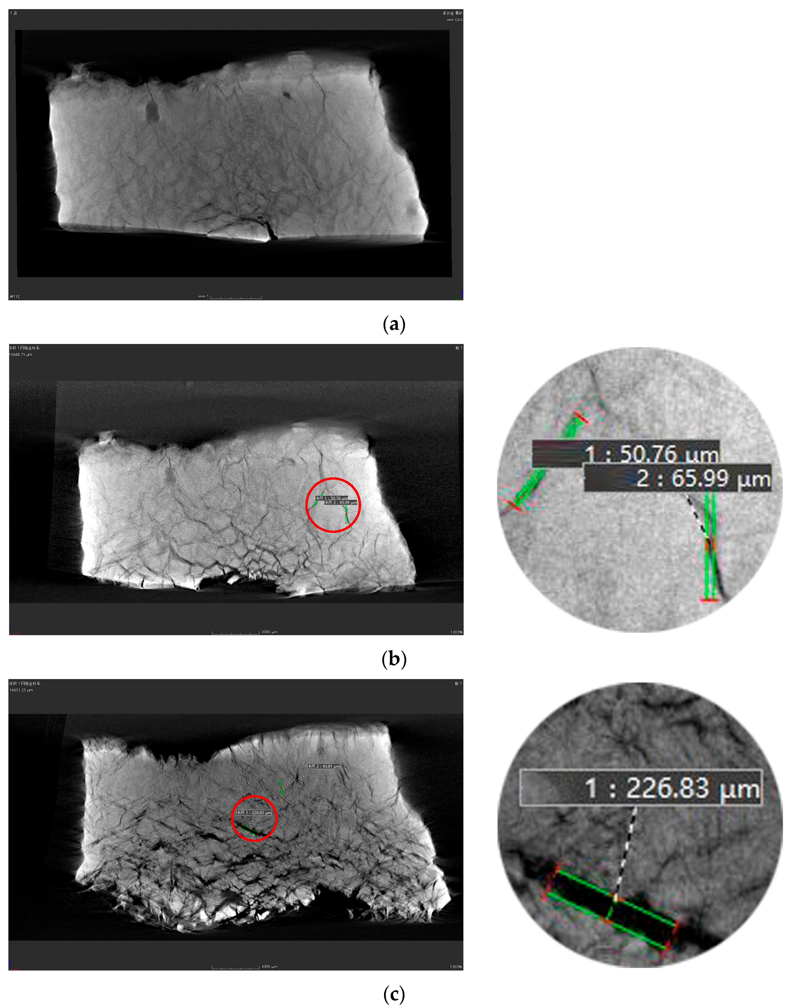
3.3. Distribution and Development of Fractures

The generation and development of microcracks in the matrix of the iron pot sample were important factors to induce the embrittlement and pulverization of the iron pot. Micro-CT was used to observe the distribution of microcracks and fissures in the sample and detected the development and change of cracks in the sample over time. The results are shown in Figure 6.
At the initial stage, when the iron pot samples were soaked in the desalination pond and placed in an atmospheric environment, the mechanical strength of the samples was higher, while the rust layer was thinner and the iron core was thicker, and the cutting section showed good silver-white metallic luster. Under micro-CT, as shown in Figure 6a, many microcracks still exist in the iron pot sample with good iron core at the initial state, and there was a defect point with expansion and warping. After 15 days, as shown in Figure 6b, cracks appeared in the bottom section of the sample, and the internal microcracks significantly increased and widened. The width of typical microcracks widened to about 50–60 μm. After 60 days, as shown in Figure 6c, the sample profile was completely pulverized and partially came off. The number of internal fractures further increased, and the width of fractures widened significantly, with some of the widest ones even reaching more than 200 μm.
It can be seen that the embrittlement and pulverization process of iron pot was closely related to the generation and development of cracks. With the development of embrittlement and pulverization of the iron pot, cracks in the matrix were increasing and widening, and the exposed area in contact with the external environment was increasing, which accelerated the corrosion process–namely, the transformation process of corrosion products in the cracks.

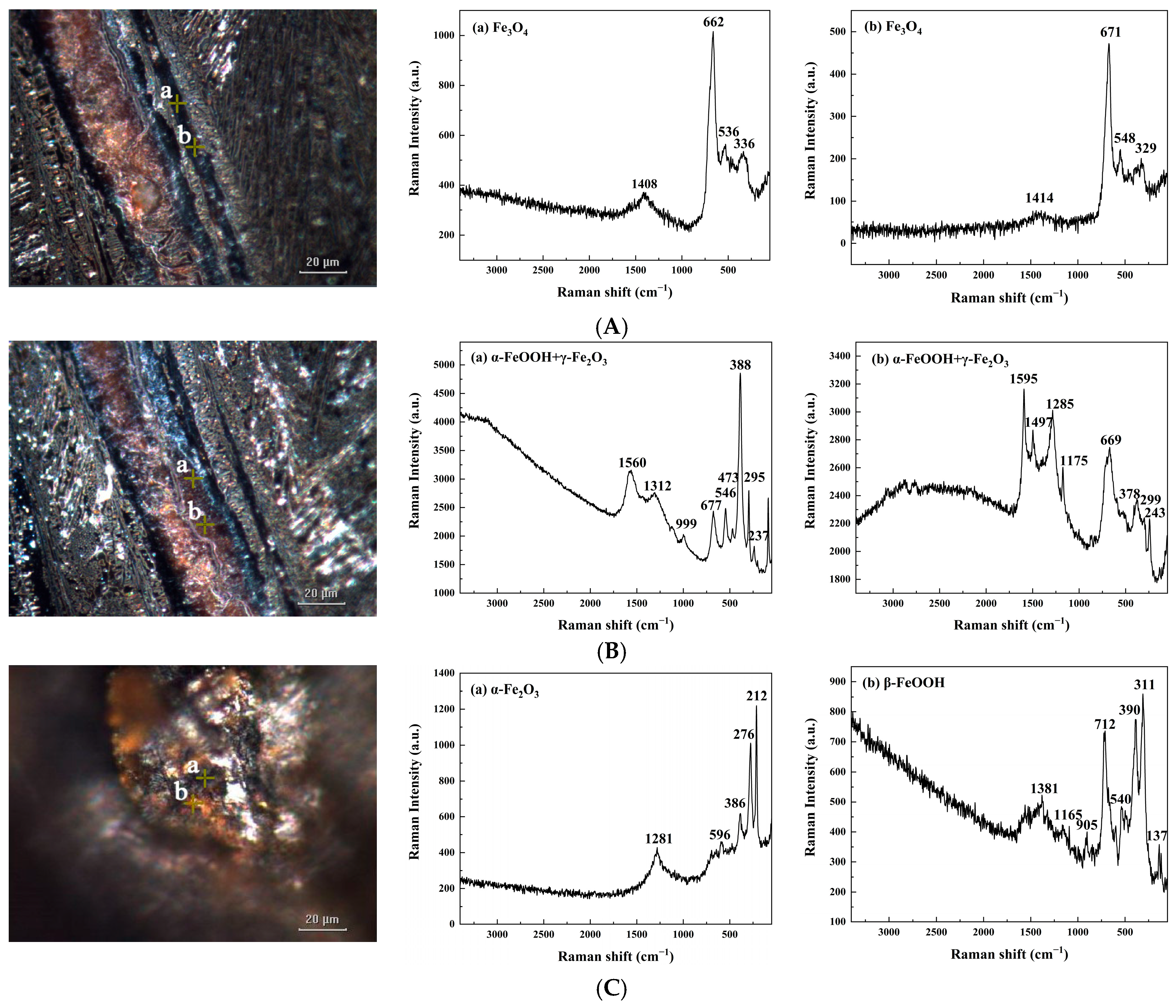
3.4. Composition and Structure of Rust in Fractures

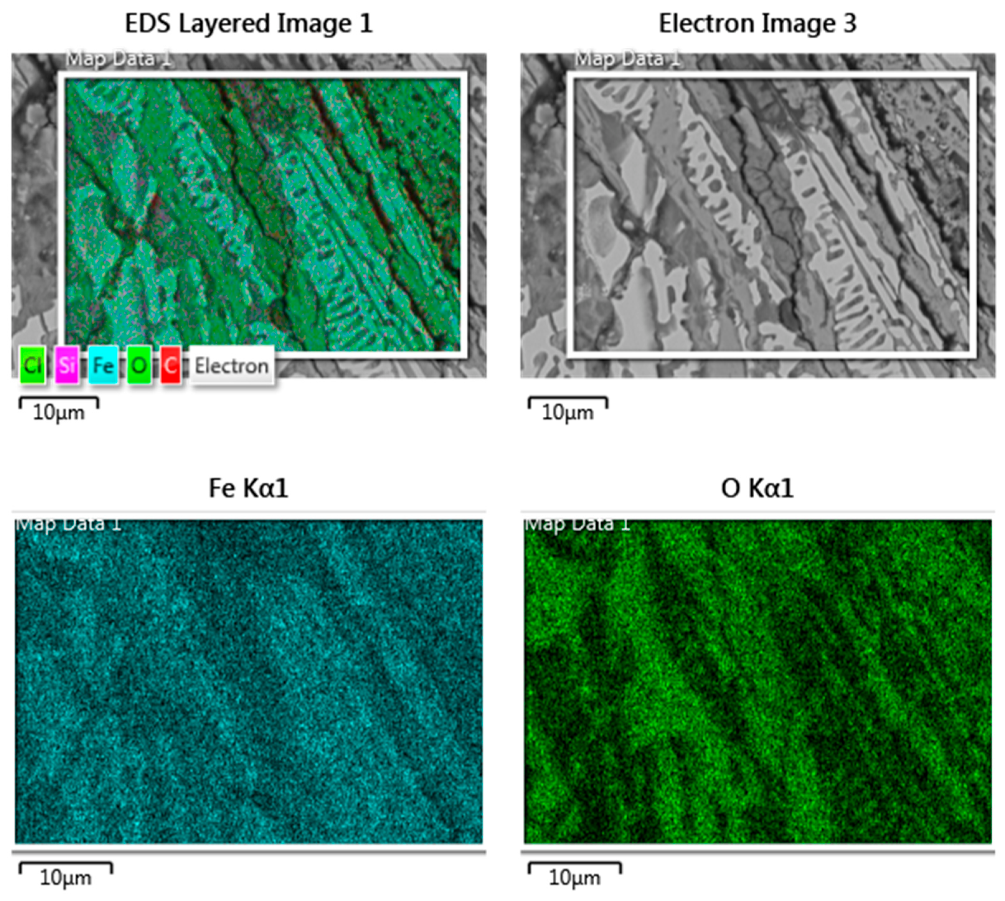
3.4.1. Component Analysis of Fractures

SEM-EDS was used to observe the matrix morphology and element distribution of internal cracks, as shown in Figure 7. It could be observed that ferrite preferentially corroded and formed many “concave surfaces”, while cementite only lightly corroded, indicating the “relative convex surface”. Most of the microcracks and fissures were distributed in the concave side where there was ferrite, and a few cracks directly tore cementite. Iron concentrated on the “relatively convex surface”, and oxygen concentrated on the “concave surface”, which was consistent with the distribution of cementite and ferrite. The content of oxygen could represent the degree of corrosion, to a certain extent. For materials of the iron artifact matrix, a high content and concentrated distribution of oxygen element represented a higher degree of corrosion, which was consistent with the fact that ferrite was more active and preferentially corroded.

3.4.2. Rust Conversion in Fracture Development

Figure 8 showed the Raman spectrum results of the phase transformation of corrosion products during the generation and development of microcracks in the matrix of the “Nanhai I” iron pot. The analysis of the Raman spectrum was based on several references [25,26]. During the corrosion process of the matrix of the iron pots, the generation and development of cracks could be divided into three stages: the single layer corrosion band in the initial stage, the double layer corrosion band in the development process, and the pulverization of the iron pot sample into small pieces with further development of cracks. In the corrosion process, the matrix was firstly oxidized into a dense Fe3O4 monolayer band, which was light gray in the bright field and black in the dark field, as shown in Figure 8A. Combined with the data of the volume expansion rate of iron oxide and hydroxyl oxide of iron in Table 1, the volume of corroded products expanded at the initial stage of fracture generation in the matrix, accumulating internal stress in the matrix and even producing microcracks. As the corrosion continued, Fe3O4 was further transformed into α-FeOOH and γ-Fe2O3, as shown in Figure 8B. The microcracks continued to expand, widen, and lengthen, and were changed into two layers. The outer layer was still a dense Fe3O4 band, and the inner layer was a loose α-FeOOH and γ-Fe2O3 mixed band, which came off easily. After the iron pot samples pulverized into small pieces, a large amount of orange corrosion was observed in the section as β-FeOOH, and the black corrosion was α-Fe2O3, as shown in Figure 8C.
It could be concluded from the microscopic Raman results that the phase transformation of rust in the process of fracture development was as follows: Fe3O4 → α-FeOOH + γ-Fe2O3 → β-FeOOH + α-Fe2O3. With the development of fissures, the composition of corrosion products at fissures was quite complex, and constantly transformed. In this process, the volume of corrosion products continuously expanded and contracted. The internal stress further accumulated, making the fissure development longer and wider.

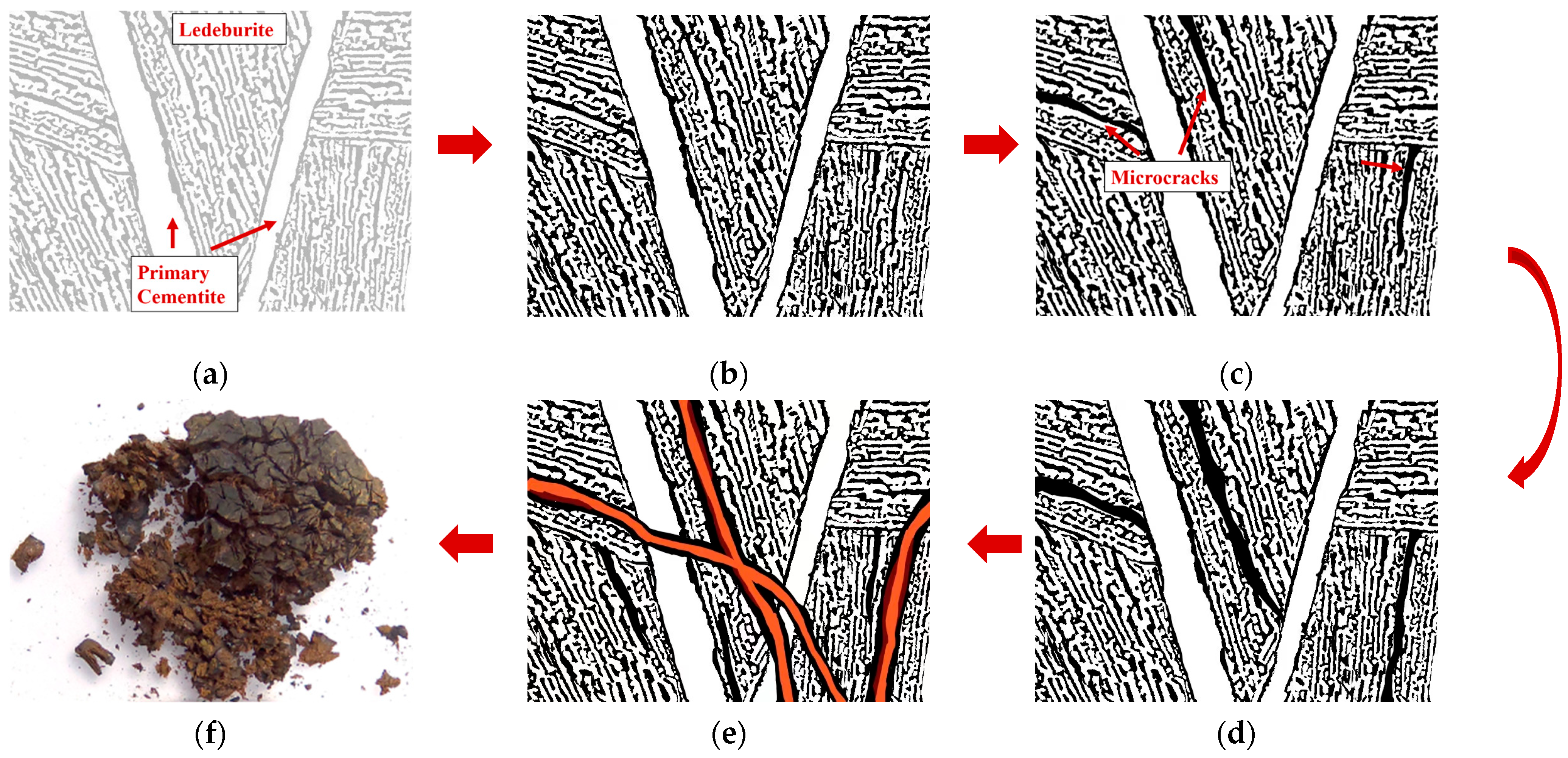
3.5. Mechanism of Corrosion Embrittlement and Pulverization

According to the existing research results, the generation and development of fissures in the process of embrittlement and pulverization of iron pot artifacts from the “Nanhai I” shipwreck could be summarized as follows.
The iron pot was hypereutectic white cast iron. The metallographic structure was eutectic ledeburite and primary cementite with the form of coarse lamellae, and the phase included ferrite and cementite. The matrix did not corrode in the initial state, as shown in Figure 9a. As the ferrite was easier to corrode compared with the cementite, in the special marine burial environment, the ferrite corroded preferentially, while the cementite corrodes slightly. The color darkened at the place where corrosion occurred, as shown in Figure 9b.
As the corrosion proceeded, single dense layer corrosion strips were formed inside the iron pot matrix, which consisted of magnetite. The corrosion strips constantly developed, growing longer and wider, and then producing microcracks, as shown in Figure 9c,d. With the development of corrosion strips, corrosion products continued to transform, and gradually formed a double layer corrosion strip. The dense outer layer was magnetite, and the inner orange to dark red loose layer was goethite and maghemite, as shown in Figure 9e. In this process, the volume of corrosion products constantly expanded, resulting in micro-zone stress. The cementite was connected into a net structure in the matrix, which was hard, brittle, and had nearly zero plasticity. Due to the hard and brittle net structure, the local internal stress constantly accumulated, and finally tore the cementite. The microcracks became longer and wider, developing into fissures.
Due to the existence of a large number of microcracks and fissures inside the matrix, more air infiltrated into the internal fissures of the matrix after the iron pot was brought out of the water, promoting not only the transformation of corrosion products in the fissures, but also the formation and development of new fissures. Meanwhile, the corrosion of the metal matrix was accelerated, and the iron pot became brittle and even pulverized.

4. Conclusions

The phenomenon of rapid embrittlement and pulverization of the iron pot artifacts from the “Nanhai I” shipwreck demonstrated a very unusual corrosion behavior of hypereutectic white cast iron.
The archaeological iron pot from the “Nanhai I” was a typical hypereutectic white cast iron with eutectic ledeburite and primary cementite. The cementite was connected into a net structure. In the marine burial environment, the ferrite surrounded by net cementite corroded preferentially. The volume of corrosion products expanded, accumulating large internal stresses locally. Because the plasticity of the cementite was almost zero, it was torn apart under stress, forming many microcracks and fissures, with wider fissures up to several microns.
After the iron pots were salvaged from the water and exposed to the atmosphere, oxygen in the air entered the fissures and promoted the development of internal fissures in the matrix. With the extension of time, corrosion formed rust strips, and corrosion products with complex structures included Fe3O4, α-FeOOH, β-FeOOH, α-Fe2O3, γ-Fe2O3, etc., in different phases. In the process of physical phase transformation, the volume of corrosion products continuously expanded and contracted. The internal stress further accumulated, making the fissure development longer and wider. More air infiltrated into the fissure, accelerating the corrosion of the matrix material, until the iron pot matrix underwent embrittlement and even pulverization.

Author Contributions

Conceptualization, P.H. and G.H.; methodology, M.J.; validation, P.H. and M.J.; investigation, M.L.; resources, J.S. and Y.C.; writing—original draft preparation, P.H.; supervision, P.H. and G.H.; project administration, D.H., J.S. and Y.C.; funding acquisition, G.H. All authors have read and agreed to the published version of the manuscript.

Funding

This research was funded by the National Key Research and Development Program of China (State assignment No. 2020YFC1522100).

Institutional Review Board Statement

Not applicable.

Informed Consent Statement

Not applicable.

Data Availability Statement

The data presented in this study are available in the article.

Acknowledgments

Thanks to Li Chen in School of Physics, Peking University, for her support of SEM and EDS in this work.

Conflicts of Interest

The authors declare no conflict of interest.

References

  1. Dillmann, P.; Watkinson, D.; Angelini, E.; Adriaens, A. Corrosion and Conservation of Cultural Heritage Metallic Artefacts; Woodhead Publishing Limited: Cambridge, UK, 2013. [Google Scholar]
  2. Remazeilles, C.; Neff, D.; Bourdoiseau, J.A.; Sabot, R.; Jeannin, M.; Refait, P. Role of previously formed corrosion product layers on sulfide-assisted corrosion of iron archaeological artefacts in soil. Corros. Sci. 2017, 129, 169–178. [Google Scholar] [CrossRef]
  3. Wang, Y.; Li, J.; Zhang, L.; Zhang, L.; Wang, Q.; Wang, T. Structure of the rust layer of weathering steel in A high chloride environment: A detailed characterization via HRTEM, STEM-EDS, and FIB-SEM. Corros. Sci. 2020, 177, 108997. [Google Scholar] [CrossRef]
  4. Refait, P.; Memet, J.B.; Bon, C.; Sabot, R.; Genin, J.M.R. Formation of the Fe(II)-Fe(III) hydroxysulphate green rust during marine corrosion of steel. Corros. Sci. 2003, 45, 833–845. [Google Scholar] [CrossRef]
  5. Garcia, K.E.; Morales, A.L.; Barrero, C.A.; Greneche, J.M. New contributions to the understanding of rust layer formation in steels exposed to a total immersion test. Corros. Sci. 2006, 48, 2813–2830. [Google Scholar] [CrossRef]
  6. Zou, Y.; Wang, J.; Zheng, Y.Y. Electrochemical techniques for determining corrosion rate of rusted steel in seawater. Corros. Sci. 2011, 53, 208–216. [Google Scholar] [CrossRef]
  7. Hoerle, S.; Mazaudier, F.; Dillmann, P.; Santarini, G. Advances in understanding atmospheric corrosion of iron. II. Mechanistic modelling of wet-dry cycles. Corros. Sci. 2004, 46, 1431–1465. [Google Scholar] [CrossRef]
  8. Remazeilles, C.; Neff, D.; Kergourlay, F.; Foy, E.; Conforto, E.; Guilminot, E.; Reguer, S.; Refait, P.; Dillmann, P. Mechanisms of long-term anaerobic corrosion of iron archaeological artefacts in seawater. Corros. Sci. 2009, 51, 2932–2941. [Google Scholar] [CrossRef]
  9. Li, N.; Chen, Y.; Shen, D. Conservation Research on Excavation Site of “Nanhai I” Shipwreck 2014–2016; Science Press: Beijing, China, 2017. [Google Scholar]
  10. Zhou, Y.; Wang, K.; Jin, Y.; Sun, J.; Cui, Y.; Hu, D. Chemical and microstructural comparison of the export porcelain from five different kilns excavated from Nanhai I shipwreck. Ceram. Int. 2019, 45, 12880–12887. [Google Scholar] [CrossRef]
  11. Wan, X.; Mao, Z.; Zhang, Z.; Li, X. Analysis of iron pans and iron nails unearthed from Nanhai I shipwreck. China Cult. Herit. Sci. Res. 2016, 2, 46–51. [Google Scholar]
  12. Wu, J.J.; Wang, P.; Zhang, D.; Chen, S.Q.; Sun, Y.; Wu, J.Y. Catalysis of oxygen reduction reaction by an iron-reducing bacterium isolated from marine corrosion product layers. J. Electroanal. Chem. 2016, 774, 83–87. [Google Scholar] [CrossRef]
  13. Dong, B.; Liu, W.; Zhang, T.; Chen, L.; Fan, Y.; Zhao, Y.; Yang, W.; Banthukul, W. Corrosion failure analysis of low alloy steel and carbon steel rebar in tropical marine atmospheric environment: Outdoor exposure and indoor test. Eng. Fail. Anal. 2021, 129, 105720. [Google Scholar] [CrossRef]
  14. Chen, Z.; Wei, Z.; Chen, Y.; Nong, Y.; Yi, C. Molecular insight into iron corrosion induced by chloride and sulphate. Comput. Mater. Sci. 2022, 209, 111429. [Google Scholar] [CrossRef]
  15. Selwyn, L.S.; Sirois, P.J.; Argyropoulos, V. The corrosion of excavated archaeological iron with details on weeping and akaganeite. Stud. Conserv. 1999, 44, 217–232. [Google Scholar]
  16. Moore, J.D., III. Long-Term Corrosion Processes of Iron and Steel Shipwrecks in the Marine Environment: A Review of Current Knowledge. J. Marit. Archaeol. 2015, 10, 191–204. [Google Scholar] [CrossRef]
  17. Bao, C.; Jia, S.; Li, J.; Fu, Y.; Li, G. Conservation study of iron cannons excavated from tropical marine. Corros. Sci. Prot. Technol. 2016, 28, 189–192. [Google Scholar]
  18. Kergourlay, F.; Reguer, S.; Neff, D.; Foy, E.; Picca, F.E.; Saheb, M.; Hustache, S.; Mirambet, F.; Dillmann, P. Stabilization treatment of cultural heritage artefacts: In situ monitoring of marine iron objects dechlorinated in alkali solution. Corros. Sci. 2018, 132, 21–34. [Google Scholar] [CrossRef]
  19. Ouyang, W.; Cao, X.; Wang, N. A mathematical model for electrochemical chloride removal from marine cast iron artifacts. Acta Metall. Sin-Engl. 2009, 22, 91–99. [Google Scholar] [CrossRef]
  20. Kergourlay, F.; Remazeilles, C.; Neff, D.; Foy, E.; Conforto, E.; Guilminot, E.; Reguer, S.; Dillmann, P.; Nicot, F.; Mielcarek, F.; et al. Mechanisms of the dechlorination of iron archaeological artefacts extracted from seawater. Corros. Sci. 2011, 53, 2474–2483. [Google Scholar] [CrossRef]
  21. Qian, B.; Hou, B.; Zheng, M. The inhibition effect of tannic acid on mild steel corrosion in seawater wet/dry cyclic conditions. Corros. Sci. 2013, 72, 1–9. [Google Scholar] [CrossRef]
  22. Qi, Y.; Li, Z.; Feng, S. Study on corrosion inhibition-sealing process on iron substrate. Mater. Prot. 2019, 52, 96–99. [Google Scholar]
  23. Wang, H.; Zhang, H.; Liang, H.; Huo, H.; Han, B. Conservation and restoration of unearthed iron with heavy corrosion and mineralization—A case study of the conservation and restoration of iron cauldron unearthed from Weijiazhuang in Ji’nan. Jianghan Arch. 2017, 5, 108–116. [Google Scholar]
  24. Ashkenazi, D.; Nusbaum, I.; Shacham-Diamand, Y.; Cvikel, D.; Kahanov, Y.; Inberg, A. A method of conserving ancient iron artefacts retrieved from shipwrecks using a combination of silane self-assembled monolayers and wax coating. Corros. Sci. 2017, 123, 88–102. [Google Scholar] [CrossRef]
  25. Neff, D.; Reguer, S.; Bellot-Gurlet, L.; Dillmann, P.; Bertholon, R. Structural characterization of corrosion products on archaeological iron: An integrated analytical approach to establish corrosion forms. J. Raman Spectrosc. 2004, 35, 739–745. [Google Scholar] [CrossRef] [Green Version]
  26. Neff, D.; Bellot-Gurlet, L.; Dillmann, P.; Reguer, S.; Legrand, L. Raman imaging of ancient rust scales on archaeological iron artefacts for long-term atmospheric corrosion mechanisms study. J. Raman Spectrosc. 2006, 37, 1228–1237. [Google Scholar] [CrossRef]
  27. Chen, L. Comparative Study on the Microstructure and the Volume Expansion Ratio of Corrosion Product under Different Corrosion Environments. Master’s Thesis, Shenzhen University, Shenzhen, China, 2016. [Google Scholar]
Figure 1. Cross-section appearance of the iron pot sample.
Metals 12 00921 g001
Figure 2. The pulverization phenomenon of the iron pot sample. (a) Initial. (b) 15 days later. (c) 30 days later. (d) 90 days later.
Metals 12 00921 g002
Figure 3. Metallograph of the iron pot of the “Nanhai I” shipwreck. (a) Brightfield with polariscope. (b) Brightfield with polariscope.
Metals 12 00921 g003
Figure 4. Corrosion delamination of the iron pot samples from the “Nanhai I” shipwreck. (a) Metallograph in brightfield. (b) Metallograph in brightfield with polariscope. (c) SEM of corrosion separated layer.
Metals 12 00921 g004
Figure 5. Existence and distribution of inner microcracks in the iron matrix. (a) Existence and distribution of inner fractures in the iron matrix. (b) “Concave surface” formed by prior corroded ferrite. (c) Microcracks of ferrite. (d) Microcracks tearing cementite.
Metals 12 00921 g005
Figure 6. Micro-CT images of the development of inner fractures in the sample matrix. (a) Initial. (b) 15 days later. (c) 60 days later.
Metals 12 00921 g006
Figure 7. Distribution diagram of element at fractures in the iron matrix.
Metals 12 00921 g007
Figure 8. Raman spectrum of rust products conversion of the forming and development of microcracks in the inner matrix of iron pot samples from the “Nanhai I” shipwreck. Morphology and Raman spectrum of (A) the single corrosion strip at the initial forming of fractures; (B) the double corrosion strips at the development of fractures; (C) the fractures after pulverization.
Metals 12 00921 g008
Figure 9. Schematic diagrams of the development of internal matrix fractures in the brittle pulverization of the iron pot from the “Nanhai I” shipwreck. (a) Initial State. (b) Beginning of corrosion. (c) Generation of microcracks. (d) Development of fissures. (e) Acceleration of corrosion. (f) Pulverization.
Metals 12 00921 g009
Table 1. Table of phase transformation and volume expansion rate [27] during fracture development.
ParametersFe3O4α-FeOOH + γ-Fe2O3β-FeOOH + α-Fe2O3
Density/(g·cm−3)5.18 (Fe3O4)4.26 (α-FeOOH)
4.87 (γ-Fe2O3)
3.56 (β-FeOOH)
5.24 (α-Fe2O3)
Volumetric expansion rate210% (Fe3O4)295% (α-FeOOH)
232% (γ-Fe2O3)
353% (β-FeOOH)
215% (α-Fe2O3)
Publisher’s Note: MDPI stays neutral with regard to jurisdictional claims in published maps and institutional affiliations.

