Abstract
Joining dissimilar materials is always a challenging and interesting topic for researchers and industries. Friction drill joining, as a solid-state process, is a novel approach to connecting similar and dissimilar materials. Dissimilar metals, especially ultra-high-strength steels and aluminum alloys, are used significantly for the mass reduction of automotive bodies, and to reduce CO2 emissions in the automotive industry. In the current work, a friction drill joining technique for joining AISI304 and Al6061 was experimentally and numerically studied. A technique for improving joint strength, load-clamping modification, and tool movement was also introduced. The required thrust force is measured, and it is proven that adding sheet layers does not significantly affect the required thrust force. To understand and identify the mechanism of the process, and its material behaviour, material stirring and formation in the joint region were analyzed. A thermo-mechanical finite element model was also developed, and the thermal stress, plastic strain, and temperature were studied. A numerical comparison between joints formed under normal and improvement conditions was conducted, and the significant effect of the improvement conditions on joint strength and formed-bush quality was found. Based on the findings, the great potential of using friction drill joining for joining dissimilar materials is confirmed.
1. Introduction
Within automotive body structures, dissimilar metal joints are becoming more prevalent, since they are increasingly applied as part of a mass savings approach within the automotive industry, driven by the forthcoming legislated greenhouse gas emission reductions to be achieved by 2025 [1]. One of the most typical dissimilar joints is steel to aluminum [2]. Simplicity and efficiency are also concerns in joining [3]. Conventionally, riveting was widely used for the joining of similar and dissimilar materials [4,5,6]. However, this method has some critical issues, such as twisting of the rivet, complexity of the process, high-productivity cycle time, and additional process costs [7]. Fusion-based processes are commonly used for the joining of similar materials. For different metals, however, the strength is usually limited by the brittle intermetallic formation [8,9]. This may lead to susceptibility to corrosion, crack sensitivity, and low ductility. While alternative welding processes can be applied for the joining of dissimilar materials, intermediary materials may be required, or the output is low-quality [10,11,12]. The resistance spot welding of aluminum to steel is a good example of such complexities. Joining methods with a solid-state phase, such as friction stir welding, offer a lower-heat-input alternative to fusion welding, even though there is a concern about the problem of brittle intermetallic formation, and its effects on mechanical properties, in the process of welding aluminum to steel [13,14,15]. To avoid the formation of a brittle intermetallic layer, a new process that saves mass and costs, more than the conventional riveting process, is required. Friction stir forming, as a new environmentally friendly process, provides all these advantages for the joining of different metals [2]. However, it has a critical problem, called accessibility issues. In other words, as this technology is a two-sided joining process, this issue becomes more challenging when there is limited access [9,16].
Friction drilling is a green, thermo-mechanical, solid-state, hole-making process [7,17,18,19]. This technology utilizes a rotating conical tool to penetrate sheets and create a hole, by forming a bushing without generating a chip [20]. The friction on the workpiece–tool interface increases the temperature and softened material, and the bushing forms [21]. Since friction drilling is a solid-state process, this technology has great potential to perform as a joining method for the joining of dissimilar materials [22,23,24]. The proposed approach of friction drilling for the joining of sheet metals in this research is named friction drill joining. Friction drill joining overcomes the problems of former methods, such as stability and reliability, complexity, being heavy, cycle time, cost, and access limitation. This technology also has a unique feature for joining round cross-section tubes [25]. As shown in Figure 1, the permanent joint applied by this technology joins to other sheets under temporary joining.
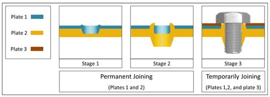
Figure 1.
Schematic of the friction drill joining potential for thin sheets joining.
As shown in Figure 2, the friction drill joining process is a modified (extended) version of the friction drilling process, where a rotational conical tool drills dissimilar sheets, AISI304 and AL6061 in this work, and performs a solid-state joining. The drilling tool penetrates the top sheet and then the bottom sheet, simultaneously generating frictional heat, softening the sheets, and forming a joint, by stirring the plasticized material of the adjacent sheets materials in the shared weld zone.
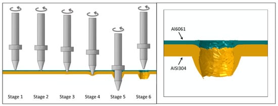
Figure 2.
Process stages involved in the friction drill joining process.
The joining approach for friction drilling, namely flow drill screwing, was considered for the first time by AK Freis [3]. In the method of flow drill screwing, the tool plays a screw role: drilling, bush-forming, threading, and, finally, seated into formed sheets. This technology is also discussed by some other researchers [24,26,27]. The effects of the fastener design, spindle speed, and fastener force on joint strength for the joining of Al5052 sheets are studied by Skovron et al. [26]. They find that fastener force has a great effect on the deflection of the top and bottom sheets. After that, the effect of thermal assistance on the joint strength under the flow drill screwing process is studied by Skovron et al. [28]. In that work, friction drill screwing is applied for the joining of Al6063-T5A. The obtained results show that preheating the sheets significantly reduces the process cycle time and installation torque; however, it does not have any great effect on the heat-affected zone. The shear test also confirms the effect of preheating on improving formed-bush quality. Later, friction drill screwing is applied for the joining of dissimilar materials, austenitic stainless steel and an aluminum alloy, by Urbikain et al. [24]. The effect of spindle speed and feed rate on joint strength are studied and the optimum parameters found. To analyze joint strength, shear tests and corrosion tests are conducted. The corrosion test helps to investigate the sheet gap space. Other experimental analysis, on the joining of the aluminum–magnesium alloy AA5182-O and dual-phase steel DP600 using a friction drill screwing process, is conducted by Aslan et al. [22].
Until now, there is no study regarding the usage of friction drilling for the joining of dissimilar materials. Note that, as mentioned earlier, the process of friction drill screwing, which was used by some researchers, differs from friction drill joining. Moreover, a comprehensive study on the joint-formation region, which contributes to the in-depth understanding of how sheets are softened, stirred, and formed, has not been yet conducted.
The main aim of this paper was to propose a novel joining technique for joining similar and dissimilar materials, namely friction drill joining, and to develop a thermo-mechanical finite element model for analyzing this process. To this end, friction drill joining of dissimilar sheets AISI304 and Al6061 was studied, both experimentally and numerically. An improved technique, which leads to improved joint strength and formed-bush quality, is also proposed and investigated. In the following, the required thrust force for piercing, stirring, and forming sheets during the process, from the initial contact between the tool and top workpiece to tool retraction from the formed bush, was studied step by step. The materials stirring, and flow materials in the stirred zone, for both the normal condition and improved condition were analyzed and compared. It helps to provide useful knowledge about the mechanism of the friction drill joining process, including how the softened materials flow and stir, and how the joint is formed.
Finally, the thermal stress, plastic strain, frictional heat generation from the start to the end of the process, and the residual stress after process completion and cooling phase were analyzed, using the finite element methodology. The numerical study strongly provides more in-depth knowledge about the process, and contributes to the understanding of how sheets are softened, stirred, and formed, and how the joint is generated. The findings are expected to contribute to providing knowledge about the process of friction drill joining, especially for the joining of dissimilar materials and cross-section tubes, where the problem of fusion and bonding between dissimilar materials is critical and persists.
2. Methodology of Work
2.1. Experimental Setup
Regarding the main aim of this work, the chosen workpiece materials were AISI304 and Al6061. Since the mainline of this research was to propose a joining approach for the friction drilling process, the effect of input variables, spindle speed, and feed rate on joint strength was studied. In addition, the required thrust force and material formation in the stir zone was characterized. As shown in Figure 3, the basic pieces of equipment needed for experimental work are a drilling machine, workpieces, and a drilling tool. In this work, a radial drilling machine (GR-412) was used for the friction drill joining of AISI304 and Al6061, with a tungsten carbide tool.
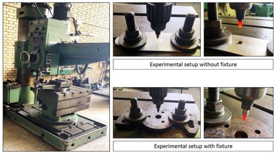
Figure 3.
Experimental setup for the friction drill joining process.
The tool geometry of the used drilling tool was a shank region of 35 mm, a shoulder region of 5 mm, a cylindrical region of 10 mm, a conical region of 9 mm, a center region of 1 mm, shank diameter of 8 mm, shoulder diameter of 14 mm, center angle of 90°, and conical angle of 37° [21,29]. The key dimensions and geometry of the tool are shown in Figure 4. Moreover, to reduce tool degradation, the tool was made of tungsten carbide in a cobalt matrix, with AlCrN coating [18,30].
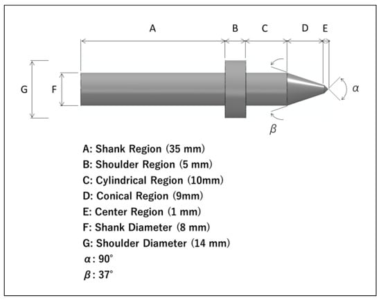
Figure 4.
Key dimensions of the tool.
These tests were performed on sheets of AISI304 with 3 mm thickness, and Al6061 with 1 mm thickness; the chemical properties are listed in Table 1. To determine the effects of spindle speed and feed rate on joint strength, a tensile-shear strength test was conducted and the results are discussed. Moreover, to analyze the efficiency of the proposed technique for improving joint quality, a tensile-shear strength test was conducted for both normal and improved conditions of friction drill joining, and then compared. To characterize the stirring and formation of sheet metals, energy-dispersive spectroscopy analysis was also conducted in the friction stir zone. Notably, material formation and the hardness of heat-affected normal condition and improved condition friction drill joining was also carried out and compared.

Table 1.
Chemical composition of AISI304 and AL6061 (wt.%) [21,31,32].
The setup of the fixture and dynamometer on the CNC machine is shown in Figure 5. As can be seen, the dynamometer was fixed on the CNC machine table, and the fixture clamped. The friction drill joining forces was recorded by dynamometer model KISTLER 9443B. Then, the collected data were imported into the data acquisition system. It should be mentioned that the CNC machine table was just used for dynamometer installation, in order to collect required trust force results.
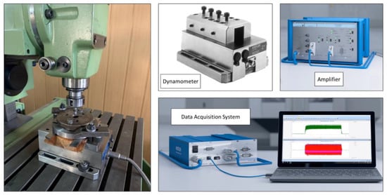
Figure 5.
Dynamometer setup for thrust force measurement.
The schematics of the normal and improvement conditions are also shown in Figure 6. The term “normal condition” refers to the case in which the fixture played a locator role for bushing joint formation. Under the normal condition, the tool penetrated the bushing until the initial contact between the tool shoulder and back-extruded materials. The term “improvement condition” refers to the case in which the fixture was modified and load clamping was sufficiently improved. In comparison with the case of the normal condition, in the case of the improvement condition, the tool entered further, until the compressing of back-extruded materials.
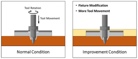
Figure 6.
Schematic of friction drill joining process under normal and improvement conditions.
In this work, in order to design the experiments (DOE), a full factorial method was applied. Regarding the findings of Ku et al. and Dehghan et al. in works on the friction drilling process [7,33], the design of experiments for this study were as follows: the spindle speed levels were 2000, 2500, and 3000 rpm, and the feed rate levels were 80, 100, and 120 mm/min.
The important concern in joining processes is joint strength [26]. In this regard, to analyze the mechanical strength of the formed joint, a tensile-shear strength test was performed [26,28,34,35]. As shown in Figure 7, the upper sheet is clamped, and a quasi-static downward displacement load applied to the lower sheet. This test was conducted with a Hounsfield H50KS test system, at a constant displacement rate of 10 mm/min, until the formed joint separated.
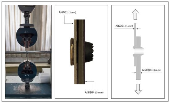
Figure 7.
Experimental and schematic illustration of the tensile-shear strength test.
To explore the hardness of the drilled hole and material stirring through the formed-joint region, the hardness of the heat-affected zone was measured. To observe the material stirring and joint formation, an optical microscope and scanning electron microscope (Philips XL30 TMP, F.E.I. Company, Hillsboro, OR, USA. made in Eindhoven, The Netherlands) were also used. At first, the workpiece was cut using a CNC wire-cut machine. Then, to measure the hardness and observe the materials stirring and joint formation, the surface of the specimens was polished. Hence, girt-sized SiC papers (320, 600, 800, 1200, and 2400) initially sanded the specimens. Afterwards, the sanded samples were polished with alumina powder. The polished specimens were prepared, and observed with an optical microscope and scanning electron microscope. After that, the hardness of the specimens (AL6061 with 1 mm thickness, and AISI304 with 3 mm thickness) was tested by a macro-hardness tester (Otto Wolpert-Werke GMBH model, LudwigshafenRhein, Germany) under an applied load of 5 kg, to measure the Vickers hardness of the adjacent area near the drilled hole. The measurements were performed according to the ISO 6507–1 standard [36].
2.2. Development of FEM Simulation Modelling
Finite element analysis is a powerful technique for simulating frictional heat generation and thermal stress to analyze complex contact problems, such as friction welding, friction drilling, friction stir forming, and friction drill joining [23,37,38,39]. In this study, the ABAQUS software with the DYNAMIC/EXPLICIT method was applied for thermo-mechanical modelling of the friction drill joining process. To analyze complex contact problems, the EXPLICIT method is recommended [40]. Since a critical concern in finite element modelling of complex contact problems is difficult convergence, the adaptive mesh technique of the arbitrary Lagrangian–Eulerian method and element deletion were applied in this case. Moreover, mesh dependency analysis was conducted, and the mesh size optimized. The sheet metals AISI304 and Al6061 were modelled in a circular shape, 25 mm radius, and 3 mm and 1 mm thickness, respectively, with 527,032 nodes, 504,000 linear hexahedral elements of type 8-node thermally coupled brick, tri-linear displacement and temperature, and reduced integration; hourglass control C3D8RT was finer at the centre of the workpiece. The element size was 0.1 * 1 mm on the whole body, and 0.1 * 0.1 mm on the centre of the workpiece, where the drilling tool penetrated the material. The number of elements through the workpiece thickness was also 30.
To simulate the material behaviour, the plastic strain-rate-dependent material law, and the frictional heat generation based on the elastic–plastic Johnson–Cook material model, were applied. The meshed assembly is also presented in Figure 8.
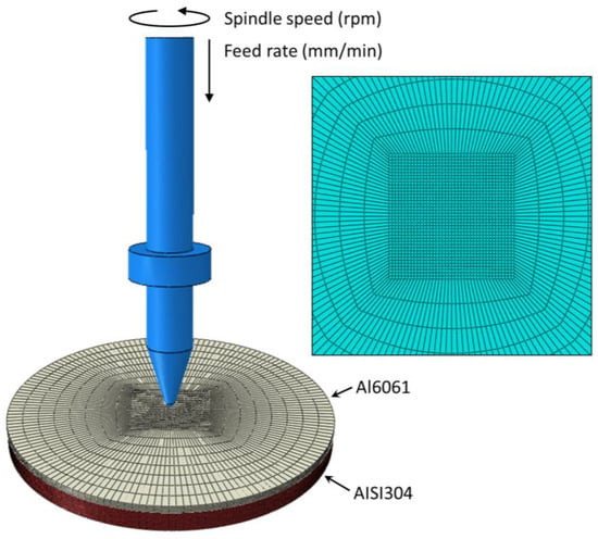
Figure 8.
Mesh generated in developed thermo-mechanical finite element model.
To improve the softened-material flow, bushing formation, and joining quality, a specific fixture was also designed and fabricated in this work. The designed fixture may cause better load clamping and formed joints. Figure 9 indicates the assembly of the finite element model for the normal and improvement conditions. As observed, under the normal condition, the sheets are just clamped from the bottom; however, they are clamped from both the bottom and top under the improvement condition.
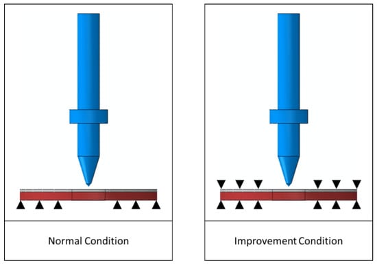
Figure 9.
Numerical setup for finite element analysis.
To simulate the friction drill joining process, the elastic–plastic Johnson–Cook material model [41], expressed as the following Equation (1), was used:
where is the yield stress, is the effective plastic strain, is the effective plastic strain rate, and is the normalizing strain rate (typically, ) [42]. , and are material constants. is the ambient temperature, which is 25 °C in this case. This material model is a type of von Mises plasticity model, with analytical forms of the hardening law and rate dependence. Due to the tool movement into the workpiece, a failure criterion was required to characterize the material properties degradation.
In the present scheme, the Johnson–Cook failure model, based on the plastic strain, was applied. In this model, if parameter reaches the value of 1, failure occurs:
To fracture fε, the equivalent strain is defined by [43]:
where to are material constants, which can be determined from experiments, and is the hydrostatic pressure, i.e., the third of the trace of the Cauchy stress tensor.
According to Equation (2), when the damage variable reaches 1, the material stiffness is fully degraded, then the relevant elements are deleted, and the crack generated.
The mechanical and thermal properties, material properties, and Johnson–Cook parameters used for the simulation of friction drill joining of AISI304 and Al6061 are presented in Table 2, Table 3 and Table 4.

Table 2.
Temperature-dependent Young’s modulus, specific heat, Poisson ratio, thermal conductivity, expansion coefficient, and mass density for AISI304 [17].

Table 3.
Temperature-dependent Young’s modulus, specific heat, Poisson ratio, thermal conductivity, expansion coefficient, and mass density for AL6061 [43].

Table 4.
Johnson–Cook material damage properties for AISI304 and AL6061 [17,32].
3. Results and Discussion
3.1. Experimental Analysis
The experimental analysis starts with a comparison between the required thrust force for the friction drill joining of AISI304 with 3 mm thickness and Al6061 with 1 mm thickness, and the necessary thrust force for friction drilling of AISI304 with 3 mm thickness. As presented in Figure 10, the trends of the graph are almost similar. An upward trend of the required thrust force starts from the initial point of cycle time, and continues until the sheet material becomes soft. The required thrust force then reduces, until the central region of the tool fully penetrates the workpiece. After this step, the uptrend begins, which is because the contact region of the tool with the workpiece material changes from the center to the conical area. At this time, the bush formation begins. The end of the bush formation is where the graph shows a downward trend. During this process time, the cylindrical region of the tool is in contact with the hole wall of the formed bush. The difference between the two lines of the graph given in Figure 10 shows the maximum and the minimum points of the required thrust force. As is observed, the first maximum point of the friction drill joining graph is 3725 N, and its value for the friction drilling graph is 3535 N. It shows that the added workpiece, Al6061 with 1 mm thickness, increases the required thrust force by about 5%. In other words, increasing the sheet layers does not increase the required thrust force significantly, which is considered a unique feature for the multi-layer joining performed using this technology. When materials are softened, the required thrust force gradually reduces. As observed in Figure 10, the friction drilling line graph reduces to about 2550 N, and the friction drill joining line graph drops to about 1400 N. Since the initial contact of the tool with the workpiece is with the Al6061 sheet, in the friction drill joining process, the Al6061 sheet softens and forms into AISI304 sheet, and transfers its frictional heat generation into the AISI304 sheet. This phenomenon works similarly to preheating for the AISI304 sheet. Therefore, the tool penetrates AISI304 more easily than Al6061. After this step, as mentioned above, the second uptrend is related to the required thrust force for changing the contact area of the tool from the center region to the conical region, and the bushing formation. As can be seen, the upward trend of the friction drill joining graph is more dramatic than the friction drilling graph. The reason for this phenomenon is the temperature reduction during the process. In other words, temperature reduction increases the thrust force needed for the penetration of the tool into the workpiece.
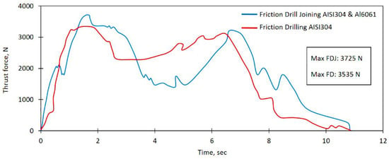
Figure 10.
Comparison of required thrust force for friction drilling and friction drill joining process.
In the following, the effect of spindle speed and feed rate on the mechanical strength of the formed joint under the normal condition is studied. It helps develop understanding of how process parameters affect joint strength. To improve the joint strength and quality of the formed bush, an improvement methodology is provided, and compared with the optimum formed bush under the normal condition. In the applied improvement technique, the fixture is modified, and the pressure from the tool on sheets becomes more efficient.
The effect of spindle speed and feed rate on the strength of formed-joint and tool performance is displayed in Figure 11a–c. As is observed, the maximum joint strength is obtained under the spindle speed 2500 rpm and feed rate 100 mm/min, where the tensile-shear strength test fails at 4850 N load. In other words, more efficient frictional heat generation, for better softening and stirring of sheets materials, which leads to a more adequate joining of the sheets, is provided by this combination of process parameters.
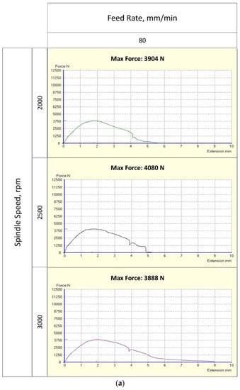
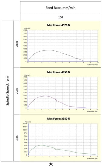
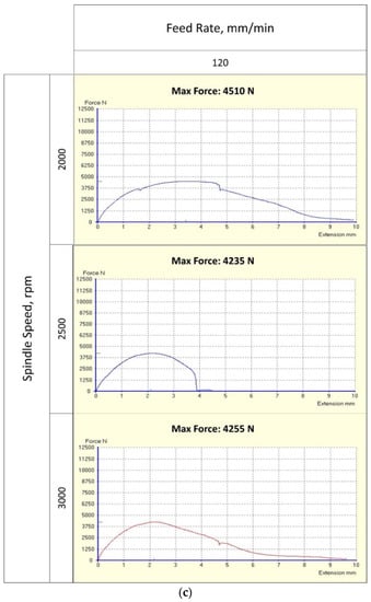
Figure 11.
Tensile-shear strength test on formed joints under the normal condition with different spindle speeds and feed rates. (a) Tensile-shear test with feed rate 80 mm/min and spindle speeds 2000, 2500, and 3000 rpm. (b) Tensile-shear test with feed rate 100 mm/min and spindle speeds 2000, 2500, and 3000 rpm. (c) Tensile-shear test with feed rate 100 mm/min and spindle speeds 2000, 2500, and 3000 rpm.
Although friction drill joining has great potential for joining dissimilar multi-layer sheets, the gaps between layers, caused by flow material, are a critical challenge for the applicability of this technology in industry [24,26]. In other words, this issue allows infiltration of humidity, causes crevice corrosion, and reduces joint strength [24]. Therefore, the necessity of an improvement methodology, to reduce the sheet gap and improve the quality of formed-joint, exists.
Figure 12 presents the corresponding load versus displacement line graph. The line graph shows that the formed-joint strength under the normal condition, with an optimum combination of input variables (spindle speed 2500 rpm and feed rate 100 mm/min), fails at 4850 N without any fixture and additional pressure. However, the formed-joint strength under the improvement condition improves by about 10%, and the formed-joint fails at 5335 N, with the fixture and additional pressure on the top sheet.
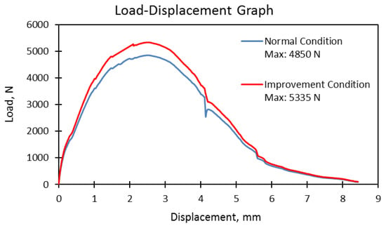
Figure 12.
Comparison of normal and improvement conditions by the corresponding load versus displacement.
The material formation of the workpieces and how the Al6061 sheet (the top sheet) stirs into the AISI304 sheet (the bottom sheet) is represented in Figure 13. The cross-sectional view of the formed-joint under the normal and improvement conditions is illustrated in Figure 13. The improvement condition causes the sheet gap to reduce significantly, from 1.86 mm to 0.54 mm. It means that the extra pressure on the top sheet not only prevents softened materials from reaching the sheet gap, but also causes stirring of the top sheet with the bottom sheet. As observed in the SEM picture of the improvement condition, the bottom sheet extrudes to the top surface of the top sheet, and a mechanical joining between the two sheets forms, which helps improve the joint strength and quality of the formed bush.
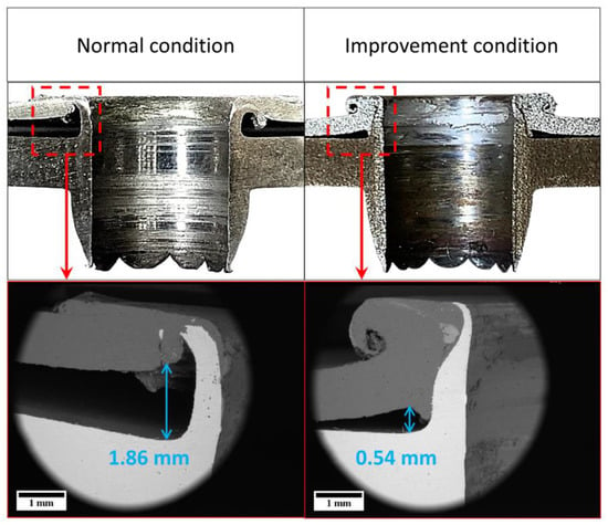
Figure 13.
Cross-section and close-up views of back-extruded materials zones for friction-drilled joints under normal and improvement conditions.
To determine the effect of heat generation during the process on hardness, the hardness of the heat-affected zone on the adjacent area near the drilled-hole wall is measured, as represented in Figure 14. Moreover, to investigate the effect of the improvement condition on bushing formation and joint strength, the hardness results of the normal and improvement conditions are compared. The results demonstrate that the hardness near the hole edge is higher than the tested points away from the hole edge.
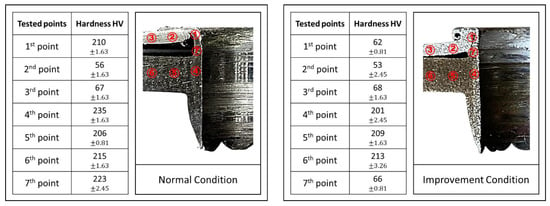
Figure 14.
The hardness of seven tested points.
The authors in [31] discover that hardness decreases by moving away from the hole edge, due to less heat generation and slow temperature reduction. This fact causes coarser grain size [31]. Thus, here, it is claimed that by moving away from the hole edge, the grain size becomes coarser.
As revealed in Figure 14, a comparison between the hardness results of the normal and improvement conditions shows that Al6061 and AISI304 sheets are better stirred, and material mixing more effective, under the improvement condition than under the normal condition. The hardness of the 1st and 7th points under the improvement condition indicates that the bottom sheet (Al6061) stirs, extrudes, and mixes with the top sheet (AISI304) more sufficiently and effectively than under the normal condition. Furthermore, the AISI304 sheet is back-extruded to the top surface of the Al6061 sheet, and forms a more efficient mechanical joining under the improvement condition than under the normal condition.
Figure 15 shows the SEM picture of the red zone from the cross-sectional view of the formed joint. As is observed, two areas in the red zone for energy-dispersive X-ray analysis are selected and compared under normal and improvement conditions. The high amount of the Al element (normal condition: 94.1% and improvement condition: 93.52%) in selected area 1 confirms that this selected area is related to workpiece material Al6061. On the other hand, the amount of the Al, Fe, and Ni elements in selected area 2 for the normal condition (33.99%, 48.09%, and 5.91%, respectively) shows that sheet AISI304 stirs into sheet Al6061, and the joint forms. Moreover, the amount of the Al, Fe, and Ni elements in selected area 2 for the improvement condition (0.07%, 73.66%, and 8.24%, respectively) confirms that sheet AISI304 properly stirs into sheet Al6061, and the joint formation is more sufficient than the joint formation in the normal condition.
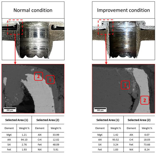
Figure 15.
Cross-section and close-up views, and energy-dispersive X-ray analysis of back-extruded materials zones for friction-drilled joints, under normal and improvement conditions.
It is worth mentioning that the SEM results of Figure 15 prove that the bottom sheet, AISI304, is sufficiently back-extruded to the top surface of the Al6061 sheet under the improvement condition, and it causes a mechanical joining between AISI304 and Al6061 back-extruded materials.
Figure 16 presents SEM pictures of the edge zone and energy-dispersive X-ray analysis for two selected areas. The obtained results of the energy-dispersive X-ray analysis for normal conditions shows the weight percentages of the Al and Fe elements in selected area 1 as 95.75% and 3.46%, respectively; these amounts change to 66.5% and 24.24%, respectively. The change in the Al weight percentage from the top area (95.75%) to the bottom area (66.5%) implies that the sheet material gradually changes from Al6061 to AISI304. On the other hand, the change in the Fe weight percentage from the top area (3.46%) to the bottom area (24.24%) displays the material changing from the top sheet Al6061 to the bottom sheet AISI304. However, the amount of the Al element in selected area 2 is 66.5%, and shows the good softening, extruding, and forming of Al6061 to AISI304.
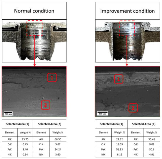
Figure 16.
Cross-section and close-up views, and energy-dispersive X-ray analysis of edge zones for friction drilled joints, under normal and improvement conditions.
As observed from the energy-dispersive X-ray analysis of the improvement condition, the weight percentage of the elements Al and Fe change from 29.32% and 51.93% in selected area 1, to 55.41% and 30.6% in selected area 2, respectively. Contrary to the weight percentage of the Al element in two selected areas of the normal condition, which reduces from the top region of the bush to the bottom region, it increases from 29.32% to 55.41% under the improvement condition. It can be stated that the bottom sheet (AISI304) is back-extruded more correctly to the top sheet (Al6061) under the improvement condition than it is under the normal condition, and it causes a reduction in the Al element weight percentage at the top area to 29.32%. In sequence, due to the adequate stirring of Al6061 to AISI304, the element increases to 55.41% in the bottom area.
Moreover, the reduction of the Fe element weight percentage from 51.93% in the top area to 30.6% in the bottom area confirms the sufficient stirring of the top and bottom sheets, and the formation of a good joint under the improvement condition.
Figure 17 shows the SEM pictures from the formed joint and energy-dispersive X-ray analysis conducted for the selected areas of the center region of formed joints under the normal and improvement conditions. As a comparison, the SEM results show that the surface quality of bush formed under the normal condition is poorer than it is under the improvement condition. Several cracks and severe damage in the center region of the formed bush are clearly observed. Conversely, the surface quality of the bush formed under the improvement condition significantly improves. Indeed, the efficient clamping and fixing of sheets significantly leads to improved material stirring, joint strength, and quality of the bush formed.
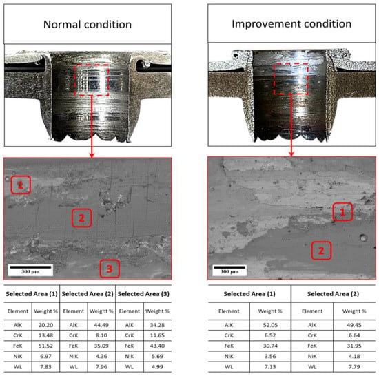
Figure 17.
Cross-section and close-up views, and energy-dispersive X-ray analysis of center zones for friction drilled joints, under normal and improvement conditions.
The energy-dispersive X-ray analysis of selected areas for the formed bush is also presented in Figure 17. The weight percentage of the Al element in three selected areas under the normal condition is top zone, 20.20%; center zone, 44.49%; and bottom zone, 34.28%, respectively. The Fe element is also scanned in three areas: top zone, 51.52%; center zone, 35.09%; and bottom zone, 43.40%. Regarding the energy-dispersive X-ray, it can be stated that the stirring of the Al6061 sheet into AISI304 is not uniform, and is similar to a strip. The reason for the vertical cracks in the center zone of the formed bush under the normal condition is the stirring of the sheets in strip form. On the other hand, the weight percentages of the Al and Fe elements for two selected areas under the improvement condition are top zone, 52.05%; and bottom zone, 49.45% for the Al element, and top zone, 30.74%; and bottom zone, 31.95% for the Fe element. The small difference between the amount of Al and Fe elements, which are scanned on the top and bottom zones of the center region of the formed bush, implies the uniformity of sheet stirring, and confirms the high-quality of the formed joint.
In addition, the presence of the W element on the formed bush under both normal and improvement conditions is strong evidence of tool degradation and abrasive wear, which removes material from the drilling tool and transfers it to the contact surface of the workpiece.
Figure 18 displays SEM mapping of the center region of the formed joint under the normal condition. The “K” in the SEM mapping result indicates the ratio of characteristic intensities measured on the specimen and standard. As discussed above, the vertical cracks observed in the SEM picture confirm the poor quality of the formed joint under the normal condition. In sequence, the weight percentage of the Al element becomes 49%, which is the maximum presence element in the scanned area. The SEM mapping of the Al element clearly shows the stirring of this element on the formed bush surface in the strip form. The SEM mapping of the Fe element shows that it is also stirred in the strip form, and it proves the insufficient stirring of sheets and poor quality of formed joint. The presence of the O element confirms the oxidization of the formed bush. Furthermore, as mentioned above, the presence of the W element shows the abrasive wear on the tool, material removal from it, and the transfer of the W element from the tool to the formed bush.
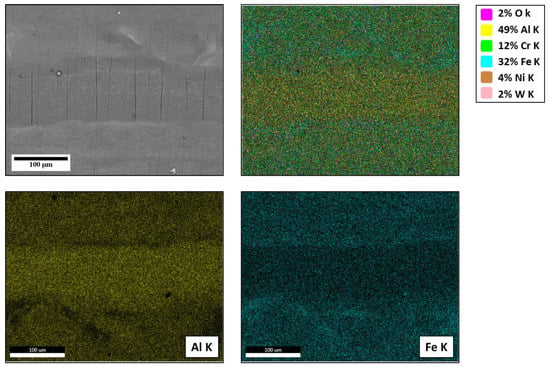
Figure 18.
Scanning electron microscope (SEM) mapping of the center zone of friction drilled joint under normal condition.
The SEM mapping of the center region of the formed joint under the improvement condition is presented in Figure 19. As seen from SEM mapping of the Al element, this element is distributed throughout the formed bush. It is also observed that the Al element distribution at the bottom zone of the SEM picture is denser than in the top zone. The presence of the Fe element, which is at the bottom of the workpiece sheet, is denser in the upper area. The distribution of the Al and Fe elements confirms the proper sheet stirring and high-quality of the formed joint. As stated and discussed above, the presence of the O element shows oxidization on the formed bush, and the W element proves abrasive tool wear, and material transferring from tool to workpiece.
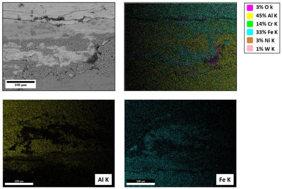
Figure 19.
Scanning electron microscope (SEM) mapping of the center zone of friction drilled joint under improvement condition.
Figure 20 displays optical images of the formed-joint region under the improvement condition. Figure 20a shows the optical view of the formed-joint region under the normal condition. The materials softening, and the back-extruding of the softened materials, which leads to the mechanical joining of the AISI304 and AL6061 sheets, are presented in zone (a). Figure 20 also reveals the high-magnified views of the formed-joint region where the back-extruded materials are stirred and make a mechanical joining, marked by zone (b) and zone (c). It can be stated that the interaction line of the merged materials is clearly observed in zones (b) and (c). From Figure 20d, the stirring of AISI304 and AL6061 in the bushing region is clearly observed. In other words, the top sheet, AL6061, forms on the AISI304 along the formed-bush region, and helps make the formed joint more effective.
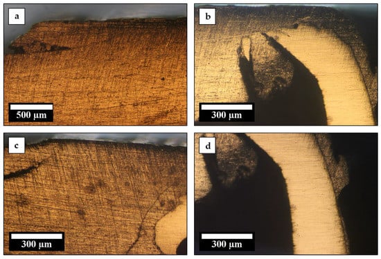
Figure 20.
Optical image of the formed-joint zone under normal condition. (a) back-extruded of the softened materials. (b) formed-joint region. (c) high-magnified view of formed-joint region. (d) materials stirring in bushing region.
In sequence, Figure 21 presents optical images of the formed-joint area under the improvement condition. The high-magnified views of the formed-joint region, i.e., boxes (a), (b), and (c), show that joint formation quality under the improvement condition is more effective than under normal condition. Moreover, the optical image of the box (d) confirms the great effect of friction drill joining under the improvement condition in improving joint formation quality. It can be stated that Figure 21d shows that the sheet gap is significantly reduced under the improvement condition, and it helps improve the joint strength and quality of the formed bush.
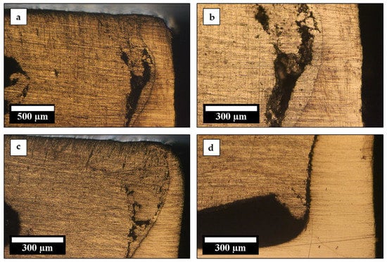
Figure 21.
Optical image of the formed-joint zone under improvement condition. (a) back-extruded of the softened materials. (b) formed-joint region. (c) high-magnified view of formed-joint region. (d) materials stirring in bushing region.
3.2. Numerical Analysis
To study the strength of the relationship between the experimental work and the finite element model, a comparative study is needed. In this study, the finite element model is evaluated and verified with experimental work, using the required thrust force for the friction drill joining process.
As shown in Figure 22, the experimental work is compared with the numerical model that predicts the thrust force in friction drill joining of AISI304 and Al6061. The line graphs show that the numerical model and the experimental work are highly correlated. The difference between the R-squared values is about 0.0464, which is negligible. This confirms a strong agreement between the numerical model and experimental work.
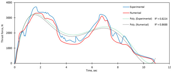
Figure 22.
Prediction and comparison of required thrust force for experimental work and numerical model.
In the following, the thermal stress, plastic strain, and frictional heat generation during the joining process are analyzed.
Friction drill joining is a thermal process in which heat generates from friction between the tool and the workpiece. Indeed, frictional heat generation softens the workpiece first; consequently, the bushing is formed. As seen in Figure 23, the initial contact between the tool and the workpiece in the top sheet happens at stage 1. The maximum thermal stress point at the first stage is 270,000,000 Pa. Bypassing time, the tool nearly penetrates the top sheet at stage 2. In this stage, the thermal stress increases, and reaches 680,000,000 Pa. It is worth mentioning that the thermal stress is distributed in the top and bottom sheets. In stage 3, where the tool pierces the top sheet and begins to penetrate the bottom sheet, the thermal stress distribution gradually decreases over the top sheet, while it increases in the bottom sheet. The maximum thermal stress at the third stage is 1,700,000,000 Pa. In the next stage, stage 4, the top sheet is almost stirred into the bottom sheet, and bushing formation begins in the bottom sheet. The maximum thermal stress, 2,000,000,000 Pa, occurs on the bottom sheet at this stage, where the bottom sheet encompasses the conical region of the tool. Finally, the joining of sheets and bushing formation process is completed at the fifth stage. At the end of the process, the thermal stress gradually expands throughout the sheets. As observed from stage 5, the important point is the big difference in thermal stress between the top and bottom sheets at the end of the joining process, which may the key point for solving the problem of an existing gap between the top and bottom sheets.

Figure 23.
Equivalent thermal stress, or Von Mises stress, for friction drill joining of AISI304/Al6061, at different stages.
Figure 24 presents the plastic strain distribution on the formed-joint zone, from the start to the finish of the process. It should be noted that, at first, due to the large deformation in this process, adaptive meshing and element deletion techniques by plastic strain criterion, equivalent to the plastic strain value of 2.2, are necessary to maintain the mesh quality. From initial contact between the tool and top sheet, a plastic strain with the maximum value of 0.9 is observed in stage 1. Bypassing time, tool movement, and material formation in stages 2 and 3, the plastic strain increases and expands inside and adjacent to the effective zone. The maximum plastic strain occurs at stage 4, where the conical region of the tool is in contact with the hole wall. Most of the material stirring and joining is performed at this cycle time. Moreover, the bushing formation begins at this stage. Finally, the contact interface between the sheets and the tool changes from the conical region to the cylindrical region, and the joining process and bushing formation are simultaneously completed at stage 5.

Figure 24.
Plastic strain for friction drill joining of AISI304/Al6061, at different stages.
The interaction between tool and workpiece leads to frictional heat generation, materials softening, stirring, and joining, and bushing formation. Figure 25 presents the friction heat generation from the initial contact between the tool and top sheet to the end of the process during these 5 stages. The process starts with the initial contact between the center region of the tool and the top sheet at a room temperature of 25 °C. Bypassing time, the tool travels into the sheet and the temperature increases to 91.6 °C. In the third stage, where the tool pierces into the top sheet and penetration into the bottom sheet starts, the frictional heat generation reaches 283.6 °C. In the next stage, stage 4, where the top sheet is mostly stirred into the bottom sheet, and the bushing forms, the frictional heat generation experiences an extreme rise, to the peak point of 1365.8 °C. Stage 5 begins with more tool travelling. In this stage, the material stirring and joining, and bushing formation, are completed, and the temperature reduces gradually. It is worth stating that the significant point of the temperature field from Figure 25 is the severe temperature gradient between the top and bottom sheets in the bushing formation and joining region. This concern may cause shrinkage in the top sheet when the bottom sheet material softens and extrudes down. This issue can be the main reason for the separation of sheets, which is an important problem in the friction drill joining technology.

Figure 25.
Frictional heat generation for friction drill joining of AISI304/Al6061, at different stages.
To compare the experimental work and numerical model, the cross-sectional view of experimental and numerical results is revealed in Figure 26. As is observed, the experimental and numerical findings are mostly similar, except in back-extruding materials, which are caused by the effects of finite element simulation issues, such as an adaptive meshing technique, an element deletion technique, mesh size, etc. The numerical results of thermal stress, plastic strain, and frictional heat generation bring a better understanding of material stirring and how sheets are joined. Moreover, as discussed above, it is clear that the high-temperature gradient between the top and bottom sheets, which causes a sharp difference in thermal stress, plays a significant role in the separation of sheets. This issue results in moisture and salt accumulation, leading to crevice corrosion and pitting, and dramatically reduces the service life of potential products in adverse conditions, and limits the field of product application. To overcome this problem, it is suggested that preheating and thermal assistance are applied, which contribute to a reduction in the temperature gradient between the top and bottom sheets.
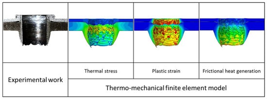
Figure 26.
Comparison of experimental friction-drilled joint versus numerical predicted thermal stress, plastic strain, and frictional heat generation.
Figure 27 presents the nodal displacement vectors, flow sheets material, and how materials are stirred and joined. As observed from stage 1, where the center region of the tool contacts the top sheet, the surrounding area of this region desires to extrude in the back direction. Efficient clamping of the upper surface of the top sheet, proposed in this work as an improvement condition, significantly prevents this issue. The nodal displacement vectors show the time when the tool almost pierces the top sheet and the initial contact between the tool and bottom sheet begins (stages 2 and 3). Due to the top sheet shrinkage, the top sheet material significantly extrudes to the back. However, the directions of the vectors in stage 3, which are down, left, and right, clearly show the effect of efficient clamping of sheets in reducing the sheet separation, and improving the joint strength. Next, in stages 4 and 5, where the temperature of the bottom sheet material increases significantly and the material softens, the temperature of the top sheet drops. The severe temperature gradient between the top and bottom sheets on the adjacent area of the drilled-hole causes inadequate joining in this area, and the gap area between them is generated. The direction of the nodal vectors in stages 4 and 5 proves the theory of sheet separation generation. Therefore, although the sheet clamping significantly improves the joint quality, to reduce the severe temperature gradient between the top and bottom sheets, it is suggested to apply thermal assistance, or preheating. The direction of the nodal displacement vectors confirms that thermal assistance, or preheating, effectively helps to reduce the sheet gap.
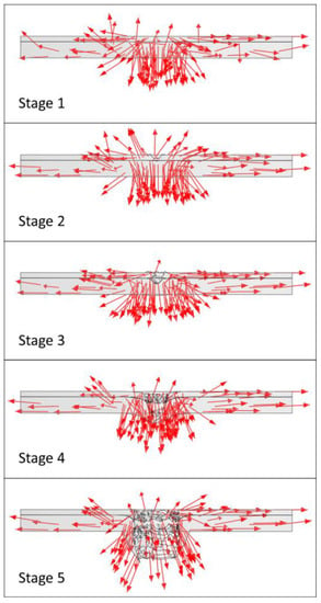
Figure 27.
Numerical results of nodal vectors of elements displacement for friction drilled joint at different stages.
Figure 28 shows the residual stress distribution on the formed bush after the cooling phase. Residual stress is crucial in joining dissimilar materials, as it can drastically reduce fatigue life. The main sources of residual stress are (a) the difference between the thermal expansion coefficients of stainless steel and the aluminum alloy, and (b) aluminum alloy displacement through plastic flow. As indicated in Figure 28, the strip of maximum residual stress exists where the maximum contact between the tool and materials occurs. The maximum residual stress is generated in the materials joining interface, where the maximum element distortion and material stirring occurs Another reason for high residual stress in this region can be the different thermal expansion coefficients between stainless steel and the aluminum alloy. Moreover, three paths on the formed bush are drawn, and the residual stress along them is measured. The residual stress plot in path 1 shows that the residual stress in corners is higher than in the center.
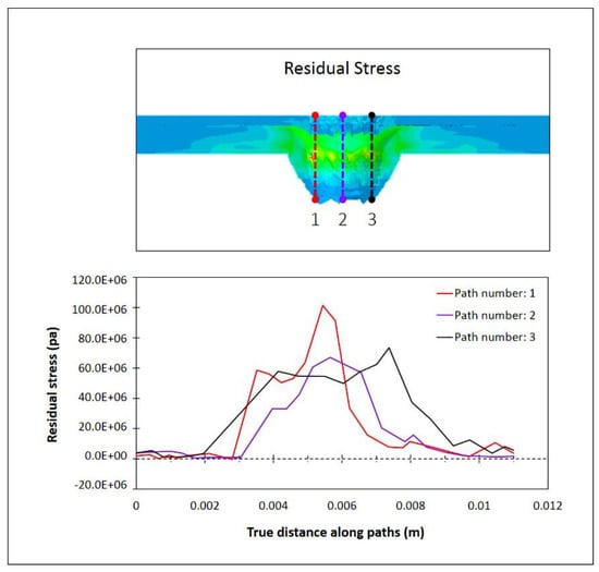
Figure 28.
Residual stress distribution throughout the formed-bush region, and along the three paths.
Finally, to show the effect of efficient clamping on sheet gap reduction and joint quality improvement, Figure 29 compares the drilled joint quality under the normal and improvement conditions, using finite element analysis. As is observed, the numerical results are strongly supported, and prove that the experimental results lead to the better stirring of the materials, and improve the joint quality.
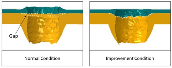
Figure 29.
Numerical prediction and comparison between friction-drilled joints under normal and improvement conditions.
4. Conclusions
In this study, a new approach for the friction drilling process, namely, friction drill joining for the joining of multi-layered dissimilar sheets, was proposed. This joining technique is a solid-state process, for the joining of similar and dissimilar sheet material. The significance of this joining method is the fact that it is one-sided technology, has better accessibility, and the ability to join round cross-section tubes, which is quite complex. Moreover, the unique plus point of this technique, compared to other joining methods, is the combination of permanent and temporary joining. In other words, after the permanent joining of sheets using this technique, it is possible to add more sheets to the joint using temporary joining.
To understand the process and analyze the softening, stirring, and joining of sheets this study focused on experimental and numerical analysis of friction drill joining of the dissimilar materials AISI304/Al6061. Moreover, to improve joint strength and formed-bush quality, an improvement method was discussed, both experimentally and numerically. It is proven that the developed thermo-mechanical finite element model is significantly supported by the experimental results. The developed FE model in this study greatly helps to understand the sheet separation concern, and how this issue can be solved.
The most salient and significant findings of this paper are summarized and listed as follows;
- The experimental results of thrust force line graphs for the friction drilling of AISI304, with a thickness of 3 mm, and friction drill joining of AISI304 with a thickness of 3 mm and Al6061 with a thickness of 1 mm, prove that adding sheet layers does not significantly affect the required thrust force in these processes. This is one of the unique features of the friction drill joining process;
- The load-displacement graph displays that the efficient clamping and fixing of sheets contributes to improving the joint strength and formed-bush quality;
- The microscopic results and energy-dispersive spectroscopy findings show how the top sheet softens, stirs, and forms into the bottom sheet, and how the joint is generated. Moreover, the SEM pictures confirm the effect of effective clamping on improving sheet stirring and joint strength.
- The SEM pictures demonstrate that without using effective clamping, vertical cracks (resulting from insufficient material stirring) are generated. Effective clamping can eliminate the cracks and improve the joining strength;
- The numerical results of stress distribution show the maximum thermal stress is at the fourth stage, where the top sheet is stirred into the bottom sheet and bushing is formed. Moreover, huge thermal stress at stage 5, where the joining process is almost completed, occurs;
- The numerical findings of frictional heat generation strongly support the thermal stress results, and show the severe temperature gradient, which is the key point of sheet separation issue, in stages 4 and 5;
- The nodal displacement vectors from the numerical results confirm the effect of the clamping of the top and bottom sheets on preventing flow-softened material back-extruding and sheet gaps;
- The developed finite element analysis gives accurate results for residual stress distribution in the friction drill joining process, and the outcomes show that maximum residual stress exists on the formed-hole edge;
- Finally, the comparative FE results clearly show the significant effect of efficient sheet clamping in the proposed technique for reducing and eliminating the sheet gap, and improving the joint strength.
As the proposed approach of friction drilling process for joining similar and dissimilar multi-layer sheets and round cross-section tubes, which is called friction drill joining in this work, has unique features and excellent advantages, different studies can be developed for different materials. Moreover, further studies on thermo-mechanical model improvement, the effect of preheating and thermal assistance, and simulation optimization of this process are highly recommended for future studies.
Author Contributions
Conceptualization, S.D. and R.A.; methodology, S.D., R.A., M.L.M. and E.S.; formal analysis, S.D. and R.A.; investigation, S.D.; resources, S.D.; data curation, S.D., R.A., B.T.H.T.b.B. and E.S.; writing—original draft preparation, S.D.; writing—review and editing, S.D., B.T.H.T.b.B. and E.S. All authors have read and agreed to the published version of the manuscript.
Funding
This research was supported by Universiti Putra Malaysia (UPM), through Putra Grant (GP-GPB/2021/9700600).
Institutional Review Board Statement
Not applicable.
Informed Consent Statement
Not applicable.
Data Availability Statement
Data is contained within the article.
Acknowledgments
This research was funded by the Putra Grant (GP-GPB/2021/9700600) under the University Putra Malaysia (UPM).
Conflicts of Interest
The authors declare no conflict of interest.
References
- EPA EPA and NHTSA Set Standards to Reduce Greenhouse Gases and Improve Fuel Economy for Model Years 2017–2025 Cars and Light Trucks. Regul. Announc. Off. Transp. Air Qual. 2012, 1–10. Available online: https://www.nhtsa.gov/staticfiles/rulemaking/pdf/cafe/CAFE_2017-25_Fact_Sheet.pdf (accessed on 25 April 2022).
- Lazarevic, S.; Miller, S.F.; Li, J.; Carlson, B.E. Experimental analysis of friction stir forming for dissimilar material joining application. J. Manuf. Process. 2013, 15, 616–624. [Google Scholar] [CrossRef]
- Freis, A.K. Method of flow drill screwing parts. U.S. Patent 8,857,040, 14 October 2014. [Google Scholar]
- Khan, H.A.; Li, J.; Shao, C. Analyses of friction stir riveting processes: A. review. J. Manuf. Sci. Eng. 2017, 139, 100216. [Google Scholar]
- Khan, H.A.; Wang, K.; Pei, S.; Li, J.; Miller, S. Fatigue damage evolution of micro friction stir blind riveting joint through acoustic emission analysis. Materialia 2019, 5, 100216. [Google Scholar] [CrossRef]
- Wang, W.; Wang, K.; Khan, H.A.; Li, J.; Miller, S. Numerical analysis of magnesium to aluminum joints in friction stir blind riveting. Procedia Cirp 2018, 76, 94–99. [Google Scholar] [CrossRef]
- Dehghan, S.; Soury, E.; Ismail, M.I.S.B. A comparative study on machining and tool performance in friction drilling of difficult-to-machine materials AISI304, Ti-6Al-4V, Inconel718. J. Manuf. Process. 2021, 61, 128–152. [Google Scholar] [CrossRef]
- Sun, X.; Khaleel, M.A. Dynamic strength evaluations for self-piercing rivets and resistance spot welds joining similar and dissimilar metals. Int. J. Impact Eng. 2007, 34, 1668–1682. [Google Scholar] [CrossRef]
- Lazarevic, S.; Ogata, K.A.; Miller, S.F.; Kruger, G.H.; Carlson, B.E. Formation and structure of work material in the friction stir forming process. J. Manuf. Sci. Eng. 2015, 137, 1–8. [Google Scholar] [CrossRef]
- Van Belle, L.; Brandolisio, D.; Deckers, E.; Jonckheere, S.; Claeys, C.; Plumyers, B.; Desmet, W. Experimental validation of numerical structural dynamic models for metal plate joining techniques. J. Vib. Control 2017, 24, 3348–3369. [Google Scholar] [CrossRef]
- Skovron, J.D.; Ruszkiewicz, B.; Mears, L.; Abke, T.; Raymond, A.; Varma, A.; Li, Y.; Choi, H.; Zhao, X. Investigation of the cleaning and welding steps from the friction element welding process. In Proceedings of the Manufacturing Science and Engineering Conference MSEC2017, Los Angeles, CA, USA, 4–8 June 2017. [Google Scholar]
- Tamjidy, M.; Baharudin, B.T.; Paslar, S.; Matori, K.A.; Sulaiman, S.; Fadaeifard, F. Multi-objective optimization of friction stir welding process parameters of AA6061-T6 and AA7075-T6 using a biogeography based optimization algorithm. Materials 2017, 10, 533. [Google Scholar] [CrossRef]
- Springer, H.; Kostka, A.; Dos Santos, J.F.; Raabe, D. Influence of intermetallic phases and Kirkendall-porosity on the mechanical properties of joints between steel and aluminium alloys. Mater. Sci. Eng. A 2011, 528, 4630–4642. [Google Scholar] [CrossRef]
- Cao, R.; Sun, J.H.; Chen, J.H.; Wang, P.-C. Cold metal transfer joining of aluminum AA6061-T6-to-galvanized boron steel. J. Manuf. Sci. Eng. 2014, 136, 051015–051025. [Google Scholar] [CrossRef]
- Rao, Z.; Liu, J.; Wang, P.-C.; Li, Y.; Liao, S. Modeling of cold metal transfer spot welding of AA6061-T6 aluminum alloy and galvanized mild steel. J. Manuf. Sci. Eng. 2014, 136, 051001–051012. [Google Scholar] [CrossRef]
- Ogata, K.A.; Lazarevic, S.; Miller, S.F. Dissimilar material joint strength and structure for friction stir forming process. In Proceedings of the International Manufacturing Science and Engineering Conference, Detroit, MI, USA, 9–13 June 2014; p. V002T02A076. [Google Scholar]
- Dehghan, S.; Ismail, M.I.S.B.; Souri, E. A thermo-mechanical finite element simulation model to analyze bushing formation and drilling tool for friction drilling of difficult-to-machine materials. J. Manuf. Process. 2020, 57, 1004–1018. [Google Scholar] [CrossRef]
- Dehghan, S. Experimental and Numerical Investigation on Friction Drilling of Difficult-to-Machine Materials. Ph.D. Thesis, University Putra Malaysia, Seri Kembangan, Malaysia, February 2019. [Google Scholar]
- Pereira, O.; Urbikaín, G.; Rodríguez, A.; Calleja, A.; Ayesta, I. Process performance and life cycle assessment of friction drilling on dual-phase steel. J. Clean. Prod. 2019, 213, 1147–1156. [Google Scholar] [CrossRef]
- Miller, S.F.; Shih, A.J. Friction drilling: A chipless hole making process. In Proceedings of the International Conference on Manufacturing Science & Engineering (ASME), Ypsilanti, MI, USA, 8–11 October 2006. [Google Scholar]
- Dehghan, S.; Ismail, M.I.S.B.; Ariffin, M.K.A.B.M.; Baharudin, B.T.H.T.B. Friction Drilling of Difficult-to-Machine Materials: Workpiece Microstructural Alterations and Tool Wear. Metals 2019, 9, 945. [Google Scholar] [CrossRef]
- Aslan, F.; Langlois, L.; Balan, T. Experimental analysis of the flow drill screw driving process. Int. J. Adv. Manuf. Technol. 2019, 104, 2377–2388. [Google Scholar] [CrossRef]
- Liu, W.; Zhu, X.; Zhou, Q.; He, H.; Liu, J.; Xu, C.; Li, L. Modeling and simulation of the flow drill screw process of a DP590/Al6061-T6 multi-material joint used for vehicle body. Int. J. Adv. Manuf. Technol. 2020, 110, 1189–1201. [Google Scholar] [CrossRef]
- Urbikain, G.; Perez, J.M.; de Lacalle, L.N.L.; Andueza, A. Combination of friction drilling and form tapping processes on dissimilar materials for making nutless joints. Proc. Inst. Mech. Eng. Part B J. Eng. Manuf. 2016, 232, 1007–1020. [Google Scholar] [CrossRef]
- Kumar, R.; Hynes, N.R.J. Thermal drilling processing on sheet metals: A Review. Int. J. Light. Mater. Manuf. 2019, 2, 193–205. [Google Scholar] [CrossRef]
- Skovron, J.; Mears, L.; Ulutan, D.; Detwiler, D.; Paolini, D.; Baeumler, B.; Claus, L. Characterization of flow drill screwdriving process parameters on joint quality. SAE Int. J. Mater. Manuf. 2015, 8, 35–44. [Google Scholar] [CrossRef]
- Aslan, F.; Langlois, L.; Mangin, P.; Balan, T. Identification of drilling parameters during the flow drill screw driving process. Key Eng. Mater. 2018, 767, 465–471. [Google Scholar] [CrossRef]
- Skovron, J.D.; Detwiler, D.; Paolini, D.; Baeumler, B. Effect of thermal assistance on the joint quality of Al6063-T5A during flow drill screwdriving. J. Manuf. Sci. Eng. 2015, 137, 1–8. [Google Scholar] [CrossRef]
- Dehghan, S.; Ismail, M.I.S.B.; Ariffin, M.K.A.B.M.; Baharudin, B.T.H.T.B. Measurement and analysis of thrust force and torque in friction drilling of difficult-to-machine materials. Int. J. Adv. Manuf. Technol. 2019, 24, 1–21. [Google Scholar] [CrossRef]
- Ku, W.L.; Hung, C.L.; Lee, S.M.; Chow, H.M. Optimization in thermal friction drilling for SUS 304 stainless steel. Int. J. Adv. Manuf. Technol. 2011, 53, 935–944. [Google Scholar] [CrossRef]
- Chow, H.M.; Lee, S.M.; Yang, L.D. Machining characteristic study of friction drilling on AISI 304 stainless steel. J. Mater. Process. Technol. 2008, 207, 180–186. [Google Scholar] [CrossRef]
- Dehghan, S.; Ismail, M.I.S.; Ariffin, M.K.A.; Baharudin, B.T.H.T.; Sulaiman, S. Numerical simulation on friction drilling of aluminum alloy. Materwiss. Werksttech. 2017, 48, 241–248. [Google Scholar] [CrossRef]
- Ku, W.L.; Chow, H.M.; Lin, Y.J.; Wang, D.A.; Yang, L.D. Optimization of Thermal Friction Drilling Using Grey Relational Analysis. Adv. Mater. Res. 2010, 154, 1726–1738. [Google Scholar] [CrossRef]
- Sonstabo, J.K.; Holmstrom, P.H.; Morin, D.; Langseth, M. Macroscopic strength and failure properties of flow-drill screw connections. J. Mater. Process. Technol. 2015, 222, 1–12. [Google Scholar] [CrossRef][Green Version]
- Bagheri, B.; Abbasi, M.; Abdollahzadeh, A.; Omidvar, H. Advanced approach to modify friction stir spot welding process. Met. Mater. Int. 2020, 26, 1562–1573. [Google Scholar] [CrossRef]
- ISO 6507-1:2018(En). Metallic Materials—Vickers Hardness Test—Part 1: Test Method. Available online: https://www.iso.org/obp/ui/#iso:std:iso:6507:-1:ed-4:v1:en (accessed on 8 October 2021).
- Lazarevic, S.; Miller, S.; Kruger, G.; van Niekerk, T.; Carlson, B. Finite Element Analysis of the Friction Stir Forming Process. In Proceedings of the International Manufacturing Science and Engineering Conference, Xiamen, China, 20–22 October 2017; p. V001T02A006. [Google Scholar]
- Tayebi, P.; Fazli, A.; Asadi, P.; Soltanpour, M. Formability analysis of dissimilar friction stir welded AA 6061 and AA 5083 blanks by SPIF process. CIRP J. Manuf. Sci. Technol. 2019, 25, 50–68. [Google Scholar] [CrossRef]
- Zhu, Z.; Wang, M.; Zhang, H.; Zhang, X.; Yu, T.; Wu, Z. A finite element model to simulate defect formation during friction stir welding. Metals 2017, 7, 256. [Google Scholar] [CrossRef]
- ABAQUS. “ABAQUS 6.14 Documentation,” Dassault Systemes Simulia Corporation. 2012. Available online: www.3ds.com (accessed on 1 October 2014).
- Johnson, G.R. A constitutive model and data for metals subjected to large strains, high strain rates and high temperatures. In Proceedings of the 7th International Symposium on Ballistics, Hague, The Netherlands, 19–21 April 1983. [Google Scholar]
- Krasauskas, P.; Kilikevičius, S.; Česnavičius, R.; Pačenga, D. Experimental analysis and numerical simulation of the stainless AISI 304 steel friction drilling process. Mechanika 2014, 20, 590–595. [Google Scholar] [CrossRef][Green Version]
- Miller, S.F.; Shih, A.J. Thermo-mechanical finite element modeling of the friction drilling process. J. Manuf. Sci. Eng. 2007, 129, 531–538. [Google Scholar] [CrossRef]
Publisher’s Note: MDPI stays neutral with regard to jurisdictional claims in published maps and institutional affiliations. |
© 2022 by the authors. Licensee MDPI, Basel, Switzerland. This article is an open access article distributed under the terms and conditions of the Creative Commons Attribution (CC BY) license (https://creativecommons.org/licenses/by/4.0/).