Article

An Experimental and Numerical Simulation Study of Single Particle Impact during Detonation Spraying

by
Polina A. Riabinkina
1,
Ivan A. Bataev
1,*,
Igor S. Batraev
2,
Alexey A. Ruktuev
1,
Vladimir Yu. Ulianitsky
2,
Shigeru Tanaka
3,
Yulia Yu. Emurlaeva
1,
Tatiana S. Ogneva
1 and
Vladimir A. Bataev
1
1
Faculty of Mechanical Engineering and Technologies, Novosibirsk State Technical University, K. Marx Ave. 20, 630073 Novosibirsk, Russia
2
Lavrentyev Institute of Hydrodynamics, Lavrentyev Ave. 15, 630090 Novosibirsk, Russia
3
Institute of Industrial Nanomaterials, Kumamoto University, Kumamoto 860-8555, Japan
*
Author to whom correspondence should be addressed.
Metals 2022, 12(6), 1013; https://doi.org/10.3390/met12061013
Submission received: 8 April 2022 / Revised: 4 June 2022 / Accepted: 13 June 2022 / Published: 15 June 2022
(This article belongs to the Special Issue Explosive Welding and Impact Mechanics of Metal and Alloys)

Abstract

:
A comparison of the numerical simulation and an experimental study of the collision of the particles and the substrate during detonation spraying is presented. The spraying regimes were chosen to provide unmelted, partially melted, and completely molten particles. The numerical simulation was performed using the smoothed particle hydrodynamics (SPH) method with velocity and temperature settings as initial conditions. Good agreement was obtained between the simulation results and the experimental data, making the SPH simulation suitable for analysis of the deformation of particles and the substrate during detonation spraying. Information about the particle’s shape evolution during the collision is presented. An increase in temperature and plastic strain is analyzed at different points of the particle and substrate. Under certain spraying regimes, it is possible to melt a solid particle due to its high-strain-rate deformation, but no melting of the substrate was observed during the simulation.

Graphical Abstract

1. Introduction

Thermal spraying is one of the most common methods for the formation of protective coatings and repairing the worn components of machines. Technologies related to thermal spraying are based on heating and accelerating the particles, which, depending on the spraying regimes, can remain in the solid state or become partially or completely molten. When colliding with the substrate, the particles deform and cool rapidly [1]. Detonation spraying is considered one of the best thermal spray techniques that can be used for the fabrication of high-quality coatings of various materials: metals and their alloys [2,3,4], intermetallics [5,6,7], metal oxides [8,9,10,11] and metal carbide composites [12,13,14]. The coatings obtained are used in the gas and oil industries, chemical production, automobile production and other industries [15,16].
The quality of the detonation spray coating essentially depends on its adhesion to the substrate. Adhesion, in turn, depends on the features of deformation, heating, and subsequent cooling of the particles that form the first layer of the coating. Since the interaction of a particle with a substrate during detonation spraying is an extremely high-strain-rate phenomenon, it can hardly be visualized experimentally; therefore, it is practical to study it using numerical simulation methods. Various computational methods, such as Lagrangian, Arbitrary Lagrangian-Eulerian [17,18,19], Smoothed Particles Hydrodynamics (SPH) [20] and Coupled Eulerian-Lagrangian [21], are extensively used for this purpose. The molecular dynamics simulation was also used to analyze the particles’ behavior upon collision with single- and polycrystalline substrates and to investigate the recrystallization and related phenomena on the particle/substrate interface [22].
In most of the previously published studies, the spraying process was analyzed when the particle was cold in the initial state. This approach allows one to adequately simulate the particle deformation during the cold spraying [23]. However, it is not applicable to the detonation spraying, since due to heating by the detonation products, the temperature of the particles could be from several hundreds to a thousand and more degrees. The deformation of hot (in particular, molten) particles obviously differs significantly from the deformation of the material in the cold state.
In this study, we specify both the initial temperature and velocity of a particle in an SPH simulation to analyze its deformation and corresponding heating during detonation spraying. To simplify the analysis, a simple combination of materials was used in the work: copper particles were sprayed on a copper substrate. The numerical simulation results were compared with the experimental data to verify the correctness of the approach used.
This paper is structured as follows. Section 2 provides the details of the experiment, the material characterization techniques and numerical simulation. Section 3.1 describes the results of an experimental observation of the collision of a particle with a substrate in various spraying regimes. Section 3.2 shows the results of a numerical simulation using the same collision parameters as in the experimental study. We describe the results for solid/solid collisions and liquid/solid collisions separately in Section 3.2.1 and Section 3.2.2, respectively. Finally, Section 3.3 provides a comparison of the SPH-simulation results and the experimental data.

2. Materials and Methods

The heating and acceleration of the particles during detonation spraying is carried out due to the interaction of the detonation products with the particles themselves. The most commonly used fuel is acetylene, which is associated with its high detonability and high temperature of its detonation products [15]. The highest temperature is achieved during the combustion of an acetylene-oxygen mixture consisting of 50% acetylene [24]. The heating of the sprayed particles is determined not only by the temperature of the detonation products, but also by the time of their interaction with the powder particles in the barrel. In addition to the oxygen/fuel ratio, the coating formation process is influenced by the following parameters: the spraying distance, the type of carrier gas, and the explosive charge (i.e., the fractions of the barrel volume filled with an explosive mixture). The influence of spraying regimes on the formation of a copper coating was analyzed by Batraev et al. [25], who showed how the explosive charge affects the temperature and velocity of the particles.

2.1. Experimental Details

Detonation spraying was performed using the CCDS2000 facility (Lavrentyev Institute of Hydrodynamics of SB RAS, Novosibirsk, Russia) [26]. The diameter and the length of the barrel were 20 mm and 1000 mm, respectively. The spraying distance (that is, the distance from the muzzle of the barrel to the substrate) was equal to 50 mm. The range of regimes was selected in such a way as to provide the spraying of solid, partially and completely molten particles (Table 1). This was achieved by changing the volume of filling the barrel with an explosive mixture. The velocity and temperature of the particles were calculated using the LIH software, which is based on the mathematical model developed by Gavrilenko and Nikolaev [27]. The parameters for the different regimes are summarized in Table 1. The mixture of acetylene (C2H2) and oxygen (O2) in a ratio of 1:1.07 (by volume) was used as fuel. The spherical copper powder GTV 80.55.1 (GTV Verschleißschutz GmbH, Luckenbach, Germany) was sieved in the particle size range 40–45 µm (Figure 1). Copper disks 20 mm in diameter and 3 mm thick were used as substrates. Before the experiment, the substrates were annealed at 850 °C with a holding time of 1 h, followed by cooling in a furnace. After that, the substrates were grinded using SiC paper and diamond suspensions and polished with Al2O3 suspension to a mirror-finish to eliminate the effect of roughness on the deformation and bonding formation between the particles and the substrates. Only one shot of the particles on the copper substrate was performed during the experiments in each selected regime. Therefore, there was a formation of so-called splats instead of the whole coating. This allowed us to observe the deformation of the individual particles.

2.2. Analysis of the Experimental Samples

The samples obtained were investigated using an optical microscope (OM) ZEISS Axio Observer A1m (Carl Zeiss Microscopy GmbH, Jena, Germany) and a scanning electron microscope (SEM) ZEISS EVO 50 XVP (Carl Zeiss Microscopy GmbH, Jena, Germany). The samples were analyzed both normally to the substrate and using transverse microsections. The microsections were prepared by a standard technique consisting of cutting, molding, and grinding with SiC papers and diamond suspensions followed by polishing using colloidal silica. The geometry of the formed splats was investigated using an optical interferometer Zygo New View 7300 (Zygo Corporation, Middlefield, CT, USA).

2.3. Details of SPH Simulation

SPH is a mesh-free Lagrangian method that is used in the current study to simulate the collision between the particles and the substrate. Previously, it was successfully used to analyze high-strain-rate phenomena associated with large plastic strains; for example, to simulate explosive welding [28,29,30,31,32], magnetic pulse welding [33,34,35], etc. The popularity of this method is mainly due to the excellent agreement between the simulation results and the experimental data. In particular, it reproduces with high accuracy the processes of plastic flow at interfaces and vortex formation during explosive welding. The fundamentals of the SPH method are discussed in detail in [36,37].
A numerical simulation was performed in 3D formulation. We considered the impact of a single spherical particle with a diameter dp = 45 µm and a cylindrical substrate with a diameter 400 µm and a height 200 µm (Figure 2) at a collision angle of 90°. In order to determine the reasonable number of SPH-particles per copper particle, a convergence test was carried out. The number of SPH-particles was gradually increased until no difference was seen in the results of the analysis. In this way, we obtained the graph shown in Figure 3. Hence, in this study the number of SPH-particles was increased from 500 to 14,500. As can be seen from Figure 3, the convergence of the model is reached when the number of SPH-particles per copper particle is approximately equal to 12,500. This number of elements provides an SPH-particle size of about 0.6 µm, which corresponds to dp/75. This resolution was reasonable for reproducing the main particle–substrate impact phenomena [38]. The calculation process was stopped 150 ns after the onset of impact, when the significant plastic deformation ceased.
The Johnson–Cook model was used to take into account the strain hardening and thermal softening of the materials. In the Johnson–Cook model, the yield strength is determined according to the following equation:
σ = ( A + B ( ε e p ) n ) ( 1 + C l n ε * ) ( 1 ( T * ) m ) ,
where A is the yield stress, B is the hardening constant, n is the hardening exponent associated with quasi-static test, C is the strain rate constant, m is the thermal softening exponent, ε e p is the effective plastic strain, ε* is the effective plastic strain rate normalized with respect to the reference plastic strain rate, T* is the dimensionless coefficient calculated by the following formula:
T * = T T 0 T m T 0   ,
where T is the current temperature of the material, T0 is the room temperature, Tm is the melting temperature.
The linear Mie-Grüneisen equation of state was used to describe the copper behavior under high-strain-rate conditions. The copper parameters used in the calculations are shown in Table 2.

3. Results and Discussion

According to the data in Table 1, the increase in the volume of the barrel filled with an explosive mixture leads to a simultaneous increase in both the temperature and velocity of the particles. When the barrel is filled to 50% of its total volume, the calculated particle temperature corresponds to the melting temperature of copper (1356 K). At lower filling of the barrel, the particles were in the solid state and at higher filling they were in the liquid state. The following sections present the results of experimental studies and the numerical simulation of the interaction of particles with a substrate, depending on their initial temperature and velocity.

3.1. OM and SEM Results

Figure 4 shows the particles on the substrate as viewed in the direction normal to the substrate, as well as the cross-section of the samples. Spraying of particles below the melting point leads to the formation of dome-shaped splats (Figure 4a–d). Such spraying conditions are characterized by the detachment of particles from the substrate; this can be understood from the formation of craters left as a result of the impact and rebound of the particles. This feature indicates that the particles did not reach the temperature-velocity parameters that ensured the formation of a strong bonding upon impact with the substrate.
The change in splats from dome-shaped to disc-shaped occurs when the melting point of copper is reached (Figure 4e,g). The subsequent increase in temperature leads to more noticeable flattering of the particles (Figure 4g–j). Figure 4f,h,j show examples of specific metal splashing around the crater resulting from the interaction of partially or completely molten particles with the substrate. The overheating of the particles (Figure 4 i,j) leads to their splashing and significant loss of the spraying material [15]. Splashing traces were detected at a distance of 20 µm from the formed splat.
According to the particle size analysis, in the initial powder, there is the presence of finer and coarser particles than the average size 40–45 μm (Figure 1b). Spraying parameters are optimized for specific particle sizes. Therefore, if the particle size deviates to a larger side from the optimum value, it is not fully heated and it separates from the substrate, leaving a specific crater (Figure 5a). When spraying smaller particles, the significant splashing of the material can occur, which indicates their overheating (Figure 5b). Hence, traces of “underheated” and “overheated” particles are observed, even within a single sample. It is known from the literature that at the stage of acceleration of overheated particles, their fragmentation into smaller droplets is possible with subsequent partial evaporation, leading to a loss of sprayed material mass [15]. Similar phenomena are observed not only for metallic powders [39], but also for cemented carbides [40] and metal oxides [41].

3.2. Numerical Simulation Results

Figure 6 shows the particle shape evolution and plastic strain change of the substrate and particle during impact at the different spraying regimes. For all cases, the maximum strain reaches a value of ε = 0.8−1.0 at the initial stage of interaction (during the first 15 ns) in all spraying regimes, but with the further development of the process, there are noticeable differences depending on the state of the particles.
Figure 7 illustrates the penetration depth of particles in the substrate at the various spraying parameters. The calculation shows that the penetration depth of the particles grows almost linearly as the barrel filling volume increases from 35 to 50%. With a further increase in the barrel filling to 60–65%, the growth of the penetration depth slows down and reaches the threshold value (~13 μm). This behavior is typical for liquid particles when their strength is insufficient to penetrate the substrate.
Let us consider the impact processes when: (i) the particle’s temperature is below the melting temperature (35% of the barrel filling, T = 1042 K, V = 311 m/s); (ii) the particle’s temperature is equal to the melting temperature (50% of the barrel filling, T = 1356 K, V = 389 m/s); and (iii) the particle’s temperature is above the melting temperature (65% of the barrel filling, T = 1839 K, V = 402 m/s).

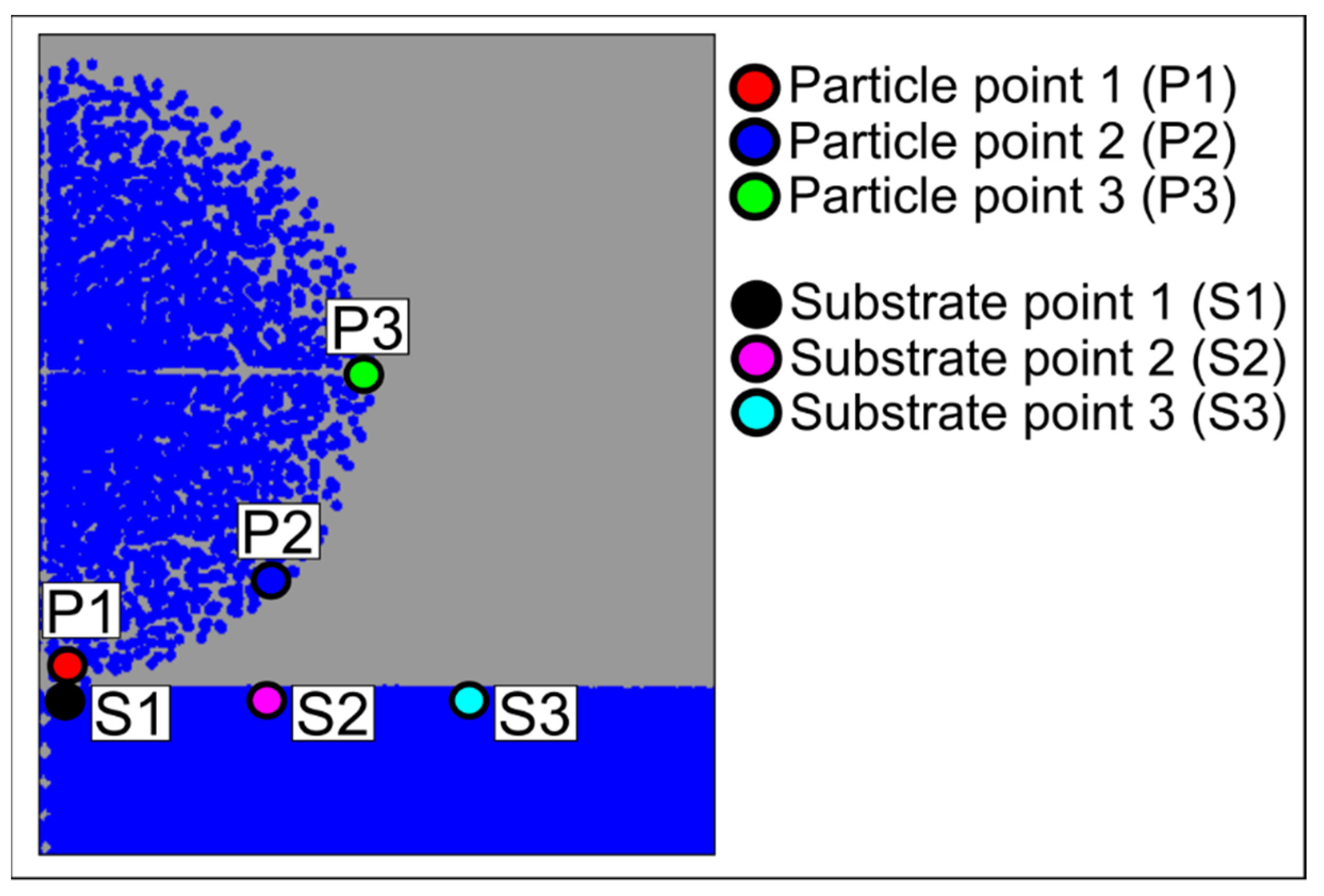
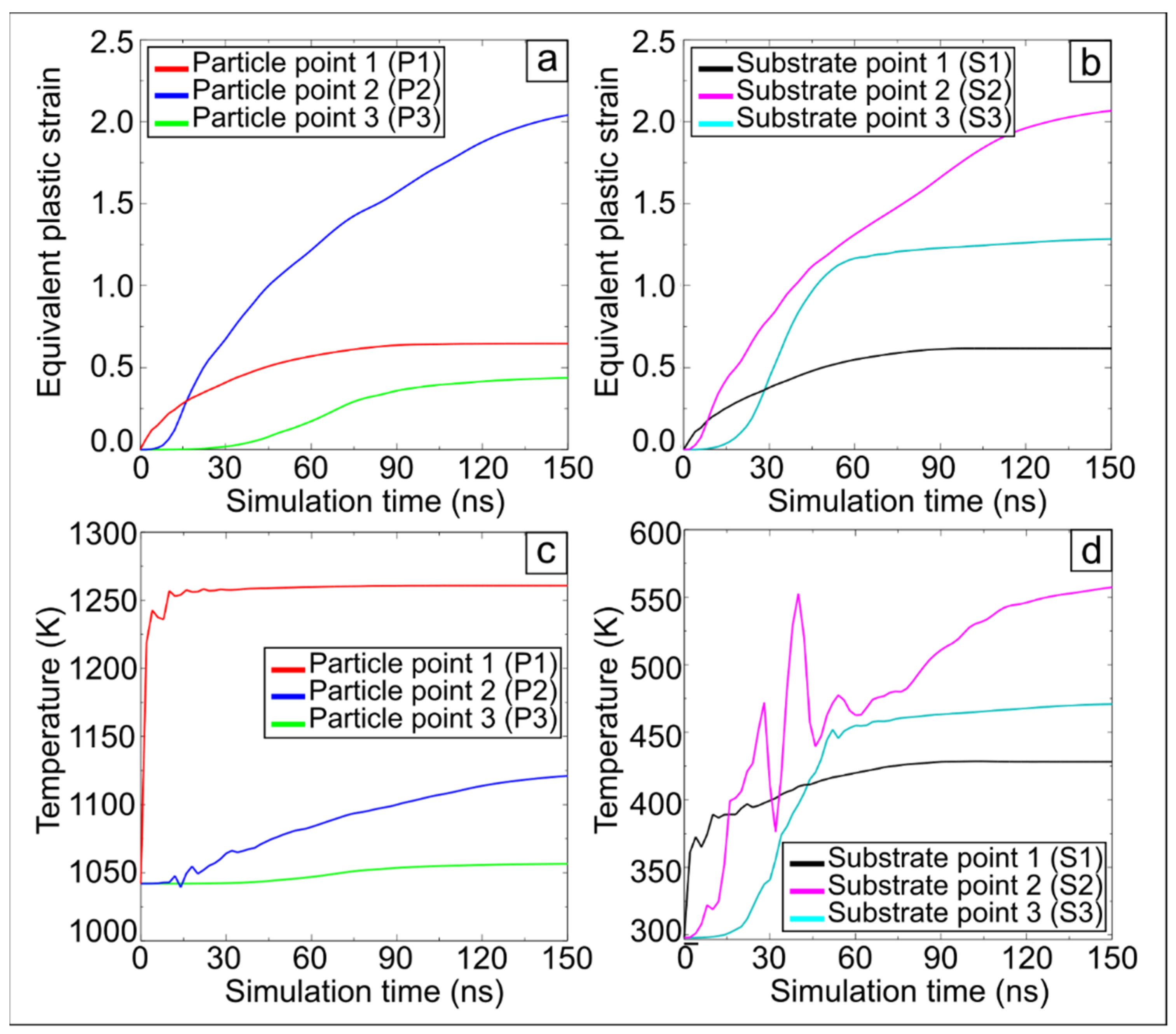
3.2.1. The Collision below the Melting Point

When colliding with the substrate, a particle that does not reach the melting temperature is plastically deformed. The plastic strain increases with time and reaches ε~3 near the particle/substrate boundary. The minimum value of the plastic strain (ε~0.3) is typical for the upper zone of the particle, which is farthest from the substrate. The particle has a domed shape and rises above the substrate’s surface. The splashing is not observed (Figure 6a) because the temperature and velocity of the particle are too low to initiate this process. To better understand the changes in temperature and strain that occur during the interaction of a particle and a substrate, it makes sense to study the process at several individual points. In this regard, two gauges were set directly in the center of the impact (P1, S1 in Figure 8) and four gauges were set at some distance from the center (P2, P3, S2, S3 in Figure 8, where P and S refer to the particle and the substrate, respectively).
At point P1 (the point of the particle closest to the substrate) in the time interval from 0 to 5 ns, a sharp spike in temperature (by 200 K) is observed, which is associated with the beginning of the particle deformation and the transition of its kinetic energy to heat (Figure 9c). After that, the temperature at point P1 increases monotonically and changes insignificantly. At points P2 and P3, the temperature increases for a longer time and its total increase is less compared to point P1 (Figure 9c). According to the calculations, different points of the particle are heated at rates ranging from 6 × 10⁸ K/s to 4 × 10¹⁰ K/s.
The substrate’s temperature at point S1 (Figure 9d) increases by 73 K. Its value monotonically increases and reaches 428 K after a short period of oscillation. The substrate temperature increases most significantly at point S2 (it rises from 300 to 510 K throughout the simulation period). It is obvious that at a certain initial temperature of the particle, below the melting temperature, and a certain initial velocity, such an increase in temperature is possible that partial melting occurs due to collision. According to the simulation results, this situation should be observed when the barrel is filled 35%, which corresponds to an initial velocity of 311 m/s and an initial temperature of 1042 K. In this case, the local temperature of the particle can rise to 1440 K due to collision.
The maximum strain (ε~2.0–2.2) takes place in points P2 and S2 at some distance from the center of impact (Figure 9a,b). This feature was previously observed in studies on the simulation of the cold spraying process [42,43]. The microvolumes of the material around points P1 and S1 are surrounded by a substantial amount of material and cannot move over significant distances in the radial direction. Simultaneously, due to the axial symmetry of the problem, the material around these points cannot move toward the symmetry axis. Therefore, the potential for significant shear at points P1 and S1 is limited. The material around points P2 and S2, oppositely, has more freedom of shear in the radial direction, which explains the observed phenomenon.
Noticeable deformation of points P3 and S3 more distant from the symmetry axis begins at t = 15–20 ns. This corresponds to the moment when the displacement of the material is equal to the particle radius. The strain of the particle and the substrate at the points in the central collision region, as well as at the points farthest from the collision zone, do not exceed ε~1.3.

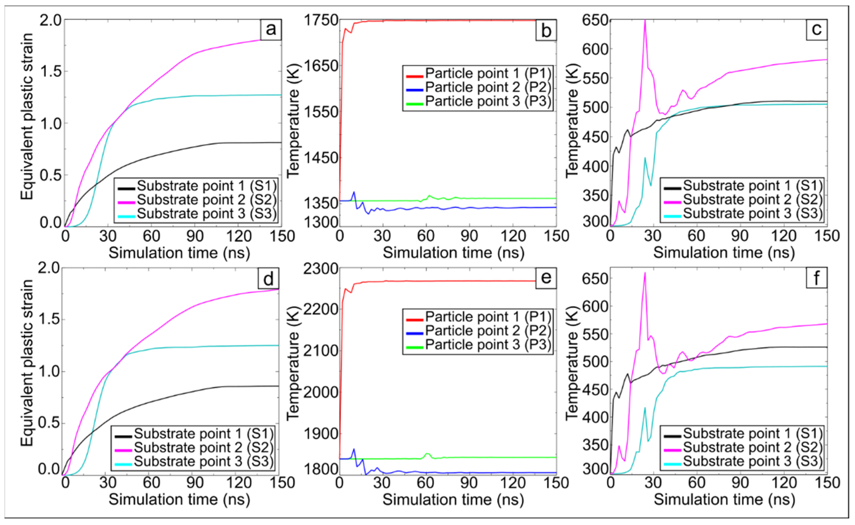
3.2.2. The Collision at Equal or above the Melting Point

As can be seen from Figure 6, there is no fundamental difference in the interaction between the particle and the substrate at a temperature equal to the melting point and above the melting point. Therefore, these two cases can be considered within one Section.
According to the Johnson–Cook equation, the yield strength of the material at the melting point is equal to zero. However, molten particles with higher velocity penetrate the substrate, which deforms more significantly than during the collision with the unmelted particles.
As in the previous case described in Section 3.2.1, an abrupt increase in temperature is observed at points S1 and S2 due to collision (Figure 10c,f). In this case, as the initial temperature and velocity of the particle increase, the magnitude of the temperature grows, and the heating rate also increases. The splashing phenomenon at the particle/substrate interface is observed at t = 25 ns. In the graphs illustrating the time dependence of strain, this phenomenon is expressed in a sharper increase in strain at point S3 from ε~0.2–0.3 to ε~1.2 (Figure 10a,d) at t = 25–40 ns. Maximum strain values at the chosen points reach ε~1.7–1.8.
Note that the substrate temperature does not exceed 660 K, even at high initial velocities and temperatures of the particle. Therefore, it follows from this simulation that there is no significant melting of the substrate material during detonation spraying.

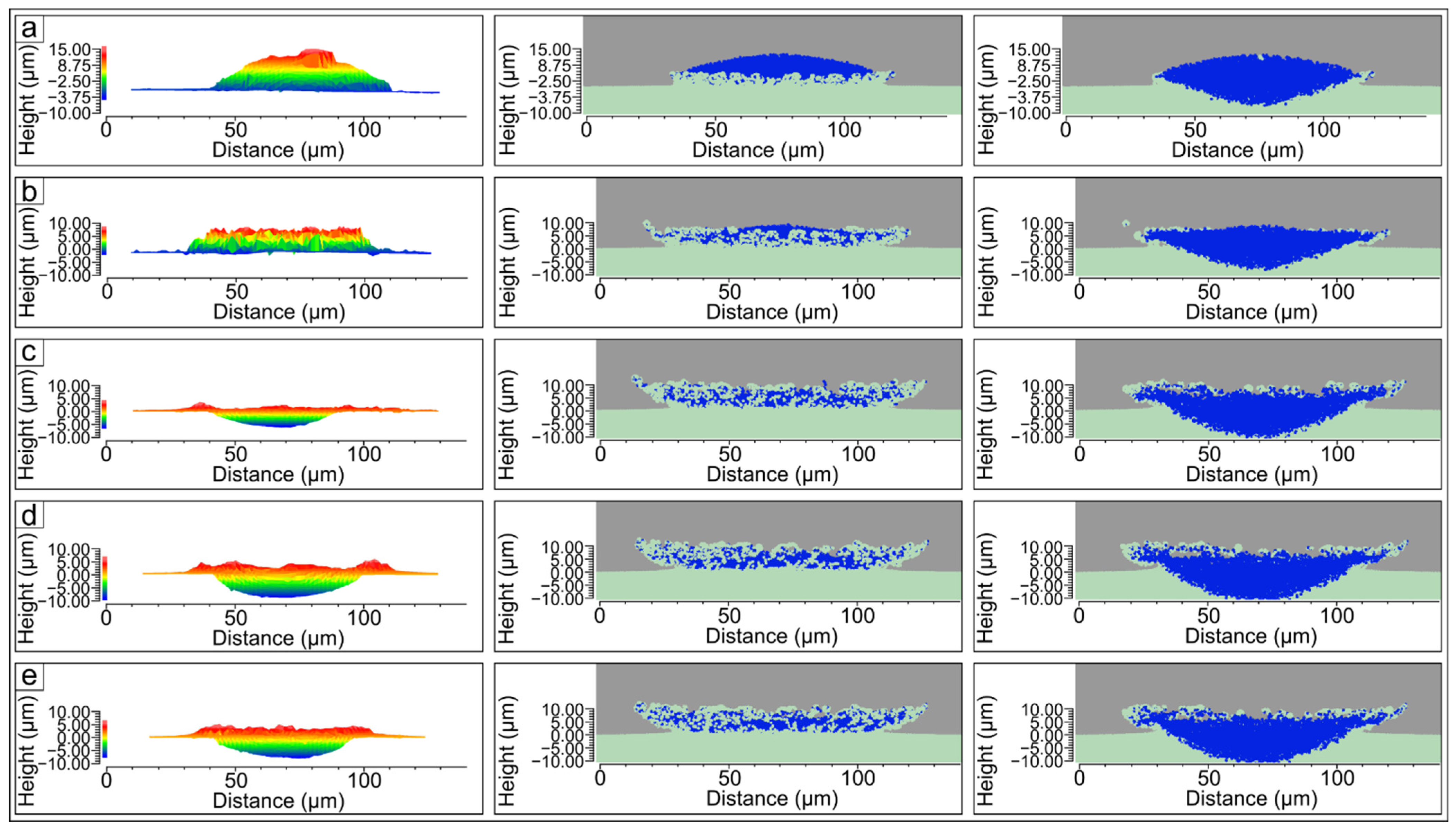
3.3. Comparison of SPH-Simulation Results and Experimental Data

Surface analysis of the samples using an optical interferometer was performed in the direction normal to the substrate. The 3D model obtained during the analysis allows us to evaluate the shape of the particle and the substrate in various sections. The obtained results were compared with the simulation results. In this regard, Figure 11 shows the experimental and simulation results on the same scale. According to Figure 11, the particles with a temperature below the melting point rise above the substrate. The flattering of the particles and their penetration into the substrate occurs when the particles’ temperature reaches and exceeds the melting point. The areas raised above the central zone of the crater are formed at its edges. Their formation might be explained by the extrusion of the substrate material (Figure 11c–e). The number of such areas increases with an increase in the temperature and velocity of the particle. Despite some difference between the shape of the simulated and experimentally formed splats, the experimentally observed geometry of the particles is in good agreement with the simulation results. Some discrepancy in the geometry may be due to the non-ideal shape of the particles in the experiment, as well as due to deviations in the materials parameters used in the simulation from the parameters of the real material. However, we found that the result obtained shows the effectiveness of SPH in simulating the processes that occur during detonation spraying.

4. Conclusions

The samples of the copper splats sprayed on the copper substrates were obtained using computer-controlled detonation spraying. The spraying parameters were chosen to provide unmelted, partially and completely melted particles. The single copper particle impact with the copper substrate was simulated using the SPH method. The initial conditions, namely the velocity and the temperature of the particle, were set in accordance with the experimental data. The following conclusions can be drawn.
1. The shape of the simulated splats agrees well with the experimental results. Particles that have not reached the melting point during spraying have a domed shape after collision. When the temperature of the particle is equal to or higher than the melting point, penetration in the substrate leads to the formation of the crater with raised edges. Thus, SPH simulation can be efficiently used to simulate detonation spraying.
2. Specific metal splashing around the crater occurs due to the interaction of partially or completely molten particles with the substrate. The splashing of the particle is observed at a distance of 20 µm from the crater.
3. The simulation results reveal that the collision process is accompanied by a spike in the particle’s temperature. Moreover, according to the calculations, different points of the particle are heated at rates ranging from 6 × 10⁸ K/s to 4 × 10¹⁰ K/s. The maximum temperature and deformation were observed at some distance from the center of the collision, at or near the edge of the craters.
4. During the impact at the certain spraying regimes, partial melting of the solid particle is possible. The temperature increase in the copper substrate during the collision does not exceed 660 K, even at high initial temperatures and velocities of the particles.

Author Contributions

Conceptualization, I.A.B. and V.Y.U.; Methodology, I.S.B., S.T. and P.A.R.; Investigation, P.A.R., A.A.R., Y.Y.E. and T.S.O.; Writing—original draft preparation, P.A.R. and I.A.B.; Writing—review and editing, V.Y.U., I.S.B., A.A.R. and I.A.B.; Supervision, V.A.B.; Project administration, I.A.B.; Funding acquisition, I.A.B. All authors have read and agreed to the published version of the manuscript.

Funding

This study was funded according to the Federal Task of Ministry of Education and Science of the Russian Federation (project FSUN-2020-0014 (2019-0931)): “Investigations of Metastable Structures Formed on Material Surfaces and Interfaces under Extreme External Impacts”.

Institutional Review Board Statement

Not applicable.

Informed Consent Statement

Not applicable.

Data Availability Statement

The data that support the findings of this study are available from the corresponding author upon reasonable request.

Acknowledgments

Research were conducted at core facility “Structure, mechanical and physical properties of materials” of Novosibirsk State Technical University (agreement with the Ministry of Science and Higher Education of the Russian Federation No. 13.CKP.21.0034, 075-15-2021-698).

Conflicts of Interest

The authors declare no conflict of interest.

References

  1. Tejero-Martin, D.; Rezvani Rad, M.; McDonald, A.; Hussain, T. Beyond Traditional Coatings: A Review on Thermal-Sprayed Functional and Smart Coatings. J. Therm. Spray Technol. 2019, 28, 598–644. [Google Scholar] [CrossRef] [Green Version]
  2. Ulianitsky, V.Y.; Batraev, I.S.; Shtertser, A.A.; Dudina, D.V.; Bulina, N.V.; Smurov, I. Detonation Spraying Behaviour of Refractory Metals: Case Studies for Mo and Ta-Based Powders. Adv. Powder Technol. 2018, 29, 1859–1864. [Google Scholar] [CrossRef]
  3. Chmielewski, T. Metallization of Aln Ceramic with Ti Using Detonation Spraying Process–Thermodynamic Approach. J. Manuf. Technol. 2018, 43, 11–19. [Google Scholar]
  4. Panin, S.; Vlasov, I.; Dudina, D.; Ulyanitsky, V.; Stankevich, R.; Batraev, I.; Maruschak, P.; Landová, M. Deposition of Titanium Based Coatings by Reactive Detonation Spraying. Koroze Ochr. Materiálu 2018, 62, 6–13. [Google Scholar] [CrossRef] [Green Version]
  5. Senderowski, C.; Chodala, M.; Bojar, Z. Corrosion Behavior of Detonation Gun Sprayed Fe-Al Type Intermetallic Coating. Materials 2015, 8, 1108–1123. [Google Scholar] [CrossRef] [PubMed] [Green Version]
  6. Dudina, D.V.; Korchagin, M.A.; Zlobin, S.B.; Ulianitsky, V.Y.; Lomovsky, O.I.; Bulina, N.V.; Bataev, I.A.; Bataev, V.A. Compositional Variations in the Coatings Formed by Detonation Spraying of Ti3Al at Different O2/C2H2 Ratios. Intermetallics 2012, 29, 140–146. [Google Scholar] [CrossRef]
  7. Kuchumova, I.; Batraev, I.; Cherkasova, N.; Ukhina, A.; Shtertser, A.; Jorge, A.M. The Influence of Salt Fog Exposure on Corrosion Resistance of Detonation Coatings Fe66Cr10Nb5B19. Met. Work. Mater. Sci. 2020, 22, 95–105. [Google Scholar] [CrossRef]
  8. Oliker, V.E.; Abdurashitova, S.A.; Martsenyuk, I.S.; Grechishkin, E.F.; Bondarenko, A.A. Microstructure and Properties of Detonation-Sprayed Thermal Barrier ZrO2 Coatings. Powder Metall. Met. Ceram. 2013, 52, 83–89. [Google Scholar] [CrossRef]
  9. Babu, P.S.; Sen, D.; Jyothirmayi, A.; Krishna, L.R.; Rao, D.S. Influence of Microstructure on the Wear and Corrosion Behavior of Detonation Sprayed Cr2O3-Al2O3 and Plasma Sprayed Cr2O3 Coatings. Ceram. Int. 2018, 44, 2351–2357. [Google Scholar] [CrossRef]
  10. Ulianitsky, V.; Shtertser, A.; Batraev, I. Electrical Insulation Properties of Aluminum Oxide Detonation Coatings. Met. Work. Mater. Sci. 2018, 20, 83–95. [Google Scholar] [CrossRef]
  11. Kantay, N.; Rakhadilov, B.; Kurbanbekov, S.; Yeskermessov, D.; Yerbolatova, G.; Apsezhanova, A. Influence of Detonation-Spraying Parameters on the Phase Composition and Tribological Properties of Al2O3 Coatings. Coatings 2021, 11, 793. [Google Scholar] [CrossRef]
  12. Du, H.; Hua, W.; Liu, J.; Gong, J.; Sun, C.; Wen, L. Influence of Process Variables on the Qualities of Detonation Gun Sprayed WC–Co Coatings. Mater. Sci. Eng. A 2005, 408, 202–210. [Google Scholar] [CrossRef]
  13. Babu, P.S.; Rao, P.C.; Jyothirmayi, A.; Phani, P.S.; Krishna, L.R.; Rao, D.S. Evaluation of Microstructure, Property and Performance of Detonation Sprayed WC-(W, Cr)2C-Ni Coatings. Surf. Coat. Technol. 2018, 335, 345–354. [Google Scholar] [CrossRef]
  14. Du, H.; Sun, C.; Hua, W.G.; Zhang, Y.S.; Han, Z.; Wang, T.G.; Gong, J.; Lee, S.W. Fabrication and Evaluation of D-Gun Sprayed WC–Co Coating with Self-Lubricating Property. Tribol. Lett. 2006, 23, 261–266. [Google Scholar] [CrossRef]
  15. Smurov, I.; Ulianitsky, V. Computer Controlled Detonation Spraying: A Spraying Process Upgraded to Advanced Applications. Surf. Eff. Contact Mech. 2011, 10, 265–276. [Google Scholar]
  16. Ulianitsky, V.Y.; Nenashev, M.V.; Kalashnikov, V.V.; Ibatullin, I.D.; Ganigin, S.Y.; Yakunin, K.P.; Rogozhin, P.V.; Shtertser, A.A. Opyt Issledovanija i Primenenija Tehnologii Nanesenija Detonacionnyh Pokrytij. Izvestija Samarskogo Nauchnogo Centra Rossijskoj Akademii Nauk 2010, 12, 569–575. [Google Scholar]
  17. Yildirim, B.; Muftu, S.; Gouldstone, A. Modeling of High Velocity Impact of Spherical Particles. Wear 2011, 270, 703–713. [Google Scholar] [CrossRef]
  18. Li, W.-Y.; Zhang, C.; Li, C.-J.; Liao, H. Modeling Aspects of High Velocity Impact of Particles in Cold Spraying by Explicit Finite Element Analysis. J. Therm. Spray Technol. 2009, 18, 921–933. [Google Scholar] [CrossRef]
  19. Li, W.-Y.; Liao, H.; Li, C.-J.; Li, G.; Coddet, C.; Wang, X. On High Velocity Impact of Micro-Sized Metallic Particles in Cold Spraying. Appl. Surf. Sci. 2006, 253, 2852–2862. [Google Scholar] [CrossRef]
  20. Manap, A.; Okabe, T.; Ogawa, K. Computer Simulation of Cold Sprayed Deposition Using Smoothed Particle Hydrodynamics. Procedia Eng. 2011, 10, 1145–1150. [Google Scholar] [CrossRef] [Green Version]
  21. Xie, J.; Nélias, D.; Berre, W.-L.; Ogawa, K.; Ichikawa, Y. Simulation of the Cold Spray Particle Deposition Process. J. Tribol. 2015, 137, 041101. [Google Scholar] [CrossRef] [Green Version]
  22. Suresh, S.; Lee, S.-W.; Aindow, M.; Brody, H.D.; Champagne, V.K.; Dongare, A.M. Mesoscale Modeling of Jet Initiation Behavior and Microstructural Evolution during Cold Spray Single Particle Impact. Acta Mater. 2020, 182, 197–206. [Google Scholar] [CrossRef]
  23. Yin, S.; Wang, X.; Suo, X.; Liao, H.; Guo, Z.; Li, W.; Coddet, C. Deposition Behavior of Thermally Softened Copper Particles in Cold Spraying. Acta Mater. 2013, 61, 5105–5118. [Google Scholar] [CrossRef]
  24. Nikolaev, Y.A.; Vasil’ev, A.A.; Ul’yanitskii, B.Y. Gas Detonation and Its Application in Engineering and Technologies. Combust. Explos. Shock Waves 2003, 39, 382–410. [Google Scholar] [CrossRef]
  25. Batraev, I.S.; Ulianitsky, V.Y.; Dudina, D.V. Detonation Spraying of Copper: Theoretical Analysis and Experimental Studies. Mater. Today Proc. 2017, 4, 11346–11350. [Google Scholar] [CrossRef]
  26. Ulianitsky, V.Y.; Dudina, D.V.; Shtertser, A.A.; Smurov, I. Computer-Controlled Detonation Spraying: Flexible Control of the Coating Chemistry and Microstructure. Metals 2019, 9, 1244. [Google Scholar] [CrossRef] [Green Version]
  27. Gavrilenko, T.P.; Nikolaev, Y.A. Calculation of Detonation Gas Spraying. Combust. Explos. Shock Waves 2007, 43, 724–731. [Google Scholar] [CrossRef]
  28. Émurlaeva, Y.Y.; Bataev, I.A.; Zhou, Q.; Lazurenko, D.V.; Ivanov, I.V.; Riabinkina, P.A.; Tanaka, S.; Chen, P. Welding Window: Comparison of Deribas’ and Wittman’s Approaches and SPH Simulation Results. Metals 2019, 9, 1323. [Google Scholar] [CrossRef] [Green Version]
  29. Bataev, I. Structure of Explosively Welded Materials: Experimental Study and Numerical Simulation. Met. Work. Mater. Sci. 2017, 77, 55–67. [Google Scholar] [CrossRef]
  30. Nassiri, A.; Abke, T.; Daehn, G. Investigation of Melting Phenomena in Solid-State Welding Processes. Scr. Mater. 2019, 168, 61–66. [Google Scholar] [CrossRef]
  31. Chen, X.; Li, X.; Inao, D.; Tanaka, S.; Hokamoto, K. Study of Explosive Welding of A6061/SUS821L1 Using Interlayers with Different Thicknesses and the Air Shockwave between Plates. Int. J. Adv. Manuf. Technol. 2021, 116, 3779–3794. [Google Scholar] [CrossRef]
  32. Li, Y.; Liu, C.; Yu, H.; Zhao, F.; Wu, Z. Numerical Simulation of Ti/Al Bimetal Composite Fabricated by Explosive Welding. Metals 2017, 7, 407. [Google Scholar] [CrossRef] [Green Version]
  33. Geng, H.; Mao, J.; Zhang, X.; Li, G.; Cui, J. Formation Mechanism of Transition Zone and Amorphous Structure in Magnetic Pulse Welded Al-Fe Joint. Mater. Lett. 2019, 245, 151–154. [Google Scholar] [CrossRef]
  34. Zhang, S.; Lueg-Althoff, J.; Hahn, M.; Tekkaya, A.E.; Kinsey, B. Effect of Process Parameters on Wavy Interfacial Morphology During Magnetic Pulse Welding. J. Manuf. Sci. Eng. 2021, 143, 011010. [Google Scholar] [CrossRef]
  35. Lueg-Althoff, J.; Bellmann, J.; Gies, S.; Schulze, S.; Tekkaya, A.E.; Beyer, E. Influence of the Flyer Kinetics on Magnetic Pulse Welding of Tubes. J. Mater. Process. Technol. 2018, 262, 189–203. [Google Scholar] [CrossRef]
  36. Zhang, Z.L.; Feng, D.L.; Liu, M.B. Investigation of Explosive Welding through Whole Process Modeling Using a Density Adaptive SPH Method. J. Manuf. Process. 2018, 35, 169–189. [Google Scholar] [CrossRef]
  37. Alhussan, K.A.; Babenko, V.A.; Kozlov, I.M.; Smetannikov, A.S. Development of Modified SPH Approach for Modeling of High-Velocity Impact. Int. J. Heat Mass Transf. 2012, 55, 6340–6348. [Google Scholar] [CrossRef]
  38. Hassani-Gangaraj, M.; Veysset, D.; Champagne, V.K.; Nelson, K.A.; Schuh, C.A. Adiabatic Shear Instability Is Not Necessary for Adhesion in Cold Spray. Acta Mater. 2018, 158, 430–439. [Google Scholar] [CrossRef]
  39. Batraev, I.S.; Prohorov, E.S.; Ulianitsky, V.Y. Razgon I Nagrev Poroshkovyh Chastic Produktami Gazovoj Detonacii V Kanalah S Konicheskim Perehodom. Combust. Explos. Shock Waves 2014, 50, 315–322. (In Russian) [Google Scholar] [CrossRef]
  40. Ulianitsky, V.; Batraev, I.; Dudina, D.; Smurov, I. Enhancing the Properties of WC/Co Detonation Coatings Using Two-Component Fuels. Surf. Coat. Technol. 2017, 318, 244–249. [Google Scholar] [CrossRef]
  41. Ulianitsky, V.Y.; Batraev, I.S.; Shtertser, A.A. Detonacionnye pokrytija iz oksidov. Uprochnjajushhie Tehnologii I Pokrytija 2015, 9, 37–44. (In Russian) [Google Scholar]
  42. King, P.C.; Bae, G.; Zahiri, S.H.; Jahedi, M.; Lee, C. An Experimental and Finite Element Study of Cold Spray Copper Impact onto Two Aluminum Substrates. J. Therm. Spray Technol. 2010, 19, 620–634. [Google Scholar] [CrossRef]
  43. Assadi, H.; Gärtner, F.; Stoltenhoff, T.; Kreye, H. Bonding Mechanism in Cold Gas Spraying. Acta Mater. 2003, 51, 4379–4394. [Google Scholar] [CrossRef]
Figure 1. Initial copper powder (a) and the histogram of the particle size distribution (b).
Metals 12 01013 g001
Figure 2. Scheme of the computational domain.
Metals 12 01013 g002
Figure 3. Convergence plot for maximum plastic strain.
Metals 12 01013 g003
Figure 4. The shape of copper particles after impact with the substrate at the barrel filling volume of 35% (a,b), 40% (c,d), 50% (e,f), 60% (g,h), 65% (i,j).
Metals 12 01013 g004
Figure 5. The crater formed during the impact of the underheated particle and the substrate (a); material’s splashing due to the overheating of the fine particle (b).
Metals 12 01013 g005
Figure 6. The changes of the shape and plastic strain of the particle during collision with the substrate at 35% (a), 50% (b) and 65% (c) of the barrel filling volume with explosive mixture.
Metals 12 01013 g006
Figure 7. The penetration depth of the particles during various spraying regimes.
Metals 12 01013 g007
Figure 8. Arrangement of point gauges for the analysis of temperature and deformation changes.
Metals 12 01013 g008
Figure 9. Time dependence of the plastic strain and temperature at points P1, P2, P3 of the particle (a,c) and S1, S2, S3 of the substrate (b,d) during impact at temperatures below the particle melting point (barrel filling 35%, T = 1042 K, V = 311 m/s).
Metals 12 01013 g009
Figure 10. Time dependence of the plastic strain and temperature at points P1, P2, P3 of the copper particle (b,e) and S1, S2, S3 of the substrate (a,c,d,f) during the simulation of collision when the particle’s temperature reaches the melting point (ac) and above the melting point (df).
Metals 12 01013 g010
Figure 11. Comparison of the experimental and simulated shape of the particle at the barrel filling volume of 35% (a), 40% (b), 50% (c), 60% (d), 65% (e). The left row shows the side view of the particle obtained using an optical interferometer. The middle and the right rows show the side view and the cross section through the middle of the particle, respectively.
Metals 12 01013 g011
Table 1. Detonation spraying regimes.
Volume of the Barrel Filling with Explosive Mixture *, %T, KV, m/s
651839402
601558405
501356389
401231338
351042311
* With respect to the total volume of the barrel.
Table 2. Copper parameters for Johnson–Cook and Mie–Grüneisen equations used in the calculation.
ParameterValueUnits
Density8900kg/m3
Shear modulus44.7GPa
Thermal conductivity386.5W/m∙K
Specific heat383J/kg∙K
Sound speed3940m/s
Parameter S1.489-
Grüneisen parameter, Г02.02-
Yield stress, A90MPa
Hardening constant, B292MPa
Hardening exponent associated with quasi-static test, n0.31-
Strain rate constant, C0.025-
Thermal softening exponent, m1.09-
Melting temperature1356K
Publisher’s Note: MDPI stays neutral with regard to jurisdictional claims in published maps and institutional affiliations.

