Article

Mechanical Properties of Explosion-Welded Titanium/Duplex Stainless Steel under Different Energetic Conditions

1
State Key Laboratory of Precision Blasting, Jianghan University, Wuhan 430056, China
2
Hubei Province Key Laboratory of Engineering Blasting, Jianghan University, Wuhan 430056, China
3
Faculty of Advanced Science and Technology, Kumamoto University, Kumamoto 860-8555, Japan
4
Institute of Industrial Nanomaterials, Kumamoto University, Kumamoto 860-8555, Japan
5
State Key Laboratory of Structural Analysis for Industrial Equipment, Department of Engineering Mechanics, Dalian University of Technology, Dalian 116024, China
6
SINOPEC Dalian Research Institute of Petroleum and Petrochemicals, Dalian 116045, China
*
Authors to whom correspondence should be addressed.
Metals 2022, 12(8), 1354; https://doi.org/10.3390/met12081354
Submission received: 19 July 2022 / Revised: 9 August 2022 / Accepted: 12 August 2022 / Published: 15 August 2022
(This article belongs to the Special Issue Explosive Welding and Impact Mechanics of Metal and Alloys)

Abstract

:
In this study, the energy deposited at the welding interface was controlled by changing the stand-off between the flyer and base plates. Pure titanium (TP 270C) and duplex stainless steel (SUS 821L1) were welded under 5- and 15-mm stand-offs, respectively. When the stand-off was 5 mm, the average wavelength and average amplitude of the welding interface were 271 and 61 μm, respectively; at 15 mm stand-off, the average wavelength and average amplitude of the welding interface were 690 and 192 μm, respectively. The differences between the two welding conditions were compared using a tensile test, fracture analysis, a 90° bending test, Vickers hardness, and nanoindentation related to the mechanical properties of materials. The experimental results indicated that the sample with a 5-mm stand-off had better mechanical properties.

1. Introduction

Explosive welding is a processing technology that uses the energy of an explosion to make two dissimilar metal plates dissolve together [1,2,3]. Based on numerous experiments, researchers have proposed the hypothesis of an explosive weldability window [4,5,6,7]. The welding can be achieved when the welding parameters are in this window. When the parameters are outside the window, the welding may fail. Currently, it is believed that a good welding result will be obtained when the welding parameter is a little above the lower boundary of the window. Features slightly above the boundary are the formation of a small wavy interface and a small vortex area; when the parameter is raised above, the wavy interface and vortex area increase due to increased energy deposition at the interface. Many studies have been conducted on the interface morphology under different energy conditions. For example, Manikandan et al. studied explosion-welded titanium–stainless steel [8,9], Habib et al. studied titanium–magnesium alloy [10], Shi et al. studied steel–stainless steel [11], Zhou studied tungsten–copper [12], and Carvalho et al. studied aluminum–copper [13]. In our previous research, we studied the interface morphologies of explosion-welded aluminum alloy high-strength-duplex stainless steel [14,15], titanium-duplex stainless steel [16,17], and magnesium-duplex stainless steel [18] under different energy conditions.
However, there have been few studies evaluating the various mechanical properties of weldments under different energy conditions [19]. Stand-off is the distance between two plates in explosive welding. Under the same detonation velocity, changing the stand-off can change the energy deposited at the interface [17]. In this study, two welding results of pure titanium (TP 270C) and duplex stainless steel (SUS 821L1) were obtained by changing the stand-off. One was with relatively small energy (the welding parameters were near the lower limit of the weldability window) and the other was with a higher energy (the welding parameters had a certain distance above the lower limit of the weldability window). Finally, the differences in the macro- and micro-mechanical properties of weldments under the two welding conditions were compared.

2. Materials and Methods

JIS TP 270C and SUS 821L1 (austenite and ferrite) were used in the study. These two materials have very good corrosion resistance. The structural parts of titanium and stainless steel are used in aerospace engineering, chemical and petrochemical industries, heat exchangers, nuclear reactors and nuclear fuel reprocessing. The size of the plates was 200 mm (length) × 100 mm (width) × 3 mm (height). The chemical composition of the joined materials was provided in [16]. The main explosive used in the experiment was ANFO-A (a mixture of ammonium nitrate and fuel oil), with a density of approximately 530 kg/m3; the detonation velocity was approximately 2575 m/s [8]. A schematic of explosive welding is shown in Figure 1. The thickness of the explosive used in the study was 48 mm. The gaps between titanium and duplex stainless steels were set at 5 and 15 mm, respectively.
The part 15 mm from both sides was used for mechanical property testing. The lengths of the tensile and 90° bending test specimens were the same as those of the original plates. The Vickers hardness and nanoindentation samples were taken from positions about 150 mm from the initiation point and 50 mm from the side. The mechanical properties of the two weldments were comprehensively evaluated using a tensile test, 3D full-field strain measurement and analysis system, fracture analysis, 90° bending, Vickers hardness analysis and nanoindentation analysis. The wavy interface was observed by optical microscopy; fracture analysis was performed using an optical microscope (Nikon, Tokyo, Japan) and a scanning electron microscope (Zeiss, Oberkochen, Germany). After 90° bending, Vickers hardness analysis and nanoindentation analysis results were examined by optical microscopy.

3. Results and Discussion

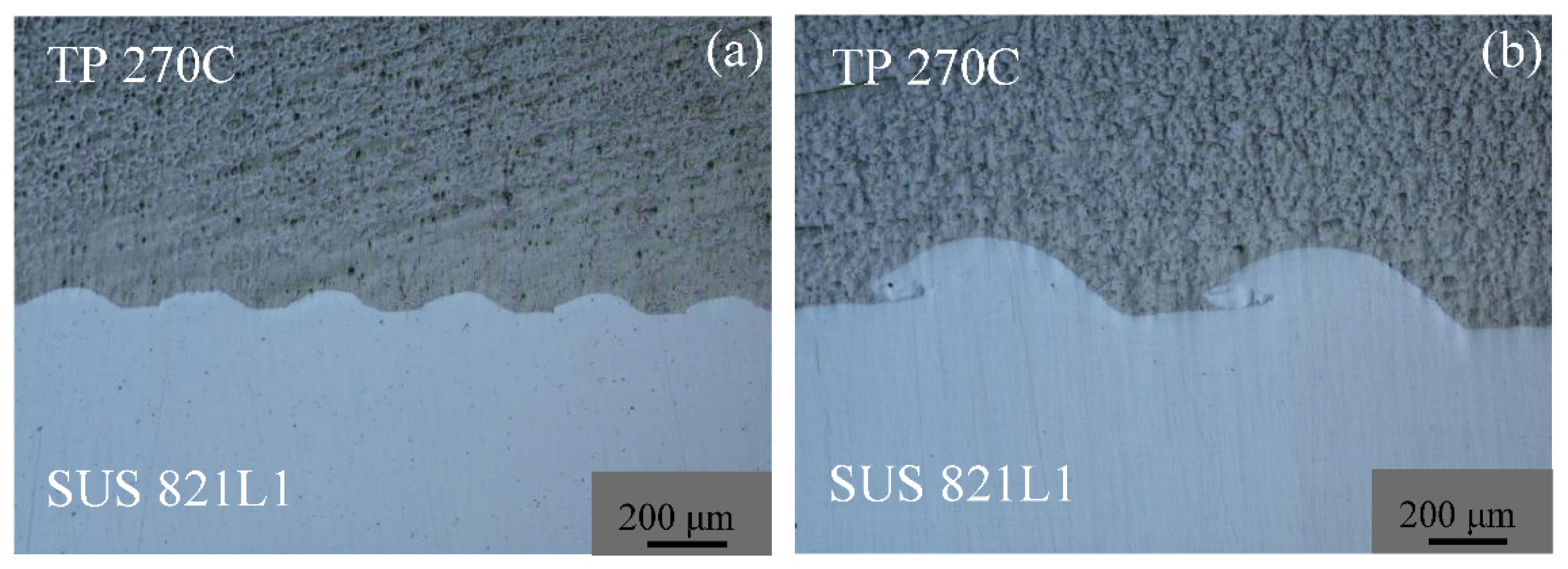
3.1. Morphology of the Welding Interface
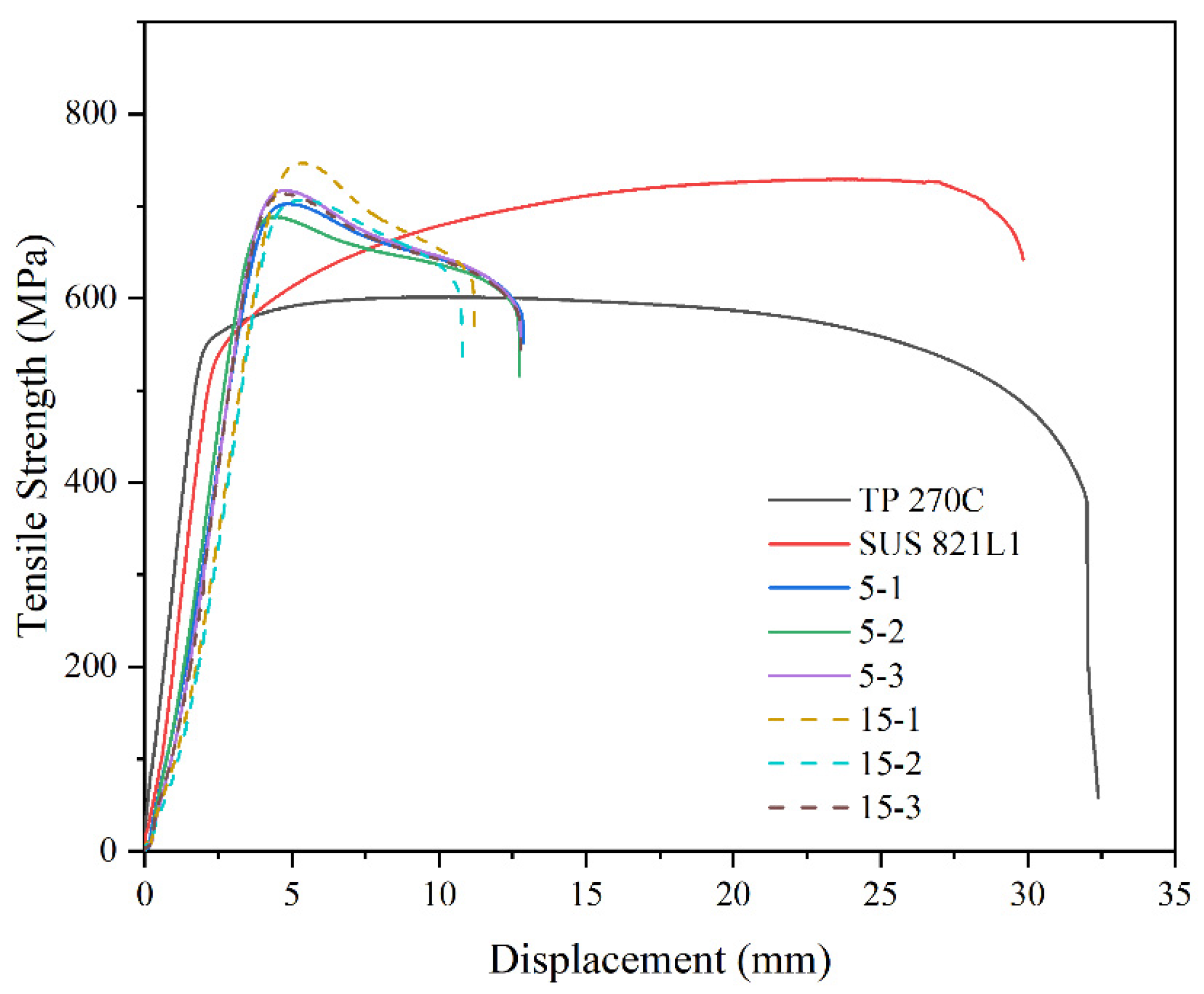
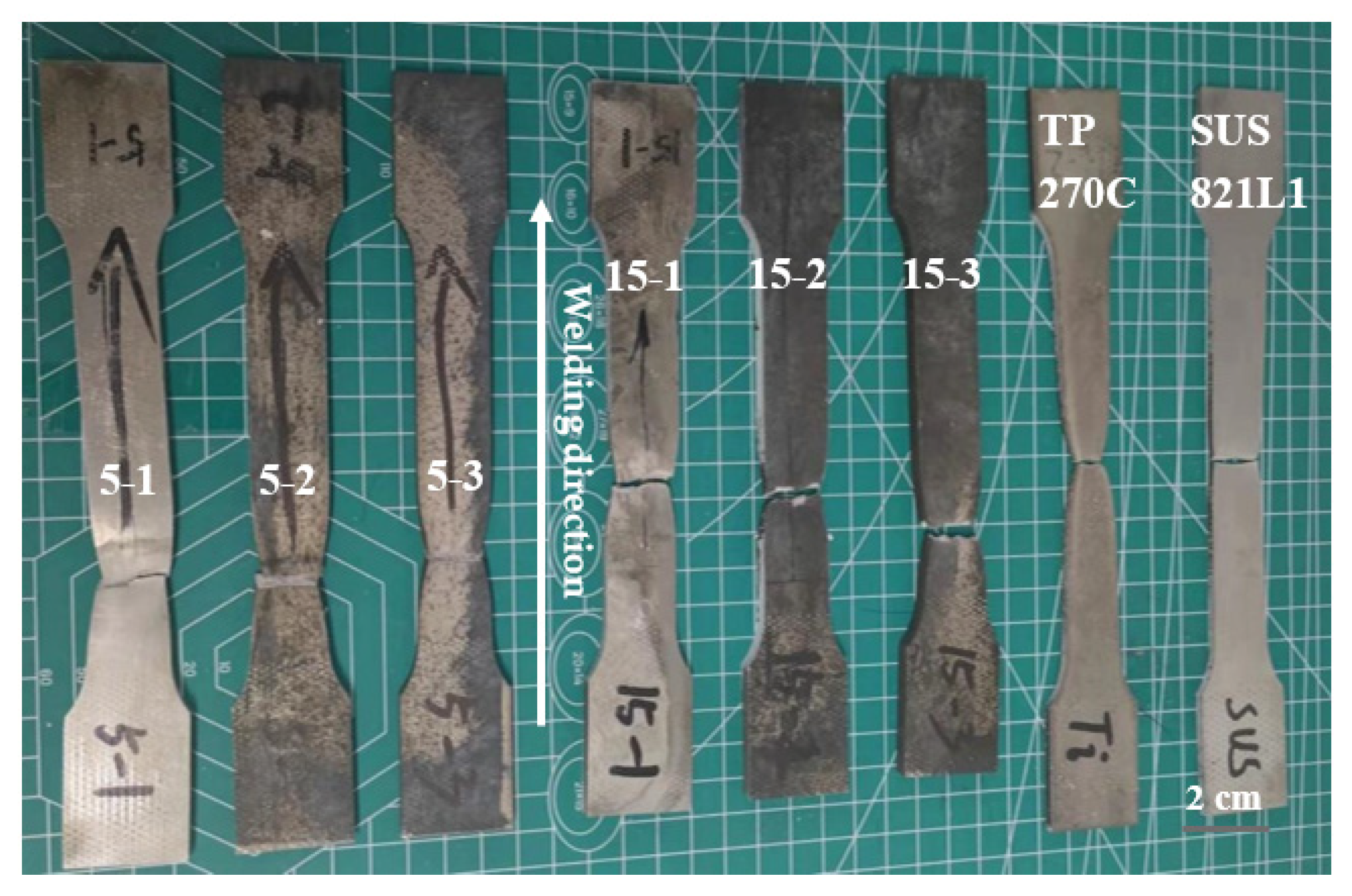
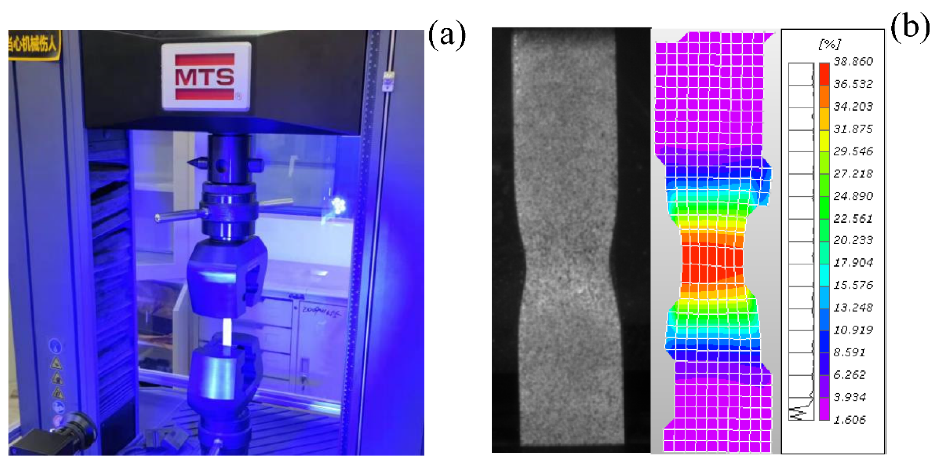
The sizes of the interface waves are shown in Figure 2. When the stand-off was 15 mm, the average wavelength and average amplitude of the welding interface were 271 and 61 μm, respectively; when the stand-off was 15 mm, the average wavelength and average amplitude of the welding interface were 690 and 192 μm, respectively. There was a small difference in wavelength and wave height in the same sample. Before welding, 600-grit SiC paper was used to polish the welding surface, resulting in an uneven welding surface, affecting the process of jetting, the shapes of waves and the melting zone; the different shapes of the waves and melting zone may also be related to the vibration caused by the collision.

3.2. Tensile Test

Tensile tests were conducted on the original materials and welded plates. The results are shown in Figure 3 and Table 1. Theoretically, the tensile strength of the composite plate should be between the strengths of the two original plates [20]. Sometimes, the tensile strength of weldments is higher than that of two original metals [21], which is due to the work hardening effect of explosive welding. Here, the strength of the composite plate was close to that of SUS 821L1. With a 15-mm stand-off, the tensile strength of both samples was slightly higher than that of the sample with a 5-mm stand-off, which was due to the more severe work hardening of the weldment with a large interfacial wave. From the perspective of stability, the tensile strength of weldments with small waves was more stable. It can be seen from Figure 3 that, compared with the original materials, the plasticity of the weldments decreased; the greater the wave, the poorer the plasticity, which was related to the degree of work hardening.
A tensile test of the composite plate is a way to evaluate the mechanical properties of explosive welding materials [22]. In this study, a 3D full-field strain measurement and analysis system (digital image correlation method) were used to record the changing process of strain during stretching. The maximum strain on the duplex stainless steel side of the sample with a 5-mm stand-off was 0.48, and no data was obtained on the titanium side due to paint falling off. The maximum strain on the duplex stainless steel side of the sample with a 15-mm stand-off was 0.42, and the maximum strain on the titanium side was 0.39. It can be seen from the data on the duplex stainless-steel side that the sample with a 5-mm stand-off had greater ability to resist plastic deformation, which is consistent with the results reflected in the tensile curve in Figure 3. The photos of the 3D full-field strain measurement and analysis process are shown in Figure 4. Figure 5 shows the samples after the tensile test.

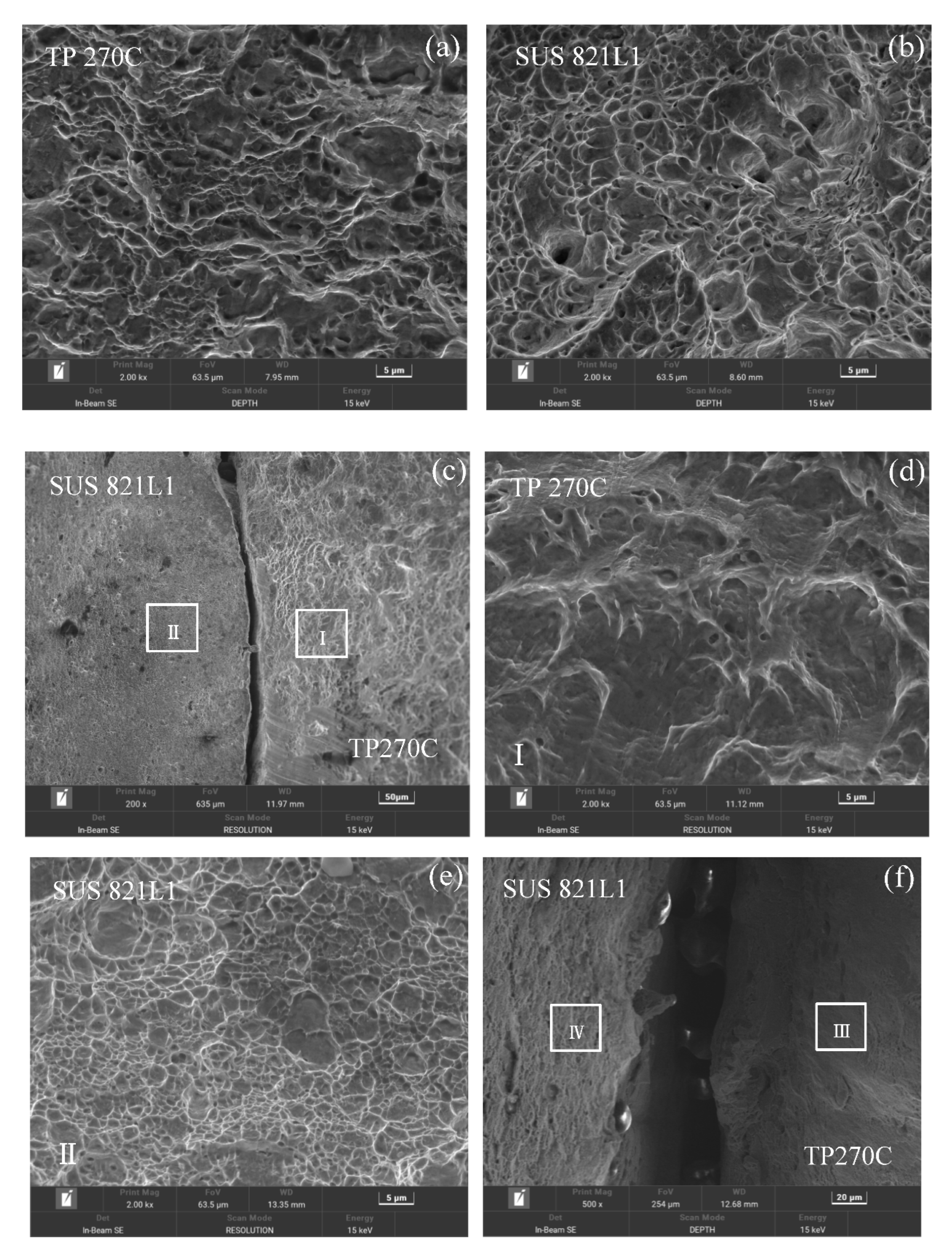
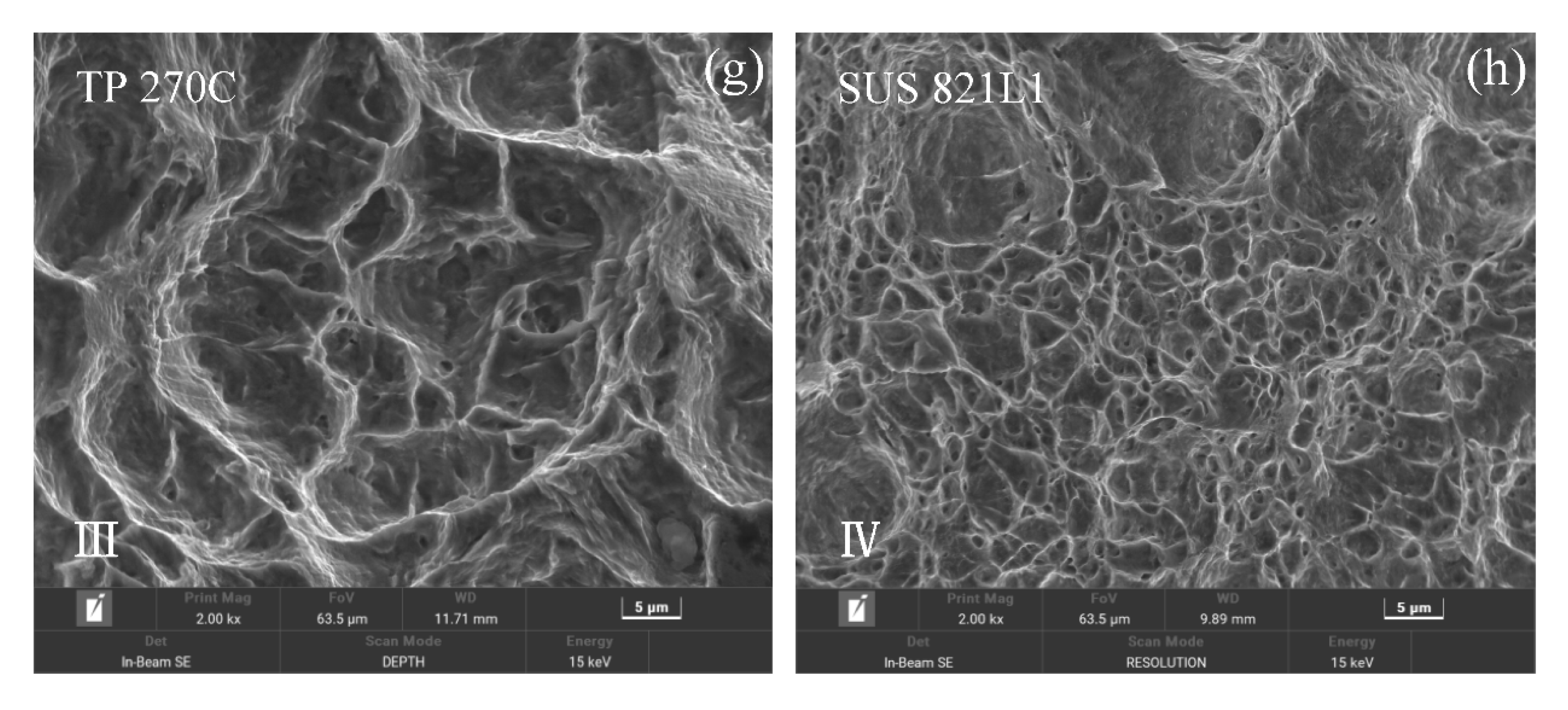
3.3. Fracture Analysis
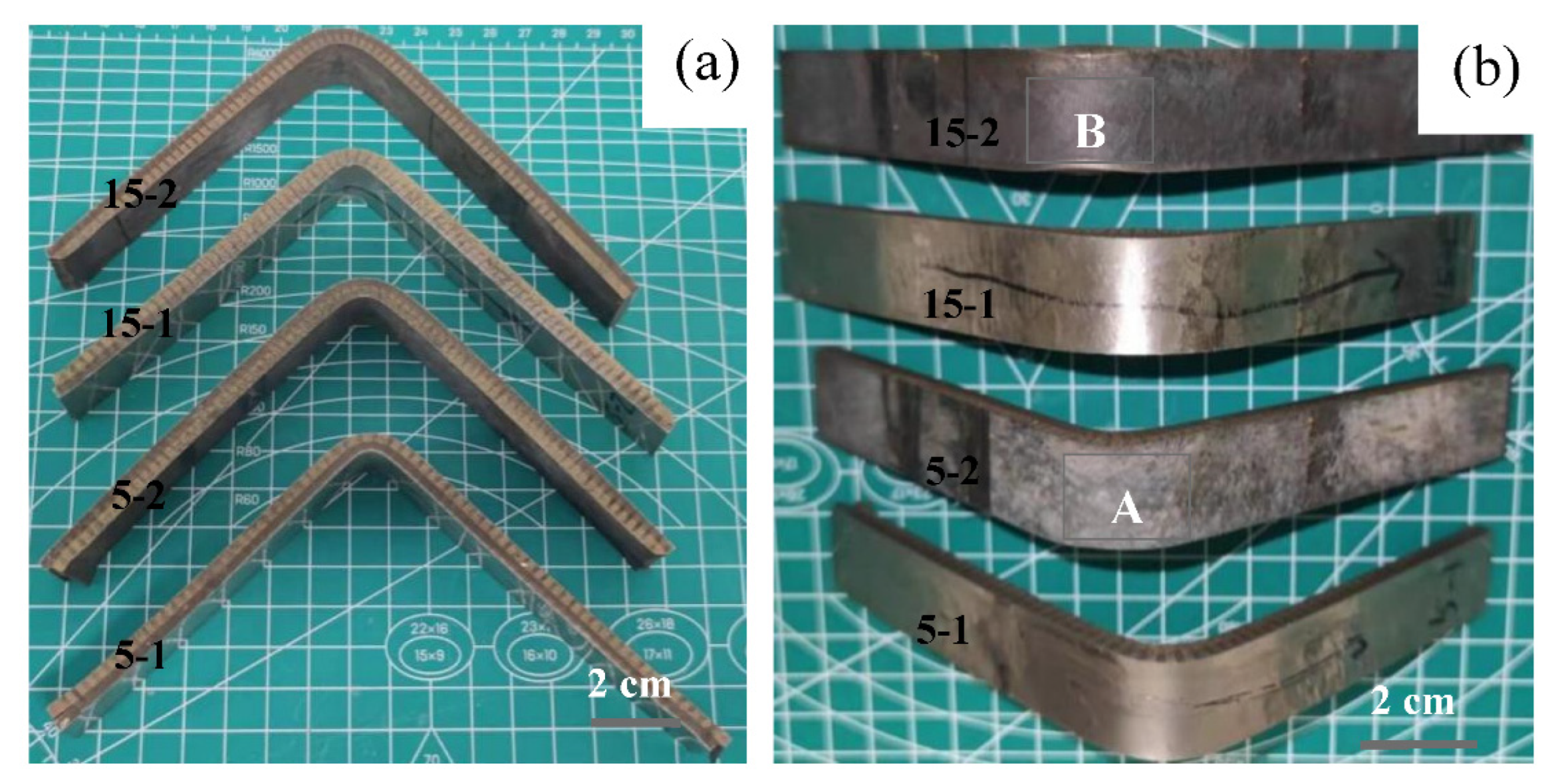
In Figure 6a, a fracture crack in the sample with a 15-mm stand-off was introduced into the welding interface, resulting in the separation of the welding interface. This was related to excessive residual stress and excessive melting. No obvious macro-crack was found on the welding interface of the sample with a 5-mm stand-off. According to Figure 6b, the macro-fracture of the sample with a 5-mm stand-off was inclined, and the macro-fracture of the sample with a 15-mm stand-off was concave to the welding interface.
As shown in Figure 7, the fracture of the original SUS 821L1 and TP 270C samples was full of dimples and cavities, characteristic of plastic material fracture. The cracks between the composite plates with a 15-mm stand-off were larger than those between composite plates with a 5-mm stand-off. Although both titanium and duplex stainless steel are ductile when stretched alone, the fracture of the composite plate shows that the duplex stainless-steel side remained ductile, and the fracture was full of dimples and cavities. However, the titanium side evidenced the characteristics of brittle fracture, and the fracture mainly presented a quasi-cleavage morphology.

3.4. Bending Test

A bending test is often used to evaluate the deformation resistance of explosive weldments [23,24]. In this study, the specimen was subjected to a 90° bending test. The size of the sample was 200 mm × 20 mm × 6 mm. The test results are shown in Figure 8. When stand-off equaled 5 mm, in region A, no crack appeared at the welding interface; when the stand-off equaled 15 mm, in region B, a crack appeared at the welding interface—the crack was induced by a large deformation, meaning a small wavy interface had stronger resistance to large plastic deformation.

3.5. Vickers Hardness

Results of the Vickers hardness tests are shown in Figure 9. A loading of 0.2 kgf was used to measure the hardness. The hardness of duplex stainless steel increased near the interface, which was caused by large plastic deformation. Whether there was an increase in the hardness of titanium near the interface was unclear. The hardness increase of titanium near the interface is not obvious.

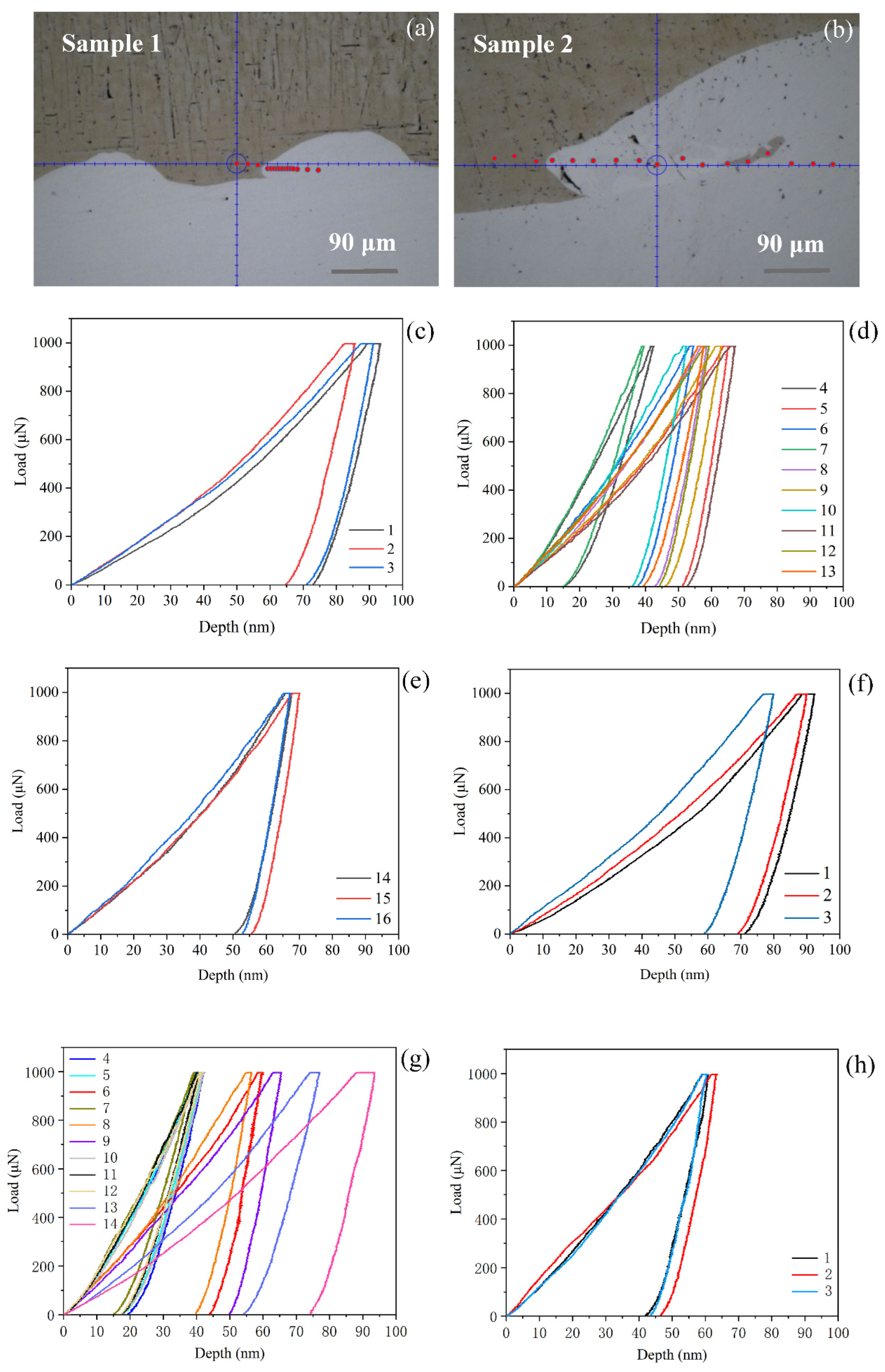
3.6. Nanoindentation

A nanoindentation experiment was performed to further understand the hardness change near the explosive welding interface [25,26]. The loading was 1000 μN. The test results are shown in Figure 10 and Table 2. In Sample 1, the interval in the titanium was approximately 15 um, the interval in the vortex area was approximately 5 um, and the interval in the duplex stainless steel was approximately 15 um. The dot order was from left to right. The interval in Sample 2 was approximately 15 μm. There were three test points in the titanium and duplex stainless steel, respectively. Little difference was observed between the hardness values of the titanium and duplex stainless steel in the two samples, while a large difference was observed in the hardness in the vortex region. The increase in the hardness in the vortex region of Sample 1 was caused by the large plastic deformation of the duplex stainless steel. Except for Nos. 4 and 7, the values of other points in the vortex region were slightly larger than those of the duplex stainless steel. The increase in hardness in the vortex region of Sample 2 was caused by large plastic deformation and generation of the alloy phase. The wide range of hardness changes in the vortex region was due to its complex composition [16]. The maximum hardness of the vortex region of the two samples was more than four times that of titanium and 2.5 times that of duplex stainless steel.

4. Conclusions

The mechanical properties of titanium/duplex stainless steel made by explosive cladding under two energy conditions were compared, and the conclusions are as follows:
  • DIC and 90° bending tests indicated that the interface with small waves had greater ability to resist plastic deformation. Overall, the mechanical properties of the small wavy interface were better.
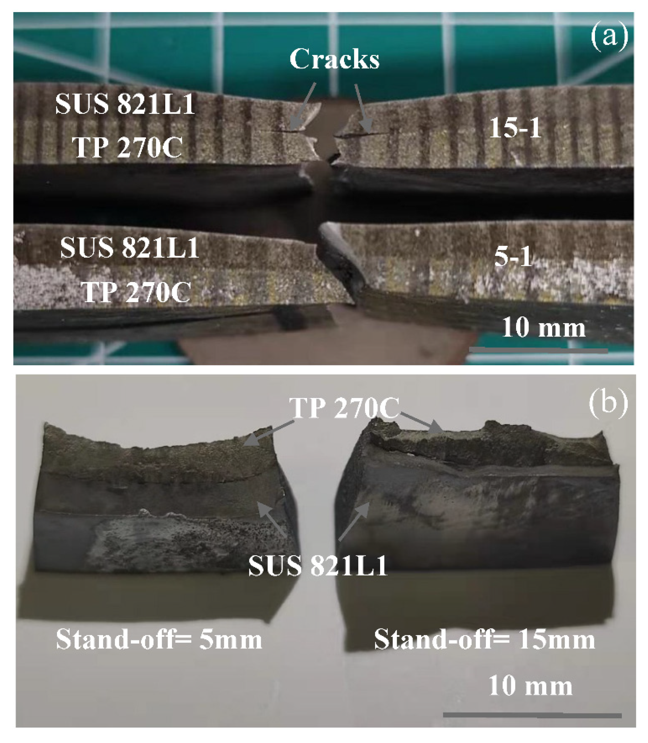
  • Little difference was found in the tensile properties of the composite plates obtained under the two welding energy conditions; the tensile stress of the large wavy interface was slightly higher. The crack propagation along the interface of the large waves after fracture was more obvious than that of the small wavy interface. The tensile fracture of pure titanium was ductile; however, the fracture of the titanium side was brittle in the composite plate.
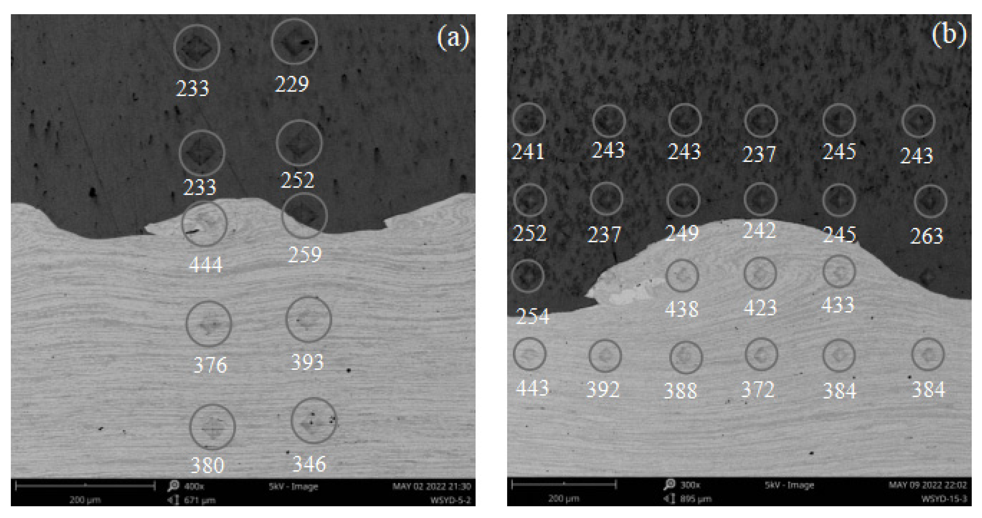
  • The hardness change near the interface was caused by large plastic deformation and alloy compounds. The hardness of the micro-area improved by only 1.5 times by large plastic deformation. Under the condition of high-energy welding, the hardness of the vortex region was complex due to the existence of many components and large plastic deformation.

Author Contributions

Conceptualization, X.C. and K.H.; methodology, K.W. and M.K.; software, S.N. and Y.W.; validation, X.L.; formal analysis, X.Z.; investigation, K.W.; resources, X.C.; data curation, X.Z.; writing—original draft preparation K.W.; writing—review and editing, X.C. and K.H.; supervision, X.L.; project administration, X.C.; funding acquisition, X.C. and X.L. All authors have read and agreed to the published version of the manuscript.

Funding

This research was funded by the projects of the State Key Laboratory of Precision Blasting and The National Science Foundation of China. The project numbers are 06070001, 06070002, and 12072067.

Institutional Review Board Statement

Not applicable.

Informed Consent Statement

Not applicable.

Data Availability Statement

Not applicable.

Conflicts of Interest

The authors declare no conflict of interest.

References

  1. Zhao, H.; Zhao, C.; Yang, Y.; Wang, Y.; Sheng, L.; Li, Y.; Huo, M.; Zhang, K.; Xing, L.; Zhang, G. Study on the Microstructure and Mechanical Properties of a Ti/Mg Alloy Clad Plate Produced by Explosive Welding. Metals 2022, 12, 399. [Google Scholar] [CrossRef]
  2. Parchuri, P.; Kotegawa, S.; Ito, K.; Yamamoto, H.; Mori, A.; Tanaka, S.; Hokamoto, K. Characterization of Shock Wave Damages in Explosion Welded Mo/Cu Clads. Metals 2021, 11, 501. [Google Scholar] [CrossRef]
  3. Mahmood, Y.; Dai, K.; Chen, P.; Zhou, Q.; Bhatti, A.A.; Arab, A. Experimental and Numerical Study on Microstructure and Mechanical Properties of Ti-6Al-4V/Al-1060 Explosive Welding. Metals 2019, 9, 1189. [Google Scholar] [CrossRef]
  4. Mousavi, S.A.; Sartangi, P.F. Experimental investigation of explosive welding of cp-titanium/AISI 304 stainless steel. Mater. Des. 2009, 30, 459–468. [Google Scholar] [CrossRef]
  5. Ribeiro, J.; Mendes, R.; Loureiro, A. Review of the weldability window concept and equations for explosive welding. J. Phys. Conf. Ser. 2014, 500, 052038. [Google Scholar] [CrossRef]
  6. Liu, Y.; Li, C.; Hu, X.; Yin, C.; Liu, T. Explosive Welding of Copper to High Nitrogen Austenitic Stainless Steel. Metals 2019, 9, 339. [Google Scholar] [CrossRef]
  7. Émurlaeva, Y.Y.; Bataev, I.A.; Zhou, Q.; Lazurenko, D.V.; Ivanov, I.V.; Riabinkina, P.A.; Tanaka, S.; Chen, P. Welding window: Comparison of deribas’ and wittman’s approaches and SPH simulation results. Metals 2019, 9, 1323. [Google Scholar] [CrossRef]
  8. Manikandan, P.; Hokamoto, K.; Deribas, A.A.; Raghukandan, K.; Tomoshige, R. Explosive Welding of Titanium/Stainless Steel by Controlling Energetic Conditions. Mater. Trans. 2006, 47, 2049–2055. [Google Scholar] [CrossRef]
  9. Manikandan, P.; Hokamoto, K.; Fujita, M.; Raghukandan, K.; Tomoshige, R. Control of energetic conditions by employing interlayer of different thickness for explosive welding of titanium/304 stainless steel. J. Mater. Process. Technol. 2008, 195, 232–240. [Google Scholar] [CrossRef]
  10. Habib, M.A.; Keno, H.; Uchida, R.; Mori, A.; Hokamoto, K. Cladding of titanium and magnesium alloy plates using energy-controlled underwater three layer explosive welding. J. Mater. Process. Technol. 2015, 217, 310–316. [Google Scholar] [CrossRef]
  11. Shi, C.; Yang, X.; Ge, Y.; You, J.; Hou, H. Lower limit law of welding windows for explosive welding of dissimilar metals. J. Iron Steel Res. Int. 2017, 24, 852–857. [Google Scholar] [CrossRef]
  12. Zhou, Q.; Feng, J.; Chen, P. Numerical and Experimental Studies on the Explosive Welding of Tungsten Foil to Copper. Materials 2017, 10, 984. [Google Scholar] [CrossRef]
  13. Carvalho, G.; Galvão, I.; Mendes, R.; Leal, R.M.; Loureiro, A. Weldability of aluminium-copper in explosive welding. Int. J. Adv. Manuf. Technol. 2019, 103, 3211–3221. [Google Scholar] [CrossRef]
  14. Chen, X.; Inao, D.; Tanaka, S.; Mori, A.; Li, X.; Hokamoto, K. Explosive welding of Al alloys and high strength duplex stainless steel by controlling energetic conditions. J. Manuf. Process. 2020, 58, 1318–1333. [Google Scholar] [CrossRef]
  15. Chen, X.; Li, X.; Inao, D.; Tanaka, S.; Hokamoto, K. Study of explosive welding of A6061/SUS821L1 using interlayers with different thicknesses and the air shockwave between plates. Int. J. Adv. Manuf. Technol. 2021, 116, 3779–3794. [Google Scholar] [CrossRef]
  16. Chen, X.; Inao, D.; Tanaka, S.; Li, X.-J.; Bataev, I.; Hokamoto, K. Comparison of explosive welding of pure titanium/SUS 304 austenitic stainless steel and pure titanium/SUS 821L1 duplex stainless steel. Trans. Nonferrous Met. Soc. China 2021, 31, 2687–2702. [Google Scholar] [CrossRef]
  17. Chen, X.; Inao, D.; Li, X.; Tanaka, S.; Li, K.; Hokamoto, K. Optimal parameters for the explosive welding of TP 270C pure titanium and SUS 821L1 duplex stainless steel. J. Mater. Res. Technol. 2022, 19, 4771–4786. [Google Scholar] [CrossRef]
  18. Miao, Y.; Chen, X.; Wang, H. Some applications of interlayer explosive welding. Compos. Interfaces 2021, 29, 345–360. [Google Scholar] [CrossRef]
  19. Paul, H.; Skuza, W.; Chulist, R.; Miszczyk, M.; Gałka, A.; Prażmowski, M.; Pstruś, J. The effect of interface morphology on the electro-mechanical properties of Ti/Cu clad composites produced by explosive welding. Metall. Mater. Trans. A 2020, 51, 750–766. [Google Scholar] [CrossRef]
  20. Pei, Y.; Huang, T.; Chen, F.; Pang, B.; Guo, J.; Xiang, N.; Song, Z.; Zhang, Y. Microstructure and fracture mechanism of Ti/Al layered composite fabricated by explosive welding. Vacuum 2020, 181, 109596. [Google Scholar] [CrossRef]
  21. Sun, W.; Guo, J.; Zhang, W.; Li, X.; Chen, X. Microstructure and Strengthening Mechanism of Ti/Cu Laminated Composite Produced by Underwater Explosive Welding. J. Mater. Eng. Perform. 2020, 29, 5069–5079. [Google Scholar] [CrossRef]
  22. Zeng, X.; Wang, Y.; Li, X.; Li, X.; Zhao, T. Effect of inert gas-shielding on the interface and mechanical properties of Mg/Al explosive welding composite plate. J. Manuf. Process. 2019, 45, 166–175. [Google Scholar] [CrossRef]
  23. Paul, H.; Chulist, R.; Mania, I. Structural Properties of Interfacial Layers in Tantalum to Stainless Steel Clad with Copper Interlayer Produced by Explosive Welding. Metals 2020, 10, 969. [Google Scholar] [CrossRef]
  24. Kaya, Y. Microstructural, Mechanical and Corrosion Investigations of Ship Steel-Aluminum Bimetal Composites Produced by Explosive Welding. Metals 2018, 8, 544. [Google Scholar] [CrossRef]
  25. Zhou, Q.; Liu, R.; Chen, P.; Zhu, L. Microstructure characterization and tensile shear failure mechanism of the bonding interface of explosively welded titanium-steel composite. Mater. Sci. Eng. A 2021, 820, 141559. [Google Scholar] [CrossRef]
  26. Yang, M.; Chen, D.; Zhou, H.; Xu, J.; Ma, H.; Shen, Z.; Zhang, B.; Tian, J. Experimental and numerical investigation of microstructure and evolution of TiNi Alloy/Q235 steel interfaces prepared by explosive welding. J. Mater. Res. Technol. 2021, 15, 5803–5813. [Google Scholar] [CrossRef]
Figure 1. Schematic of explosive welding. 1, flyer plate; 2, interface; 3, collided plate; 4, explosive; 5 jetting; 6, stand-off = 5 mm or 15 mm.
Metals 12 01354 g001
Figure 2. Welding interface: (a) stand-off = 5 mm; (b) stand-off = 15 mm.
Metals 12 01354 g002
Figure 3. Tensile curves.
Metals 12 01354 g003
Figure 4. DIC analysis: (a) test picture; (b) necking and strain distributions before cracking (stand-off = 15 mm, Ti side).
Metals 12 01354 g004
Figure 5. Samples after stretching.
Metals 12 01354 g005
Figure 6. Macro-fracture: (a) Side view; (b) Top view.
Metals 12 01354 g006
Figure 7. Fracture analysis: (a) TP 270C; (b) SUS 821L1; (c) weld seam, stand-off = 5 mm; (d) TP 270C side, stand-off = 5 mm, region I; (e) SUS 821L1 side, stand-off = 5 mm, region II; (f) weld seam, stand-off = 15 mm; (g) TP 270C side, stand-off = 15 mm, region III; (h) SUS 821L1 side, stand-off = 15 mm, region IV.
Metals 12 01354 g007aMetals 12 01354 g007b
Figure 8. Results of the 90° bending test: (a,b) macroscopic results; (c) before bending (stand-off = 5 mm); (d) after bending (stand-off = 5 mm); (e) before bending (stand-off = 15 mm); (f,g) after bending (stand-off = 15 mm).
Metals 12 01354 g008aMetals 12 01354 g008b
Figure 9. Vickers hardness test results: (a) stand-off = 5 mm; (b) stand-off = 15 mm.
Metals 12 01354 g009
Figure 10. Nanoindentation test results: (a) stand-off = 5 mm; (b) stand-off = 15 mm; (c) load displacement curve Nos. 1–3 in Sample 1; (d) load displacement curve Nos. 4–13 in Sample 1; (e) load displacement curve Nos. 14–16 in Sample 1; (f) load displacement curve Nos. 1–3 in Sample 2; (g) load displacement curve Nos. 4–14 in Sample 2; (h) load displacement curve Nos. 15–17 in Sample 1.
Metals 12 01354 g010
Table 1. Tensile strength of samples.
SampleTP 270CSUS 821L15-15-25-315-115-215-3
Yield strength (MPa)550520680670700710690705
Tensile strength (MPa)602729703688717747706713
Table 2. Nanoindentation hardness (Unit: GPa).
Sample 1
(Stand-off = 5 mm)
No.1No.2No.3No.4No.5No.6No.7No.8No.9
3.13.63.213.85.17.015.16.15.5
TiTiTiSUS 821L1SUS 821L1SUS 821L1SUS 821L1SUS 821L1SUS 821L1
No.10No.11No.12No.13No.14No.15No.16--
7.54.96.06.44.94.65.0--
SUS 821L1SUS 821L1SUS 821L1SUS 821L1Stainless steelSUS 821L1SUS 821L1--
Sample 2
(Stand-off = 5 mm)
No.1No.2No.3No.4No.5No.6No.7No.8No.9
3.13.34.012.413.55.915.56.45.1
TiTiTiAlloysAlloysAlloysAlloysAlloysAlloys
No.10No.11No.12No.13No.14No.15No.16No.17-
13.014.014.14.43.16.15.45.8-
AlloysAlloysAlloysTiTiSUS 821L1SUS 821L1SUS 821L1-
Publisher’s Note: MDPI stays neutral with regard to jurisdictional claims in published maps and institutional affiliations.

