Abstract
The carbon/carbon (C/C) composites and T2-copper were joined via thermo-compensated resistance brazing welding (RBW) with AgCuTi filler powder. The effects of the Ti content in AgCuTi filler powder on the interfacial microstructure and mechanical properties of resistance brazed joints were discussed in detail. The experiment results indicated that the interface structure of welded joints with composite filler metal was C/C composites/(TiC + TiCu) intermetallic compounds/Cu(s,s)/T2-copper. TiC and Ti-Cu were likely generated at the interface according to thermodynamics. When Ti content in the composite filler metal was 6 wt.%, the thickness of the reaction layer at the interface reached 4.2 μm, and the maximum shear strength of the joints reached 14.68 Mpa, which was the largest compared to other Ti contents. The EDS and XRD results of the fracture surfaces indicated that the TiCu and TiC IMCs were generated at the interface. Combined with the fracture morphologies, the fracture partially occurred in the TiC + TiCu layer, and partially occurred in the base metal of the C/C composites and the Cu alloy.
1. Introduction
Carbon/Carbon (C/C) composites have the feature of low density and a small coefficient of thermal expansion, and especially excellent mechanical properties at high temperature, which was supposed to be the alternative to other thermal structural materials and could be applied widely in the aerospace field [1,2,3,4]. T2-copper possesses excellent features such as electrical conductivity, thermal conductivity, and corrosion resistance, which also attracted widespread attention in the aerospace field [5,6,7]. The implementation of the C/C composites/T2-copper hybrid structure could integrate the characteristics of C/C composites and T2-copper, which improved the electrical conductivity effectively. Hence, it is necessary to achieve an effective connection between C/C composites and T2-copper by the appropriate welding method. Among a series of welding methods, brazing and diffusion welding attracted great attention from domestic and foreign scholars and they were extensively used in order to determine how to join C/C composites and other materials [8,9,10,11]. However, as we all know, there was poor wettability between the C/C composites and the T2-copper. It wasdifficult to obtain higher strength joints of the two materials directly. Ag-based filler metal, as an interlayer, also joined the C/C composites successfully and the high strength joint could finally be achieved. For example, C/C composites and copper were successfully joined with AgCuTi filler metal by vacuum brazing [ 12]. Moreover, Zhou et al. [13] achieved the joining between C/C composites and TC4 alloy using nano-Al2O3 strengthened AgCuTi composite filler via vacuum brazing and the effect of the temperature and addition of nano-Al2O3 on the brazed joint was investigated. Guo et al. [14] joined the C/C composites to TC4 alloy with the AgCu foil as the filler metal by vacuum brazing and the microstructure and bonding of the brazed joint were discussed. Liu et al. [15] realized that the brazing joining between C/C composites and the TC4 alloy using the graphene nanosheets reinforced AgCuTi composite filler metal, and the maximum shear strength of the brazed joint was about 23.3 MPa. Zhang et al. [16] utilized diamond particle strengthened Ag-Cu-Ti brazing alloy joining C/C composites to stainless steel and the effects of the volume percentage of diamond particles on the brazed joints were studied. Furthermore, the relevant research verified that Ti, as the filler metal, reacted with the C/C composite matrix and other materials to form a robust bonding [17,18].
The above-mentioned methods could better achieve C/C composites and metals, but some necessary conditions were essential such as a long welding time, a high welding temperature, and even additional welding pressure, which greatly reduced welding efficiency. Hence, developing a fast and effective joining method was significant in joining C/C composites and other metals. Resistance spot welding, a welding method joining welding materials through welding pressure, large welding current, and short welding cycle time, was widely used. For example, the maximum tensile-shear strength of dissimilar DP600 and DC54D steels was obtained under 14 cycles of welding time by Yuan et al. [19]. However, due to the direct contact of dissimilar materials in the traditional resistance spot welding process, the welding defects such as cracks and pores, and the brittle intermetallic compounds were produced at the welded joints because of the differences in physical-chemical properties between materials, which was detrimental to the mechanical properties of the joints [20]. The high-quality welded joint could be obtained by resistance brazing welding, which relies on the melted filler material at the interface only. Meanwhile, the method also integrated the high-efficiency characteristics of traditional resistance spot welding, which is a significant joining method in the automotive industry [21,22]. Zhang et al. [23] studied the microstructure and interfacial reaction of the Ti/steel welded joints by the resistance brazing method and indicated that the filler materials had a significant effect on the microstructure of the resistance brazed joint. The interfacial metallurgical behavior was changed and the generation of brittle Ti-Fe intermetallic compounds was inhibited effectively, which improved the mechanical properties of the welded joints. Vodă et al. [24] presented resistance brazing stainless steels with Ni-based amorphous alloys as the filler metal and indicated that the required temperature for the resistance brazing process was lower than that of the resistance spot welding with the advantage of avoiding structural changes in the parent material.
Hence, C/C composites and T2-copper were joined by resistance brazing welding (RBW) using the AgCuTi powder with different Ti contents. The effect of Ti contents in the filler metal on the interfacial microstructure and mechanical properties of the welded joints were discussed in detail.
2. Experiment
2.1. Materials
C/C composites with the dimension of 9 mm × 9 mm × 8 mm and T2-copper with the dimension of 18 mm × 18 mm × 2.5 mm were employed in this experiment by wire cutting. Before the formal experiment, C/C composites and the T2-copper were ground by 400, 600, 800 and 1000 grit silicon carbide paper in turn and then cleaned ultrasonically in acetone for 10 min. Subsequently, these welded samples were dried by the blower. Then these specimens were cleaned with acetone and alcohol again. The microstructures of the pretreatment C/C composites and Cu alloy are depicted in Figure 1a,b, respectively. Ag-26.7Cu-4.5Ti (wt.%) powder with a particle size of 200 mesh and Ti powder (≤99.5 wt%) with a particle size of 300 mesh were chosen as filler metal to join copper and C/C composites, respectively. Ti powder was obtained by the hydrogen-dehydrogenation method. Table 1 listed the chemical composition of the Ti powder. Based on the relevant research [25,26,27] and the prior experiment results, Ti powder was added to AgCuTi powder and the composite fillers were milled by the QM-SB planetary ball mill (Changsha Tianchuang Powder Technology Co., Ltd., Changsha, China) with six hours. The Ti content in the composite fillers was 6, 7.5 and 9% (wt.%), respectively. The XRD patterns of AgCuTi composites filler metal with different Ti contents (illustrated in Figure 2) could prove whether the metallurgical reactions occurred during the ball milling process. The peaks of Ag, Cu, and Ti only were detected, which indicated that no metallurgical reaction occurred in the ball milling process.
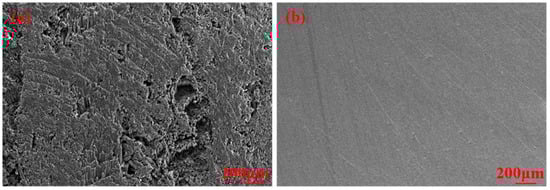
Figure 1.
Microstructures of the base metal: (a) C/C composites, (b) Cu alloy.

Table 1.
Chemical composition of Ti powder (≤wt.%).
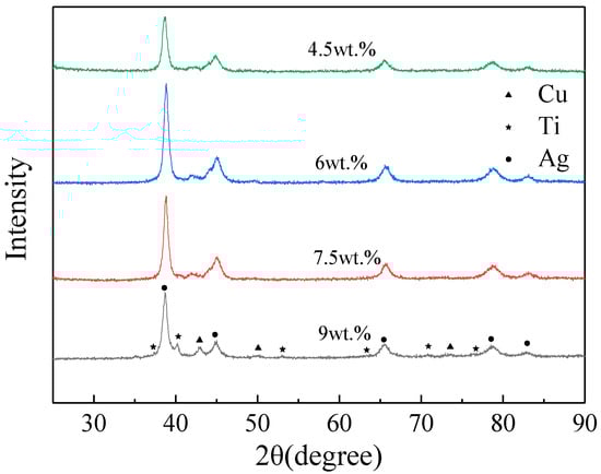
Figure 2.
XRD patterns of AgCuTi composite filler with different Ti contents.
2.2. Equipment
The actual image and schematic diagram of the welding process of thermo-compensated resistance brazing welding joining C/C composites and T2 copper is shown in Figure 3a,b. Figure 3c shows that the filler metal was embedded between the sample of C/C composites and the T2 copper. Besides, the generated heat in both the upper electrode and the lower electrode was low, which meant that it was difficult to achieve the ideal and stable welding process by depending on this heat only. A cylindrical graphite block with the dimensions of φ20 × 10 mm was applied as the conductive electrode due to its high resistivity characteristics, and this was placed in the middle of the upper electrode and T2-copper in the welding process, which is known as a thermo-compensated RBW process. Hence, it was considered that resistance heat was mainly produced by graphite and C/C composites. The heat was calculated as follows:
where Q, I, R, t, ρ, L and S were the heat, welding current, resistance, time, resistivity, the length of resistance, and the cross-section of resistance, respectively.
Q = I2·R·t
R = ρ L/S,
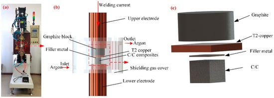
Figure 3.
(a)The actual image of the RBW welding process, Schematic diagram of (b) the welding process, and (c) the welding specimens.
Based on the aforementioned formulas, the characteristics and properties of the materials directly affected the amount of resistance. Therefore, the shape and size of the electrodes and welding materials should be equal throughout the whole experiment. To ensure the constant resistance as much as possible, the upper electrode and the lower electrode were also ground by 400, 600, 800 and 1000 grit silicon carbide paper in turn and then cleaned ultrasonically in acetone for 10 min. Subsequently, these welded samples were also dried by the blower, then cleaned with acetone and alcohol again. Based on the schematic diagram of the RBW welding process in Figure 3b, after all the samples were assembled in the upper and lower electrodes, pure argon (≥99.99%) as shielding gas was protected during the entire welding process. Because of the oxidizability of welding materials, shielding gas was immediately injected into the cover in the pre-welding preparation. Furthermore, shielding gas was stopped to inject the whole welding process until the welding specimens were cooled to room temperature. Meanwhile, the RBW process was achieved by the DB-165 direct resistance spot welding machine.
2.3. Microstructural Analysis and Shear Strength Test
The microstructural samples were also sectioned perpendicular to the welding surface via wire cutting. The microstructures, elemental distributions, and fracture morphology of the welding specimens were analyzed and identified via a scanning electron microscope (SEM, MERLIN Compact, ZEISS, Stuttgart, Germany) equipped with an energy-dispersive X-ray spectrometer (EDS, OCTANE PLUS, EDAX, Mahwah, NJ, USA). The generated intermetallic compounds of the fracture surface were confirmed by X-ray diffraction (XRD, DX-2700,Dandong Haoyuan Instrument Co., Ltd., Dandong, China). The surface temperature at the interface was obtained by an infrared thermal imaging camera (FLIR A315, FLIR, Wilsonville, OR, USA). The schematic diagram of the compressive shear test setup was shown in Figure 4. Shear strength was tested by a universal strength testing machine (Instron 5967, Instron, Boston, MA, USA) with a constant speed of 0.5 mm/min at room temperature. Furthermore, at least three complete shear samples were tested for every welding parameter and the average value of all samples was obtained as the final result of shear strength.
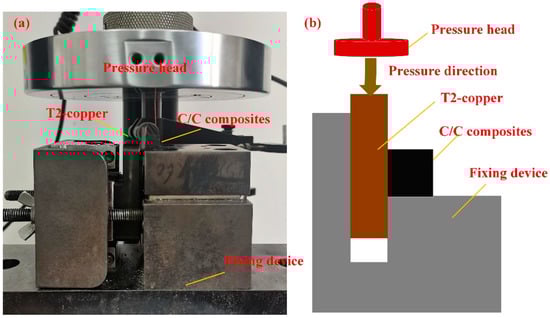
Figure 4.
(a)The actual image of the shear test setup, (b) Schematic diagram of the shear test setup.
3. Results and Discussion
3.1. The Effect of Ti Content in the Composite Filler Metal on the Joint
The optimal welding parameters are listed in Table 2 based on the preliminary orthogonal experiment, and the welding current with five pulses was utilized in the welding process. The following experiments were carried out under this parameter.
Table 2.
Optimal welding parameters.
The macroscopic joints of the composite filler metal with different Ti contents via RBW are shown in Figure 5. When the Ti content was 4.5 wt.% and 6 wt.%, respectively, the melted filler metal was extruded under the action of welding pressure and there was no obvious defect in the joints. Because the resistivity of Ti was more than Ag and Cu, the generated heat was improved with the increase of Ti content if the welding current was all the same according to Equations (1) and (2). When the Ti content was 7.5 wt.%, the generated heat and melted metal were improved further, which caused the spillage of filler metal under the action of welding pressure as shown in Figure 5c. However, when the Ti content was raised to 9 wt.%, the generated heat and melted metal were increased greatly, which means that the C/C composites were pressed into the T2-copper under the action of pressure and then a few spatters were generated, as shown in Figure 5d,e. Furthermore, large holes were found on the back surface at this Ti content, as shown in Figure 5f. The reason may be that the spattered Cu couldn’t be replenished in the cooling process, so it formed the shrinkage cavity in the slowest cooling location from the center of the back weldment.
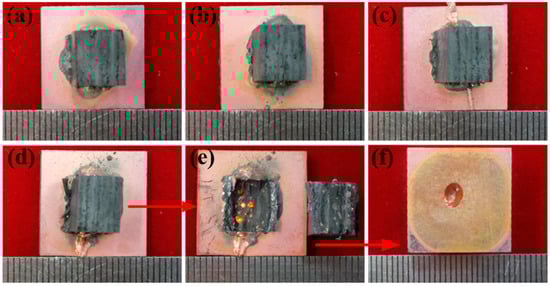
Figure 5.
Schematic diagram of macroscopic joint forming of composite filler metal with different Ti contents at the optimal parameter. (a) 4.5 wt.%, (b) 6 wt.%, (c) 7.5 wt.%, and (d) 9 wt.% with fracture morphology (e) and back-welding shape (f).
The strength-displacement curves of the welded joints with composite filler metal with different Ti contents are shown in Figure 6a–d. Figure 6e depicts the variation of the average shear strength of joints with different Ti contents. As shown in Figure 6e, the shear strength of joints first increased and then decreased with the increase of the Ti content. When the Ti content in filler metal was 6 wt.%, the shear strength of the joint was the largest and reached 14.68 MPa. As Ti content continued to increase, the shear strength gradually decreased, which was attributed to the interface structure. In addition, when the Ti content in the filler metal increased to 9 wt.%, the shear strength of the joint was still very high, and this is attributed to the C/C composites pressing into the T2-copper. Therefore, SEM and EDS analyses were achieved only in the other three Ti contents due to this problem.
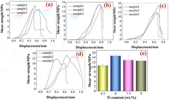
Figure 6.
Schematic diagram of shear strength with different Ti contents: The strength-displacement curves of the welded joints with (a) 4.5 wt.% Ti, (b) 6 wt.% Ti, (c) 7.5 wt.% Ti, (d) 9 wt.% Ti, and (e) the comparison results of the average strength.
Figure 7a depicts the interface structure between C/C composites and T2 copper via composite filler metal with 4.5 wt.% Ti by RBW. Figure 7b shows the corresponding element mapping image in Figure 7a. As shown in Figure 7b, there was a thinner reaction layer at the interface and only 3% of the Ti elements were detected at the interface. The result of the EDS line-scan in the red line in Figure 7a is depicted in Figure 8. Less Ti element was located at the interface and formed TiC with C element due to the strong affinity, as shown in Figure 8. Meanwhile, the diffusion layer between C and Cu elements was generated at the interface in Figure 8, which mainly determined the mechanical properties of the welded joints. The composition and thickness of the interfacial reaction layer had a significant effect on the mechanical properties of dissimilar materials joints [28,29,30,31]. Therefore, the joint strength was the lowest when the Ti content in the filler metal was 4.5 wt.%. Figure 9a,b shows the interface structure between C/C composites and the T2 copper via composite filler metal with 6 wt.% Ti and 7.5 wt.% Ti, respectively. As shown in Figure 9a,b, there was an obvious separate reaction layer when the Ti content was 6 wt.% and 7.5 wt.%. The EDS analysis results of each spot marked in Figure 9 are shown in Table 3. It was inferred that the TiC and TiCu IMCs were formed at the interface reaction layers. The EDS results on element distribution along the red lines indicated in Figure 9 are shown in Figure 10. The element distribution in Figure 10 indicated element aggregation at the interface. It was again proved that the reaction layer has Cu(s,s), TiCu, and TiC IMCs. According to the element distribution, the possibility of generating Cu(s,s), TiCu, and TiC IMCs in the reaction layer was again demonstrated in terms of atomic ratios. Therefore, it was inferred that the interfacial structure was mainly C/C composites/TiC + TiCu IMCs/Cu (s,s)/T2-copper when Ti contents were 6 wt.% and 7.5 wt.% Ti. However, the thickness of the reaction layer was 4.2 μm when the Ti content was 6 wt.% in the filler metal. This proved the filler metal with 6 wt.% Ti formed a better joining between C/C composites and copper, improving the strength of the welded joints. When the Ti content was 7.5 wt.% in the filler metal, the thickness of the reaction layer was only about 1.2 μm. Consistent with Figure 5, with the increase of Ti content, the increase of the generated resistant heat led to the overflow of the melted filler metal at the interface under the same welding parameters. Therefore, the thickness of the interface reaction layer decreased, reducing the strength of the welded joints.
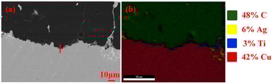
Figure 7.
(a) the interfacial structure of the welded joints with 4.5 wt.% Ti, (b) the relevant element mapping image in (a).
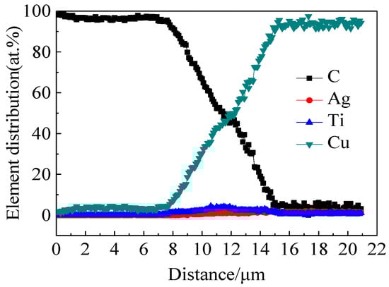
Figure 8.
The results of the EDS line-scan in the red line in Figure 7a.
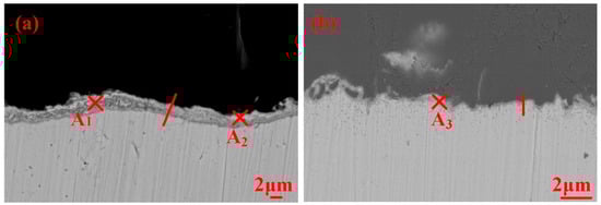
Figure 9.
The interfacial structure of different Ti contents at the optimal parameters. (a) 6 wt.%, (b) 7.5 wt.%.
Table 3.
EDS results of marked points in Figure 9 (at.%).
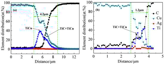
Figure 10.
The results of EDS line-scan in the interlayer of welded joint with different Ti contents. (a) 6 wt.%, (b) 7.5 wt.%.
The fracture surfaces of the resistance brazed joint of 6 wt.% Ti content with C/C composite side and Cu side are depicted in Figure 11a,d, respectively. To investigate the fracture mechanism, the magnified images of A, B, C, and D areas are shown in Figure 11b,c,e,f, respectively. The relevant EDS results of points (1–11) denoted in Figure 11 are illustrated in Table 4. C, Cu(s,s), TiC and TiCu IMCs were generated at the fracture surface coupled with the EDS results, as shown in Table 4. Meanwhile, combined with the fracture morphology, it was concluded that the melted filler metal formed a good bond with a part of the base metal of C/C composites and Cu alloy under the action of resistance heat. Hence, the fracture partially occurred in the TiC + TiCu layer, and also partially occurred in the base metal of C/C composites and the Cu alloy. Figure 12a,b indicates that the XRD results from the fracture surface with the welded joint of 6 wt.% Ti content with the C/C side and Cu side, respectively. The TiCu and TiC IMCs were also detected at the interface, which was consistent with that of the aforementioned EDS results.
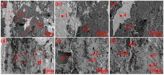
Figure 11.
The fracture surfaces with the welded joints: (a) C/C composites side, (b) the magnified image of A area, (c) the magnified image of B area, (d) Cu side, (e) the magnified image of C area, (f) the magnified image of D area.
Table 4.
EDS results of marked points in Figure 11 (at.%).
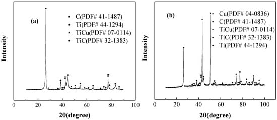
Figure 12.
XRD results of the fracture surface of the welded joints: (a) C/C side, (b) Cu side.
Figure 13 depicts the interface temperature between C/C composites and T2-copper with the second section of welding parameters in Table 2 measured by the infrared thermal imaging camera. It was found that the initial temperature of the surface temperature at the interface between C/C composites and T2-copper reached 180 °C. This was attributed to the resistance heat generated in the first stage with the welding parameters (welding current of 5 kA, welding time of 30 ms, and welding pressure of 0.01 MPa). Meanwhile, filler metal at the interface would be softened and the tiny plastic deformation therefore occurred under the function of temperature and pressure. As a result, the contact area between the filler metal and base metal on both sides was increased, and then the resistance at the interface was decreased according to Equation (2), which provided a condition and preparation for the second section of welding parameters to heat the filler metal. Subsequently, the maximum temperature of the surface increased to 948.9 °C in the second stage, as shown in Figure 13b. Generally, the welding nugget was generated inside the workpiece due to the instantaneous resistance heat in the traditional resistance welding process, meaning that the internal temperature of the workpiece was higher than the surface temperature. Therefore, the internal temperature of the workpiece may reach the melting point of the Cu parent metal in this method. Hence, as the temperature increased, the degree of Cu element from Cu parent metal diffusion to the interface increased, resulting in the increase of the content of Cu at the interface in Table 3 and Table 4, too.
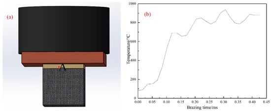
Figure 13.
The temperature measurement at the interface of the joint. (a) schematic diagram of equipment, (b) temperature variation curve of point A at the interface.
3.2. Thermodynamic Analysis and Microstructure Evolution of the Welded Joint
Above all, TiC and TiCu IMCs were generated at the interface between C/C composites and Cu alloy. The Gibbs free energy of TiC, TiCu, and Ti2Cu are presented in Equations (3)–(5) as follows [16,32,33]:
C + Ti → TiC, ∆G1 = −183.1 + 0.01 T (kJ/mol)
Ti + Cu → TiCu, ∆G2 = −17,069 + 4.887 T (J/mol)
Ti + 1/2Cu → 1/2Ti2Cu, ∆G3 = −17,130 + 5.708 T (J/mol)
From the standpoint of thermodynamics, the obtained largest Gibbs free energy (∆G1, ∆G2, ∆G3) from the forming of TiC, TiCu, Ti2Cu calculated by Equations (3)–(5) was less than zero and negative for temperatures from 900 °C to 1500 °C. Therefore, the reactions of Equations (3)–(5) must occur spontaneously in the welding process. The actual interfacial maximum temperature in the welding process was located in this region based on the maximum temperature of the surface. Assuming the maximum temperature reached 1200 °C, the Gibbs free energy is all negative, and the Gibbs free energy (∆G1, ∆G2, ∆G3) from forming TiC, TiCu, Ti2Cu calculated by Equations (3)–(5) was −168,370 J/mol, −9870.449 J/mol, −8722.116 J/mol. Compared to ∆G2 and ∆G3, there was a lower Gibbs free energy of TiCu than Ti2Cu. Hence, the TiCu phase was generated earlier than the Ti2Cu phase at the interface. This further proved that TiC and TiCu IMCs could be generated at the interface, which was consistent with the abovementioned results.
The actual RBW welding process contained three stages with individual welding parameters. Therefore, the bonding process of welded joints could be divided into three stages according to three sections of welding parameters, as shown in Figure 14. Figure 14a depicts the original interface of the welded joints before the formal welding. Consistent with Figure 13b, the temperature was formed at the interface with the first welding process. The results were that the filler metal at the interface would be softened and the tiny plastic deformation occurred under the function of temperature and pressure. Meanwhile, elements diffused to a certain extent at the interface under the action of temperature in Figure 14a. Under the action of the second section of welding parameters in Table 2, a lot of resistance heat was produced at the interface between the C/C composites and T2-copper. Based on the temperature in Figure 13b, the generated heat might havenot only melted the filler powder but also the T2-copper, which integrated the filler metal with T2-copper effectively. Moreover, the degree of element diffusion at the interface increased, as shown in Figure 14c. The result was that the Cu content in the molten filler metal was increased markedly. Under the action of the third section of the welding parameter (welding current of 5 kA, welding time of 30 ms, and welding pressure of 0.01 MPa), the welding process could be kept at a high temperature for a period of time. Therefore, the molten filler metal had a long time to diffuse and react with the base metal. Figure 14d depicts the forming process of the reaction layer and atomic diffusion at a high temperature. As shown in Figure 14d, the activity of C was activated at the high temperature, then diffused to filler metal under the action of driving force due to the concentration gradient of the solid-liquid interface on both sides. Furthermore, there was a great appeal between C and Ti [34], meaning that Ti from the molten filler metal was spread and generated rapidly in the direction of the C/C composites. TiC was generated on the side of C/C composites according to the Gibbs free energy of the reaction between Ti and C. Meanwhile, the Cu content in the molten filler metal was increased signally due to the diffusion of the Cu element from the Cu parent metal, which could inhibit the activity of Ti [35]. As a result, the reaction between Ti and C can’t be carried out quickly. and Cu also reacted with a large amount of Ti on the side of C/C composites to generate TiCu IMC. Therefore, the composite reaction layer of TiC and TiCu IMC was formed at the interface.
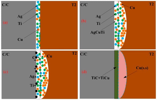
Figure 14.
Schematic diagram of interface evolution model. (a) the interface before the formal welding, (b) the interface during welding, (c) atomic diffusion at the interface, and (d) the ultimate reaction layer at the interface.
4. Conclusions
The interface structure and mechanical properties of the welded joints between C/C composites and T2-copper via the thermo-compensated RBW were studied in this paper and the relevant conclusions were drawn as follows. It was inferred that the interface structure of welded joints with different Ti contents in the composite filler metal was C/C composites/TiC + TiCu IMC/Cu (s,s)/T2-copper. TiC and TiCu IMC were likely generated according to thermodynamics. When the Ti content was 6 wt.%, the obtained welded joints were formed well and the thickness of the reaction layer at the interface reached 4.2 μm, which was the largest compared to other Ti contents. Meanwhile, the joint performance with 6 wt.% Ti was the best in this parameter, and the maximum shear strength of the welded joints reached 14.68 MPa. The fracture morphologies indicated that the TiCu and TiC IMCs were generated at the interface based on the EDS results. The XRD results of fracture surface with the welded joint of 6 wt.% Ti content also detected TiCu and TiC IMCs at the interface. Hence, the fracture partially occurred in the TiC + TiCu layer and partially occurred in the base metal of C/C composites and Cu alloy combined with the fracture morphologies.
Author Contributions
Conceptualization, J.Y. and X.M.; Investigation, X.M., H.Z. and C.Q.; data curation, X.M., B.W. and C.Q.; formal analysis, X.M. and C.Q.; writing—original draft preparation, J.Y. and B.W.; writing—review and editing, H.Z. and C.Q.; funding acquisition, H.Z.; project administration, H.Z. All authors have read and agreed to the published version of the manuscript.
Funding
This research was funded by National Natural Science Foundation of China (52175305).
Institutional Review Board Statement
Not applicable.
Informed Consent Statement
Not applicable.
Data Availability Statement
If readers are interested in the data, please contact the corresponding author for the complete dataset.
Acknowledgments
The work was financially supported by National Natural Science Foundation of China (52175305), Young Taishan Scholars Program of Shandong Province (tsqn20161062), Natural Science Foundation of Shandong Province (ZR2019PEE010), Major scientific and technological innovation projects in Shandong Province (2019JZZY010366), and the central government of Shandong province guide local science and technology development fund project (YDZX20203700003578).
Conflicts of Interest
The authors declare that they have no conflict of interest.
References
- Huo, C.; Guo, L.; Cao, A.; Wang, Z.; Wang, C.; Kou, G.; Zhang, Y. The Degradation Behavior of C/C Composites in High-Energy Atomic Oxygen. Vacuum 2017, 146, 120–129. [Google Scholar] [CrossRef]
- Yi, Z.; Ran, L.; Yi, M. Differences in Microstructure and Properties of C/C Composites Brazed with Ag-Cu-Ti and Ni-Cr-P-Ti Pasty Brazing Filler. Vacuum 2019, 168, 108804. [Google Scholar] [CrossRef]
- Zhang, G.; Zhang, Y.; Bao, J.; Yang, G. A Novel Active Braze Composition Design Route for C/C Composite Using Fe as Active Element. Carbon 2021, 181, 177–192. [Google Scholar] [CrossRef]
- Shokati, A.A.; Zhou, N.Y.; Wen, J.Z. Dissimilar Joining of Carbon/Carbon Composites to Ti6Al4V Using Reactive Resistance Spot Welding. J. Alloys Compd. 2019, 772, 418–428. [Google Scholar] [CrossRef]
- Dhara, S.; Das, A. Impact of Ultrasonic Welding on Multi-Layered Al–Cu Joint for Electric Vehicle Battery Applications: A Layer-Wise Microstructural Analysis. Mater. Sci. Eng. A 2020, 791, 139795. [Google Scholar] [CrossRef]
- Fujii, H.T.; Endo, H.; Sato, Y.S.; Kokawa, H. Interfacial Microstructure Evolution and Weld Formation during Ultrasonic Welding of Al Alloy to Cu. Mater. Charact. 2018, 139, 233–240. [Google Scholar] [CrossRef]
- Zhang, L.J.; Zhang, G.F.; Ning, J.; Zhang, X.J.; Zhang, J.X. Microstructure and Properties of the Laser Butt Welded 1.5-Mm Thick T2 Copper Joint Achieved at High Welding Speed. Mater. Des. 2015, 88, 720–736. [Google Scholar] [CrossRef]
- Wang, Z.; Wang, G.; Li, M.; Lin, J.; Ma, Q.; Zhang, A.; Zhong, Z.; Qi, J.; Feng, J. Three-Dimensional Graphene-Reinforced Cu Foam Interlayer for Brazing C/C Composites and Nb. Carbon 2017, 118, 723–730. [Google Scholar] [CrossRef]
- Luo, Y.; Bian, H.; Niu, H.W.; Song, Y.Y.; Chen, Z.B.; Song, X.G.; Wang, M.R. Interfacial Microstructure and Mechanical Properties of C/C Composites and Nb Joints Brazed with Cu75Pt25 Filler Metal. Vacuum 2018, 157, 202–209. [Google Scholar] [CrossRef]
- Shi, X.; Jin, X.; Lin, H.; Jing, J.; Li, L.; Wang, C. Joining of SiC Nanowires-Toughened SiC Coated C/C Composites and Nickel Based Superalloy (GH3044) Using Ni71CrSi Interlayer. J. Alloys Compd. 2017, 693, 837–842. [Google Scholar] [CrossRef]
- Huang, D.; Zhang, M.; Huang, Q.; Wang, L.; Tong, K. Mechanical Property, Oxidation and Ablation Resistance of C/C–ZrB2–ZrC–SiC Composite Fabricated by Polymer Infiltration and Pyrolysis with Preform of Cf/ZrB2. J. Mater. Sci. Technol. 2017, 33, 481–486. [Google Scholar] [CrossRef]
- Zhang, K.; Xia, L.; Zhang, F.; He, L. Active Brazing of C/C Composite to Copper by AgCuTi Filler Metal. Metall. Mater. Trans. A Phys. Metall. Mater. Sci. 2016, 47, 2162–2176. [Google Scholar] [CrossRef]
- Zhou, Y.H.; Liu, D.; Niu, H.W.; Song, X.G.; Yang, X.D.; Feng, J.C. Vacuum Brazing of C/C Composite to TC4 Alloy Using Nano-Al2O3 Strengthened AgCuTi Composite Filler. Mater. Des. 2016, 93, 347–356. [Google Scholar] [CrossRef]
- Guo, W.; Wang, L.; Zhu, Y.; Chu, P.K. Microstructure and Mechanical Properties of C/C Composite/TC4 Joint with Inactive AgCu Filler Metal. Ceram. Int. 2015, 41, 7021–7027. [Google Scholar] [CrossRef]
- Liu, D.; Song, Y.; Zhou, Y.; Song, X.; Fu, W.; Feng, J. Brazing of C/C Composite and Ti-6Al-4V with Graphene Strengthened AgCuTi Filler: Effects of Graphene on Wettability, Microstructure and Mechanical Properties. Chin. J. Aeronaut. 2018, 31, 1602–1608. [Google Scholar] [CrossRef]
- Zhang, S.; Yuan, Y.; Su, Y.; Song, X. Interfacial Microstructure and Mechanical Properties of Brazing Carbon/Carbon Composites to Stainless Steel Using Diamond Particles Reinforced Ag-Cu-Ti Brazing Alloy. J. Alloys Compd. 2017, 719, 108–115. [Google Scholar] [CrossRef]
- Wang, J.; Kezhi, L.I.; Song, X.; Guo, L.; Wei, L.I.; Zhaoqian, L.I. The Study on Joining Carbon/Carbon Composites Using Ti―Ni―Si Compound. Mater. Sci. Eng. A 2012, 547, 12–18. [Google Scholar] [CrossRef]
- Ikesheoji, T.-T.; Amanuma, T.; Suzumura, A.; Yamazaki, T. Shear Strength of Brazed Joint Between Titanium and C/C Composites With Various Cross-Ply Angles. J. Solid Mech. Mater. Eng. 2011, 5, 1022–1028. [Google Scholar] [CrossRef][Green Version]
- Yuan, X.; Li, C.; Chen, J.; Li, X.; Liang, X.; Pan, X. Resistance Spot Welding of Dissimilar DP600 and DC54D Steels. J. Mater. Process. Technol. 2017, 239, 31–41. [Google Scholar] [CrossRef]
- Yu, J.; Zhang, H.; Wang, B.; Gao, C.; Sun, Z.; He, P. Dissimilar Metal Joining of Q235 Mild Steel to Ti6Al4V via Resistance Spot Welding with Ni–Cu Interlayer. J. Mater. Res. Technol. 2021, 15, 4086–4101. [Google Scholar] [CrossRef]
- Tahri, C.; Bertoni, C.; Feulvarch, E.; Klocker, H.; Bergheau, J.M. Numerical Simulation of the Resistance Braze Welded Assembly of a Copper Inconel 601 Ground Electrode and a Steel Shell. Numer. Heat Transf. Part A Appl. 2020, 78, 73–93. [Google Scholar] [CrossRef]
- Ji, H.; Li, M.; Lu, Y.; Wang, C. Mechanical Properties and Microstructures of Hybrid Ultrasonic Resistance Brazing of WC-Co/BeCu. J. Mater. Process. Technol. 2012, 212, 1885–1891. [Google Scholar] [CrossRef]
- Zhang, P.; Fang, Z.; Li, S. Microstructure and Interfacial Reactions of Resistance Brazed Lap Joints between Tc4 Titanium Alloy and 304 Stainless Steel Using Metal Powder Interlayers. Materials 2021, 14, 180. [Google Scholar] [CrossRef] [PubMed]
- Vodă, M.; Codrean, C.; Chicot, D.; Şerban, V.A.; Uţu, D.; Linul, E.; Buzdugan, D. Characterization of Brazed Joints by Electrical Resistance Spot Brazing with Ni-Based Amorphous Self-Flux Alloys. J. Manuf. Process. 2019, 37, 617–627. [Google Scholar] [CrossRef]
- Zhao, Y.X.; Song, X.G.; Tan, C.W.; Hu, S.P.; Cao, J.; Feng, J.C. Microstructural Evolution of Si3N4/Ti6Al4V Joints Brazed with Nano-Si3N4 Reinforced AgCuTi Composite Filler. Vacuum 2017, 142, 58–65. [Google Scholar] [CrossRef]
- Song, Y.; Liu, D.; Hu, S.; Song, X.; Cao, J. Graphene Nanoplatelets Reinforced AgCuTi Composite Filler for Brazing SiC Ceramic. J. Eur. Ceram. Soc. 2019, 39, 696–704. [Google Scholar] [CrossRef]
- Song, X.; Zhao, Y.; Hu, S.; Cao, J.; Fu, W.; Feng, J. Wetting of AgCu-Ti Filler on Porous Si3N4 Ceramic and Brazing of the Ceramic to TiAl Alloy. Ceram. Int. 2018, 44, 4622–4629. [Google Scholar] [CrossRef]
- Zhu, W.; Chen, J.; Jiang, C.; Hao, C.; Zhang, J. Effects of Ti Thickness on Microstructure and Mechanical Properties of Alumina-Kovar Joints Brazed with Ag-Pd/Ti Filler. Ceram. Int. 2014, 40, 5699–5705. [Google Scholar] [CrossRef]
- Jin, Y.; Jiahao, S.; Chenkai, G.; Yixuan, Z.; Hongbing, L.; Ovliera, J.P.; Caiwang, T.; Zhishui, Y. Effect of Heat Input on Interfacial Microstructure, Tensile and Bending Properties of Dissimilar Al/Steel Lap Joints by Laser Welding-Brazing. Opt. Laser Technol. 2021, 142, 107218. [Google Scholar] [CrossRef]
- Shamsolhodaei, A.; Oliveira, J.P.; Schell, N.; Maawad, E.; Panton, B.; Zhou, Y.N. Controlling Intermetallic Compounds Formation during Laser Welding of NiTi to 316L Stainless Steel. Intermetallics 2020, 116, 106656. [Google Scholar] [CrossRef]
- Oliveira, J.P.; Shen, J.; Zeng, Z.; Park, J.M.; Choi, Y.T.; Schell, N.; Maawad, E.; Zhou, N.; Kim, H.S. Dissimilar Laser Welding of a CoCrFeMnNi High Entropy Alloy to 316 Stainless Steel. Scr. Mater. 2022, 206, 114219. [Google Scholar] [CrossRef]
- Wang, W.; Liu, Y.; Wang, G.; Tan, C.; Cao, W. Vacuum Brazing ZSCfcomposite Ceramics to TC4 Alloy with Ag-Cu Filler. J. Mater. Res. Technol. 2020, 9, 8627–8635. [Google Scholar] [CrossRef]
- Liu, Y.; Wang, G.; Cao, W.; Xu, H.; Huang, Z.; Zhu, D.; Tan, C. Brazing ZrB2-SiC Ceramics to Ti6Al4V Alloy with TiCu-Based Amorphous Filler. J. Manuf. Process. 2017, 30, 516–522. [Google Scholar] [CrossRef]
- Singh, M.; Shpargel, T.P.; Morscher, G.N.; Asthana, R. Active Metal Brazing and Characterization of Brazed Joints in Titanium to Carbon-Carbon Composites. Mater. Sci. Eng. A 2005, 412, 123–128. [Google Scholar] [CrossRef]
- Xiong, J.H.; Huang, J.H.; Zhang, H.; Zhao, X.K. Brazing of Carbon Fiber Reinforced SiC Composite and TC4 Using Ag-Cu-Ti Active Brazing Alloy. Mater. Sci. Eng. A 2010, 527, 1096–1101. [Google Scholar] [CrossRef]


Publisher’s Note: MDPI stays neutral with regard to jurisdictional claims in published maps and institutional affiliations. |
© 2022 by the authors. Licensee MDPI, Basel, Switzerland. This article is an open access article distributed under the terms and conditions of the Creative Commons Attribution (CC BY) license (https://creativecommons.org/licenses/by/4.0/).