Article

Eutectic Reaction and Microstructure Stability in CoCrFeNiNbx High-Entropy Alloys

1
Jiangsu Key Laboratory of Materials Surface Science and Technology, Changzhou University, Changzhou 213164, China
2
National Experimental Teaching Demonstration Center of Materials Science and Engineering, School of Materials Science and Engineering, Changzhou University, Changzhou 213164, China
3
Jiangsu Collaborative Innovation Center of Photovoltaic Science and Engineering, Changzhou University, Changzhou 213164, China
*
Author to whom correspondence should be addressed.
Metals 2022, 12(5), 756; https://doi.org/10.3390/met12050756
Submission received: 20 March 2022 / Revised: 18 April 2022 / Accepted: 26 April 2022 / Published: 28 April 2022
(This article belongs to the Special Issue Plastic Forming, Microstructure, and Property Optimization of Metals)

Abstract

:
Seven arc-melted and then annealed CoCrFeNiNbx (x = 0.3–0.6) alloys are experimentally and thermodynamically investigated in the present work. All the as-cast and 1000 °C annealed CoCrFeNiNbx alloys are composed of face-centered cubic (FCC) and C14 Laves phases. Nb content in the C14 phase stays at around 24.5 at.%, and the Liquid → FCC + C14 eutectic reaction occurred at around 10.8 at.% Nb in a narrow temperature range. It is found that the microstructure in the CoCrFeNiNbx alloys is dramatically affected by the cooling rate and annealing treatment. The C14 phase easily spheroidizes and coarsens under high temperature, which indicates that the interface energy between FCC and C14 is very large. Moreover, the solubility of Nb in the FCC phase decreases with decreasing temperature. After annealing at 800 °C, a needle-like nano Mg3Cd-type τ phase precipitates from the pro-eutectic FCC phase and increases alloy hardness for ~100 HV. This should be a method to strengthen alloys.

1. Introduction

High-entropy alloys (HEAs) have attracted plenty of interest worldwide [1], and they contain five or more elements, with each element concentration being between 5 and 35 at.% [2,3]. They are usually located in the center of the phase diagram [4] and commonly possess out-standing properties, such as high strength [5,6,7,8], high wear resistance, radiation resistance, antioxidant resistance, corrosion resistance and high temperature stability [9,10,11,12,13]. However, FCC-type HEAs, such as CoCrFeMnNi, have good plasticity but low relative strength [12,14,15,16,17,18], whereas BCC-type HEAs have high strength but show poor ductility [19,20,21,22]. Moreover, problems such as poor castability or casting shrinkage cavities [23] were observed in a majority of research. These weaknesses limit the future industrial application of HEAs.
Eutectic alloys are well-known for their good comprehensive mechanical properties and stability as well as for their excellent casting properties [24,25,26,27,28,29]. Aiming to overcome the imbalance between strength and ductility and to combine the superior performance of HEAs, the concept of a eutectic high-entropy alloy (EHEA) was naturally proposed [30,31,32]. Dong et al. [33] and Wei et al. [34] reformed an AlCrFe2Ni2 alloy composed of a noodle-like phase into an AlCrFe2Ni2Ti0.5 alloy exhibiting a fine microstructure composed of BCC and B2 phases, whose plastic strain reached up to 43% with a fracture strength of about 3.3 GPa. Jiang et al. [21] synthesized a Co2Mo0.8Ni2VW0.8 EHEA with a lamellar structure and mixed FCC and Co7Mo6-type μ phases. The compressive strength reached 2364 MPa, and the plastic strain was maintained at 14.4%. Jin et al. [30] reported that Fe20Co20Ni10Al19 EHEA had an L12/B2 lamellar structure that behaved comparatively better than most previous works. It can be easily concluded that EHEAs have better comprehensive properties than single-phase HEAs and will gain future applications.
Recently, Jiang et al. [35] designed a CoCrFeNiNb0.45 EHEA by simply mixing a binary eutectic composition based on proper mixing enthalpy. In addition, CoCrFeNi–Nb pseudo binary alloys attract much attention from other scholars on phase transformations or mechanical properties [8,36,37,38,39,40,41,42]. Although all of them display a uniform lamellar eutectic FCC + C14 appearance, there is an obvious divergence in the eutectic composition region. Chanda et al. [39] reported a high hardness of 512 HV as well as a high compression strength and an acceptable plasticity of 2060 MPa and 17%, respectively, and reliable parameters such as atomic size differences and electronegativity were used to predict phase formation. Chung et al. [40] proved that a hierarchical structure contributes to comprehensive mechanical properties, and they explored the toughening mechanism by transmission electron microscopy (TEM). Both of them conducted their experiments based on the eutectic point of x = 0.5. On the other hand, He et al. [43] optimized the CoCrFeNiNb0.25 HEA, which exhibits a balanced strength and strain of 2024.6 MPa and 38.8%, respectively, with a result of EHEA CoCrFeNiNb0.65. However, most previous works [39,40,41,42] have concentrated on the properties of as-cast alloys such as fracture strength or alloy hardness, or they have managed to establish a criterion of phase formation. Regardless, data on the microstructure stability of Co–Cr–Fe–Ni–Nb alloys are still lacking.
Heat treatment and cooling rate can dramatically affect alloy microstructures and properties [44,45]. The size of the solidification structure of AlCoCrFeNi2.1 EHEA is affected by the cooling rate [46,47]. Its FCC + B2 lamellar eutectic structure is very stable and can bear annealing at 1000 °C for 240 h [48]. Fan et al. [49] reported that annealing at 500–900 °C can lead to the formation of new minor µ, σ or δ-Ni3Nb phases in equatomic CoCrFeNiNb alloys. He et al. [50] found that, when the CoCrFeNiNb0.25 alloy is annealed at 750 °C for 148 h, a lath-shaped FCC precipitates with nano basket-weave micro-structures appearing and distributing randomly in the pro-eutectic FCC phase, and the alloy is strengthened without sacrificing ductility. Chanda et al. [51] researched the difference between ingots and cast rods, finding that cooling conditions have an obvious influence on pro-eutectic FCC phase distribution and alloy hardness.
Therefore, to understand the eutectic reaction and the microstructure stability in the Co–Cr–Fe–Ni–Nb system, in the present work, seven CoCrFeNiNbx (x = 0.3~0.6) alloys are prepared by the arc-melt method and then vacuum annealed at 800 or 1000 °C for 120 h. The experimental results are also analyzed by combining them with a thermodynamically calculated phase diagram.

2. Materials and Methods

To understand the phase transformations of the alloys and to help choose the annealing temperature, firstly, the vertical section of the CoCrFeNi–Nb pseudo-binary system and the solidification simulation using the Scheil or Lever models were thermodynamically calculated. Since Nb is not included in the commercial high-entropy alloys thermodynamic database PanHEA, the present calculation is based on the PanNi 2021 database [52] with the Pandat software (version 2021, CompuTherm LLC, Middleton, WI, USA).
According to the available information in [43], seven CoCrFeNiNbx (x = 0.3–0.6) alloys were designed in the present work. Each alloy, with a total mass of 10 g, was prepared by the arc-melting method. The alloys were melted and then cooled in a water-cooled copper crucible under a Ti-gettered high-purity argon atmosphere. In addition, button shaped ingots were obtained. All the raw materials, Co, Cr, Fe, Ni and Nb granules, had a purity of higher than 99.95 wt.%. During preparation, the weighing error range of each element was restricted to ±5 mg, which is less than 0.3% of the nominal design. All alloys were re-melted four times to ensure chemical homogeneity. Energy dispersive spectroscopy analysis (EDS) showed that the actual chemical composition of the alloys closely corresponded to the nominal ones. The alloys were then cut into three pieces by electric discharge machining. One part was analyzed in the as-cast state, and the others were sealed in evacuated quartz tubes for annealing. According to the calculated phase diagram and the examination of the as-cast alloys, the sealed alloys were annealed at 1000 or 800 °C for 120 h, respectively. At the end of the treatment, the alloys were quenched in cold water.
The crystal structures of the alloys were characterized by X-ray diffraction (XRD) using a D/max 2500 PC X-ray diffractometer (Rigaku Corporation, Osaka, Japan) with Cu-Kα radiation at a scanning rate of 0.02°/s from 10° to 90°. The microstructure and chemical analysis was performed by using a JSM-6510 scanning electron microscope (SEM, JEOL Ltd., Tokyo, Japan) equipped with an Oxford energy dispersive spectrometer (EDS) detector under 20 KV. The backscattered electron (BSE) imaging mode was used to take microstructure photos because it is more sensitive to atomic number. In addition, the compositions reported in this paper are the averages of at least three measurements. To further confirm the fine precipitates, the Talos-F200X transmission electron microscope (TEM, FEI, Thermo Fisher, Waltham, MA, USA) equipped with a Super-X energy dispersive spectrometer detector (Thermo Fisher, Waltham, MA, USA) was also employed under 200 KV. Phase transition behavior was examined by differential scanning calorimetry (DSC) using a NETZSCH DSC 404 F3 differential scanning calorimeter (NETZSCH, Selb, Germany) with a rate of 20 K/min. The DSC calibration was performed by measuring the heat of melting pure elements (Bi, Zn, Al, Ag, Au and Ni) using the same working conditions. The microhardness test was carried out using a Vickers hardness tester (HXD-1000TMC/LC, Shangguang, Shanghai, China) under a 1.96 N (200 gf) load for 10 s. The microhardness reported in this paper is the average of at least five random measurements.

3. Results

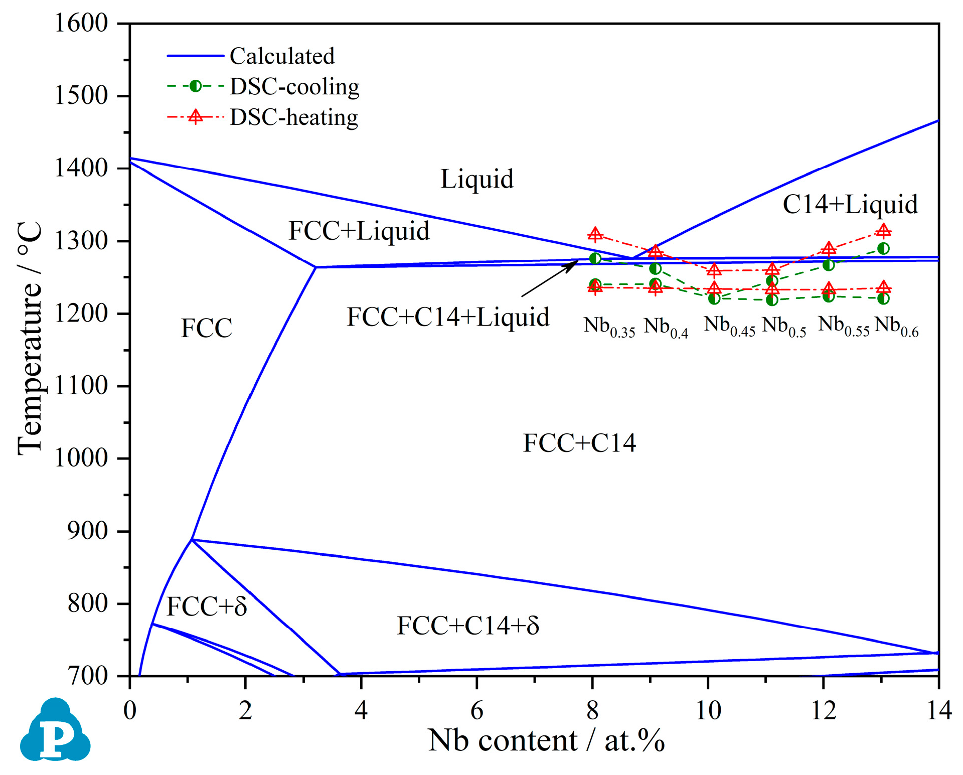
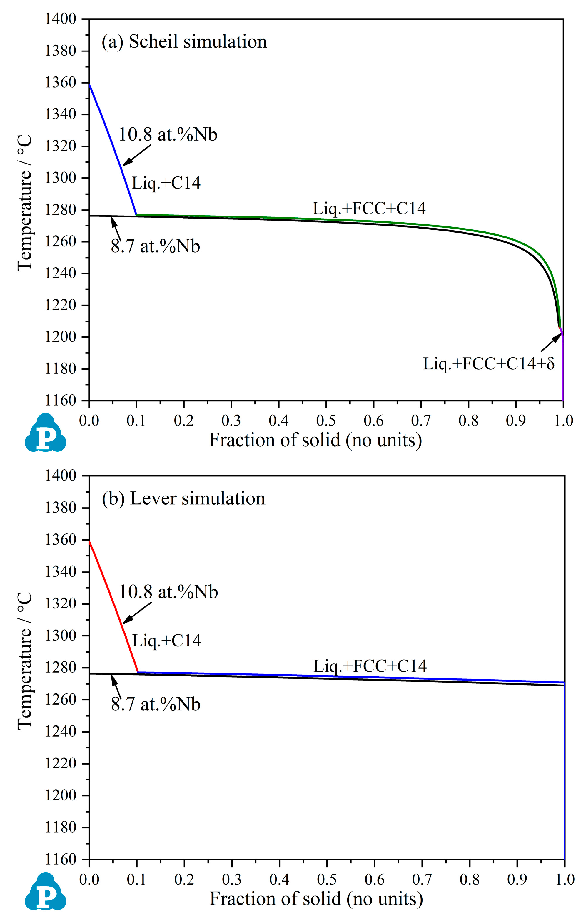
3.1. Thermodynamic Calculation Based on PanNi Database

The calculated vertical section of the CoCrFeNi–Nb pseudo-binary system, based on the PanNi database within the Pandat software, is presented in Figure 1. It is clear that there is a eutectic reaction of Liquid → FCC + C14 at 1276 °C when the liquid phase contains 8.7 at.% Nb. Compared to the available information [8,36,37,38,39,40,41,42], both the calculated Nb content at the eutectic point (8.7 at.% Nb) and the eutectic temperature (1276 °C) are different from the experimental results. It needs to be emphasized that there is a narrow three-phase region of FCC + C14 + Liquid below the eutectic reaction. The calculated composition of the liquid phase (22.6Co–20.9Cr–22.8Fe–24.5Ni–9.2Nb, at.%) is also near the calculated eutectic composition. However, this region did not exist in Ref. [43], in which the phase diagram was calculated based on the Ni-based database in the Thermo-calc software.
To better understand the three-phase region of FCC + C14 + Liquid and the solidification process, Scheil and Lever simulations were performed based on the PanNi database. Since the calculated eutectic point (8.7 at.% Nb) is different from the experimental one (10.8 at.%), both of these two composition were simulated. Both the Scheil simulation results (Figure 2a) and the lever simulation results (Figure 2b) elucidate that the Liquid → FCC + C14 eutectic reaction occurs in a narrow temperature range instead of at a constant temperature. Since the alloy containing 10.8 at.% Nb is a hyper-eutectic alloy in the calculated phase diagram, the pro-eutectic C14 phase forms before the eutectic reaction.
Figure 1 shows that, with decreasing temperature, the solubility of Nb in the FCC phase decreased. The C14 phase may separate from the as-cast FCC phase when the alloy is annealed at above 900 °C, and another phase, δ-Ni3Nb, with an oP8 structure, is stable below 900 °C. However, it needs to be pointed out that the Mg3Cd-type compound τ, which was confirmed in the Co–Ni–Nb system [53,54,55], is not concluded in the PanNi database. The calculated phase diagram may have some deviation. Detailed discussion about the phase diagram and comparisons with the experimental results are presented later.

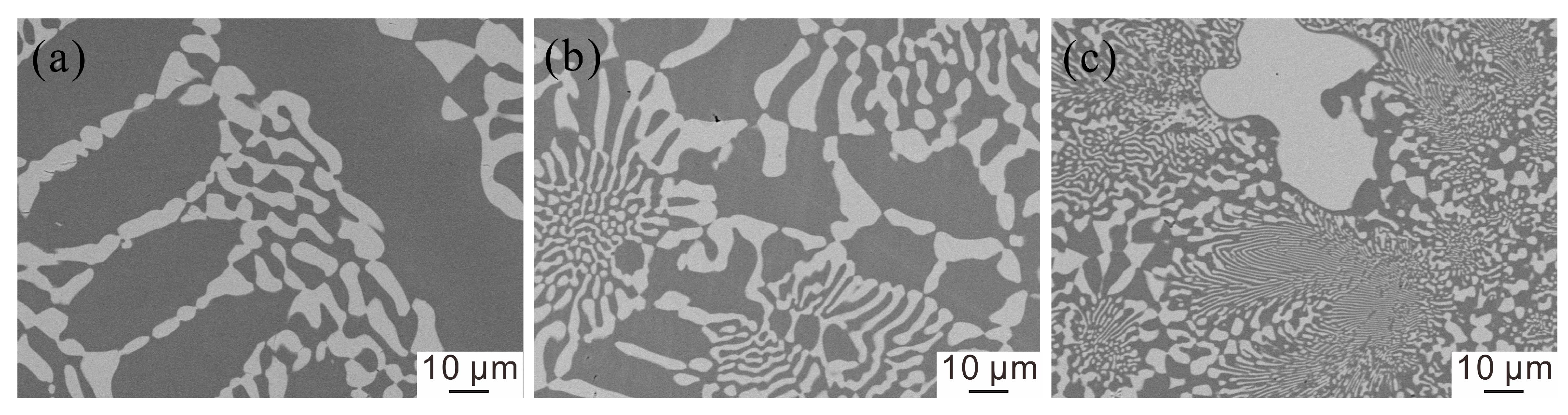
3.2. Microstructure and Phase Constituent of the As-Cast Alloys

The XRD patterns indicate that all the as-cast CoCrFeNiNbx (x = 0.3~0.6) alloys have the same phase constituents and are composed of the FCC + C14 Laves phases, as shown in Figure 3. The BSE images of all the as-cast alloys are presented in Figure 4. It is clear that the lamellar eutectic structure exists in all of them, and the alloy microstructure dramatically varies with Nb atomic ratio (x value). When x ≤ 0.4, the alloys displayed a hypo-eutectic appearance, whereas the alloys displayed hyper-eutectic appearances when x ≥ 0.55. These results agree well with Ref. [43]. Based on the EDS analysis presented in Table 1, it is confirmed that the pro-eutectic FCC phase contains 2.3–2.8% Nb (in alloys Nb0.3~0.4), and the pro-eutectic C14 Laves phase contains 23.7–24.4% Nb (in alloys Nb0.55~0.6). These results are also similar to those of previously published works [37,40]. Compared with the calculated phase diagram (Figure 1), the predicted largest solubility of Nb in the FCC phase is a little higher than the detected Nb content in the pro-eutectic FCC phase. As can be seen in Table 1, the compositions of FCC, C14 and the eutectic region are not significantly affected by the composition of the alloy. The detected composition of the eutectic region is 19.7–22.9% Cr, 21.1–22.5% Fe, 21.1–23.3% Co, 22.3–24.5% Ni and 9.7–12.7% Nb. As can be seen in Figure 4, in all BSE images, the C14 phase is brighter than the FCC phase because it contains much higher Nb content.
According to Figure 4, both alloys Nb0.45 and Nb0.5 are near the eutectic composition. To clearly show the eutectic structure, the BSE images of alloys Nb0.45 and Nb0.5 were photographed with a larger magnification than the other alloys. As can be seen in Figure 4d, the FCC and C14 blocks exist in the boundary of some eutectic regions (region C). The EDS results confirm that the composition of region C is the same as the eutectic region or nominal composition, as shown in Table 1. Therefore, this structure is not caused by composition segregation. Perhaps, for this reason, there is a dispute in the composition of the eutectic region. As can be seen in Figure 4, much larger FCC and C14 blocks exist in the boundary region of the lamellar eutectic structure in all the as-cast CoCrFeNiNbx alloys. As shown in Figure 2, the eutectic reaction occurs in a temperature range of 7 °C. The regions, similar to region C, should be later solidified area. Generally, when small amounts of liquid phase remain after a eutectic reaction, the later formed solid phases grow on the corresponding eutectic phases in subsequent solidification, and their sizes become much larger. Therefore, this kind of structure supports that the eutectic reaction occurs in a temperature range. The simulated solidification process reasonably matches with the experimental observation in most case. As for the δ-Ni3Nb phase, which forms in the Scheil simulation (Figure 2a), it was not detected in the as-cast CoCrFeNiNbx alloys.

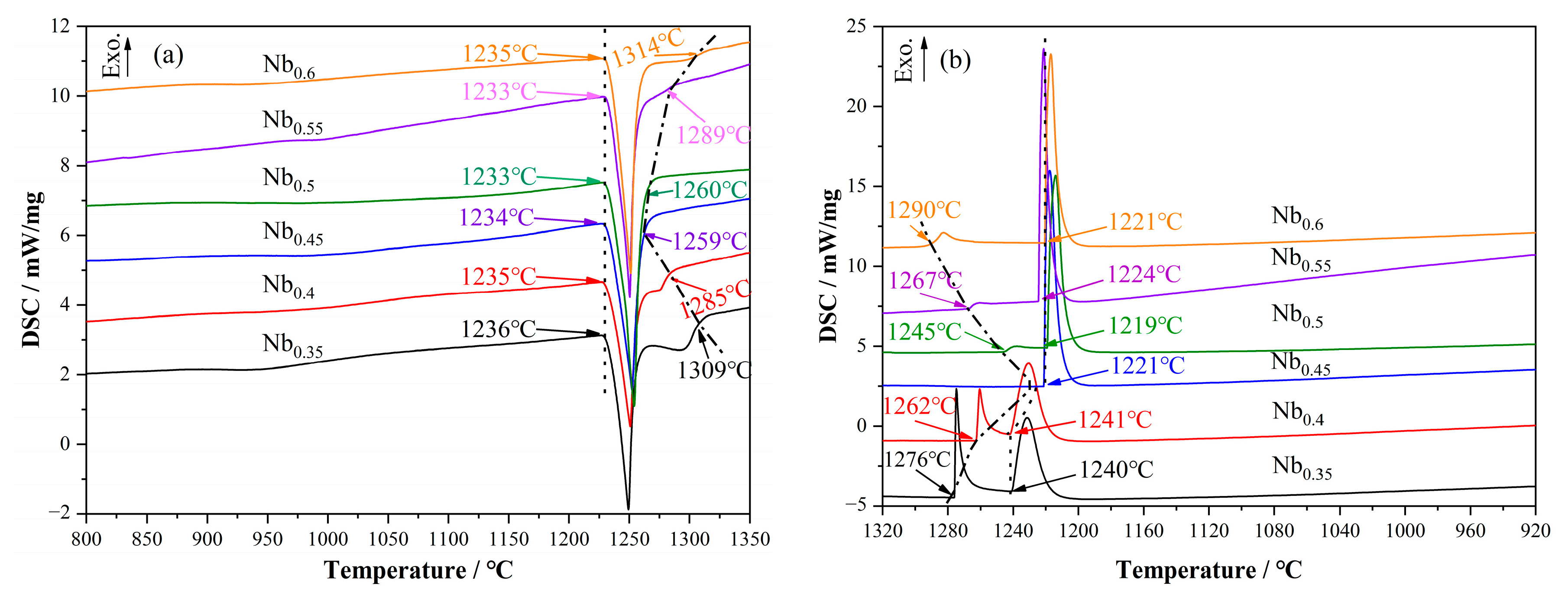
3.3. Heating and Cooling DSC Test

To clearly investigate the eutectic region and phase transformation in the CoCrFeNiNbx system, the as-cast alloys were examined by DSC with a rate of 20 K/min. Both a heating procedure and a cooling procedure were performed. The DSC curves are presented in Figure 5. It is clear that the onset temperatures of the obvious endothermic peaks are 1234 ± 2 °C. Since all the test samples turned to spherical after the DSC test, i.e., they were completely melted, the onset point of the sole endothermic peak during heating should relate to the eutectic reaction temperature. Since both alloys Nb0.45 and Nb0.5 are near the eutectic region (~10.8 at.% Nb) and composed of a lamellar eutectic structure, they have similar heating DSC curves with a sole endothermic peak, as shown in Figure 5a. It is noteworthy that there is an obvious exothermic peak before the eutectic peak in the cooling DSC curve of alloy Nb0.5 (Figure 5b). This suggests that alloy Nb0.45 is a real eutectic alloy and that alloy Nb0.5 is a hyper-eutectic one.
Except for alloys Nb0.45 and Nb0.5, all the other heating DSC curves show a dissolution characteristic after the endothermic peak, as seen in Figure 5a. In other words, these alloys are hypo- or hyper- eutectic ones, and the heat of dissolution was high enough to be detected. The end points of the dissolution platform are related to the liquidus temperature. As seen in Figure 5a, the liquidus temperatures of the CoCrFeNiNbx (x = 0.3–0.6) alloys vary with the x values and reach the lowest values when x = 0.45 or 0.5. Since there is supercooling during the cooling test, the onset temperatures in the cooling curves are 10–20 °C lower than those in the heat curves. The detected onset temperature for the eutectic peak in the cooling procedure of the eutectic and hyper-eutectic alloys (x ≥ 0.45) is 1221 ± 3 °C, which is ~13 °C lower than that in the heating procedure. However, in the hypo-eutectic alloys (x = 0.35, 0.4), it is interesting that the onset temperature of the eutectic reaction increased to 1240–1241 °C, which is 4–6 °C higher than that in the heating procedure. That means that the formation of the pro-eutectic FCC phase can increase the eutectic temperature. As seen in Figure 5b, the formation of the pro-eutectic FCC phase has a strong exothermal effect. This leads to the increase in the eutectic onset temperature. The solidification or dissolution of the C14 Laves phase is much milder. Perhaps, for this reason, Chanda et al. [39] believed that the eutectic composition was CoCrFeNiNb0.5 when judging by the heating DSC curves.
The DSC results are also marked in Figure 1. Compared with the present experiment’s results, the calculated liquidus and eutectic temperatures are much higher than the experimental results. Both the calculated Nb content at the eutectic point (8.7 at.% Nb) and the eutectic temperature (1276 °C) are different from the experimental results. Therefore, more experiments are needed to optimize the thermodynamic parameters in the Co–Cr–Fe–Ni–Nb system.

3.4. Microstructure after the DSC Test

The microstructures of the alloys after the DSC test were also examined by SEM-EDS. As shown in Figure 6, the eutectic structure in the alloys were greatly changed. No fine lamellar structure exists in the eutectic or hypo-eutectic alloys. Taking alloys Nb0.4 and Nb0.45 as examples, the C14 phase was spheroidized and grew. As seen in Figure 6b, a small amount of the coarse lamellar structure, with a chrysanthemum shape, exists in the center of the eutectic region of the eutectic alloy Nb0.45, and a large block FCC and C14 phase formed in the boundary of the eutectic region. No lamellar structure was observed in the hypo-eutectic alloy Nb0.4 (Figure 6a). Moreover, the size of the C14 particles in FCC reached nearly 10 μm. Regarding the alloy Nb0.5, which almost has same microstructure as Nb0.45, a larger than 30 μm C14 block can be clearly observed in Figure 6c. It should be a pro-eutectic C14 phase. Although no pro-eutectic C14 phase exists in the as-cast alloy Nb0.5, the cooling DSC curve of alloy Nb0.5 (Figure 5b) shows a characteristic peak for formation of pro-eutectic C14 phase. This result suggests that Nb0.5 is a hyper-eutectic alloy and that the alloy microstructure is greatly affected by cooling rate.
In the DSC tests, the alloys were cooled from 1400 °C at a rate of 20 K/min. Of course, the cooling rate is much lower than that which is required for casting in a water-cooled copper mold after arc-melting. That means that the microstructure of the CoCrFeNiNbx alloys was greatly affected by the cooling rate. The EDS results in Table 2 indicate that, although the composition of the alloys is different, the chemical compositions of both FCC and C14 phases in them are similar. The composition of the FCC phase stayed at around 23.2Co–24.6Cr–24.9Fe–24.7Ni–2.6Nb (at.%), and the composition of the C14 phase stayed at around 22.9Co–15.1Cr–16.6Fe–20.6Ni–24.8Nb (at.%). Overall, just the volume fraction of the C14 phase increased with the Nb atomic ratio (x value) in the CoCrFeNiNbx alloys, which were cooled at 20 K/min. In addition, as seen in Figure 5, except for the pro-eutectic phases, the size of the FCC and C14 phases decreased with the increase in the Nb ratio (x value).

3.5. Microstructure and Phase Constituents of the 1000 or 800 °C Annealed Alloys

As noted above, the microstructure of the alloy is greatly affected by the cooling rate. To clearly understand microstructure stability, the as-cast CoCrFeNiNbx alloys were vacuum annealed at 800 or 1000 °C for 120 h. The typical XRD patterns and BSE images of the annealed CoCrFeNiNbx alloys are presented in Figure 3 and Figure 7, respectively. There are no obvious differences in the XRD patterns of the annealed and the as-cast alloys. The 1000 °C annealed alloys are also composed of FCC + C14 phases. However, the microstructures of the annealed alloys changed significantly. As seen in Figure 7a–d, the typical lamellar structure in the as-cast alloys totally disappeared after 1000 °C annealing for 120 h. A coarse strip or block C14 phase with a brighter appearance can be clearly distinguished from the FCC phase. With the increase in the x value, the volume fraction of the C14 phase increased, and the appearance of the C14 phase gradually changed from strip-like to blocks. The EDS results in Table 2 indicate that the Nb content of the 1000 °C annealed FCC phase is 2.0–2.5 at.%, which is a little lower than the Nb content after the DSC test (2.3–2.8%). As seen from the thermodynamically calculated phase diagram (Figure 1), the solubility of Nb in FCC decreases with decreasing temperature. As for the C14 phase, its composition is almost the same as that in the DSC-tested alloys.
The BSE images of the 800 °C annealed CoCrFeNiNbx alloys are presented in Figure 7e–h. They are obviously much different from the as-cast or 1000 °C annealed alloys. The lamellar structure still exists in the eutectic alloy Nb0.45 (Figure 7g). However, the lamellar spacing of the eutectic structure increased, and spheroidization can be obviously observed at the boundary of each eutectic region. This indicates that microstructure transformation first starts at the boundary of different eutectic regions. Regarding the hypo-eutectic alloys Nb0.3 and Nb0.35, the degree of spheroidization in the lamellar eutectic structure is more obvious, and a coarse block C14 phase is formed at the boundary with the pro-eutectic FCC phase.
As seen in Table 2, the solubility of Nb in the FCC phase decreased to 1.7 at.%. It is clear that there is a lath-shaped precipitate in the pro-eutectic FCC phase, as shown in Figure 7e,f. He et al. [50] believed that the precipitate is a FCC phase containing 10 at.% Nb. The selected-area diffraction pattern (SADP) of the FCC and precipitate regions showed that some extra spots existed, but they failed to analyze it. The TEM image and SADPs of the 800 °C annealed alloy Nb0.35 are presented in Figure 8. Three phases can be clearly distinguished in the bright field image (Figure 8a). The SADPs in Figure 8b and c confirm the matrix FCC phase and the hexagonal C14 Laves phase, respectively, and the TEM-EDS analysis indicates that the precipitate contained 2.9Cr–4.5Fe–24.1Co–41.1Ni–27.4Nb (at.%). This composition is totally different from the detected C14 phase but is similar to a phase in the 700 °C annealed CoCrFeNiNb alloy. Fan et al. [49] believed that it is the (Ni,Co)3Nb structure, because its Ni content is near 40%. The calculated phase diagram (Figure 1) also suggests that the δ-Ni3Nb phase is stable at 800 °C. However, according to the Co–Nb–Ni ternary phase diagram [53,54,55], a Mg3Cd-type ternary compound τ exists and can equilibrate with the FCC phase, and the δ-(Ni,Co)3Nb phase only equilibrates with the FCC phase when Ni content is higher than 70 at.% at 800 °C. It was found that the SADP of the precipitate (Figure 8d) could be well indexed by the Mg3Cd-type τ phase but not by the δ-(Ni,Co)3Nb or C15 Laves phases. The detected composition of the precipitate is also near the composition of the Mg3Cd-type τ phase in Refs. [53,54]. Therefore, the precipitate in the 800 °C annealed pro-eutectic FCC phase is confirmed to be the Mg3Cd-type τ phase.
Regarding the eutectic alloy Nb0.45 and hyper-eutectic alloys Nb0.5–0.6, no precipitate was detected. The decrease in Nb content from the FCC phase can be consumed to form the C14 phase. Moreover, according to the calculated phase diagram (Figure 1), alloys Nb0.45–0.6 are located in the FCC + C14 two-phase region at 800 °C. Although the Mg3Cd-type τ phase is not concluded in the PanNi database, the boundary of the FCC + C14 two-phase region is reasonable. With the increase in Nb content, the temperature for separating the Mg3Cd-type τ phase decreases.

3.6. Microhardness

In the present work, the microhardness test was carried out to understand the effects of chemical composition and annealing on the mechanical properties of CoCrFeNiNbx alloys. The results are presented in Figure 9. It is clear that the microhardness of the as-cast CoCrFeNiNbx alloys increase with the x value, which is similar to that which can be seen in Refs. [37,43]. It is clear that, with the increase in the Nb atomic ratio (x value), the volume fraction of the harder C14 phase increases and leads to an increase in alloy hardness. However, it needs to be emphasized that the increased rate in the hypo-eutectic alloys (x < 0.45) is a little higher than that in the hyper-eutectic alloys (x > 0.45). This is because the C14 phase is much harder than the FCC phase. The decreased volume fraction of the softer FCC phase has a greater contribution to hardening the alloys.
After being annealed, alloy hardness dramatically changed, as shown in Figure 9. After being annealed at 1000 °C for 120 h, the hardness of the alloys decreased in different levels, as shown in Figure 9. The hardness of the eutectic alloy Nb0.45 decreased for 189 HV. This is because the lamellar structure disappeared, the phase size increased, Nb content in the FCC phase decreased and no phase precipitated in the FCC phase. Moreover, after 1000 °C annealing, the hardness of the hypo-eutectic alloys Nb0.3–0.4 and the hyper-eutectic alloys Nb0.55–0.6 decreased for 60~100 HV and 40~60 HV, respectively. Since all the 1000 °C annealed alloys are composed of an FCC matrix and large C14 blocks, and since the volume fraction of the hard C14 phase increases with x value, the alloys’ hardness linearly increases with the x value.
As clearly shown in Figure 9, the hardness of the alloys Nb0.3–0.45 increased for ~100 HV after being annealed at 800 °C for 120 h. Although the decrease in Nb content in the FCC phase and the coarsened phase can soften the alloys, the precipitate of the Mg3Cd-type τ phase in the FCC phase contributes more to hardening the hypo-eutectic alloys. Therefore, it should be a good method to strengthen or harden the FCC phase by precipitating the Mg3Cd-type τ phase. He et al. [50] also reported that annealing at 750 °C for 7 days increases the strength of the CoCrFeNiNb0.25 alloy without sacrificing ductility.

4. Discussion

Eutectic high-entropy alloys (EHEAs), which are composed of a lamellar structure, provide a good combination of strength and ductility [25,27,28,29]. The lamellar eutectic structure in the AlCoCrFeNi2.1 alloy is very stable and can bear annealing at 1000 °C for 240 h [48]. However, as presented above, the lamellar FCC + C14 eutectic structure is dramatically affected by the cooling rate or annealing treatment. The driving force for the spheroidization of the C14 phase is very large. When the ingot solidifies, one phase in the eutectic easily grows up attached to the pro-eutectic phase (FCC or C14); therefore, the pro-eutectic phase is surrounded by another phase. Therefore, as shown in Figure 4, the pro-eutectic FCC phase is enclosed by coarse white the C14 phase in the hypo-eutectic alloy Nb0.3–0.4, whereas the pro-eutectic C14 phase is surrounded by the dark FCC phase in the hyper-eutectic alloy Nb0.5–0.6. Moreover, some FCC and C14 blocks can be found in the boundary of each eutectic region due to the eutectic reaction that occurs within a temperature range of 7 °C. These phenomena indicate that the interface energy between FCC and C14 is large and that Nb has a fast diffusion rate in the FCC and C14 interface. Even when the alloy has just been cooled at 20 K/min, a large block C14 phase can form, as shown in Figure 6. For the same reason, the lamellar FCC + C14 eutectic structure is not stable at elevated temperatures, such as 800 °C. Therefore, when producing large parts with Co–Cr–Fe–Ni–Nb alloys, it is difficult to obtain a uniform lamellar FCC + C14 eutectic structure.
Generally, the diffusion rate of elements in the Co–Cr–Fe–Ni or Co–Cr–Fe–Mn–Ni alloys is slow, i.e., the diffusion effect of the high-entropy alloys is sluggish. It is interesting that the Nb atom has an appreciable diffusion rate in the CoCrFeNiNbx alloys, although the radius of the Nb atom is much larger than that of Co, Cr, Fe and Ni atoms. As seen in Figure 7, after being annealed at 800 °C for 120 h, the eutectic structure obviously became spheroidized, and the Mg3Cd-type τ phase was also obviously precipitated in the FCC phase. Most probably, Nb atoms can quickly diffuse through boundaries between phases or crystals. Unfortunately, there is no available information about the diffusion coefficient of Nb in CoCrFeNiNbx alloys.
The solubility of Nb in the as-cast FCC phase is below 2.8 at.% and decreases with decreasing annealing temperature. Regarding the CoCrFeNiNbx alloys, Nb content that slightly exceeds this value may produce larger C14 particles. The addition of Nb into the FCC phase not only has a good solid solution strengthening effect, but it also has an excellent precipitation strengthening effect. Moreover, it is also believed that the eutectic point is on Nb0.65 [43,56]. In their experiment, the ingot, which was 60 (or 70) mm in length and 10 (or 3) mm in diameter, was much larger than the ingot in the present work, which may be the reason for the divergence.

5. Conclusions

(1)
All the as-cast or 1000 °C annealed CoCrFeNiNbx (x = 0.3–0.6) alloys are composed of FCC and C14 Laves phases. Their compositions change minimally with x values, cooling rates or annealing treatments. Moreover, the Nb content in the C14 phase stays at around 24.5 at.%.
(2)
The eutectic reaction of Liquid → FCC + C14 occurs in a narrow temperature range and starts at 1234 °C near CoCrFeNiNb0.45 in the CoCrFeNi–Nb pseudo-binary system.
(3)
The microstructure of the CoCrFeNiNbx alloys is greatly affected by the cooling rate and annealing treatment. The C14 phase is easily spheroidized during annealing. Special attention should be paid to the effects of the cooling rate and annealing treatment when preparing Co–Cr–Fe–Ni–Nb alloys.
(4)
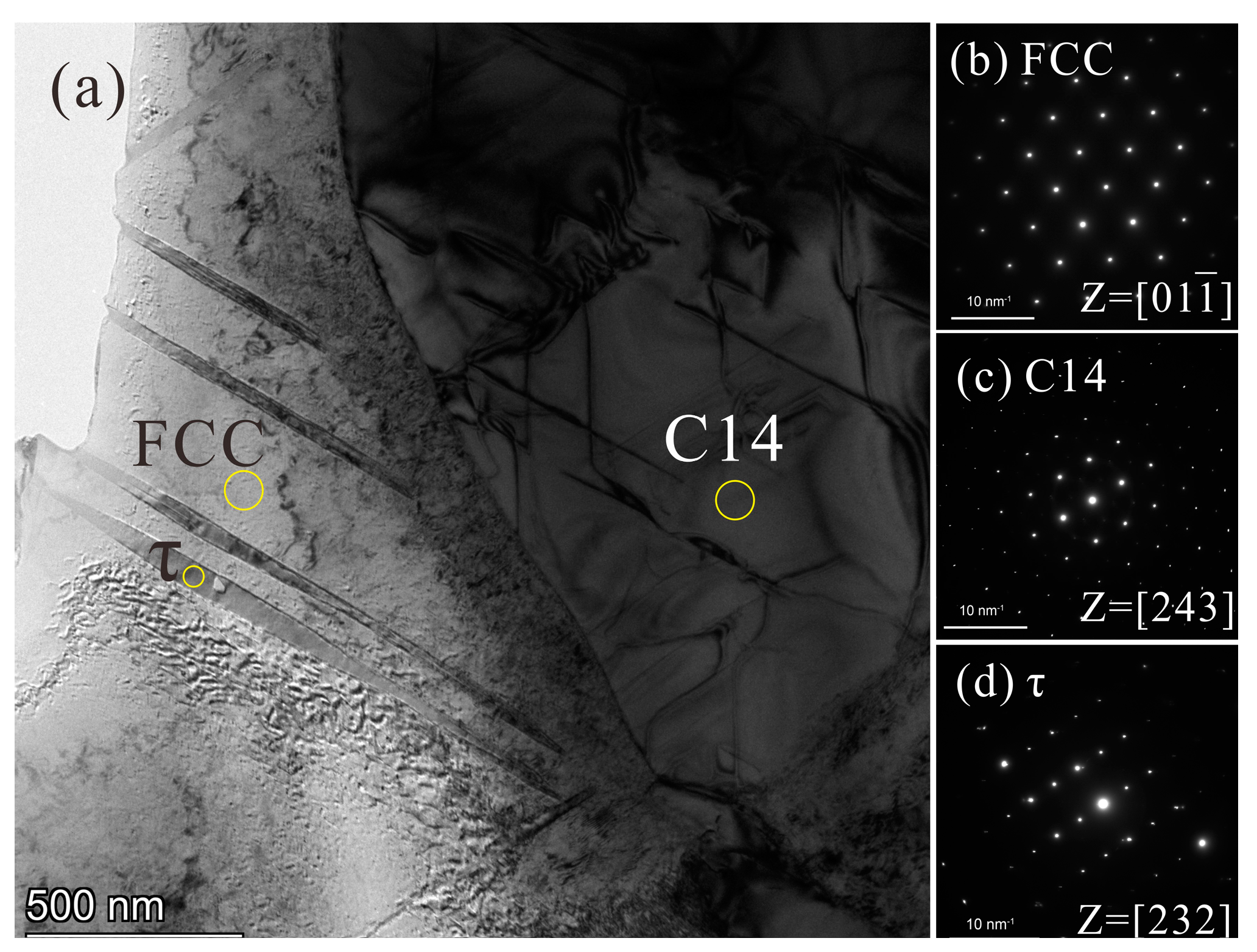
The solubility of Nb in the FCC phase decreases with decreasing temperature. It has been confirmed that, after annealing at 800 °C for 120 h, the needle-like nano Mg3Cd-type τ phase, with a composition of 2.9Cr–4.5Fe–24.1Co–41.1Ni–27.4Nb (at.%), precipitated from the pro-eutectic FCC phase and led to an increase in alloy microhardness for ~100 HV. This may be a good method to strengthen the FCC phase.
(5)
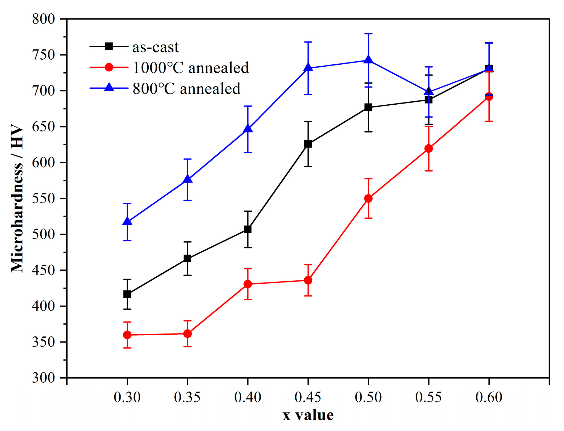
The microhardness of the CoCrFeNiNbx alloys increases with the x value. The increased rate in hypo-eutectic alloys (x < 0.45) is a little higher than that in hyper-eutectic alloys (x > 0.45).

Author Contributions

Conceptualization, C.W.; Data curation, X.C., C.W. and H.P.; Formal analysis, X.C., C.W., Y.L., H.P. and X.S.; Funding acquisition, C.W. and X.S.; Investigation, X.C.; Methodology, C.W.; Project administration, C.W. and X.S.; Writing—original draft preparation, X.C.; Writing—review and editing, C.W. and Y.L. All authors have read and agreed to the published version of the manuscript.

Funding

This research was funded by the financial support from the National Natural Science Foundation of China (Nos. 51771035 and 51871030) and from the Priority Academic Program Development of Jiangsu Higher Education Institutions.

Institutional Review Board Statement

Not applicable.

Informed Consent Statement

Not applicable.

Data Availability Statement

Not applicable.

Conflicts of Interest

The authors declare no conflict of interest.

References

  1. Miracle, D.B.; Senkov, O.N. A critical review of high entropy alloys and related concepts. Acta Mater. 2017, 122, 448–511. [Google Scholar] [CrossRef] [Green Version]
  2. Yeh, J.W.; Chen, S.K.; Lin, S.J.; Gan, J.Y.; Chin, T.S.; Shun, T.T.; Tsau, C.H.; Chang, S.Y. Nanostructured High-Entropy Alloys with Multiple Principal Elements: Novel Alloy Design Concepts and Outcomes. Adv. Eng. Mater. 2004, 6, 299–303. [Google Scholar] [CrossRef]
  3. Zhang, Y.; Zuo, T.T.; Tang, Z.; Gao, M.; Dahmen, K.A.; Liaw, P.K.; Lu, Z.P. Microstructures and properties of high-entropy alloys. Prog. Mater. Sci. 2014, 61, 1–93. [Google Scholar] [CrossRef]
  4. Cantor, B.; Chang, I.T.H.; Knight, P.; Vincent, A.J.B. Microstructural development in equiatomic multicomponent alloys. Mater. Sci. Eng. A 2004, 375–377, 213–218. [Google Scholar] [CrossRef]
  5. Yeh, J.W.; Lin, S.J.; Chin, T.S.; Gan, J.Y.; Chen, S.K.; Shun, T.T.; Tsau, C.H.; Chou, S.Y. Formation of simple crystal structures in Cu-Co-Ni-Cr-Al-Fe-Ti-V alloys with multiprincipal metallic elements. Metall. Mater. Trans. A 2004, 35, 2533–2536. [Google Scholar] [CrossRef]
  6. Maity, T.; Prashanth, K.G.; Balcı, O.; Kim, J.T.; Schöberl, T.; Wang, Z.; Eckert, J. Influence of severe straining and strain rate on the evolution of dislocation structures during micro-/nanoindentation in high entropy lamellar eutectics. Int. J. Plast. 2018, 109, 121–136. [Google Scholar] [CrossRef]
  7. Zhang, M.; Zhang, L.; Fan, J.; Yu, P.; Li, G. Novel Co-free CrFeNiNb0.1Tix high-entropy alloys with ultra high hardness and strength. Mater. Sci. Eng. A 2019, 764, 138212. [Google Scholar] [CrossRef]
  8. Průša, F.; Cabibbo, M.; Šenková, A.; Kučera, V.; Veselka, Z.; Školáková, A.; Vojtěch, D.; Cibulková, J.; Čapek, J. High-strength ultrafine-grained CoCrFeNiNb high-entropy alloy prepared by mechanical alloying: Properties and strengthening mechanism. J. Alloys Compd. 2020, 835, 155308. [Google Scholar] [CrossRef]
  9. Lu, J.; Wang, Z.; Wang, W.; Zhou, K.; He, F.; Wang, Z. Superior Slurry Erosion Behavior of a Casting NiCoCrFeNb0.45 Eutectic High Entropy Alloy. Acta Metall. Sinica Engl. Lett. 2020, 33, 1111–1116. [Google Scholar] [CrossRef]
  10. Ma, M.; Han, A.; Zhang, Z.; Lian, Y.; Zhao, C.; Zhang, J. The role of Si on microstructure and high-temperature oxidation of CoCr2FeNb0.5Ni high-entropy alloy coating. Corros. Sci. 2021, 185, 109417. [Google Scholar] [CrossRef]
  11. He, F.; Wang, Z.; Wang, J.; Wu, Q.; Chen, D.; Han, B.; Li, J.; Wang, J.; Kai, J.J. Abnormal γ″-ε phase transformation in the CoCrFeNiNb0.25 high entropy alloy. Scr. Mater. 2018, 146, 281–285. [Google Scholar] [CrossRef]
  12. Chanda, B.; Das, J. An assessment on the stability of the eutectic phases in high entropy alloys. J. Alloys Compd. 2019, 798, 167–173. [Google Scholar] [CrossRef]
  13. Wang, J.; Wu, S.; Fu, S.; Liu, S.; Yan, M.; Lai, Q.; Lan, S.; Hahn, H.; Feng, T. Ultrahigh hardness with exceptional thermal stability of a nanocrystalline CoCrFeNiMn high-entropy alloy prepared by inert gas condensation. Scr. Mater. 2020, 187, 335–339. [Google Scholar] [CrossRef]
  14. Otto, F.; Dlouhý, A.; Somsen, C.; Bei, H.; Eggeler, G.; George, E.P. The influences of temperature and microstructure on the tensile properties of a CoCrFeMnNi high-entropy alloy. Acta Mater. 2013, 61, 5743–5755. [Google Scholar] [CrossRef] [Green Version]
  15. Chanda, B.; Verma, A.; Das, J. Nano-/Ultrafine Eutectic in CoCrFeNi(Nb/Ta) High-Entropy Alloys. Trans. Indian Inst. Met. 2018, 71, 2717–2723. [Google Scholar] [CrossRef]
  16. Liu, W.H.; He, J.Y.; Huang, H.L.; Wang, H.; Lu, Z.P.; Liu, C.T. Effects of Nb additions on the microstructure and mechanical property of CoCrFeNi high-entropy alloys. Intermetallics 2015, 60, 1–8. [Google Scholar] [CrossRef]
  17. Varvenne, C.; Luque, A.; Curtin, W.A. Theory of strengthening in fcc high entropy alloys. Acta Mater. 2016, 118, 164–176. [Google Scholar] [CrossRef] [Green Version]
  18. Wu, C.; Sun, Y.; Liu, Y.; Tu, H. Effect of Long-Time Annealing at 1000 °C on Phase Constituent and Microhardness of the 20Co-Cr-Fe-Ni Alloys. Materials 2019, 12, 1700. [Google Scholar] [CrossRef] [Green Version]
  19. Senkov, O.N.; Wilks, G.B.; Scott, J.M.; Miracle, D.B. Mechanical properties of Nb25Mo25Ta25W25 and V20Nb20Mo20Ta20W20 refractory high entropy alloys. Intermetallics 2011, 19, 698–706. [Google Scholar] [CrossRef]
  20. Senkov, O.N.; Jensen, J.K.; Pilchak, A.L.; Miracle, D.B.; Fraser, H.L. Compositional variation effects on the microstructure and properties of a refractory high-entropy superalloy AlMo0.5NbTa0.5TiZr. Mater. Des. 2018, 139, 498–511. [Google Scholar] [CrossRef]
  21. Jiang, H.; Zhang, H.; Huang, T.; Lu, Y.; Wang, T.; Li, T. Microstructures and mechanical properties of Co2MoxNi2VWx eutectic high entropy alloys. Mater. Des. 2016, 109, 539–546. [Google Scholar] [CrossRef]
  22. Yang, H.; Tan, Y.; Qiao, J.; Hawk, J.A.; Zhang, Y.; Gao, M.; Liaw, P.K. Optimize the Mechanical Properties of Al0.6CoCrFeNi High-Entropy Alloys by Thermo-Mechanical Processing. Metals 2022, 12, 178. [Google Scholar] [CrossRef]
  23. Yu, Y.; He, F.; Qiao, Z.H.; Wang, Z.J.; Liu, W.M.; Yang, J. Effects of temperature and microstructure on the triblogical properties of CoCrFeNiNbx eutectic high entropy alloys. J. Alloys Compd. 2019, 775, 1376–1385. [Google Scholar] [CrossRef]
  24. Chanda, B.; Potnis, G.; Jana, P.P.; Das, J. A review on nano-/ultrafine advanced eutectic alloys. J. Alloys Compd. 2020, 827, 154226. [Google Scholar] [CrossRef]
  25. Lu, Y.; Dong, Y.; Guo, S.; Jiang, L.; Kang, H.; Wang, T.; Wen, B.; Wang, Z.; Jie, J.; Cao, Z.; et al. A Promising New Class of High-Temperature Alloys: Eutectic High-Entropy Alloys. Sci. Rep. 2014, 4, 6200. [Google Scholar] [CrossRef]
  26. Jiang, L.; Lu, Y.; Dong, Y.; Wang, T.; Cao, Z.; Li, T. Effects of Nb addition on structural evolution and properties of the CoFeNi2V0.5 high-entropy alloy. Appl. Phys. A 2015, 119, 291–297. [Google Scholar] [CrossRef]
  27. Shi, P.; Li, R.; Li, Y.; Wen, Y.; Zhong, Y.; Ren, W.; Shen, Z.; Zheng, T.; Peng, J.; Liang, X. Hierarchical crack buffering triples ductility in eutectic herringbone high-entropy alloys. Science 2021, 373, 912–918. [Google Scholar] [CrossRef]
  28. Wu, Q.; Wang, Z.; Hu, X.; Zheng, T.; Yang, Z.; He, F.; Li, J.; Wang, J. Uncovering the eutectics design by machine learning in the Al–Co–Cr–Fe–Ni high entropy system. Acta Mater. 2020, 182, 278–286. [Google Scholar] [CrossRef]
  29. Xiong, T.; Yang, W.; Zheng, S.; Liu, Z.; Lu, Y.; Zhang, R.; Zhou, Y.; Shao, X.; Zhang, B.; Wang, J.; et al. Faceted Kurdjumov-Sachs interface-induced slip continuity in the eutectic high-entropy alloy, AlCoCrFeNi2.1. J. Mater. Sci. Technol. 2021, 65, 216–227. [Google Scholar] [CrossRef]
  30. Jin, X.; Zhou, Y.; Zhang, L.; Du, X.Y.; Li, B.S. A novel Fe20Co20Ni41Al19 eutectic high entropy alloy with excellent tensile properties. Mater. Lett. 2018, 216, 144–146. [Google Scholar] [CrossRef]
  31. Lu, Y.; Jiang, H.; Guo, S.; Wang, T.; Cao, Z.; Li, T. A new strategy to design eutectic high-entropy alloys using mixing enthalpy. Intermetallics 2017, 91, 124–128. [Google Scholar] [CrossRef]
  32. Lu, Y.; Dong, Y.; Jiang, H.; Wang, Z.; Cao, Z.; Guo, S.; Wang, T.; Li, T.; Liaw, P.K. Promising properties and future trend of eutectic high entropy alloys. Scr. Mater. 2020, 187, 202–209. [Google Scholar] [CrossRef]
  33. Dong, Y.; Gao, X.; Lu, Y.; Wang, T.; Li, T. A multi-component AlCrFe2Ni2 alloy with excellent mechanical properties. Mater. Lett. 2016, 169, 62–64. [Google Scholar] [CrossRef]
  34. Wei, C.B.; Du, X.H.; Lu, Y.P.; Jiang, H.; Li, T.J.; Wang, T.M. Novel as-cast AlCrFe2Ni2Ti0.5 high-entropy alloy with excellent mechanical properties. Int. J. Miner. Metall. Mater. 2020, 27, 1312–1317. [Google Scholar] [CrossRef]
  35. Jiang, H.; Han, K.; Gao, X.; Lu, Y.; Cao, Z.; Gao, M.C.; Hawk, J.A.; Li, T. A new strategy to design eutectic high-entropy alloys using simple mixture method. Mater. Des. 2018, 142, 101–105. [Google Scholar] [CrossRef]
  36. Jiang, H.; Qiao, D.; Lu, Y.; Ren, Z.; Cao, Z.; Wang, T.; Li, T. Direct solidification of bulk ultrafine-microstructure eutectic high-entropy alloys with outstanding thermal stability. Scr. Mater. 2019, 165, 145–149. [Google Scholar] [CrossRef]
  37. Jiang, H.; Jiang, L.; Qiao, Q.; Lu, Y.; Wang, T.; Cao, Z.; Li, T. Effect of Niobium on Microstructure and Properties of the CoCrFeNb x Ni High Entropy Alloys. J. Mater. Sci. Technol. 2017, 33, 712–717. [Google Scholar] [CrossRef]
  38. An, X.; Chu, C.; Zhao, H.; Shen, B.; Zhou, L.; Chu, P.K. CoNiFeNb0.45 eutectic multi-principal element alloy with excellent mechanical properties and corrosion resistance. Mater. Sci. Eng. A 2020, 777, 139026. [Google Scholar] [CrossRef]
  39. Chanda, B.; Das, J. Composition Dependence on the Evolution of Nanoeutectic in CoCrFeNiNbx (0.45  ≤  x ≤  0.65) High Entropy Alloys. Adv. Eng. Mater. 2018, 20, 1700908. [Google Scholar] [CrossRef]
  40. Chung, D.; Ding, Z.Y.; Yang, Y. Hierarchical Eutectic Structure Enabling Superior Fracture Toughness and Superb Strength in CoCrFeNiNb0.5 Eutectic High Entropy Alloy at Room Temperature. Adv. Eng. Mater. 2019, 21, 1801060. [Google Scholar] [CrossRef]
  41. He, Q.F.; Ding, Z.Y.; Ye, Y.F.; Yang, Y. Design of High-Entropy Alloy: A Perspective from Nonideal Mixing. JOM. 2017, 69, 2092–2098. [Google Scholar] [CrossRef]
  42. Xiang, K.; Chen, L.Y.; Chai, L.; Guo, N.; Wang, H. Microstructural characteristics and properties of CoCrFeNiNbx high-entropy alloy coatings on pure titanium substrate by pulsed laser cladding. Appl. Surf. Sci. 2020, 517, 146214. [Google Scholar] [CrossRef]
  43. He, F.; Wang, Z.; Cheng, P.; Wang, Q.; Li, J.; Dang, Y.; Wang, J.; Liu, C.T. Designing eutectic high entropy alloys of CoCrFeNiNbx. J. Alloys Compd. 2016, 656, 284–289. [Google Scholar] [CrossRef]
  44. Wu, C.J.; Zhou, C.; Zeng, J.F.; Liu, Y.; Tu, H.; Su, X.P. Effects of annealing at 800 and 1000 °C on phase precipitates and hardness of Al7Cr20FexNi73−x alloys. Trans. Nonferrous Metal. Soc. China 2021, 31, 734–743. [Google Scholar] [CrossRef]
  45. Sun, Y.; Wu, C.J.; Peng, H.P.; Liu, Y.; Wang, J.H.; Su, X.P. Phase Constituent and Microhardness of As-Cast and Long-Time Annealed AlxCo2-xCrFeNi Multicomponent Alloys. J. Phase Equilib. Diffus. 2019, 40, 706–714. [Google Scholar] [CrossRef]
  46. Nagase, T.; Takemura, M.; Matsumuro, M.; Maruyama, T. Solidification microstructure of AlCoCrFeNi2.1 eutectic high entropy alloy ingots. Mater. Trans. 2018, 59, 255–264. [Google Scholar] [CrossRef] [Green Version]
  47. Nassar, A.; Mullis, A.; Cochrane, R.; Aslam, Z.; Micklethwaite, S.; Cao, L. Rapid solidification of AlCoCrFeNi2.1 High-entropy Alloy. J. Alloys Compd. 2022, 900, 163350. [Google Scholar] [CrossRef]
  48. Wu, C.J.; Xiong, W.; Zhou, C.; Liu, Y.; Su, X. Effect of annealing temperature on microstructure and hardness of Al-Co-Cr-Fe-Ni high-entropy alloy. J. Changzhou Univ. (Nat. Sci. Ed.) 2021, 33, 1–8. [Google Scholar]
  49. Fan, A.C.; Li, J.H.; Tsai, M.H. On the phase constituents of three CoCrFeNiX (X = V, Nb, Ta) high-entropy alloys after prolonged annealing. J. Alloys Compd. 2020, 823, 153524. [Google Scholar] [CrossRef]
  50. He, F.; Wang, Z.; Niu, S.; Wu, Q.; Li, J.; Wang, J.; Liu, C.T.; Dang, Y. Strengthening the CoCrFeNiNb0.25 high entropy alloy by FCC precipitate. J. Alloys Compd. 2016, 667, 53–57. [Google Scholar] [CrossRef]
  51. Chanda, B.; Das, J. Evolution of microstructure homogeneity and mechanical properties in nano-/ultrafine eutectic CoCrFeNiNbx (0.45 ≤ x ≤ 0.65) high entropy alloy ingots and cast rods. J. Alloys Compd. 2022, 910, 163610. [Google Scholar] [CrossRef]
  52. PanNi-Thermodynamic Database for Nickel-Based Superalloys for Pandat. 2021. Available online: https://computherm.com/pannickel (accessed on 20 March 2022).
  53. Shaipov, R.K.; Kerimov, E.Y.; Slyusarenko, E.M. Isothermal sections of the Co-Nb-Ni phase diagram at 1200 and 1375 K. J. Alloys Compd. 2018, 742, 466–479. [Google Scholar] [CrossRef]
  54. Zhou, C.; Guo, C.; Li, J.; Li, C.; Du, Z. Key Experiments and Thermodynamic Description of the Co-Nb-Ni System. Metall. Mater. Trans. A 2020, 51, 5892–5911. [Google Scholar] [CrossRef]
  55. Zhu, L.; Wei, C.; Jiang, L.; Jin, Z.; Zhao, J.C. Experimental determination of the phase diagrams of the Co-Ni-X (X = W, Mo, Nb, Ta) ternary systems using diffusion multiples. Intermetallics 2018, 93, 20–29. [Google Scholar] [CrossRef]
  56. Maity, T.; Prashanth, K.G.; Balçi, O.; Wang, Z.; Jia, Y.D.; Eckert, J. Plastic deformation mechanisms in severely strained eutectic high entropy composites explained via strain rate sensitivity and activation volume. Compos. Part B Eng. 2018, 150, 7–13. [Google Scholar] [CrossRef]
Figure 1. Thermodynamically calculated vertical section of the CoCrFeNi–Nb pseudo-binary system based on the PanNi database with the Pandat software. The present DSC results are also included. The predicted stable δ phase below 900 °C is not accurate enough because the Mg3Cd-type compound τ is not included in the PanNi database.
Metals 12 00756 g001
Figure 2. Solidification simulation of the CoCrFeNi–Nb alloys with (a) Scheil and (b) lever models based on PanNi database. The alloy containing 8.7 at.% Nb is the calculated eutectic alloy, whereas that which contains 10.8 at.% Nb is an experimentally determined eutectic alloy.
Metals 12 00756 g002
Figure 3. XRD patterns of some as-cast and annealed CoCrFeNiNbx alloys.
Metals 12 00756 g003
Figure 4. BSE micrographs of the as-cast CoCrFeNiNbx alloys. Large FCC and C14 blocks exist in the boundary region of the lamellar eutectic structure. (a) Nb0.3; (b) Nb0.35; (c) Nb0.4; (d) Nb0.45; (e) Nb0.5; (f) Nb0.55; (g) Nb0.6.
Metals 12 00756 g004
Figure 5. DSC curves of the as-cast CoCrFeNiNbx alloys with a 20 K/min rate: (a) Heating curves; (b) Cooling curves.
Metals 12 00756 g005
Figure 6. BSE micrographs of the CoCrFeNiNbx alloys after DSC testing, in which the alloys were cooled from 1400 °C at a rate of 20 K/min: (a) Nb0.4; (b) Nb0.45; (c) Nb0.5.
Metals 12 00756 g006
Figure 7. BSE micrographs of the CoCrFeNiNbx alloys after being annealed at 1000 or 800 °C for 120 h: (a) 1000 °C annealed Nb0.3; (b) 1000 °C annealed Nb0.35; (c) 1000 °C annealed Nb0.45; (d) 1000 °C annealed Nb0.6; (e) 800 °C annealed Nb0.3; (f) 800 °C annealed Nb0.35; (g) 800 °C annealed Nb0.45; (h) 800 °C annealed Nb0.6.
Metals 12 00756 g007
Figure 8. TEM images of the CoCrFeNiNb0.35 alloy after being annealed at 800 °C for 120 h: (a) Bright field image; (b) SADP of FCC phase; (c) SADP of C14 Laves phase; (d) SADP of precipitation Mg3Cd-type τ phase.
Metals 12 00756 g008
Figure 9. Microhardness of the CoCrFeNiNbx alloys in as-cast or annealed states.
Metals 12 00756 g009
Table 1. The detected compositions of the alloys, phases and eutectic regions in the as-cast CoCrFeNiNbx alloys by SEM-EDS (at.%).
AlloysRegion/PhaseChemical Composition (at.%)
CrFeCoNiNb
Nb0.3alloy22.522.322.824.57.9
FCC23.926.623.623.52.4
C14 Laves14.216.323.623.022.9
Eutectic19.721.123.323.212.7
Nb0.35alloy22.822.223.123.18.8
FCC24.825.323.324.32.3
C14 Laves14.915.423.124.322.3
Eutectic20.722.523.222.311.3
Nb0.4alloy22.121.722.224.19.9
FCC24.525.223.224.32.8
C14 Laves14.616.223.922.422.9
Eutectic20.421.422.224.311.7
Nb0.45alloy/Eutectic21.622.322.922.710.5
Region C21.121.122.824.210.8
Nb0.5alloy20.822.521.723.211.8
Eutectic21.422.521.124.310.7
Nb0.55alloy20.321.221.524.212.8
FCC22.822.620.929.24.5
C14 Laves15.619.923.916.923.7
Eutectic22.921.322.223.99.7
Nb0.6alloy21.121.221.323.213.2
FCC24.522.921.126.84.7
C14 Laves16.419.422.916.924.4
Eutectic22.321.321.124.510.8
Table 2. Detected phase composition of the CoCrFeNiNbx alloys in different states.
AlloysStatesPhasesChemical Composition (at.%)
CrFeCoNiNb
Nb0.4after DSCFCC24.325.323.524.12.8
C14 Laves14.616.223.421.124.7
Nb0.45after DSCFCC24.925.623.223.92.4
C14 Laves15.716.622.620.224.9
Nb0.5after DSCFCC24.723.822.726.22.6
C14 Laves14.916.922.820.524.9
Nb0.351000 °C
annealed
FCC25.125.924.222.82.0
C14 Laves15.215.926.318.124.5
Nb0.451000 °C
annealed
FCC25.925.921.524.62.1
C14 Laves16.616.223.221.422.6
Nb0.51000 °C
annealed
FCC24.724.921.426.52.5
C14 Laves14.717.522.120.525.2
Nb0.551000 °C
annealed
FCC26.323.120.827.42.4
C14 Laves17.716.322.218.924.9
Nb0.35800 °C
annealed
FCC a26.925.422.123.91.7
C14 Laves a13.917.426.318.124.3
Mg3Cd-type τ a2.94.524.141.127.4
Nb0.55800 °C
annealed
FCC24.725.621.925.22.6
C14 Laves13.817.226.218.524.3
a Detected by TEM-EDS. The other compositions are detected by SEM-EDS.
Publisher’s Note: MDPI stays neutral with regard to jurisdictional claims in published maps and institutional affiliations.

