Article

Study on Stress Corrosion Cracking Behavior of Incoloy825/X65 Bimetallic Composite Pipe Welded Joint in Wet Hydrogen Sulfide Environment

1
School of Materials Science and Engineering, China University of Petroleum (East China), Qingdao 266580, China
2
TSMC China Company Limited, Shanghai 201616, China
3
School of New Energy, China University of Petroleum (East China), Qingdao 266580, China
*
Author to whom correspondence should be addressed.
Metals 2022, 12(4), 632; https://doi.org/10.3390/met12040632
Submission received: 11 March 2022 / Revised: 31 March 2022 / Accepted: 4 April 2022 / Published: 7 April 2022
(This article belongs to the Special Issue Environmental Degradation of Structural Materials)

Abstract

:
The stress corrosion cracking behavior of an Incoloy825/X65 bimetallic composite pipe welded joint in wet hydrogen sulfide (H2S) environment was investigated by means of the creviced bent beam (CBB) test in this study. The microstructure, element distribution and crack propagation behavior of the welded joint were analyzed by optical microscope (OM), scanning electron microscope (SEM), electron dispersive spectroscopy (EDS) and electron backscatter diffraction (EBSD). The results showed that two types of cracks were observed in the Incoloy825/X65 bimetallic composite pipe welded joint in wet H2S environment, they initiated from the notch and the intersection of the three zones (cladding Incoloy825, base X65 and weld), respectively, and propagated along the fusion boundary(FB) and the Type-II-like grain boundary. The mechanisms of the two types of cracks are due to the combination of anodic dissolution, stress and hydrogen. Near the FB, there are high angle grain boundaries, Type-I, Type-II and the Type-II-like grain boundaries, which have high SCC sensitivity. The element distribution in the intersection of the three zones and the crack tip is complex, with element diffusion, Cr loss and large residual strain. All these provide the conditions for cracks initiation and propagation.

1. Introduction

During the development of high-sulfur oil and gas fields, oil and gas transportation pipelines will be eroded by corrosive media such as H2S, CO2 and Cl, resulting in increasingly serious pipeline corrosion problems, among which wet H2S is the main reason for pipeline corrosion [1]. Wet H2S reacts with steel to generate hydrogen atoms, a part of which penetrates the steel, and the diffusing hydrogen can cause hydrogen-induced cracking (HIC) or SCC at stress concentrations or non-metallic inclusions [2]. At present, a large number of studies have been carried out on the wet H2S corrosion of pipeline steel, mainly focusing on the mechanism of HIC and hydrogen sulfide stress corrosion cracking (SSCC). Reaction temperature, partial pressure of H2S, solution medium and pH also have a great influence on the corrosion process of H2S [3,4]. Nickel-based corrosion resistant alloys with high content of Ni, Cr and Mo have an excellent performance to H2S corrosion, but nickel-based alloys are so expensive that their applications are limited [5,6,7]. The bimetallic composite pipe prepared with nickel-based alloy as cladding is widely used in oil and gas pipelines containing H2S due to its cost-effective characteristic, excellent corrosion resistance and excellent mechanical property [8,9,10].
Due to the melting and solidification process of cladding, base and filler metal during welding of bimetallic composite pipes, problems such as element diffusion and nonuniform microstructure will inevitably be introduced, and the difference of microstructure will lead to the non-uniformity of mechanical properties [11,12]. Celin et al. [13] explained this inhomogeneity by investigating the multiple-passes dissimilar-metal weld of Ni-Cr-Fe alloys. With the increase in weld thickness, a large number of columnar dendrites tended to grow in the vertical direction, and the main dendrites in the center of the weld were in the vertical direction. Yoshida et al. [14] found that the dendritic structure in the weld affected the crack propagation resistance, resulting in non-uniform crack growth. In addition, Wei Wang et al. [15] proposed the FB of multi-pass welding can be divided into random FB and epitaxial FB in the study of the microstructure at FB of 316 stainless steel/Inconel 182 dissimilar welding. The random FB is narrow and smooth and exists at the boundary corner of the weld pass, while the epitaxial FB is wide and straight and exists in the middle of the weld pass. There are two types of grain boundaries on the epitaxial FB, Type-I and Type-II, which are formed due to the allotropic transformation of the dissimilar metal FB during the cooling process. Nelson et al. [16] studied the properties of the FB in ferrite–austenite dissimilar welded and found that Type-II grain boundaries provide a potential path for crack growth. Juan Hou et al. [17] investigated the microstructure and stress corrosion cracking of the FB region in an alloy 182-A533B low alloy steel dissimilar weld joint, and found that both Type-I and Type-II grain boundaries are high angle grain boundaries in dissimilar metal welded joints, which have weak resistance to crack propagation. The narrow region between the FB and the type-II grain boundary has high residual strain and hardness, so the cracks propagating perpendicular to the FB propagate along the Type-II grain boundary after reaching the Type-II grain boundary. The above studies reveal the relationship between crack propagation and microstructure of the dissimilar metal welded joint. However, Incoloy825/X65 bimetallic composite pipe welded joint has a three-zone intersection of cladding, base and weld, which has a complex structure and uneven physical and chemical properties. When the bimetallic pipeline is subjected to external loads such as crustal movement, earthquake and mechanical shock, the pipeline will fail and rupture. When the crack propagates to the intersection of the three zones, the direction of the crack is very important for the safety evaluation of the pipeline.
The stress corrosion cracking behavior of an Incoloy825/X65 bimetallic composite pipe welded joint in wet H2S environment was investigated by CBB test. The microstructure, element distribution and crack propagation behavior of the welded joint were studied by OM, SEM, EDS and EBSD. The stress corrosion cracking behavior and mechanism of the welded joint were explored to provide guarantee for the safe operation of the Incoloy825/X65 bimetallic composite pipe.

2. Experimental

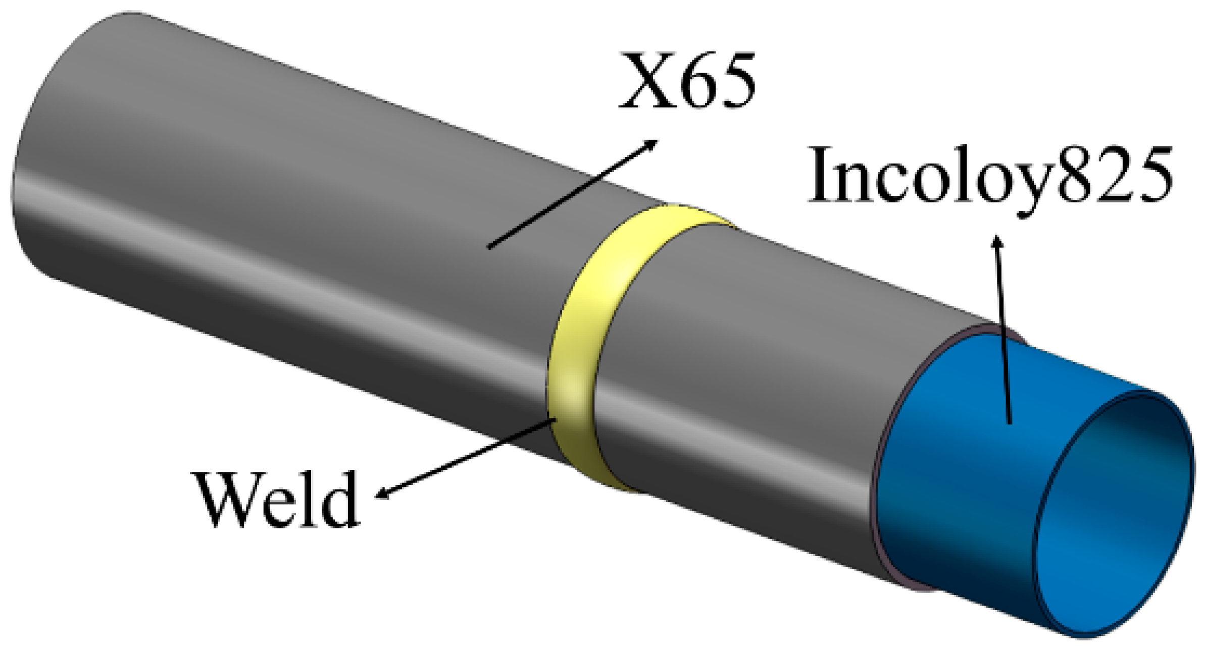
2.1. Experimental Material

The experimental material was Incoloy825/X65 bimetallic explosive welded composite pipe with a specification of φ610 mm × (22 + 3) mm, the base material was X65, and the cladding was Incoloy825, as shown in Figure 1. When selecting welding materials, Incoloy625 with high content of alloying element was selected in consideration of the element burning loss of filler metal in the welding process. The chemical composition of the cladding, base and weld metal is shown in Table 1.

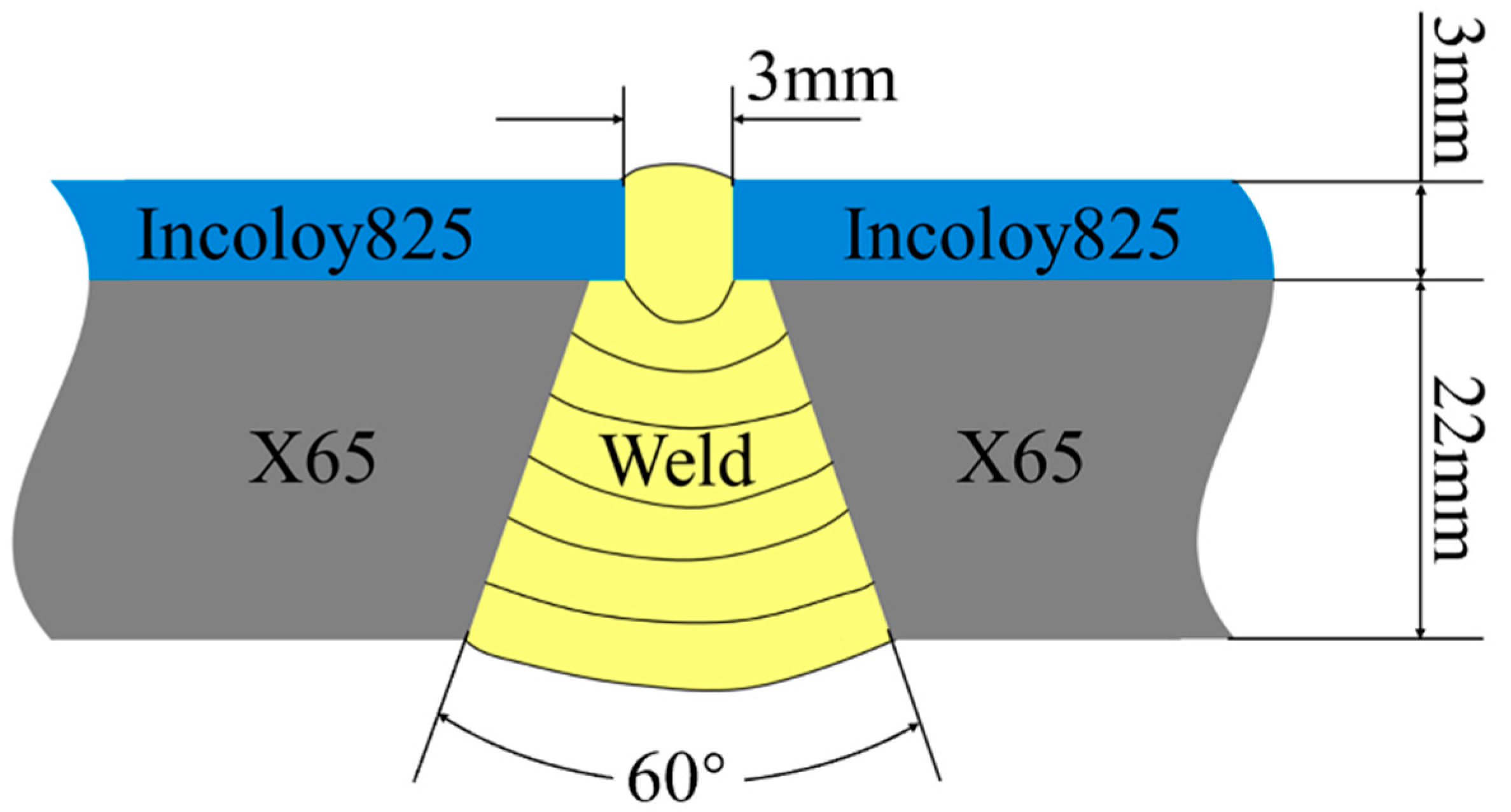
2.2. Welding Parameters
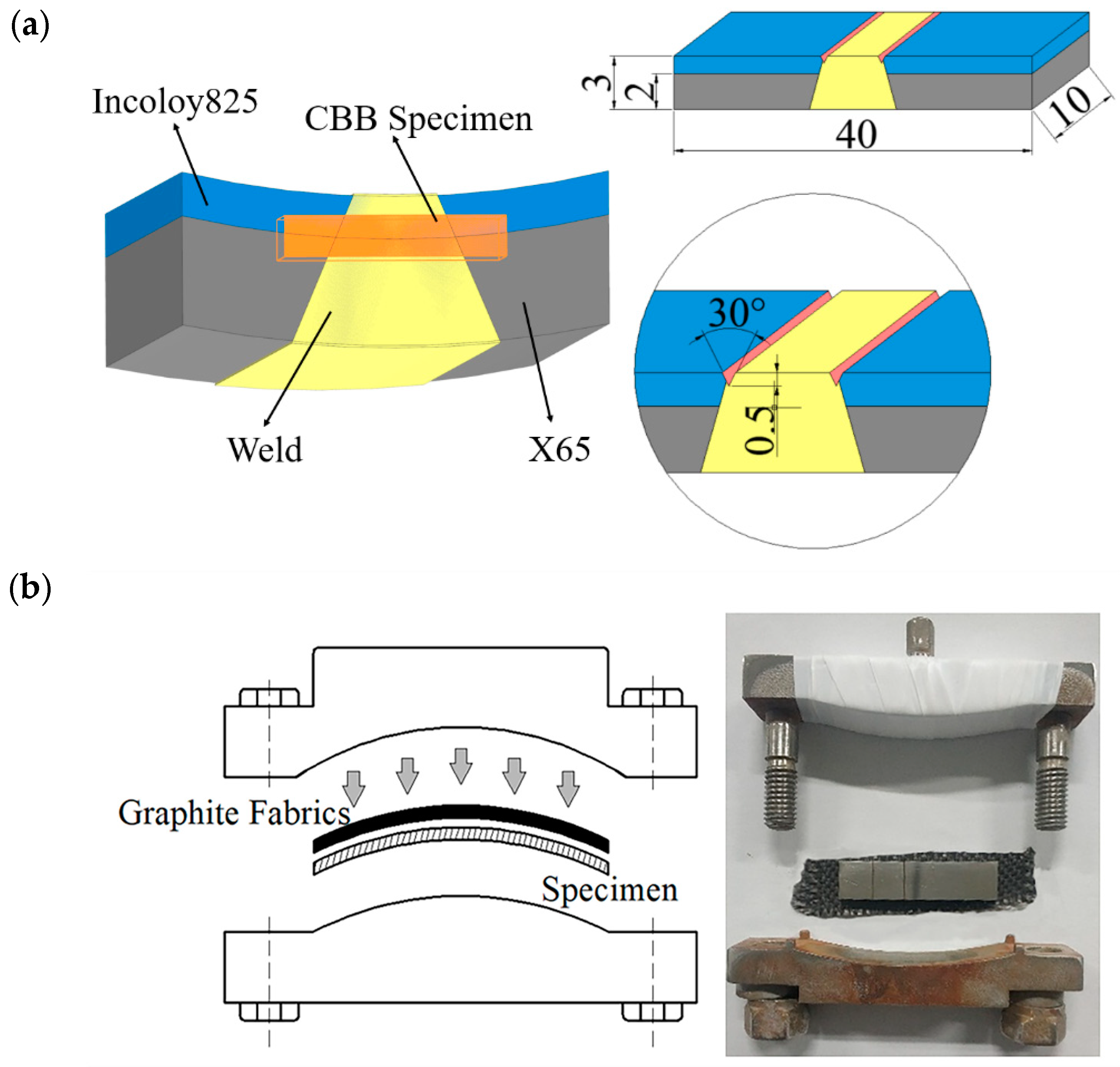
The cladding Incoloy825 used gas tungsten active welding (GTAW), and the base X65 used shielded metal arc welding (SMAW). The groove type was Y-shaped groove, the groove gap was 3 mm, and the groove angle was 60°. A total of 7 passes were required for multi-pass welding in the sequence from the cladding to the base. GTAW was used for the first pass of welding, and SMAW was used for the filling and covering passes, as shown in Figure 2. Referring to the standard NB/T 47015 to select welding parameters. The specific welding parameters are shown in Table 2.

2.3. CBB Test

CBB test is one of the commonly used methods to evaluate the SCC behavior of metal, and it belongs to the constant deformation method [18]. The sampling location of the CBB sample is shown in Figure 3a. The sample size was 40 mm × 10 mm × 3 mm, and there were six samples in total. Since the FB is the weak link of the welded joint, a V-shaped notch was opened at each of the two FB between the cladding and the weld to accelerate the crack propagation. The notch angle was 30°, and the height was 0.5 mm. As shown in Figure 3b, the upper and lower clamps were used to fix and bend the specimen to generate uniform strain on the surface of the specimen, and graphite fabrics were placed above the cladding to form gaps to accelerate the corrosion rate [19]. The corrosive medium of the test was NACE-0177 standard solution, namely saturated H2S deoxygenated distilled water solution containing 0.5% acetic acid. The solution was passed through N2 for 1 h to deoxygenate and then H2S was passed to saturation to simulate a H2S environment. The test period was 3600 h. After the test, the specimen was taken out, cleaned and cut longitudinally to analyze the corrosion behavior of the specimen.

2.4. Characterization Test

Optical microscope (OM, MDJ200, Chongqing Optec Instrument Co., Ltd. Chongqing, China) and scanning electron microscope (SEM, JSM-7200F, JEOL Ltd. Tokyo, Japan) were used to observe the microstructure and crack propagation path of the bimetallic composite pipe welded joint, Energy dispersive spectrometer (EDS, X-Mas50, Oxford Instruments Technology (Shanghai) Co., Ltd. Shanghai, China) was used to scan the element distribution at the intersection of the three zones and the crack tip before and after the CBB test to analyze the effect of element diffusion on crack initiation and propagation.
Electron backscatter diffraction (EBSD, Nordys Max3, Oxford Instruments Technology (Shanghai) Co., Ltd. Shanghai, China) was used to observe the microstructure at the intersection of three zones and the crack tip of the specimen. The relationship between the grain boundary and crack initiation and propagation was analyzed from the microscopic point of view, and the cause of crack initiation and propagation in the welded joint of bimetallic composite pipe was explored. The test acceleration voltage was 30 kV, the current was 13 nA and the step was 0.2 μm. Channel 5 software (5.12.74.0, Oxford Instruments NanoAnalysis, High Wycombe, UK) was used for data analysis.

3. Results and Discussion

3.1. Microstructure Analysis

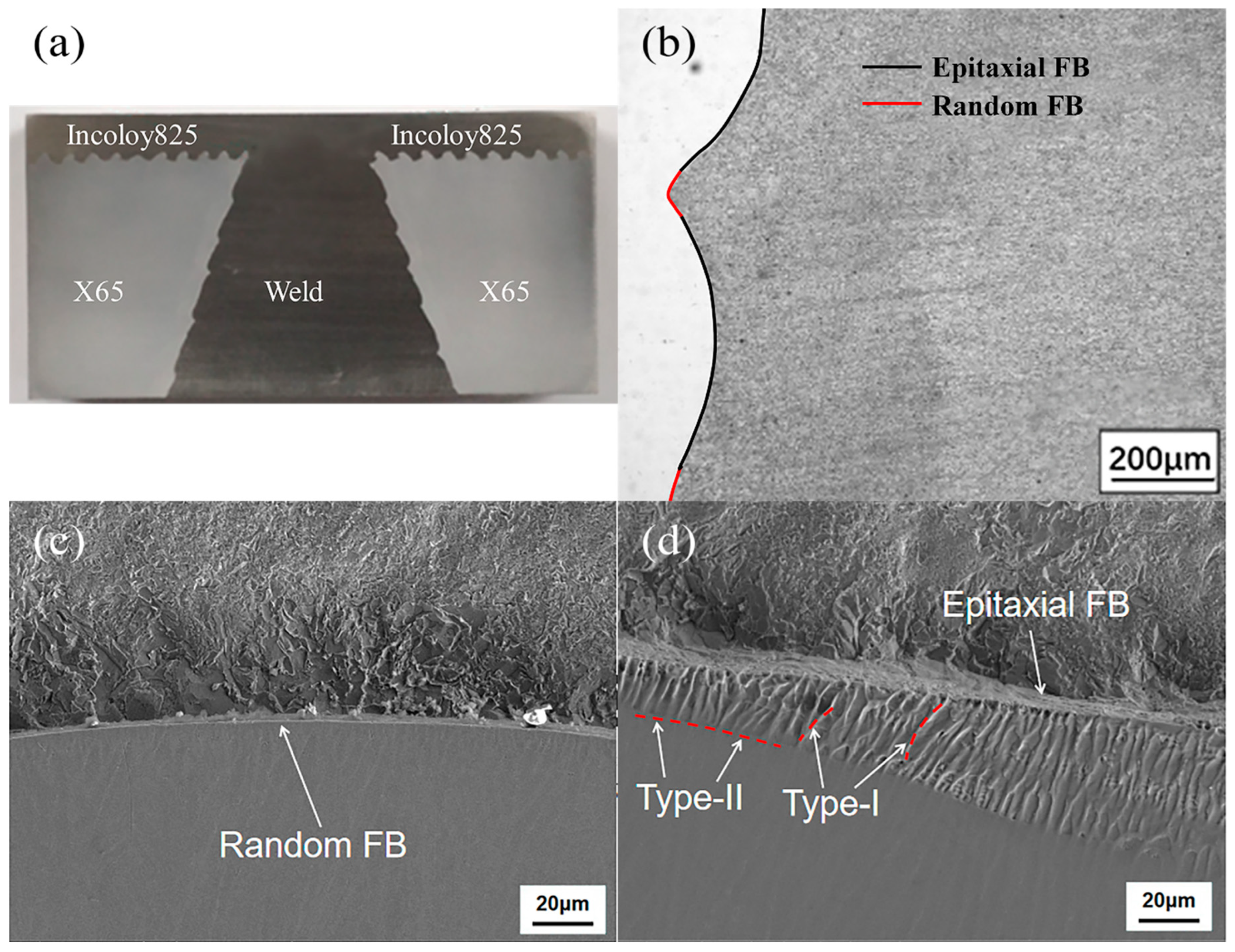
3.1.1. Microstructure Analysis of the Welded Joint

Figure 4a,b are the macroscopic schematic diagram and the microstructure diagram of the welded joint of the bimetallic composite pipe. It can be seen from Figure 4b that there are two types of FB, namely random FB (red) and epitaxial FB (black), which are distributed alternately along the interface. As shown in Figure 4c,d, the random FB is narrow and smooth and exists at the boundary corner of the weld pass, while the epitaxial FB is wide and straight and exists in the middle of the weld pass. As shown in Figure 4d, two types of grain boundaries, Type-I and Type-II, were observed in the partially melted zone (PMZ) of the epitaxial FB, which were perpendicular and parallel to the FB, respectively. These grain boundaries have high stress corrosion sensitivity, and provide a potential path for crack propagation [20,21,22].
Figure 5 is the inverse pole figure (IPF) diagram of the intersection of the three zones. It can be observed that the grains of X65 were relatively small, while Incoloy825 showed coarse equiaxed grains, and the weld microstructure was coarse columnar grains. There was a straight and continuous grain boundary parallel to the FB on the side of X65. The formation mechanism of this grain boundary is similar to that of Type-II grain boundary, which is formed due to the allotropic transformation of the dissimilar metal FB during the cooling process [15,23]. However, the difference is that the Type-II grain boundary was located on the side of the weld metal, while this grain boundary was located on the side of the base metal.

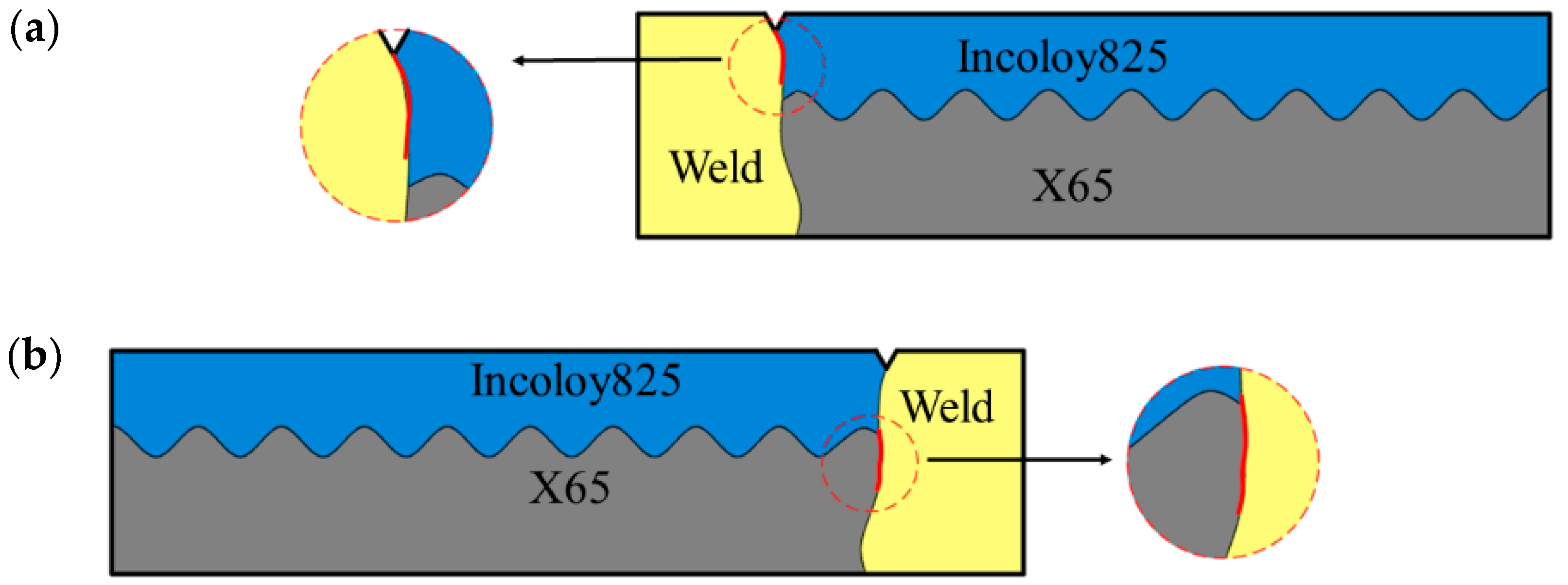
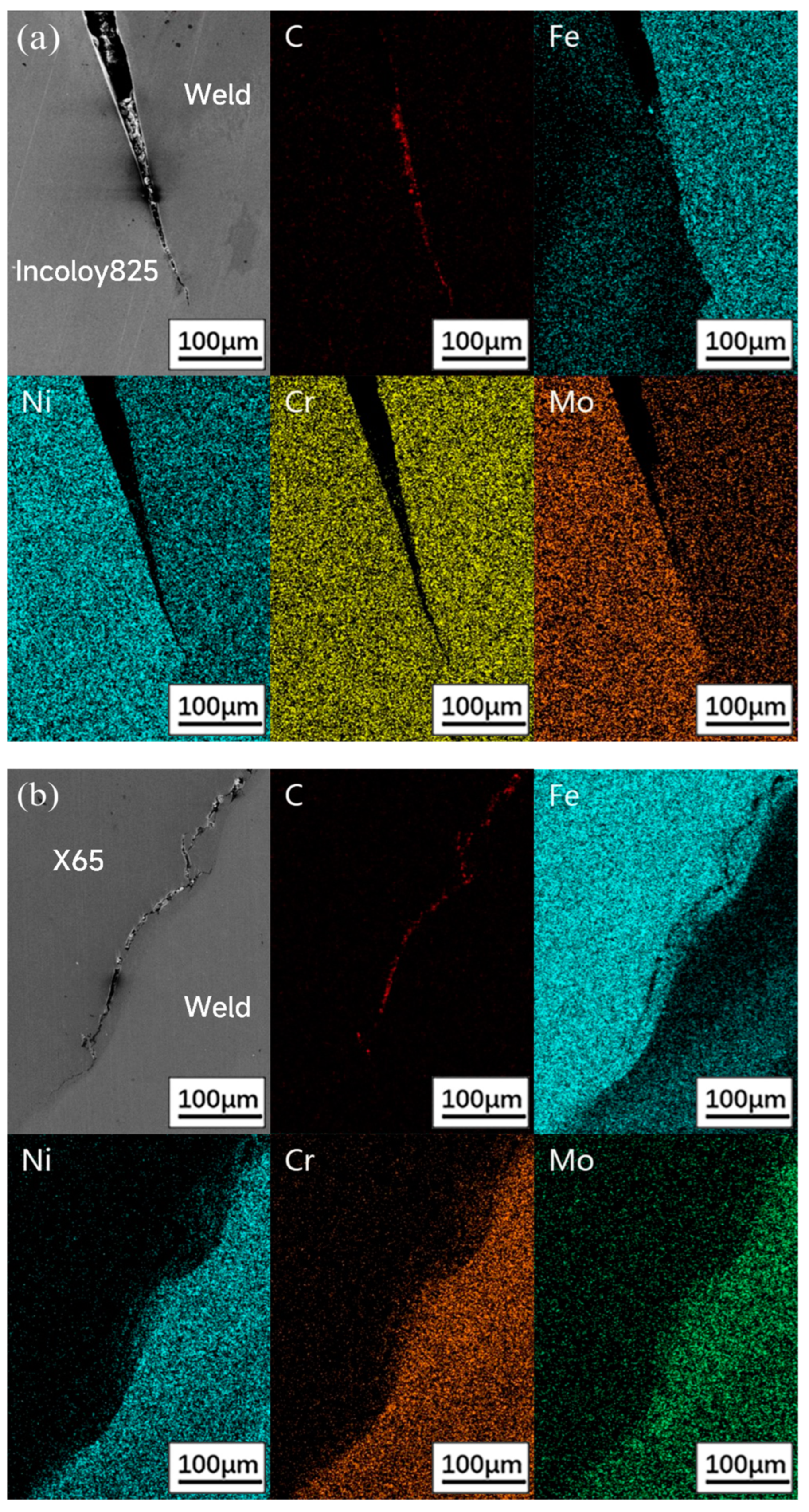
3.1.2. SCC Behavior Analysis

After the CBB test, two different types of cracks were found in the specimen, as shown in Figure 6a,b. Crack initiation positions were at the bottom of the V-shaped notch and the intersection of the three zones, respectively, which were denoted as crack 1 and crack 2, both of which expanded along the FB after initiating the crack.
The SEM diagrams of crack 1 and crack 2 are shown in Figure 7. Figure 7a is the overall view and the local magnification of the crack 1. The crack 1 initiated at the V-shaped notch, propagated along the FB between Incoloy825 and weld, and deflected at a larger defect and then continued to propagate along the FB. The crack tip was discontinuous and consisted of a large number of intermittent micro-pits. Figure 7b is the overall view and local magnification of crack 2. The crack 2 initiated from the intersection of the three zones and propagated along the FB between X65 and weld. When the Type-II-like grain boundary appeared on the X65 side, it deviated from the FB and propagated along the Type-II-like grain boundary. The type-II-like grain boundary provided a continuous channel for crack propagation.

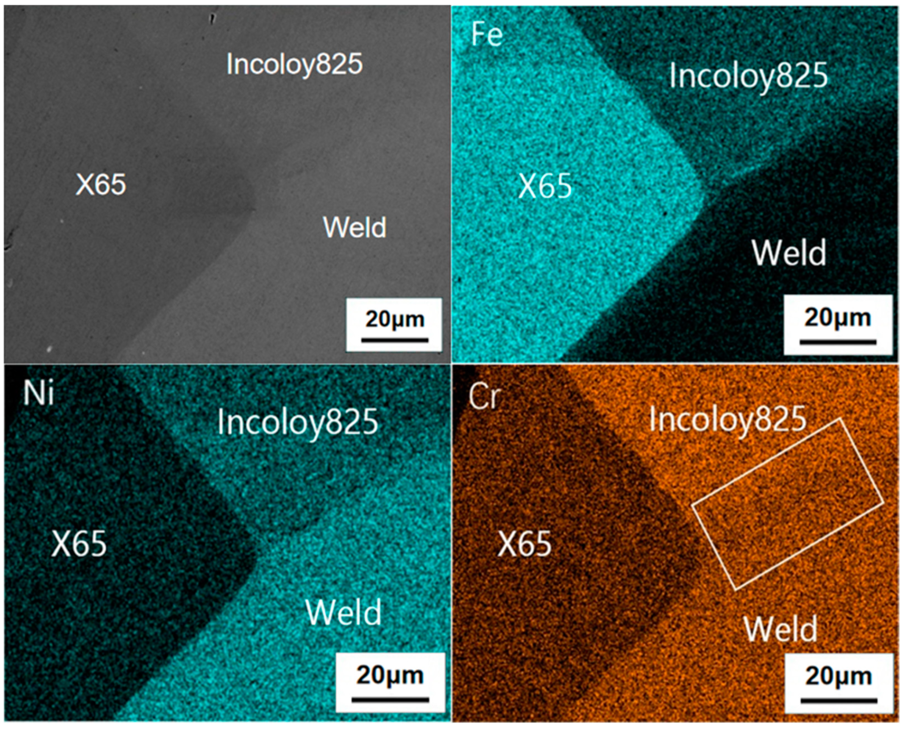
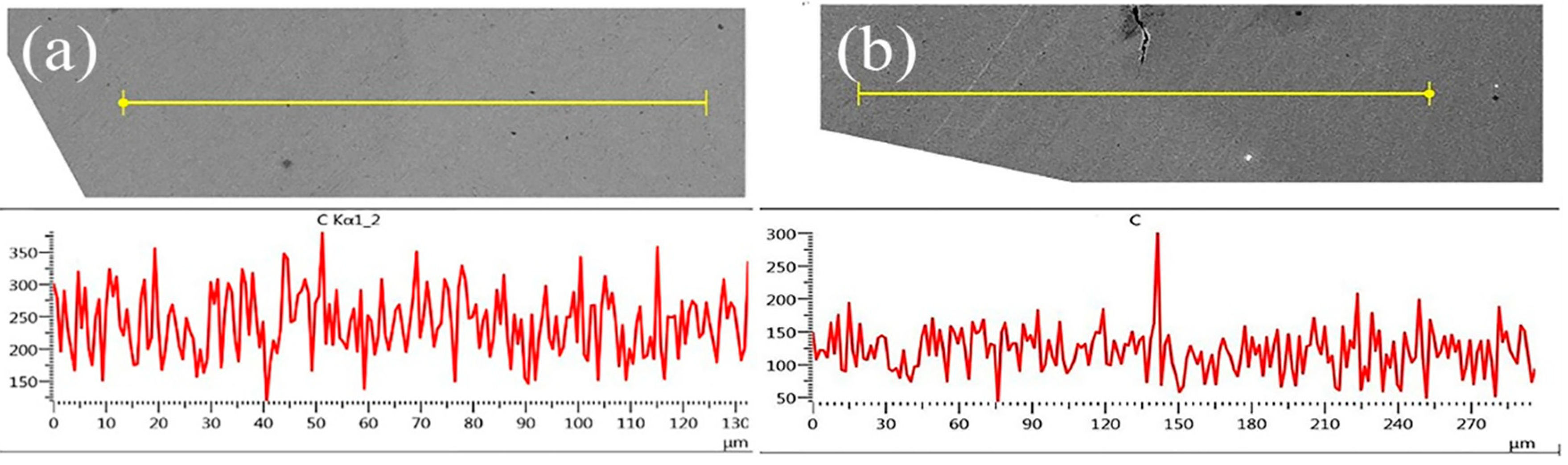
3.2. Element Diffusion Analysis

The element surface scanning at the intersection of the three zones is shown in Figure 8. At the intersection of the three zones, the element distribution of Fe, Ni and Cr elements were extremely uneven. The Ni and Cr elements that increase the potential of the metal electrode were concentrated in Incoloy825 and the weld, which was the area with less Fe element. At the boundary of each zone, there was a mutation in the distribution of elements, and the electrode potential of each element has a great difference, which was one of the reasons leading to crack initiation at the FB. By observing the surface distribution diagram of Cr element in Figure 8, there was a missing band of Cr element along the FB between Incoloy825 and weld. According to previous studies, it was due to the supersaturated carbon diffused to the FB and formed Cr23C6 with Cr, which precipitated at the grain boundary [24], while the Cr diffusion speed inside the grain was slow and there was no time to diffuse to the FB. Therefore, Cr deficiency occurred near the FB, and the loss of beneficial elements Ni and Cr at the FB was an important factor leading to the crack initiation and propagation on the FB.
The element surface scanning results of two types of crack tips are shown in Figure 9. The Fe element distribution shows that the Fe content in the area of the FB decreased obviously, because of the anodic dissolution of Fe atoms near the FB: Fe → Fe2+ + 2e. Fe atoms had higher surface energy and were easy to activate to lose electrons. The content of C element at the crack tip was very high, and the elements distribution besides the crack is uneven. Figure 10a,b show the C content at the FB in front of the crack tip before and after CBB test, respectively. The C content increased at the FB in front of the crack tip, while the C content was evenly distributed before the CBB test. Combined with the analysis [25], metal carbides had been precipitated in front of the crack tip under the action of H2S, which led to the embrittlement of the crack tip. Additionally, the grain boundary embrittlement was one of the inducements of stress corrosion cracking.

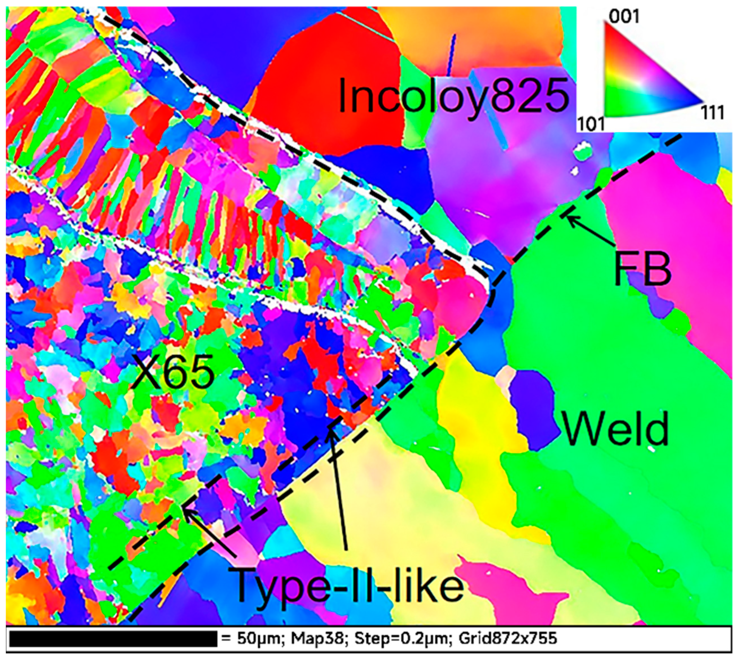
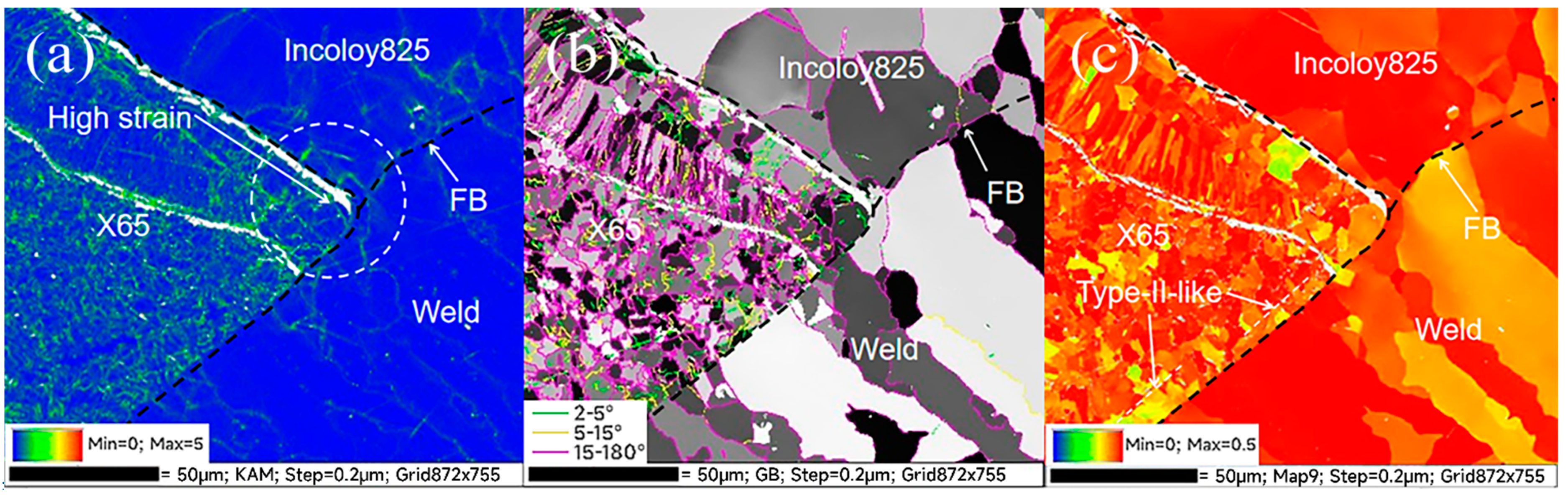
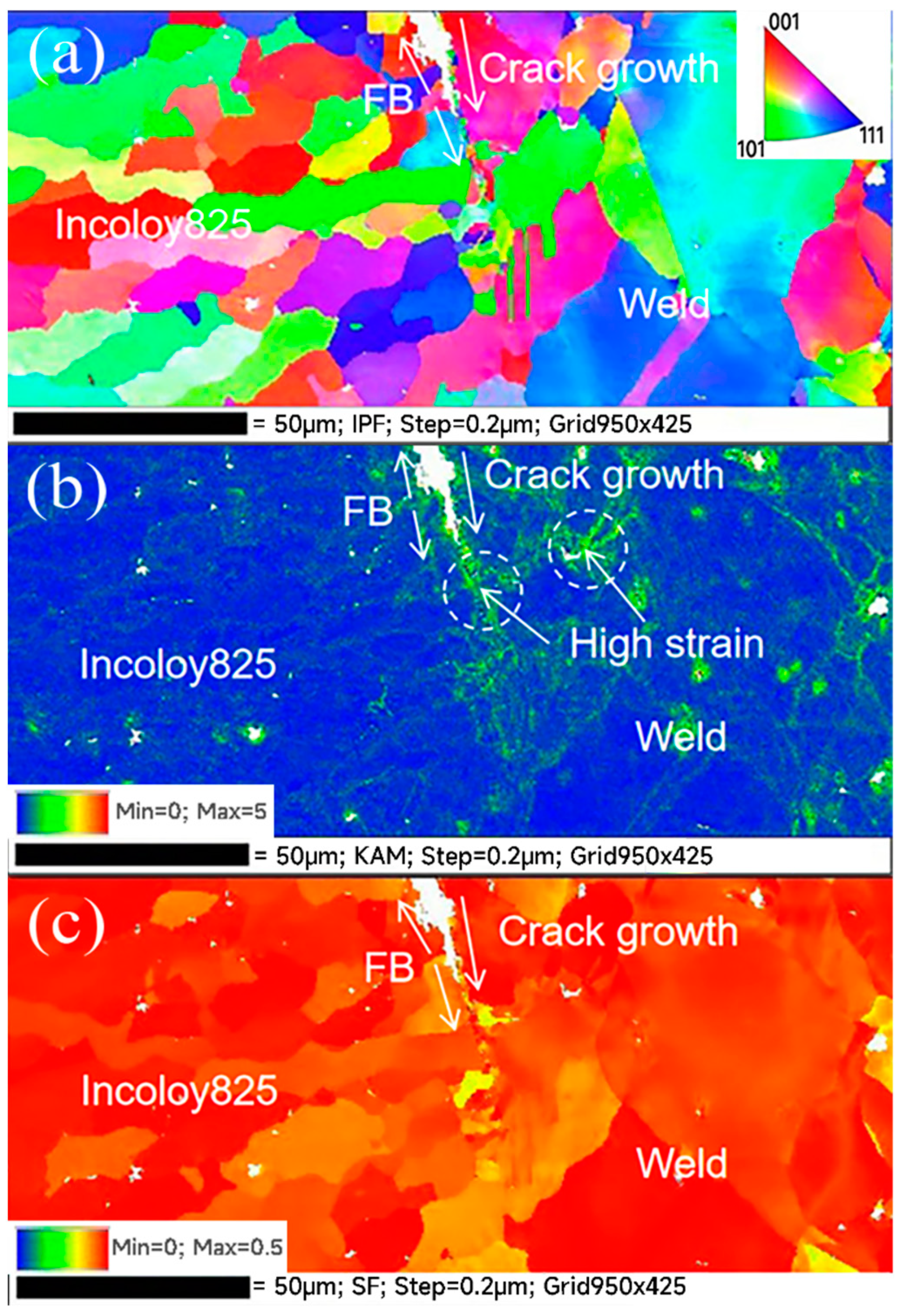
3.3. EBSD Results Analysis

Figure 11a is the KAM (kernel average misorientation) diagram at the intersection of the three zones, which is used to characterize the residual strain in the material. It can be seen that there was a high residual strain at the interface of X65/Incoloy825 and the FB, and the residual strain at the intersection of the three zones was the relatively concentrated. Figure 11b is the grain boundary angle distribution at the intersection of the three zones. Green represents the grain boundary of 2~5°, yellow represents the grain boundary of 5~15°, and purple represents the grain boundary greater than 15°. It is generally believed that grain boundaries greater than 10° are high angle grain boundaries and belong to high energy grain boundaries. Compared with low angle grain boundaries, the binding force between atoms is weaker [26]. As shown in Figure 11b, a large number of high angle grain boundaries existed on the FB, so crack 1 and crack 2 propagated along the FB. Figure 11c is the Schmid factor diagram at the intersection of the three zones, representing the degree of difficulty to start the slip system of the same type. It can be seen that the Schmid factor value of grains at the FB was large, which indicated that grains at the FB were prone to slip, and crack was prone to occur when under constant stress. In addition, there was a continuous Type-II-like grain boundary about 10 μm parallel to the left of the FB. According to the Schmid factor diagram, along the Type-II-like grain boundary, the Schmid factor value difference between grains was large. When the crack propagated along the FB to this point, it would continue to propagate along the straight grain boundary because it found an easier path to propagate. Therefore, the grain boundary intersection was the initial point of crack bifurcation and bending, and the change of grain boundary structure can explain the deflection phenomenon in crack propagation.
Figure 12a is the IPF diagram of the crack tip of the FB. The grains of the weld were coarse and massive, while the grains of Incoloy825 were elongated, all of which were austenite. The grain refinement in front of the crack may be due to the large strain at the crack tip, which presented different grain orientations. Figure 12b is the KAM diagram of the crack tip of the FB. The strain increased significantly within about 30 μm in front of the crack tip, and the high strain zone presented a dendritic distribution along the grain boundary and there was serious strain concentration in the weld. Figure 12c is the Schmid factor diagram of the crack tip. The Schmid factor at the crack tip was small and the strain concentration was obvious, which provided conditions for crack propagation.
The cracks that appeared in the specimen after the CBB test were analyzed. Crack 1 and crack 2 initiated from the notch and the intersection of the three zones, respectively. After the initiation, cracks first propagated along the FB, and then deflected toward the defect and the Type-II-like grain boundary. Finally, the crack tips were pitted and passivated, thus stopping the expansion. The stress and strain were concentrated at the bottom of the notch, the uneven distribution of Fe, Ni and Cr at the interface led to a mutation in the electrode potential, and the metal on the notch surface reacted with H2S directly, so cracking was caused under the action of external stress, which belonged to anodic dissolved stress corrosion cracking. At the intersection of the three zones, there were large residual strain, Cr deficiency, high SCC sensitivity and the influence of hydrogen generated during the corrosion process of crack 1. The synergistic effect of strain concentration, grain boundary embrittlement and hydrogen embrittlement promoted the initiation of cracks. The microstructure near the FB was complex, and there were random FB and epitaxial FB. There were two types of grain boundaries Type-I and Type-II in the epitaxial FB. The EBSD test results show that these two grain boundaries belonged to high angle grain boundaries. The bonding force was weak, and the SCC sensitivity was high, so the crack propagated along the FB after crack initiation. There was a Type-II-like grain boundary on the X65 side about 10 μm parallel to the FB, and the Schmid factor was large. When the crack propagated along the FB to this point, the crack deflected and continued to propagate along the Type-II-like grain boundary because it found a path that was easier to propagate. The crack tip was composed of a large number of discontinuous pits, and metal carbides precipitated in front of the crack tip. It was speculated that the crack tip was pitted and passivated, thus stopping the propagation.

4. Conclusions

The welded joint of the Incoloy825/X65 bimetallic composite pipe showed two types of cracks after the CBB test. The conclusions of crack initiation and propagation are as follows:
(1)
Crack 1 initiated from the notch. The main reasons for cracking are the stress and strain concentration. The mutation of the electrode potential was led by the uneven distribution of Fe, Ni and Cr at the interface and the direct reaction between metal and H2S. The mechanism is the anodic dissolved stress corrosion cracking.
(2)
Crack 2 initiated from the intersection of the three zones, where there was residual strain concentration, lack of Cr and the effect of hydrogen generated by crack 1 during the corrosion process on the intersection of the three zones. The synergistic effect of strain concentration, grain boundary embrittlement and hydrogen embrittlement promoted the initiation of cracks.
(3)
The welded joint has high angle grain boundaries, Type-I, Type-II and the Type-II-like, which had high SCC sensitivity and provided intergranular channels for crack propagation. After initiation, the two kinds of cracks propagated along the FB and the Type-II-like boundary, and the crack tips were pitted and passivated, thus stopping the propagation.

Author Contributions

Conceptualization, B.W. and J.X.; Methodology, L.O. and J.X.; Validation, B.W. and E.L.; Investigation, L.O., J.X. and P.H.; Writing—Original Draft Preparation, B.W., L.O. and J.X.; Writing—Review and Editing, P.H., E.L. and B.Y. All authors have read and agreed to the published version of the manuscript.

Funding

The authors gratefully acknowledge the support from the Fundamental Research Funds for the Central Universities (18CX05002A) and the Natural Science Foundation of Shandong Province (ZR2019MEE108).

Data Availability Statement

Not applicable.

Conflicts of Interest

The authors declare no conflict of interest.

References

  1. Fragiel, A.; Serna, S.; Malo-Tamayo, J.; Silva, P.; Campillo, B.; Martínez-Martínez, E.; Cota, L.; Staia, M.; Puchi-Cabrera, E.S.; Perez, R. Effect of microstructure and temperature on the stress corrosion cracking of two microalloyed pipeline steels in H2S environment for gas transport. Eng. Fail. Anal. 2019, 105, 1055–1068. [Google Scholar] [CrossRef]
  2. Carneiro, R.A.; Ratnapuli, R.C.; Lins, V. The influence of chemical composition and microstructure of API linepipe steels on hydrogen induced cracking and sulfide stress corrosion cracking. Mater. Sci. Eng. A 2003, 357, 104–110. [Google Scholar] [CrossRef]
  3. Wen, X.; Bai, P.; Luo, B.; Zheng, S.; Chen, C. Review of recent progress in the study of corrosion products of steels in a hydrogen sulphide environment. Corros. Sci. 2018, 139, 124–140. [Google Scholar] [CrossRef]
  4. Ma, H.; Cheng, X.; Li, G.; Chen, S.; Quan, Z.; Zhao, S.; Niu, L. The influence of hydrogen sulfide on corrosion of iron under different conditions. Corros. Sci. 2000, 42, 1669–1683. [Google Scholar] [CrossRef]
  5. Song, C.; Ling, J. Effects of H2S Partial Pressure on Stress Corrosion Cracking of Nickel-based Alloy G3. Corros. Prot. Petrochem. Ind. 2020, 37, 21–23. [Google Scholar]
  6. Zhao, X.H.; Han, Y.; Bai, Z.Q.; Wei, B. The experiment research of corrosion behaviour about Ni-based alloys in simulant solution containing H2S/CO2. Electrochim. Acta 2011, 56, 7725–7731. [Google Scholar] [CrossRef]
  7. Alekseeva, E.; Galata, L.; Lapechenkov, A.; Kovalev, M. Evaluation of Corrosion Resistance of Nickel-based Alloy EP718 for use in Hydrogen Sulphide Containing Environment. E3S Web Conf. 2021, 225, 03001. [Google Scholar] [CrossRef]
  8. Lu, C.-H. PWHT welding procedure for nickel alloy cladding pipe. Weld. Technol. 2021, 49, 51–54. [Google Scholar]
  9. Wang, B.; Lei, B.-B.; Wang, W.; Xu, M.; Wang, L. Investigations on the crack formation and propagation in the dissimilar pipe welds involving L360QS and N08825. Eng. Fail. Anal. 2015, 58, 56–63. [Google Scholar] [CrossRef]
  10. Wang, H.T.; Wang, G.Z.; Xuan, F.Z.; Tu, S.T. An experimental investigation of local fracture resistance and crack growth paths in a dissimilar metal welded joint. Mater. Des. 2013, 44, 179–189. [Google Scholar] [CrossRef]
  11. Jang, C.; Lee, J.; Kim, J.S.; Jin, T.E. Mechanical property variation within Inconel 82/182 dissimilar metal weld between low alloy steel and 316 stainless steel. Int. J. Press. Vessel. Pip. 2008, 85, 635–646. [Google Scholar] [CrossRef]
  12. Blouin, A.; Chapuliot, S.; Marie, S.; Niclaeys, C.; Bergheau, J.-M. Brittle fracture analysis of Dissimilar Metal Welds. Eng. Fract. Mech. 2014, 131, 58–73. [Google Scholar] [CrossRef]
  13. Celin, R.; Tehovnik, F. Degradation of a Ni-Cr-Fe alloy in a pressurised-water nuclear power plant. Mater. Technol. 2011, 45, 151–157. [Google Scholar]
  14. Yoshida, K.; Kojim, M.; Iida, M.; Takahashi, I. Fracture toughness of weld metals in steel piping for nuclear power plants. Int. J. Press. Vessel. Pip. 1990, 43, 273–284. [Google Scholar] [CrossRef]
  15. Wang, W.; Lu, Y.; Ding, X.; Shoji, T. Microstructures and microhardness at fusion boundary of 316 stainless steel/Inconel 182 dissimilar welding. Mater. Charact. 2015, 107, 255–261. [Google Scholar] [CrossRef]
  16. Nelson, T.W.; Lippold, J.C.; Mills, M.J. Nature and evolution of the fusion boundary in ferritic–austenitic dissimilar weld metals, part 2: On-cooling transformations. Weld. J. 2000, 79, 267S–277S. [Google Scholar]
  17. Hou, J.; Peng, Q.; Takeda, Y.; Kuniya, J.; Shoji, T. Microstructure and stress corrosion cracking of the fusion boundary region in an alloy 182-A533B low alloy steel dissimilar weld joint. Corros. Sci. 2010, 52, 3949–3954. [Google Scholar] [CrossRef]
  18. Nishikawa, S.; Horii, Y.; Ikeuchi, K. Effect of Chromium Content on Stress Corrosion Cracking Susceptibility of Shielded Metal Arc Weld Metals for 600 Type Alloy in High Temperature Pressurized Pure Water. Weld. Int. 2013, 27, 450–459. [Google Scholar] [CrossRef]
  19. Mayuzumi, M.; Ishiyama, N.; Mizutani, Y.; Tani, J.-I.; Kako, K. Incubation Time of Stress Corrosion Cracking for Type 316L and Type 316 Stainless Steels by CBB Method in High Temperature Water. Corros. Eng. 2008, 57, 230–234. [Google Scholar] [CrossRef]
  20. Nelson, T.W.; Lippold, J.C.; Mills, M.J. Nature and evolution of the fusion boundary in ferritic-austenitic dissimilar weld metals. Part 1—Nucleation and growth. Weld. J. 1999, 78, 329s–337s. [Google Scholar]
  21. Lu, Z.; Shoji, T.; Meng, F.; Xue, H.; Qiu, Y.; Takeda, Y.; Negishi, K. Characterization of microstructure and local deformation in 316NG weld heat-affected zone and stress corrosion cracking in high temperature water. Corros. Sci. 2011, 53, 1916–1932. [Google Scholar] [CrossRef]
  22. Ghosh, M.; Santosh, R.; Das, S.K.; Das, G.; Mahato, B.; Korody, J.; Kumar, S.; Singh, P.K. Effect of Structural Heterogeneity on In Situ Deformation of Dissimilar Weld Between Ferritic and Austenitic Steel. Metall. Mater. Trans. A 2015, 46, 3555–3568. [Google Scholar] [CrossRef]
  23. Nelson, T.W.; Lippold, J.C.; Mills, M.J. Investigation of boundaries and structures in dissimilar metal welds. Sci. Technol. Weld. Join. 1998, 3, 249–255. [Google Scholar] [CrossRef]
  24. Hou, J.; Peng, Q.; Shoji, T.; Wang, J.; Ke, W.; Han, E. Study of Microstructure and Stress Corrosion Cracking Behavior in Welding Transition Zone of Ni-Based Alloys. Acta Metall. Sin. 2010, 46, 1258–1266. [Google Scholar] [CrossRef]
  25. Jiao, Y.; Zheng, W.; Kish, J.R. Stress corrosion cracking susceptibility of thermally-aged Type 310S stainless steels in supercritical water. Corros. Sci. 2018, 135, 1–11. [Google Scholar] [CrossRef]
  26. Dong, L.; Peng, Q.; Xue, H.; Han, E.-H.; Ke, W.; Wang, L. Correlation of microstructure and stress corrosion cracking initiation behaviour of the fusion boundary region in a SA508 Cl. 3-Alloy 52M dissimilar weld joint in primary pressurized water reactor environment. Corros. Sci. 2017, 132, 9–20. [Google Scholar] [CrossRef]
Figure 1. Schematic diagram of X65/Incoloy825 bimetallic composite pipe.
Metals 12 00632 g001
Figure 2. The groove form.
Metals 12 00632 g002
Figure 3. Schematic diagram of CBB test: (a) schematic diagram of CBB specimen(unit: mm); (b) diagram of experimental apparatus.
Metals 12 00632 g003
Figure 4. Microstructure diagram of the welded joint of the bimetallic composite pipe: (a) macroscopic schematic diagram; (b) microstructure diagram; (c) random FB; (d) epitaxial FB.
Metals 12 00632 g004
Figure 5. The IPF diagram of the intersection of three zones.
Metals 12 00632 g005
Figure 6. Schematic diagram of crack location: (a) crack 1; (b) crack 2.
Metals 12 00632 g006
Figure 7. SEM diagram of crack 1 and crack 2: (a) overall view and local magnification (A–C) of crack 1; A–C diagram represent the local magnification of three places A, B and C, respectively; (b) overall view and local magnification of crack 2.
Metals 12 00632 g007
Figure 8. The element surface scanning at the intersection of three zones.
Metals 12 00632 g008
Figure 9. The element surface scanning at tips of crack 1 and crack 2: (a) crack 1; (b) crack 2.
Metals 12 00632 g009
Figure 10. The element line scanning at the crack tip: (a) before CBB test; (b) after CBB test.
Metals 12 00632 g010
Figure 11. EBSD results at the intersection of the three zones: (a) KAM diagram; (b) grain boundary angle distribution; (c) Schmid factor diagram.
Metals 12 00632 g011
Figure 12. EBSD results of crack tip: (a) IPF diagram; (b) KAM diagram; (c) Schmid factor diagram.
Metals 12 00632 g012
Table 1. Chemical compositions of Incoloy825, X65 and weld (wt.%).
MaterialCSiMnPSNiCrMoCuTiFe
X650.080.260.980.060.100.290.240.040.240.0097.71
Incoloy8250.010.490.730.050.0137.222.233.913.110.7032.29
Weld0.030.460.320.060.1059.6220.339.320.330.359.08
Table 2. Welding parameters.
Pass
(Welding Process)
Filler MetalDiameter
(mm)
Power PolarityCurrent
(A)
Voltage
(V)
Weld Speed
(cm/min)
Gas Flow (L/min)
FrontBack
Root Pass
(GTAW)
ERNiCrMo-32.4DC
Straight Polarity
90~1209~125~87~1315~25
Filling and Covering Pass
(SMAW)
ENiCrMo-33.2DC
Reverse Polarity
80~9020~235~77~1315~25
Publisher’s Note: MDPI stays neutral with regard to jurisdictional claims in published maps and institutional affiliations.

