Article

Multipoint Forming Using Hole-Type Rubber Punch

by
Abror Tolipov
1,
Hany Hassanin
2,*,
Mahmoud Ahmed El-Sayed
3,
Hossam Mohamed Eldessouky
3,
Naser A. Alsaleh
4,
Adel Khalid Alfozan
4,
Khamis Essa
1 and
Mahmoud Ahmadein
4,5
1
School of Engineering, University of Birmingham, Birmingham B15 2TT, UK
2
School of Engineering, Technology, and Design, Canterbury Christ Church University, Canterbury CT11QU, UK
3
Department of Industrial Engineering, Arab Academy for Science Technology and Maritime, Alexandria 21599, Egypt
4
College of Engineering, Imam Mohammad Ibn Saud Islamic University, Riyadh 11564, Saudi Arabia
5
Department of Production Engineering and Mechanical Design, Tanta University, Tanta 31512, Egypt
*
Author to whom correspondence should be addressed.
Metals 2022, 12(3), 491; https://doi.org/10.3390/met12030491
Submission received: 28 January 2022 / Revised: 26 February 2022 / Accepted: 7 March 2022 / Published: 14 March 2022
(This article belongs to the Topic Advanced Forming Technology of Metallic Materials)

Abstract

:
Reconfigurable multipoint forming is a flexible sheet forming technique aimed at customised sheet metal products. However, one drawback of multipoint forming is the cost and time needed to set up and align the upper and lower pin matrices. This study introduces an optimisation study of a novel hole-type rubber punch replacing the top pin matrix of multipoint incremental forming, aiming to reduce pins setting up and alignment complexity and time. Finite element modelling and design of experiments were used to investigate the effect of hole-type rubber punch configuration such as hole size, hole type, and the compression ratio on the wrinkling, thickness variation, and shape deviation. This research shows that the most significant process parameter in all responses was the hole size. The compression ratio of the material was found to be insignificant in wrinkling and shape deviation. The hole-type rubber punch parameters were found to be a hole size of 9 mm, circular hole type, and a compression ratio of 75%. This experimentally resulted in an improved parts wrinkling of 80%, when compared to using solid rubber punch, with the added benefits of reduction of the cost and time needed to set up and align the pin matrices.

1. Introduction

Conventional sheet metal forming techniques, especially deep drawing, are widely used to produce 3D components from sheet metal blanks for household, automotive and aerospace applications. However, the high tooling cost causes them to be economical for mass production only. In addition, the shortened lead time and product life cycle and the increased demand for customisation create additional challenges to sheet metal forming manufacturers [1,2,3,4,5]. Other manufacturing technologies, such as computer numerical control (CNC) or additive manufacturing (AM), are incapable of meeting the mass production strategies as well as the processing and the working requirements of sheet metal products compared to deep drawing technology [6]. Flexible manufacturing technologies, such as multipoint forming, offer the potential to easily adapt rapid changes in the design and quantity of sheet metal production [7,8,9,10]. Multipoint forming is one of the key elements of the make-to-order approach that provides industries with flexibility and speed. It uses a set of adjustable pins in the lower and upper matrices to create point-based dies, providing it with sufficient flexibility to produce customised products without designing and manufacturing new dies. However, setting up and aligning those pins is significantly time-consuming [11,12,13]. Multipoint forming has been significantly progressed as a flexible manufacturing process that offers the ability to control its associated process defects such as wrinkling, dimpling, and springback [14,15,16,17]. Elastomer materials, such as polyurethane, have been widely used in conventional and flexible sheet metal forming. The use of elastomer pads between the lower and upper dies has been found to reduce the time needed for the alignment or to match interchanged dies. In addition, they were shown to protect the metal surface from scratches usually resulting from the direct contact of dies. Several investigations were introduced on sheet metal forming using solid tools with elastomer pads for manufacturing different geometries [11,18]. One of the early studies that examined the use of the rubber dies’ process was carried out by Browen and Battikha [11]. In this work, the authors investigated the forming process’s capability and introduced an approach for the adjustment of process settings to ensure a defect-free product. Lee et al. [19] investigated the use of various rubber-based forming techniques to produce tubes made of aluminium and steel through using elastomer materials. Their study showed that the hardness of the elastomer materials was a crucial property affecting the bend radii. Quadrini et al. [20] also confirmed that high hardness rubber materials produced better quality thin aluminium products. Another study by Chen and co-authors [21] investigated the effect of rubber-based sheet metal forming variables such as the compression ratio and forming speed on the properties of the deformed part. Their study suggested that the spring-back effect of flanging in the rubber-based forming method was lower than when using the conventional stamping method [21].
Paunoiu et al. [22] found that the localised deformation in the metal sheet was significantly influenced by the pins-sheet contact points. Hence, they proposed using rubber cushions between the pins and the workpiece to enhance the surface quality and eliminate sheet thinning. Similar studies were introduced by Quan et al. [23], and Zareh-Desari et al. [24], which demonstrated the beneficial effect and concluded the presence of employing the application of the elastic cushions for minimising the dimpling defect and improving the accuracy of the formed products. Essa et al. [18] investigated the use of variable thickness waffle-type rubber cushions in multipoint forming with various thicknesses in multipoint forming. Their results suggested that the maximum cushion thickness and the pins profiles were the most significant factors influencing the wrinkling, thickness variation, and peak shape deviation [18].
A polyurethane rubber die with different hardness, thickness, and shapes was used to form different steel cup shapes. Numerical and experimental results showed that the forming load increases with increased rubber die hardness while it decreases with increased rubber die thickness [25]. Belhassen et al. compared the use of rubber punch or die in sheet metal forming. They suggested that using rubber die instead of rubber punch might form parts without micro cracks and necking due to the localized severe deformation that can lead to fracture of the sheet metal [26]. In a recent study, a novel two-step channel was formed by the use of rubber pad pressing. Different geometrical parameters such as the channel width, depth ratio, edge fillet, and second-step shape were studied. The authors found that the channels formed by convex mould were better than those formed by the use of a concave one [27]. The same research group extended their study and managed to use the two-step approach to manufacture sheet metal with micro-grooves [28].
Literature showed the promising potential of using rubber pad forming as a robust sheet metal forming tool. However, they are all based on conventional sheet metal forming. Elghawail et al. [29] introduced a new concept of replacing the upper die in a multipoint forming process with a thick rubber cushion to produce sheet metal products with about 50% reduction in the cost and setup time. The authors used a polyurethane block with a shore hardness of A90 as the upper punch combined with a reconfigurable lower multipoint forming die. The proposed solid polyurethane punch was found to be efficient in reducing the springback and wrinkling of the formed sheet [29]. However, no studies were found using hole-type rubber punch to replace the reported solid punch. Additionally, no studies were conducted to identify the optimal configuration rubber punches for multipoint forming. In this work, a hole-type rubber punch was used and optimised to replace the top solid punch. Finite element analysis and design of experiment’s approaches were used to investigate different process parameters, typically hole size, shape, and punch compression ratio, on the characteristics of the deformed parts such as wrinkling, thickness variation, and shape deviation. The process parameters have then been optimised towards eliminating defects in the final multipoint forming product.

2. Experimental and Methods

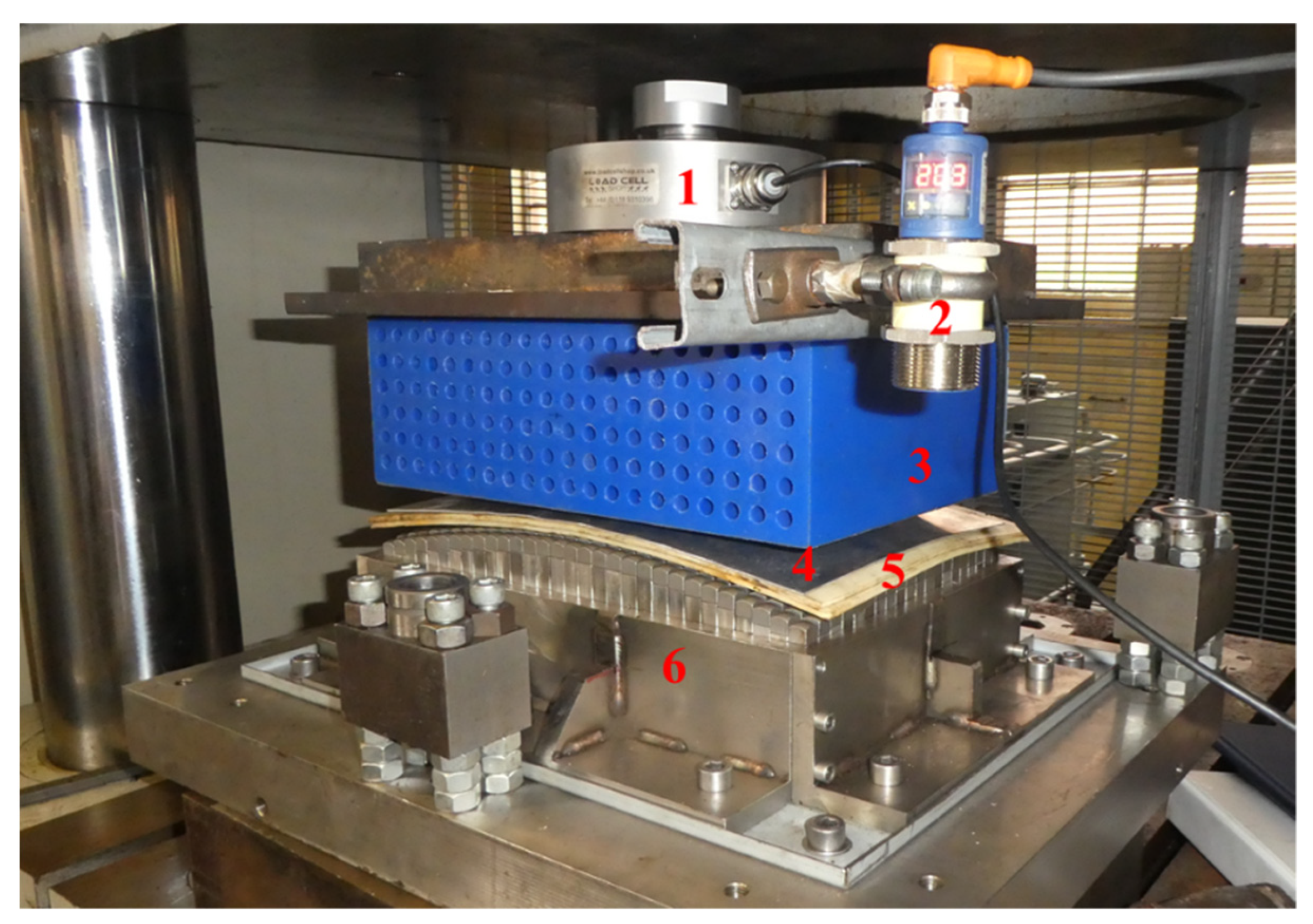
2.1. Experimental Setup

The hole-type rubber punch multipoint forming setup used to produce doubly curved panels is shown in Figure 1. The setup consists of a Polyurethane upper hole-type punch and a lower set of 30 × 20 pin matrix, which was adjusted to create the die for producing the desired curved panels, an elastic cushion, and a sheet metal as a workpiece. The sheet metal used in this was DC05 steel (chemical composition, wt. %: C 0.06% max, Mn 0.35% max, P 0.025% max, S 0.025% max and Fe balance), with a length of 153 mm, a width of 102 mm, and a thickness of 1. A rubber punch, with dimensions of 153 mm × 102 mm × 100 mm and with various hole shapes and dimensions, was placed on the top, replacing the upper pin matrix. The cube pins were 10 mm × 10 mm × 10 mm in dimension and with a spherical curvature of 10 mm diameter and a separation distance of 0.25 mm, see Figure 2a of the lower pint matrix. The sheet blank was placed between the hole-type rubber punch and the rubber cushion which was used to reduce the dimpling effect on the surface of the deformed product. The setup also includes force cell to record the force profile of the punch and a displacement sensor to measure the displacement of the punch movement, which will be used when calculating the compression ratio. A FARO Edge 3D scanner (Artec 3D, Birmingham, UK) fitted with Geomagic@ software (3d systems, Birmingham, UK) was employed to capture the formed geometry. The part wrinkling, shape deviation, and thickness variation were calculated using the measured data [29]. Wrinkling was considered as the distance between the deformed and target geometries throughout the long edge of the deformed part. The wrinkling root mean square values were used in the calculations for easier and better observation of the wrinkling trend. The thickness variation was measured along the principal axes of the sheet. The peak shape deviation was calculated as the maximum normal distance between the formed part and the required target. Simple sheet metal parts with 400 mm radius of curvature were considered in the proposed forming process.

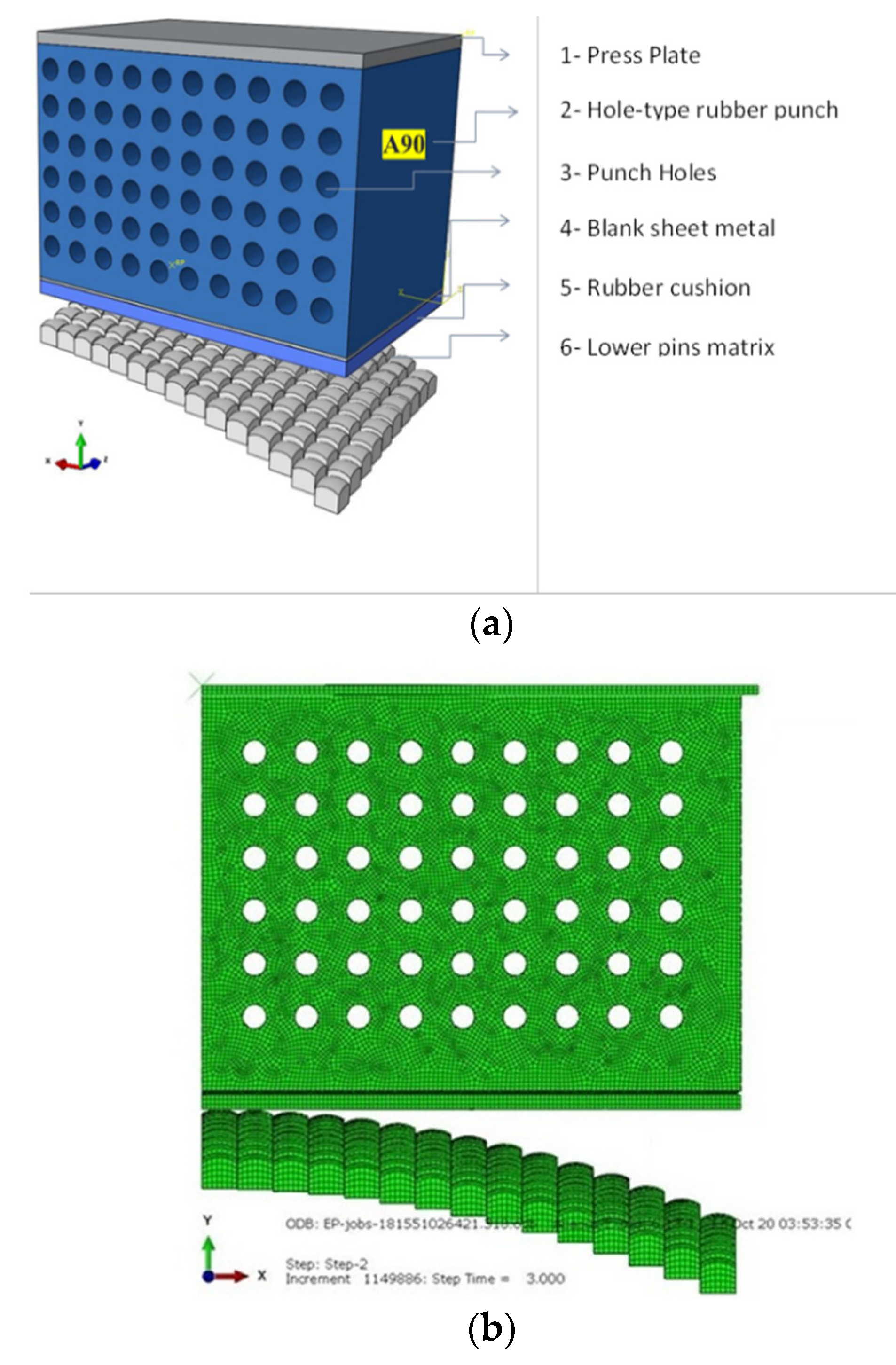
2.2. Finite Element Modelling

A Finite element model (FEM) was developed using ABAQUS CAE 2018 (Dassault Systèmes, Vélizy-Villacoublay, France) to investigate the effect of the application of a hole-type rubber punch in the multipoint forming, and it is shown in Figure 2. Due to the geometrical symmetry, only one-quarter of the setup was considered in the simulation to reduce the numerical calculation time. A general contact relation was employed to identify the interfacial contact between the multipoint forming parts. In addition, a friction coefficient of μ = 0.1, was considered between all bodies [30,31].
The hole-type rubber punch was modelled as a deformable body with 1 mm C3D8R quadratic elements. The number of elements was 87,280 for the hole-type rubber punch and 278,602 elements for the complete setup. The lower die matrix was modelled as a rigid body using R3D4 elements. The sheet metal was modelled using shell elements, S4R, as proposed by Wang et al. [32]. The forming force of multipoint forming process was applied as the displacement of the press plate node in the Y-direction. The die was constrained in all of the 6 degrees of freedom through appropriate boundary conditions, whereas XYZ rotation and XZ translational constraints were applied to the hole-type punch. Mesh sensitivity was carried out to optimise the appropriate element size at which an accurate solution can be achieved. An explicit solver from ABAQUS (Dassault Systèmes, Vélizy-Villacoublay, France) was used in the proposed FEM to prevent non-linear deformation convergence due to the complexity of the model. Finally, mass scaling of 10,000 was applied to reduce simulation time without reducing the model precision.

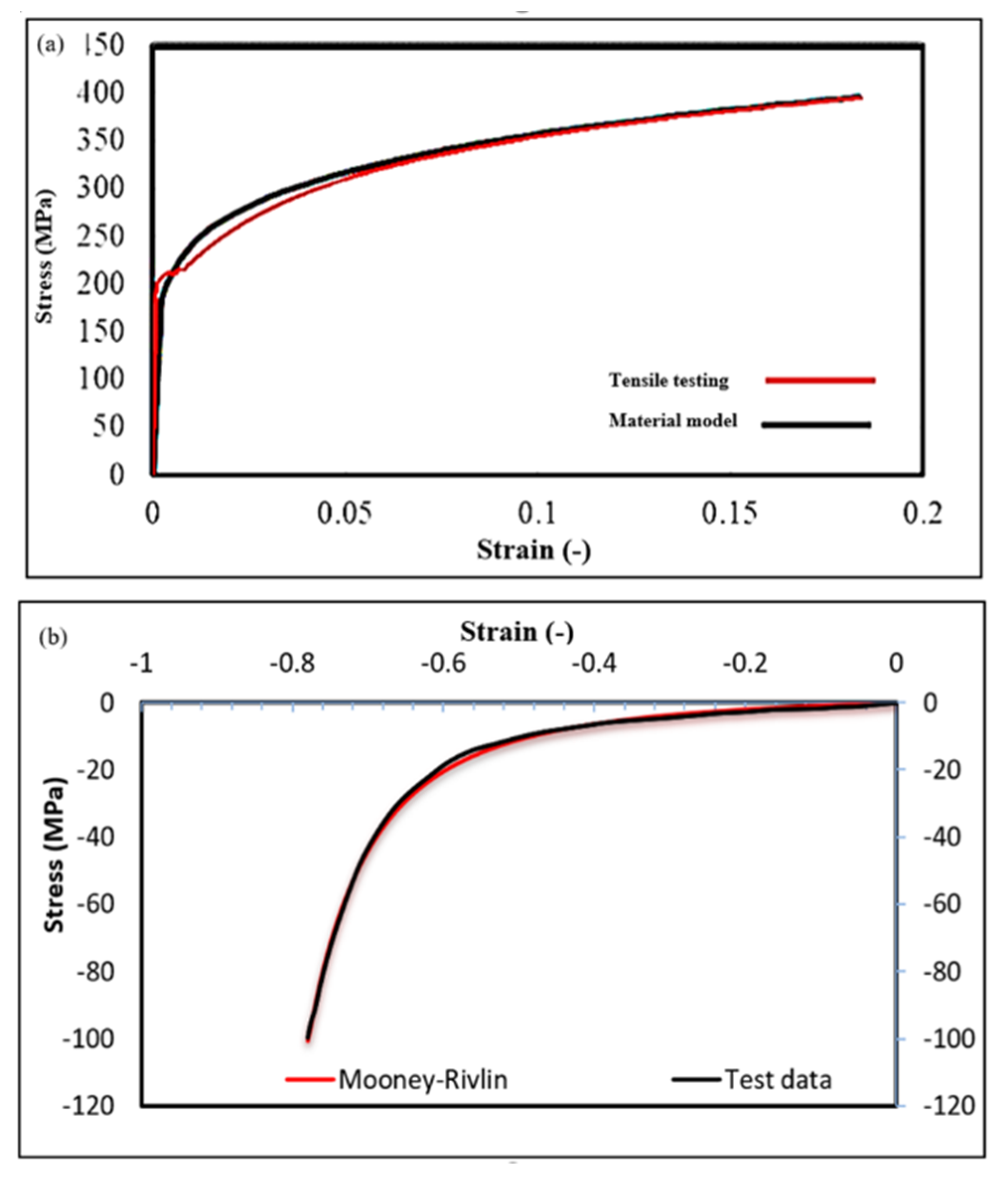
2.3. Materials Properties

The sheet material was DC05 steel with a 1 mm thickness. The tensile properties of the material were determined through a tensile test using standard mechanical testing equipment (Zwick, Birmingham, UK), according to the American Society for Testing and Materials standardASTM E8. It was assumed that the material properties are isotropic. Therefore, an elastic-plastic model was employed following a reduced Hollomon law, as shown in Equation (1).
σ = K ε n
where σ refers to developed stress, K is the strength coefficient, n is the strain exponent, and ε is the developed strain. The measured stress–strain properties were used to determine ( n and K ), see Figure 3a. The strength coefficient (K) was found to be 527.13 MPa and the strain-hardening exponent (n) was found to be 0.17 [12].
Polyurethane-A90 was used for the hole-type rubber and the elastic cushions. The material was also assumed to be isotropic, and its density was 1130 kg/m3. The compression properties of the rubber punch material were achieved using standard mechanical testing equipment (Zwick, Birmingham, UK). The material properties were compared to the Mooney–Rivlin model, and were found to be in good agreement with Abosaf et al. [12], see Figure 3b. As shown in the figure, the hyperelastic model (given in Equation (2)) effectively describes the hyperelastic characteristics of Polyurethane-A-90.
W = C o 1 ( I ¯ 1 3 ) + C 1 o ( I ¯ 2 3 ) + 1 D 1 ( J 1 ) 2
where W is the strain energy, C o 1 and C 1 o are the deviatoric response coefficients, I ¯ 1 and I ¯ 2 are the first and second invariants of the strain tensor, D 1 is the elastic volume ratio for isotropic thermal expansion, J is the volumetric response obtained from the experimental data. The Poisson’s ratio of the material was 0.475 [12].

2.4. Statistical Optimisation

The design of experiments (DoE) approach using a face-centred composite design was employed to investigate the influence of the hole-type rubber punch geometrical parameters such as compression ratio, hole size and hole shape on the quality of the formed part. The punch compression ratio is determined as t 0 t f t 0 × 100, where t f and t 0 are the rubber punch thickness at the final and beginning loading, respectively. The measured responses were the wrinkling, the shape deviation, and the thickness variation. Table 1 lists the studied parameters and levels. As shown in the table, the hole’s size and the compression have three numerical levels each. Whereas the hole’s geometry has two categorical levels (square or circular).
A second-order polynomial model was used to predict the response of the formed part, see Equation (3):
R e s p o n s e = A 0 + l = 1 n A l x m + l = 1 n A l l x l 2 + l < m A l m x l x m + e
where x is the input parameters, A is the polynomial coefficients, n is the number of independent factors, and e is an error Abosaf et al. [12].
Wrinkling was calculated as the root-mean-square-error (RSME) deviation between the formed part from the designed shape across the long edge of the deformed part [12]. The thickness variation was determined as the standard deviation of the formed part thickness along the primary axes. The shape deviation was defined as the maximum normal distance between the actual and the intended geometries.

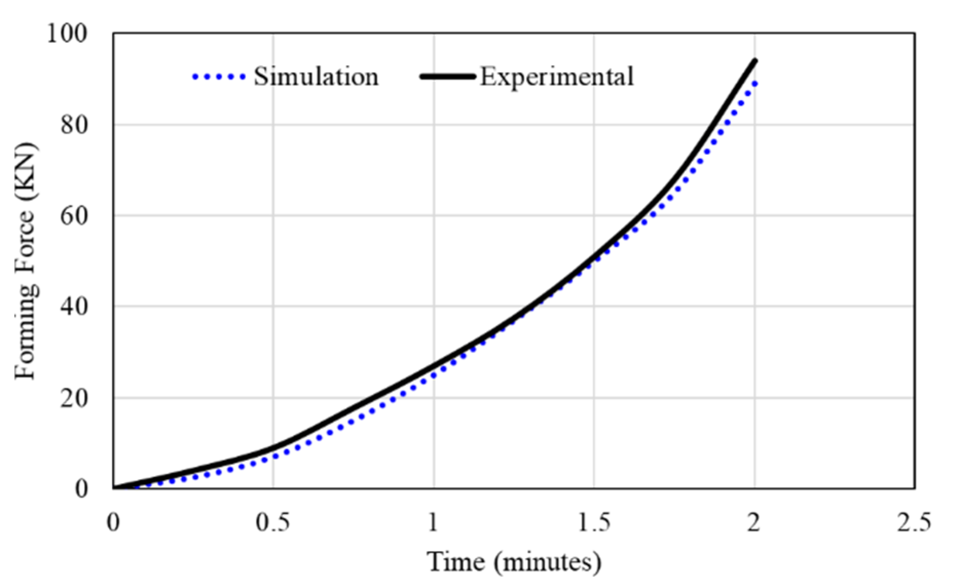
3. Results and Discussion

The simulation model was first validated by comparing the simulated and experimental results of the forming force which was measured by the force cell fitted on the multipoint forming setup. Figure 4 shows the forming force profile curves for two doubly curved manufactured parts of 400 mm radius of curvature produced by the hole-type rubber punch multipoint forming. As shown in the figure, the forming force starts to develop gradually and smoothly at an early stage until the process finishes. This demonstrates an improved performance as compared with conventional multipoint forming, where a rapid increase in the forming force is observed towards the end of deformation [12]. In general, the simulated results of the forming force fairly agree with the experimental one. Following this, the simulated results of the wrinkling, thickness variation, and shape deviation were obtained for the DoE optimisation (using input parameters: hole size, compression ratio, hole shape). Table 2 shows that the formed parts produced using a hole-type rubber punch with circular holes of 9 mm in diameter and a compression ratio of 70% showed the minimum wrinkling. On the other hand, minimum thickness variation can be obtained using a rubber punch with any hole shapes of a size of 9 mm and a compression ratio of 50%. Furthermore, minimum shape deviation was achieved using a rubber punch with circular holes of 3 mm in diameter and a compression ratio of 70%.
The simulation results listed in Table 2 were further investigated using analysis of variance (ANOVA) by the Design-Expert software 10 (Stateas, Birmingham, UK) to identify the significant input parameters statistically. The probability threshold of a 5% P-value was considered for all ANOVA analysis, which corresponds to 95% confidence level. As such, input parameters with probability p-values smaller than 5% are statistically significant. The smaller the p-value below 0.05, the more significant the parameter [12,13]. Table 3 lists the probability p-values of the hole size, compression ratio, hole shape, and their interactions. The results show that the hole size and compression ratio significantly affect the part wrinkling. On the other hand, the hole size, compression ratio, and hole shape were significant parameters on thickness variation. Furthermore, the compression ratio was the only factor affecting the shape deviation. It is worth noting that no parameter interactions have significant effects on wrinkling, thickness variation, or shape deviation.
Typically, wrinkling increases when in-plane tensile stresses are insufficient, creating out-of-plane wave-like deformation. These are because of developed local plastic deformation when the pressure increases until the maximum plastic deformation is achieved [33]. Therefore, and in order to eliminate wrinkles, the contact pressure has to be more than the induced compressive instability [34]. Figure 5 shows the influence of the hole size and the compression ratio on wrinkling. The figure shows that a significant reduction in wrinkling can be achieved by increasing the compression ratio from 50% to 70%. This is mainly due to the increased uniformity of the generated stresses as the compression ratio increases. On the other hand, wrinkling decreased with increasing the hole size from 3 mm to 9 mm. A possible explanation is that larger holes in the punch allow rubber to better flow towards the voids and prevents rubber material build-up between the pins and the rubber punch. This leads to less formation of waves deformation [33,34,35].
Figure 6 shows the effect of the hole size and punch compression ratio on the thickness variation for both circular and rectangular hole punches. The thickness variation decreases by increasing the hole size and decreasing the compression ratio. The minimum thickness variation was obtained when using a 9 mm hole size and 55% compression ratio for circular hole punches and at 9 mm hole size and 50% compression ratio for the rectangular hole punch. The large hole size allows the rubber punch to flow more while applying the load to the sheet. This prevents rubber punch material build-up against the pins and allows the rubber punch to compensate for any non-uniform deformation by the lower pins. This leads to more uniform deformation of the sheet material and reduces thickness variation [11,12]. On the other side, a low compression ratio leads to small plastic deformation, which leads to a more uniform distribution of compressive stresses under the pins. This leads to more thickness uniformity and reduces the thickness variation [11,12].
Figure 7 shows the influence of the compression ratio on the shape deviation. The figure shows that the shape deviation increases as the compression ratio increases. This is consistent and agrees with similar studies [12,34]. Increasing the compression ratio increases the local deformation, resulting in less uniform pressure distribution and an increase in sheet thinning at which the sheet metal thickness decreased. A minimum error from the required shape is obtained when the compression ratio of the rubber punch is 70%.
In order to obtain parts with high-quality characteristics in terms of wrinkling, thickness variation, and shape deviation, the optimal values of the input parameters in terms of hole size, hole shape, and compression ratio should be identified. In order to achieve this, a polynomial model that correlates the output variables with the input process parameters has been developed, as shown in Equation (4).
Response = x 0 + x 1 . A + x 2 . B + x 3 . C + x 4 .   AB + x 5   . AC + x 6 .   BC + x 7   . A 2 + x 8   . B 2 + x 9   . C 2
Table 4 shows the polynomial coefficients x 0   t o   x 9 for each of the three responses. To create a doubly curved part with R = 400 mm, the optimal conditions of the rubber punch parameters were obtained. In this work, the main objective function is set to minimise the wrinkling, thickness variation, and shape deviation. The process parameters that meet the objective function are found to be 75% punch compression ratio with a circular hole size of 9 mm.
Experimental work was carried out to fabricate a doubly curved steel panel of R = 400 mm using the optimised hole-type rubber punch parameters and was compared to the published results from solid rubber punch.
Figure 8 shows plots of the scanned formed part with optimised process parameters along the O-X and OB paths of the deformed part. As shown in the figure, there is a good agreement between the simulation and the experimental work.
Table 5 compares the modelled, the experimental, and the work reported by Elghawail et al. [29]. As shown, the modelled results are slightly lower than measured outputs. The prediction error is found to be less than 2%, which can be considered acceptable given the complex deformation of hole-type rubber punch. On the other hand, wrinkling of the formed part was reduced to 0.1082 mm when using the optimised hole-type rubber punch compared to 0.5340 mm obtained when using solid rubber punch (see Figure 9). This demonstrates an improvement of about 80%.

4. Conclusions

In this study, finite element analysis, design of experiments and experimental validation were used to investigate the optimisation of a novel hole-type rubber punch of a MIPF aiming to replace the top pin matrix and to reduce the cost and time by approximately 50%. The wrinkling of the doubly curved steel panel was significantly reduced, though the new configuration did not include the use of a blank holder. The design of experiments showed that the hole size was a significant parameter in its effects on the wrinkling, thickness variation, and shape deviation. On the other hand, the hole shape was found significant on the thickness variation and shape deviation. Furthermore, the compression ratio was found significant on the thickness variation. The main outcome is that a hole-type rubber punch MIPF can be employed to minimise the associated defects of the deformed part, with optimal parameters being achieved compared to samples fabricated using solid rubber punch. However, further experimental investigations are required to look at different rubber materials and more complex sheet metal geometries.

Author Contributions

Conceptualization, H.H., K.E.; Formal analysis, K.E., H.M.E. and K.E.; Funding acquisition, M.A.E.-S., H.M.E., A.K.A. and N.A.A.; Investigation, H.H., M.A.E.-S. and A.T.; Methodology, A.T., H.H. and K.E.; Project administration, H.M.E., A.K.A., N.A.A. and M.A.; Resources, M.A. and N.A.A.; Software, N.A.A., M.A.E.-S. and H.M.E.; Supervision, K.E.; Validation, A.T. and M.A.E.-S., K.E.; Writing—review & editing, H.H., M.A.E.-S., H.M.E., A.K.A., N.A.A. and M.A. All authors have read and agreed to the published version of the manuscript.

Funding

This research received no external funding.

Data Availability Statement

Not applicated.

Acknowledgments

The authors extend their appreciation to the Deanship of Scientific Research at Imam Mohammad Ibn Saud Islamic University for funding this work through Research Group No. RG-21-12-02.

Conflicts of Interest

The authors declare no conflict of interest.

References

  1. Atul, S.T.; Babu, M.C.L. A review on effect of thinning, wrinkling and spring-back on deep drawing process. Proc. Inst. Mech. Eng. Part B J. Eng. Manuf. 2019, 233, 1011–1036. [Google Scholar] [CrossRef]
  2. Wifi, A.S.; Abdelmaguid, T.F.; El-Ghandour, A.I. A review of the optimization techniques applied to the Deep Drawing process. In Proceedings of the 37th International Conference on Computers and Industrial Engineering 2007, Alexandria, Egypt, 20–23 October 2007; Computers and Industrial Engineering. pp. 97–107. [Google Scholar]
  3. Hagan, E.; Jeswiet, J. A review of conventional and modern single-point sheet metal forming methods. Proc. Inst. Mech. Eng. Part B J. Eng. Manuf. 2003, 217, 213–225. [Google Scholar] [CrossRef]
  4. Wankhede, P.; Suresh, K. A review on the evaluation of formability in sheet metal forming. Adv. Mater. Processing Technol. 2020, 6, 402–429. [Google Scholar] [CrossRef]
  5. Essa, K. Finite Element Prediction of Deformation Mechanics in Incremental Forming Processes; The University of Birmingham: Birmingham, UK, 2011; p. 217. [Google Scholar]
  6. Petunin, A.A.; Stylios, C. Optimization models of tool path problem for CNC sheet metal cutting machines. IFAC Pap. Online 2016, 49, 23–28. [Google Scholar] [CrossRef]
  7. Schuh, G.; Bergweiler, G.; Fiedler, F.; Bickendorf, P.; Colag, C. A Review on Flexible Forming of Sheet Metal Parts. In Proceedings of the 2019 IEEE International Conference on Industrial Engineering and Engineering Management, IEEM 2019, Macao, China, 15–18 December 2019; IEEE Computer Society: Washington, DC, USA, 2019; pp. 1221–1225. [Google Scholar]
  8. Yadav, A.; Jayswal, S.C. Modelling of flexible manufacturing system: A review. Int. J. Prod. Res. 2018, 56, 2464–2487. [Google Scholar] [CrossRef]
  9. Zhu, H.; Ou, H.; Popov, A. Incremental sheet forming of thermoplastics: A review. Int. J. Adv. Manuf. Technol. 2020, 111, 565–587. [Google Scholar] [CrossRef]
  10. Soltani-Tehrani, A.; Lee, S.; Sereshk, M.R.V.; Shamsaei, N. Effects of unit cell size on the mechanical performance of additive manufactured lattice structures. In Proceedings of the 30th Annual International Solid Freeform Fabrication Symposium—An Additive Manufacturing Conference, SFF 2019, Austin, TX, USA, 12–14 August 2019; pp. 2254–2262. [Google Scholar]
  11. Tolipov, A.; Elghawail, A.; Abosaf, M.; Pham, D.; Hassanin, H.; Essa, K. Multipoint forming using mesh-type elastic cushion: Modelling and experimentation. Int. J. Adv. Manuf. Technol. 2019, 103, 2079–2090. [Google Scholar] [CrossRef] [Green Version]
  12. Abosaf, M.; Essa, K.; Alghawail, A.; Tolipov, A.; Su, S.; Pham, D. Optimisation of multi-point forming process parameters. Int. J. Adv. Manuf. Technol. 2017, 92, 1849–1859. [Google Scholar] [CrossRef] [Green Version]
  13. Tolipov, A.A.; Elghawail, A.; Shushing, S.; Pham, D.; Essa, K. Experimental research and numerical optimisation of multi-point sheet metal forming implementation using a solid elastic cushion system. J. Phys. Conf. Ser. 2017, 896, 012120. [Google Scholar] [CrossRef] [Green Version]
  14. Liu, C.; Li, M.; Yue, T. Springback prediction method for double-curved workpiece considering plate anisotropy in multi-point forming. J. Mech. Sci. Technol. 2021, 35, 2623–2636. [Google Scholar] [CrossRef]
  15. Yang, J.; Fu, W.; Li, M.; Yang, Y. Optimization of multi-point forming for aluminum alloy profile. In Materials Science Forum; Trans Tech Publications Ltd.: Freienbach, Switzerland, 2021; pp. 13–17. [Google Scholar]
  16. Liu, C.; Li, M.; Qu, E. Springback prediction and compensation method for anisotropy sheet in multi-point forming. Proc. Inst. Mech. Eng. Part C J. Mech. Eng. Sci. 2022, 236, 511–524. [Google Scholar] [CrossRef]
  17. Liang, J.; Han, C.; Li, Y.; Liang, C.; Jin, W. The influence of multi-point roller-dies on the shape deviation differences of profile in flexible stretch-bending forming. Proc. Inst. Mech. Eng. Part B J. Eng. Manuf. 2021, 09544054211041067. [Google Scholar] [CrossRef]
  18. Moheen, M.; Abdel-Wahab, A.; Hassanin, H.; Essa, K. Reconfigurable Multipoint Forming Using Waffle-Type Elastic Cushion and Variable Loading Profile. Materials 2020, 13, 4506. [Google Scholar] [CrossRef] [PubMed]
  19. Lee, J.W.; Kwon, H.C.; Rhee, M.H.; Im, Y.T. Determination of forming limit of a structural aluminum tube in rubber pad bending. J. Mater. Processing Technol. 2003, 140, 487–493. [Google Scholar] [CrossRef]
  20. Quadrini, F.; Santo, L.; Squeo, E. Flexible forming of thin aluminum alloy sheets. Int. J. Mod. Manuf. Technol. 2010, 2, 79–84. [Google Scholar]
  21. Chen, L.; Chen, H.; Guo, W.; Chen, G.; Wang, Q. Experimental and simulation studies of springback in rubber forming using aluminium sheet straight flanging process. Mater. Des. 2014, 54, 354–360. [Google Scholar] [CrossRef]
  22. Păunoiu, V.; Maier, C.; Teodor, V.; Găvan, E. Numerical analysis of multipoint forming process. Int. J. Mod. Manuf. Technol. 2011, 3, 85–90. [Google Scholar]
  23. Quan, G.-Z.; Ku, T.-W.; Kang, B.-S. Improvement of formability for multi-point bending process of AZ31B sheet material using elastic cushion. Int. J. Precis. Eng. Manuf. 2011, 12, 1023–1030. [Google Scholar] [CrossRef]
  24. Zareh-Desari, B.; Habibi-Yengejeh, S.; Davoodi, B.; Vafaeesefat, A. Experimental Investigation and Finite Element Simulation of Effect of Mechanical Properties of Elastic Cushion on Spring-Back in Multi-Point Forming Process. Aerosp. Mech. J. 2014, 11, 63–73. [Google Scholar]
  25. Younis, K.M.; Aljarjary, A.I.; Shukur, J.J. Numerical and experimental investigation of parameters affect the forming load during rubber pad sheet metal forming. In Proceedings of the 2nd International Conference on Sustainable Engineering Techniques (ICSET 2019), Baghdad, Iraq, 6–7 March 2019; IOP Publishing: Bristol, UK, 2019; pp. 032012–032049. [Google Scholar]
  26. Spoelstra, P.; Djakow, E.; Homberg, W. Rubber pad forming—Efficient approach for the manufacturing of complex structured sheet metal blanks for food industry. In Proceedings of the 20th International ESAFORM Conference on Material Forming (ESAFORM 2017), Dublin, Ireland, 26–28 April 2017; AIP—American Institute of Physics: College Park, MD, USA, 2017; pp. 080004–080006. [Google Scholar]
  27. Hongyu, W.; Zhen, W.; Fei, T.; Pengchao, Z.; Juncai, S.; Shijun, J. Numerical simulation and experiment research on forming of two-step channel based on rubber pad pressing. Int. J. Adv. Manuf. Technol. 2019, 101, 2175–2189. [Google Scholar] [CrossRef]
  28. Fei, T.; Hongyu, W.; Juncai, S.; Xiangwei, K.; Jie, S.; Shunhu, Z. Thickness analysis of complex two-step micro-groove on plate during rubber pad forming process. Proc. Inst. Mech. Eng. Part C J. Mech. Eng. Sci. 2021, 235, 122–135. [Google Scholar]
  29. Elghawail, A.; Essa, K.; Abosaf, M.; Tolipov, A.; Su, S.; Pham, D. Low-cost metal-forming process using an elastic punch and a reconfigurable multi-pin die. Int. J. Mater. Form. 2019, 12, 391–401. [Google Scholar] [CrossRef] [Green Version]
  30. Cai, Z.-Y.; Wang, S.-H.; Li, M.-Z. Numerical investigation of multi-point forming process for sheet metal: Wrinkling, dimpling and springback. Int. J. Adv. Manuf. Technol. 2008, 37, 927–936. [Google Scholar] [CrossRef]
  31. Abebe, M.; Lee, K.; Kang, B.-S. Surrogate-based multi-point forming process optimization for dimpling and wrinkling reduction. Int. J. Adv. Manuf. Technol. 2016, 85, 391–403. [Google Scholar] [CrossRef]
  32. Shaohui, W.; Zhongyi, C.; Mingzhe, L.; Yingwu, L. Numerical simulation on the local stress and local deformation in multi-point stretch forming process. Int. J. Adv. Manuf. Technol. 2012, 60, 901–911. [Google Scholar]
  33. Zhou, B.-J.; Xu, Y.-C. The effect of upper sheet on wrinkling and thickness distribution of formed sheet part using double-layer sheet hydroforming. Int. J. Adv. Manuf. Technol. 2018, 99, 1175–1182. [Google Scholar] [CrossRef]
  34. Elghawail, A.; Essa, K.; Abosaf, M.; Tolipov, A.; Su, S.; Pham, D. Prediction of springback in multi-point forming. Cogent Eng. 2017, 4, 1400507. [Google Scholar] [CrossRef]
  35. Peng, L.; Hu, P.; Lai, X.; Ni, J. Fabrication of metallic bipolar plates for proton exchange membrane fuel cell by flexible forming process-numerical simulations and experiments. J. Fuel Cell Sci. Technol. 2010, 7, 031009. [Google Scholar] [CrossRef]
Figure 1. The experimental setup of the hole-type rubber multipoint forming. 1—Force Cell; 2—Displacement sensor; 3—Hole-type rubber punch; 4—Sheet blank; 5—Rubber cushion; 6—Lower pin matrix.
Metals 12 00491 g001
Figure 2. (a) The model setup; (b) the model Mesh.
Metals 12 00491 g002
Figure 3. (a) The material flow model and the tensile testing curve of DC05 steel sheet; (b) The compression diagram compared to Mooney–Rivlin model for Polyurethane-A90 punch.
Metals 12 00491 g003
Figure 4. The measured and the simulated results of the forming force.
Metals 12 00491 g004
Figure 5. Effects of the hole size (mm) and the compression ratio (%) on wrinkling (mm).
Metals 12 00491 g005
Figure 6. Effects of hole size (mm) and the compression ratio (%) on the thickness variation (mm), (a) circular holes, (b) rectangular holes.
Metals 12 00491 g006
Figure 7. Effect of the compression ratio (%) on the mean of the shape deviation (mm).
Metals 12 00491 g007
Figure 8. Comparisons between the simulation, experimental, and target shape at (a) O-X side, (b) at OB path.
Metals 12 00491 g008
Figure 9. Parts produced used: (a) solid adapted from [29], and (b) Hole-type rubber punch MPIF configurations. (a) Solid rubber punch MPIF [24]. (b) Hole-type rubber punch MPIF.
Metals 12 00491 g009aMetals 12 00491 g009b
Table 1. Hole-type punch process parameters.
ParameterUnitLevel
−101
Hole size (A) mm3 × 36 × 69 × 9
Compression ratio % (B)%506070
Hole geometry (C) Square Circular
Table 2. Design of experiment results of the wrinkling, thickness variation, and shape peak deviation.
RunFactor 1 Hole Size (mm)Factor 2 Compression
Ratio (%)
Factor 3 Hole ShapeResponse 1 Wrinkling [mm] Response 2 Thickness Variation [mm]Response 3 Shape Deviation [mm]
1650Circular2.06000.005041.323
2970Circular0.30660.003180.399
3950Square1.80100.003131.801
4660Circular2.00400.006130.54
5350Circular3.12800.005451.078
6960Circular1.01100.005450.97
7360Square2.87900.006620.67
8370Circular1.69400.007000.3
9350Square2.27700.005451.58
10660Square2.00700.005450.79
11950Circular1.60100.003131.011
12670Circular1.77200.006540.44
13960Square1.04400.003450.47
14650Square3.07000.004811.067
15370Square2.69940.009980.4
16360Circular2.07100.003881.33
17670Square1.17100.007880.79
18970Square1.18200.009210.32
Table 3. p-value of the investigated parameters and the two-factor interactions. Values in bold indicate significant parameters.
Process Parameter Response Factors
Wrinkling Thickness VariationShape Deviation
Hole size (A)mm0.0010.0100.757
Compression Ratio (B)%0.0120.0470.002
Hole shape (C) 0.2460.0060.746
Significant Interactions-AB = 0.46
AC = 0.06
BC = 0.32
AB = 0.992
AC = 0.727
BC = 0.051
AB = 0.895
AC = 0.829
BC = 0.597
Table 4. Polynomial coefficients for the response variable equation.
Polynomial CoefficientResponse Variable
Wrinkling [mm] Thickness Variation [mm]Shape Deviation [mm]
x 0 14.336.488−261. 9
x 1 −0.0110.0290.179
x 2 −0.052−0.089−0.019
x 3 −0.255−0.1994.690
x 4 −0.00001−0.000040
x 5 0.00006−0.000170
x 6 0.000270.009100
x 7 0.00001−0.001070
x 8 0.000160.002520
x 9 0.001600.014100
Table 5. Results at optimal process variables of the hole-type rubber punch.
ParameterHole Size [mm]Compression Ratio %Hole-Type-Wrinkling (mm)Thickness Variation (mm) Shape Deviation (mm)
Optimal conditions975CircularFEM0.10660.003180.399
Exp. 0.10820.003220.393
Elghawail et al. [24].Solid PunchExp.0.534
Publisher’s Note: MDPI stays neutral with regard to jurisdictional claims in published maps and institutional affiliations.

