1. Introduction
The new potential and opportunities of Additive Manufacturing (AM) technologies are currently under investigation in different production fields [
1,
2]. According to these studies, one fundamental challenge concerns the identification of the most suitable AM technique on the basis of the product’s requirements and characteristics [
3], as different AM technologies are associated with different benefits and issues. The positive balance of benefits and challenges is particularly convenient in binder jetting (BJ) process technology. BJ can theoretically process any type of metal and ceramic powder feedstock, guarantee a high production rate, and the printing operation does not require a high-energy source or controlled atmosphere [
4]. Nevertheless, the as-built product encounters high dimensional changes on sintering, which can detrimentally affect the product’s quality [
4,
5]. For these reasons, the success of BJ technology depends on the future development of design methods accounting for dimensional changes and on the related process set-up.
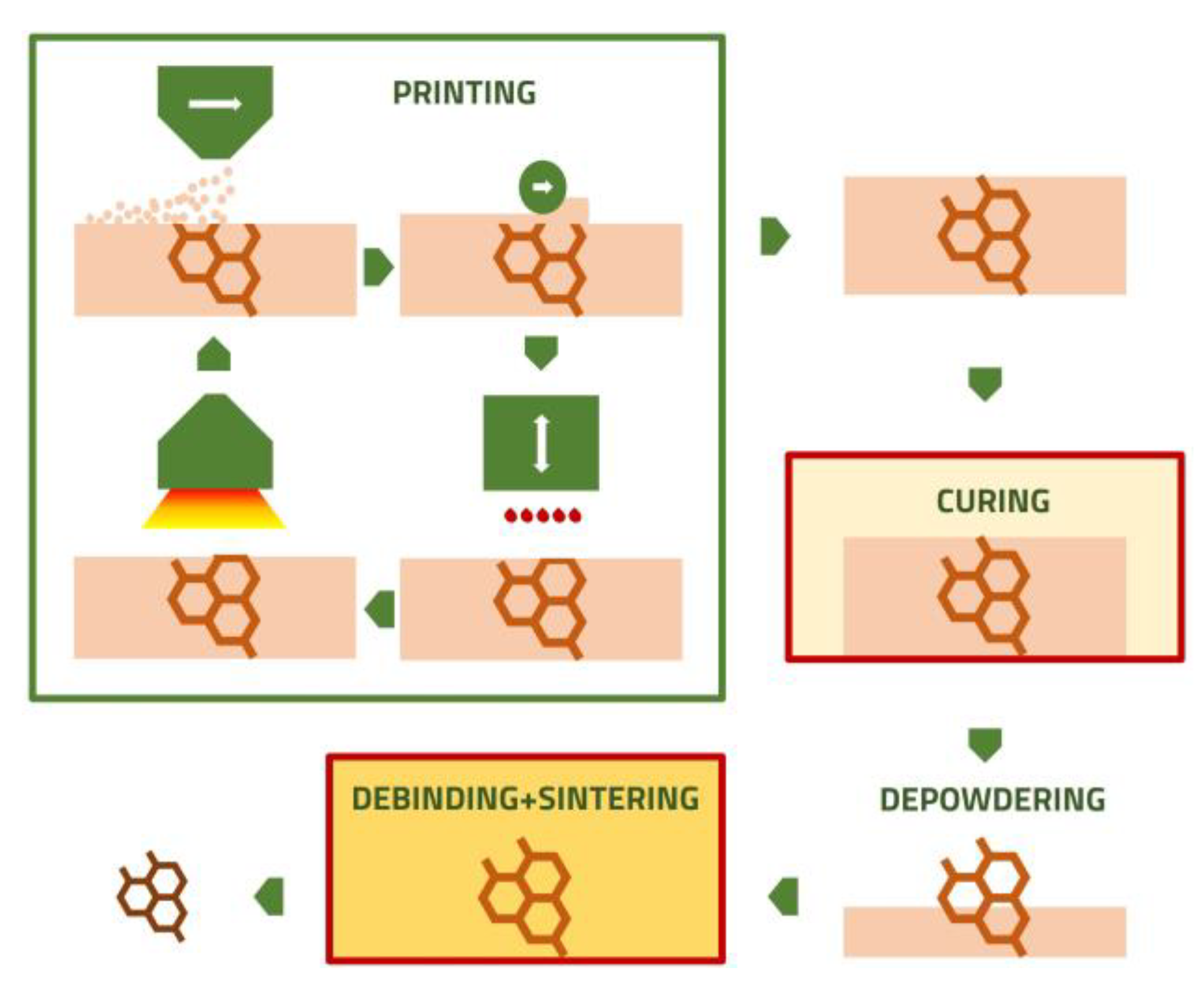
BJ is an AM process, based on a sliced CAD file, which serves as the basis to build-up the product layer-by-layer. A powder layer is spread on a table in a printing chamber, and, successively, a binder agent is injected and dried, corresponding to the section area of the CAD file. After repeating powder spreading and binder injection, the green product is obtained. A thermal treatment, inducing the crosslinking of the binder to enhance the mechanical resistance of the green product, is then performed (curing), followed by de-binding and sintering to consolidate the structure, as shown in
Figure 1.
The shape of products obtained using the BJ process is theoretically unlimited; nevertheless, the layer-by-layer process leads to novel constraints related to the building orientation. In fact, as effectively reviewed by Taufik and Jain, building orientation influences several characteristics: the product quality, the surface finishing, the need for support, the building time and cost [
6]. These new challenges stimulated the development of new design methodologies, generally called design for additive manufacturing (DfAM) [
7,
8]. Different DfAM methodologies were specifically developed for layer-by-layer manufacturing. Arni e Gupta modelled the effect of a staircase on flatness form error [
9]. Paul and Anand designed an algorithm to minimize the flatness and cylindricity form error and the need for support [
10].
The layer-by-layer building process is only one possible source of geometrical inaccuracy, with respect to the nominal geometry, as reported in different works. Crane demonstrated that an improper control of part thickness and drying conditions leads to an excessive saturation level, which produces bleeding defects on sample surfaces [
11]. Other works reported defects induced by layer shifting, which are attributed to an excessive saturation level, or to an improper powder spreading set-up [
12,
13]. Miyanaji et al. experimentally verified that binder droplet shifts from a nominal impacting zone on increasing printing speeds and, consequently, the partial accuracy along binder injection direction decreases [
14]. Similarly, Parab et al. observed, using high-speed X-ray imaging, a drift of droplets from the impact zone, and the possible formation of satellites [
15]. Excessive saturation level and printing speed can reasonably induce defects along the binder injection direction; in addition, layer shifting perpendicular to the printing direction is also reported in other works [
16,
17,
18].
To date, the literature has mainly focused on the analysis of an as-built product, disregarding the influence of the sintering process on the geometrical precision and accuracy of sinter-based AM parts. Few studies have analyzed the accuracy of BJ-sintered products. Zhao et al. experimentally studied, using the Taguchi method, the influence of process parameters on the dimensional accuracy and surface roughness of AISI 316L and 420 stainless-steel powder metal parts [
19,
20]. In a previous work, Zago et al. validated a model to predict the shape variation in cylindrical holes. The experimental results demonstrate the role of both the anisotropic dimensional sintering change and the green accuracy on the final quality of sintered products produced by BJ [
21].
This study aims to investigate the factors that affect the flatness form error in the green and sintered states of BJ products, on the basis of previous experience with sinter-based parts [
22,
23,
24,
25,
26]. Five sample geometries were fabricated, presenting a plane at different inclination angles, to study the influence of both the layer-by-layer manufacturing and the sintering process on the final product. A careful analysis of the surface morphology was performed. On the basis of these experimental results, some hypotheses have been proposed to explain the most relevant sources of geometrical error.
2. Materials and Methods
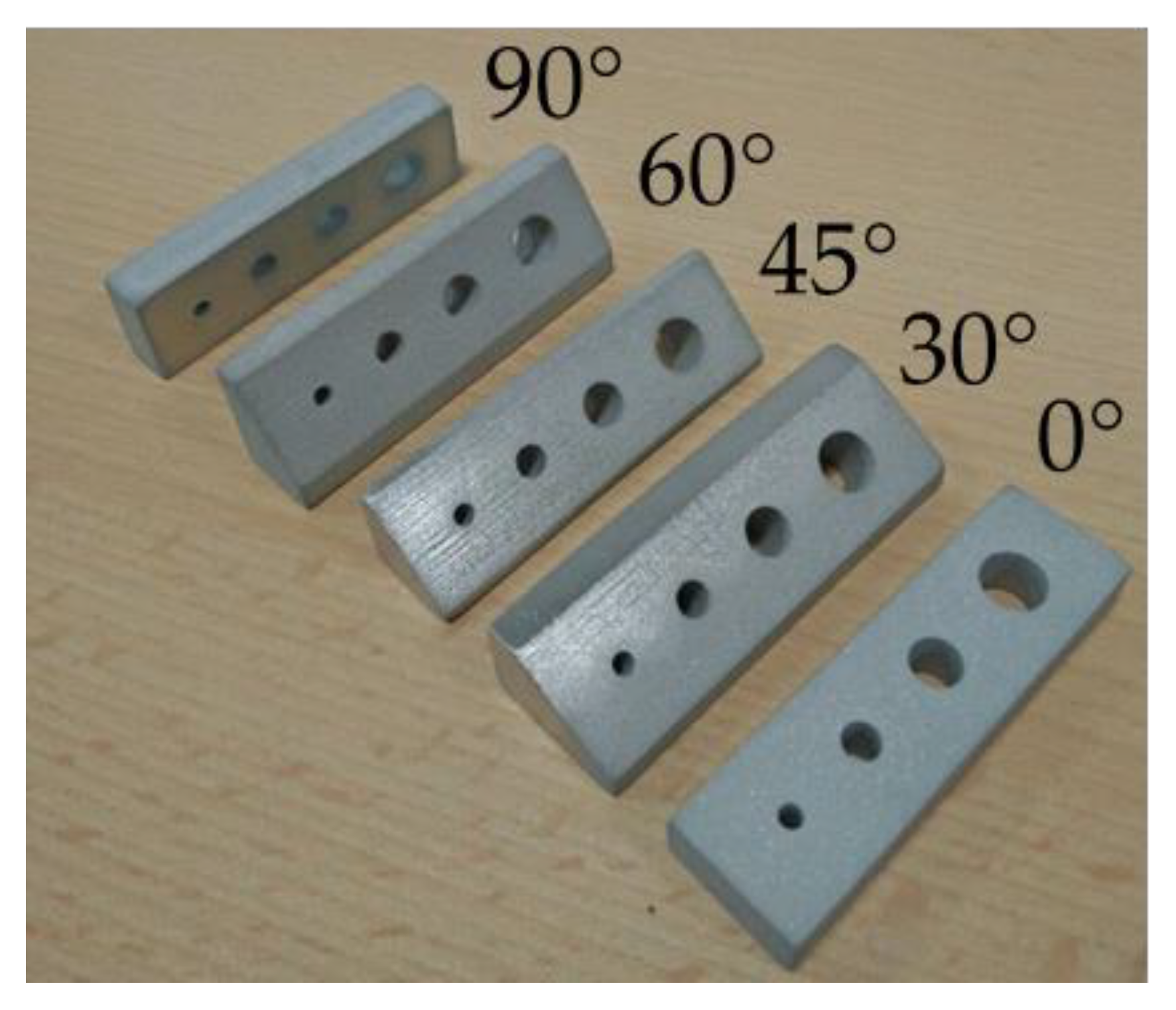
Five sample geometries were designed to study the dimensional and geometrical accuracy of planes produced at different inclination angles with respect to the fabrication direction. As shown in
Figure 2, each geometry has a plane 70 mm × 20 mm wide, whose normal vector determines an angle of 0°, 30°, 45°, 60° and 90° with respect to the fabrication direction. This surface is named plane D.
Each sample presents four through holes, whose diameter’s nominal dimensions are 3 mm, 5 mm, 7 mm, and 9 mm, respectively. Other dimensions differ per sample to provide a constant hole depth, as explained in Reference [
21].
Gas-atomized AISI 316L powder has been used, with particle size distributions of D90 25 μm, D50 10 μm, D10 4 μm, as declared by the Sandvik AM (Sweden) supplier. Samples were produced by an Innovent Plus 3D printer machine (ExOne, North Huntingdon, PA, USA); process parameters are reported in
Table 1. The process set-up was derived using the calibration procedure reported in Reference [
27]. Interruptions to the printing process were required to realize minor maintenance operations and avoid major deviations in the printed components from the CAD files.
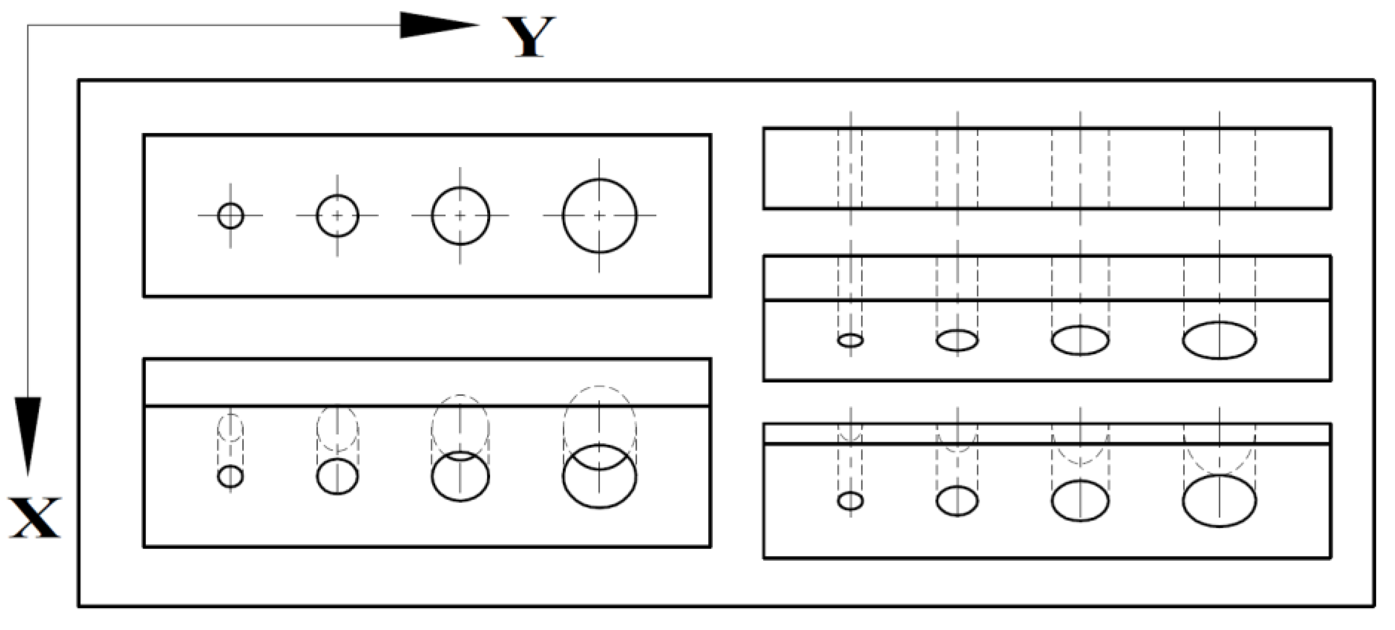
In a single batch, one replicate was fabricated for each geometry, with the major dimension of each sample aligned with the printhead movement direction, as shown in
Figure 3. Three batches were produced under the same conditions to fabricate three replicates for each geometry.
The arrangement in
Figure 3 was designed according to the building chamber size to highlight the causes of the geometrical inaccuracy of nominally flat surfaces. In addition, considering the position of samples in the printing area, it is theoretically possible to discover the printing errors associated with part location, as was performed by Vitolo et al. [
28].
After the printing process, samples were cured for 3 h at 180 °C according to ExOne recommendation. Successively, extra powders were carefully removed, avoiding any possible damage to green parts. The samples were measured by a Global DEA 07-07-07 coordinate measuring machine (CMM, Hexagon, Stockholm, Sweden), with a maximum permissible error of 1.5 + L/333 μm, according to ISO 10360-2 [
29]. The acquisition system consists of a Renishaw SP600M touch-probe, which mounted a sphere tip with a diameter of 1 mm.
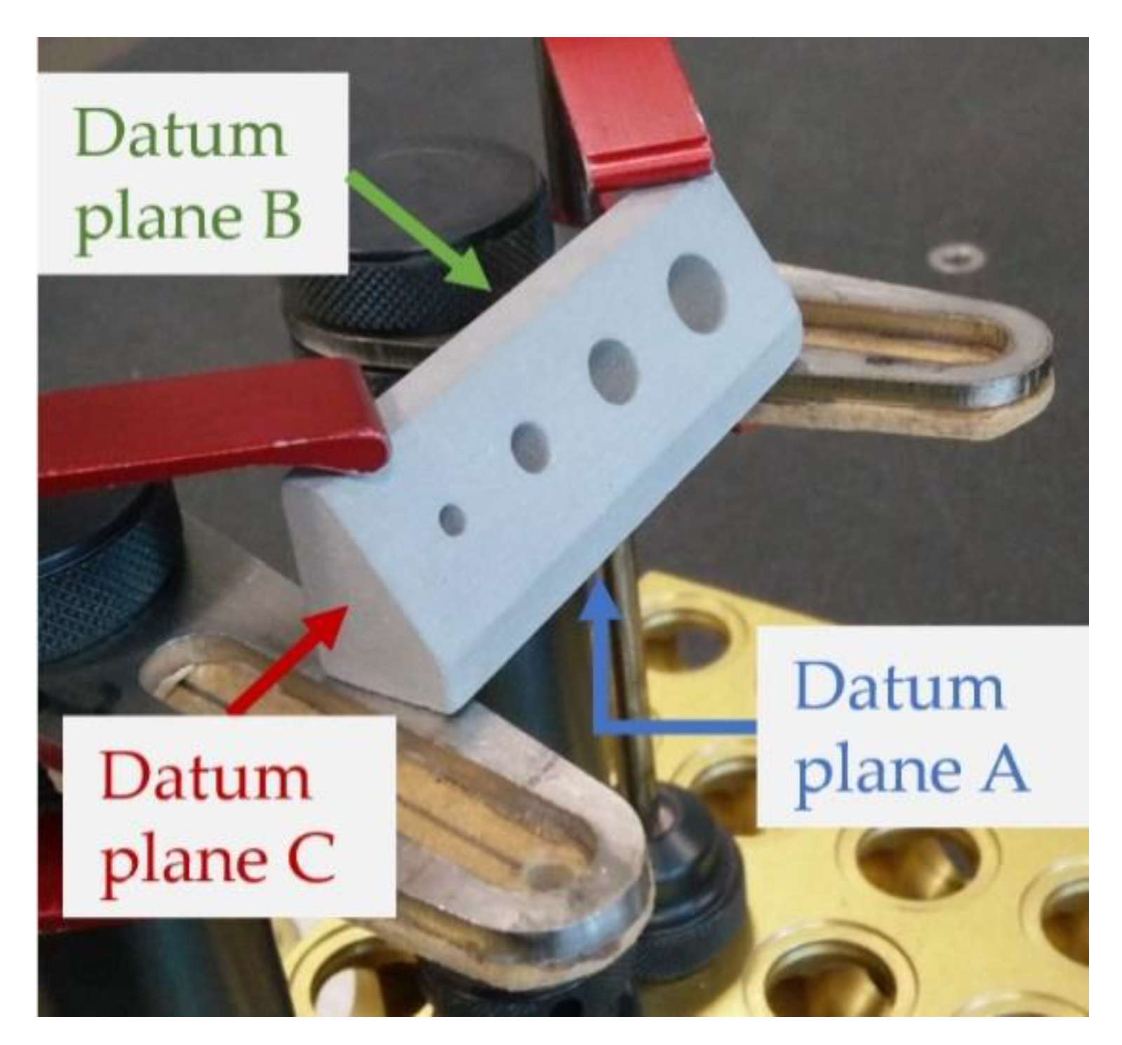
Samples clamping in the CMM working plane are shown in
Figure 4.
A specific measurement procedure was programmed for each sample in the Hexagon Pc-Dmis 2019R2 suite (Hexagon, Stockholm, Sweden). The routine initially performed a 3-2-1 alignment of sample Datum Reference Frame with respect to the machine reference frame. The primary (A), secondary (B) and tertiary (C) datum planes are indicated in
Figure 4. A detailed description of the measurement procedure is given in Reference [
21]. After alignment, from 50 to 150 points were acquired on each surface and used to reconstruct the planes by a gaussian best-fit least-squares method. The flatness form error was also calculated, for use as an indicator of the quality of the 3D printing process.
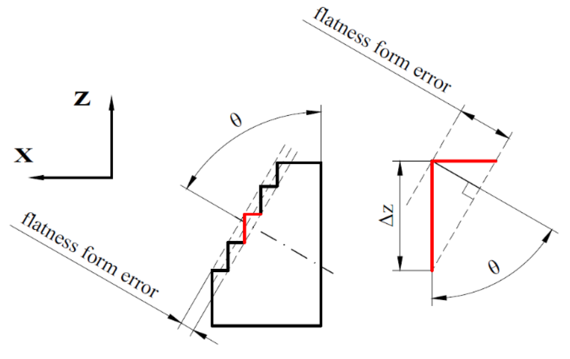
As is well known, the layer-by-layer process produces the staircase error schematized in
Figure 5.
The flatness error due to the staircase effect can be predicted by Equation (1), according to the Arni e Gupta formulation [
9]
where Δz is the layer thickness and θ
g is the angle between the fabrication direction and the plane vector in the green state.
After measurement, green samples were de-binded for 4 h at 470 °C in Argon atmosphere and sintered in a vacuum furnace for 3 h at 1360 °C. On the sintering cycle, the heating rate was set at 5 °C/min and the furnace pressure was 10−1 mbar. Sintered samples were measured using the procedure previously developed for green parts, with proper corrections due to shrinkage.
After sintering, flatness error is influenced by the dimensional change and can be expressed by Equation (2)
where ε
z is the dimensional change along the Z direction (fabrication direction), derived by the normalized difference in dimensions parallel to the Z axis, and expressed by Equation (3)
where l
s represents the dimension at sintered state, and l
g is the dimension at green state. θ
s is the novel angle resulting from anisotropic dimensional changes in sintering, which is expressed by Equation (4), as detailed in [
21].
The anisotropic dimensional change in sintering, with higher dimensional change along fabrication direction than in the building plane, is confirmed by several studies on binder jetting process [
30,
31,
32].
3. Results
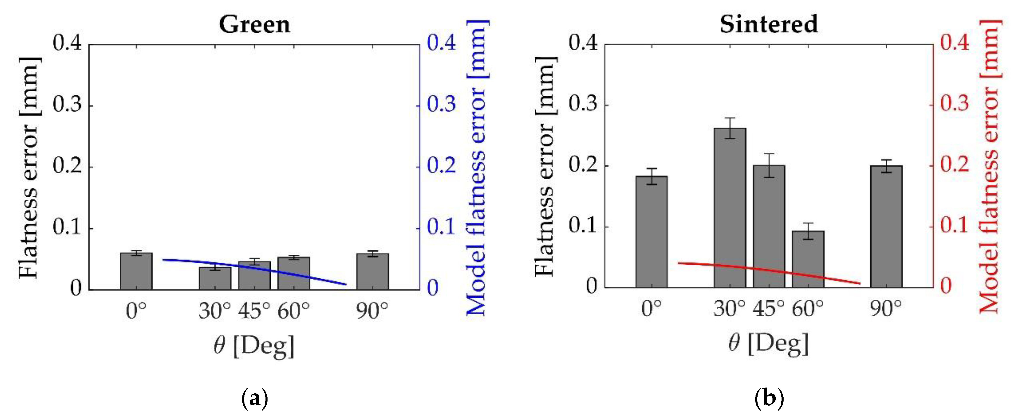
The flatness form error of plane D is shown in
Figure 6 for the samples in the green (6a) and sintered state (6b), respectively. The estimated flatness error induced by the staircase error was calculated by Equations (1) and (2), and is reported with the empirical data. Concerning the printing parameters, the layer thickness (Δz) is assumed to be equal to 50 μm, the nominal building angle (θ
g) is derived from CAD geometry and the dimensional changes in X and Z directions (ε
x and ε
z) are assumed to be equal to −15.5% and −17.8%, respectively, corresponding to the average dimensional change in the linear dimensions, as reported in Reference [
21].
From the experimental results, the flatness error very slightly increases at the green state upon increasing the inclination angle from 30° to 90°. However, the trend is not systematic, since samples 0° show the same flatness error as samples 90°. Sintered samples show a pronounced decrease in flatness error upon increasing the inclination angle from 30° to 60°, while the flatness of samples 0° and 90° are out of the trend and, again, very similar. A significant worsening of flatness is also generally observed after sintering. No definite influence of the staircase effect is shown by the results above at either the green or sintered state. In fact, at the green state, the empirical data trend contrasts with the model prevision, although the absolute values are quite similar. At the sintered state, the model significantly underestimates the flatness form error. Consequently, other mechanisms should originate the surface irregularity, in addition to the staircase induced by the layer-by-layer manufacturing process. To highlight other causes of surface error, a more in-depth analysis of the data is reported. The below analysis concerns the surface irregularity of the replicate presenting the higher flatness form error at green and sintered states for each geometry.
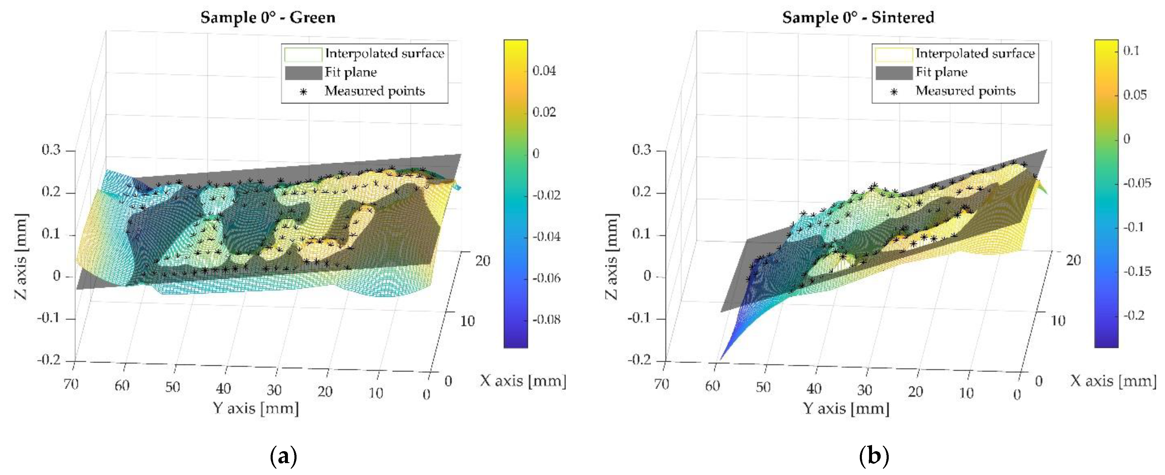
Figure 7 shows the reconstructed surface of plane D for sample 0° at the green (
Figure 7a) and sintered (
Figure 7b) states, respectively; the asterisk symbols represent the points measured by CMM, the semi-transparent grey surface corresponds to the plane derived by the gaussian best-fit least-squares method of such points. The colored surface represents a surface obtained by the natural neighbor interpolation method of the measured points. The color bar shows the coordinates of the interpolated surface along the Z direction. It should be noted that the interval identified by the color bar does not correspond to the measured flatness form error. The colored surface was obtained by extrapolating the measured points up to the nominal area of plane D, not strictly corresponding to the overall area obtained by the measured points. The clamping system did not allow for the probe to access the plane edges; therefore, the colored surface in such regions was unconstrained by the measured points and the shape curvature determined a fake overestimation of flatness form error. This is not considered here; the only scope of reconstruction provides a visual representation of the irregularities in the different samples by looking at the measured area.
In the green state, the surface displays an irregular morphology. Different sources of the surface defectiveness of BJ green products are reported in the literature. Li et al. observed surface ridges on the powder bed surface in the case of compaction thickness (defined as the excess of powder spread regarding nominal layer thickness) that were higher than the layer thickness [
33]. Nevertheless, in this study, compaction thickness was lower than the layer thickness, and the visual inspection of powder bed surface during the printing operation did not reveal such surface defectiveness, so it was excluded as a source of the irregular surface. As suggested by Chen and Zhao, the irregular surface might depend on the binder–powder interaction, and specifically on the printing saturation level [
19]. The saturation level is defined as the volume fraction between the binder volume and the volume of voids, considering the theoretical density of the powder bed [
4]. A low saturation level means that the binder does not bond powders with sufficient strength; therefore, some particles might detach from the nominal surface, creating cavities. On the other hand, a high saturation level could attach extra powders, creating protrusions when compared to the nominal geometry. A slight variation in binder saturation can be expected, which is likely related to the droplets injected by the print-head or to the particle size distribution. Tang et al. experimentally verified the different wettability of the binder on two different particle size distributions. The particle size determining a higher powder bed density produces a slight increase in the contact angle and a dramatic increase in infiltration time [
34]. Therefore, powders in a dense arrangement (high powder bed density) determine a high saturation level, while low packed powders (low powder bed density), are related to a lower saturation level. Consequently, a non-homogeneous powder density distribution might result in an irregular surface, enhanced by the variation in saturation level.
The above hypothesis can also be confirmed by analysis of the sintered surface. The dimensional change in sintering is affected by the homogeneity in density distribution, which is, in turn, related to regular powder packing, and this is expected to amplify the surface irregularities that were highlighted at the green state. The role of holes should be further investigated; there is no evidence of a recurring scheme close to the circular section at both the green and the sintered states.
Moreover, moving along the Y axis, the Z coordinates of measured points tend to decrease, more evidently on sintered samples. Although this does not affect flatness error, the effect has to be considered, determining an increase in the parallelism error with respect to plane A (from 0.103 mm in the green state up to 0.312 mm in the sintered state).
The slope of the plane could be related to a gradient in powder bed density along the Y axis. Some evidence of a slight inhomogeneity in powder bed density has been demonstrated by Lores et al., using the same printing machine and a similar printing set-up with 17-4 PH stainless-steel powder [
35]. According to the ANOVA study of Barthel and Wieland, samples with a higher green density achieve a higher sintered density and higher dimensional change [
36].
The increased slope in the sintered state might also be related to an inhomogeneous heating rate of the sample during the sintering process. The presence of holes is associated with a non-uniform sample section, which might have determined a faster heating rate of material close to bigger hole. As a consequence, a more pronounced densification and higher shrinkage is expected close to bigger holes, which could have provoked the increased slope. Both hypotheses are reasonable and could have occurred simultaneously. Further work is in progress to highlight the prevailing mechanism.
In conclusion, the flatness form error of sample 0° in the green state could be ascribed to slight differences in saturation level at the printing stage, which determine an irregular morphology, which is further enhanced upon sintering by the dimensional change. Future work will investigate the role of any inhomogeneity of green density in the powder bed and the thermal transient analysis of the sample upon sintering.
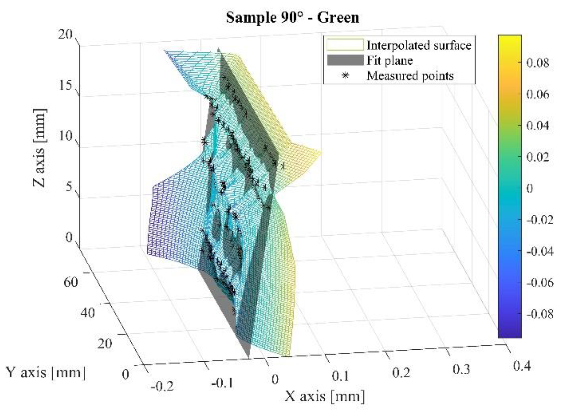
Figure 8 reports the reconstructed surface of plane D of sample 90° at the green state. The figure shows the measured points, the best-fit plane and the interpolated surface, as in
Figure 7.
As shown in
Figure 8, the points measured at the same Z coordinates are systematically located left or right to the best-fit plane. The flatness form error could be related to the so-called bleeding defect, which corresponds to a binder migration outside the nominal area due to an oversaturation of binder level. Another hypothesis ascribed the flatness-form error to the fabrication of layers that were not in the same nominal positions. This error could possibly be caused by some limits in the electro-mechanical actuator of the printhead control system.
A slight drift in the measured points towards the X direction can also be observed in
Figure 8, which could be directly related to a layer shift. To prove this, the position of the points measured on datum plane B was analyzed as follows.
Figure 9 provides the axonometric view of sample 30°, showing the datum reference system XYZ and the pattern of points acquired on the datum plane B (parallel to plane Y-Z). These points were projected in
Figure 10 on a plane parallel to X-Z plane, as indicated by the arrow “X-Z view” in
Figure 9. In addition to the points of sample 30°,
Figure 10 reports the points acquired on the datum plane B in the other geometries, according to the datum reference system of each sample.
Figure 10 confirms the layer-shifting upon increasing the Z coordinate in all samples. Some works have already reported the layer shifting defects induced by excessive saturation levels, but their relationship with binder injection direction is not specified [
12,
13]. Cao et al. demonstrated a clear correlation between the layer shifting along the powder-spreading direction and the flatness form error [
16]. In the cited study, experimental data show a significant increase in flatness form error upon decreasing compaction thickness, likely due to the powder failure mechanism. In another paper, Maximenko et al., using discrete-element modeling, simulated the influence of powder-spreading on the accuracy of previously deposited parts [
17]. Although the experimental data do not exactly fit the model prevision, there is evidence that powder deposition could cause a layer drift in the same direction as powder spreading, as clearly shown in
Figure 10.
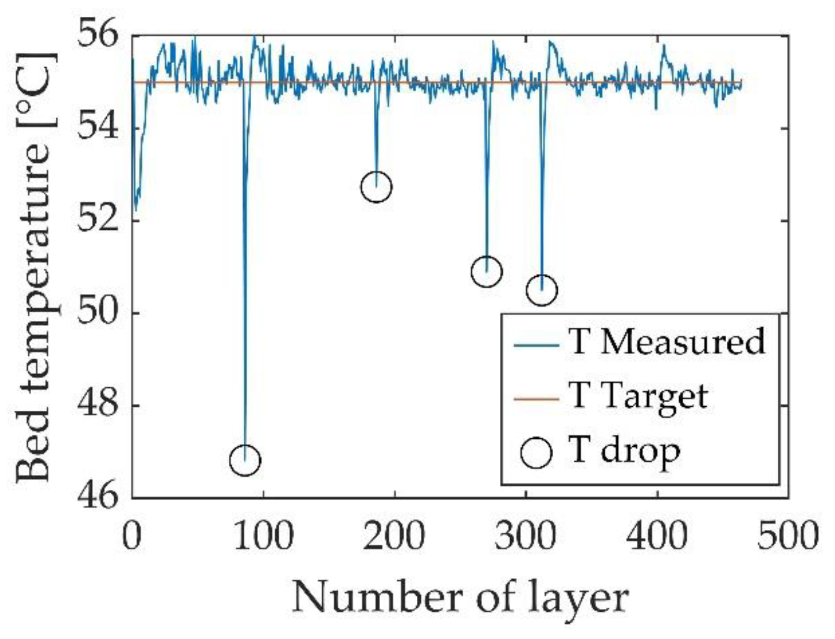
Figure 10 also reveals that some measured points are positioned outside the general trend identified by the layer shifting. The irregular position of some layers is more evident at lower Z coordinates and tends to reduce on increasing sample height. This result is related to the four temperature drops that occurred in the building chamber during the fabrication of one sample batch, as shown in
Figure 11, represented in
Figure 10 by the dashed lines. Similar trends were observed in the other batches.
The temperature drops occurred whenever the printing process was paused and the machine was opened to perform maintenance operations (e.g., cleaning the spreading roller, cleaning the printhead, checking the cleanliness of the hopper sieve) aiming to avoid more relevant issues. As is well known, temperature drops cause a dramatic reduction in the drying speed and, consequently, layers could be pushed away by the roller movement, as described in the Innovent Plus 3D printing system user manual. Miyanaji et al. clearly show the part distortion caused by insufficient drying [
18]. The layer shifting reported by Miyanaji produces a layer drift that is opposite to the powder-spreading direction, as shown in
Figure 10: points close to the dashed lines (corresponding to the temperature drops highlighted in
Figure 11) tend to shift in direction opposite to spreading direction, and the effect is more evident close to the deeper temperature drop.
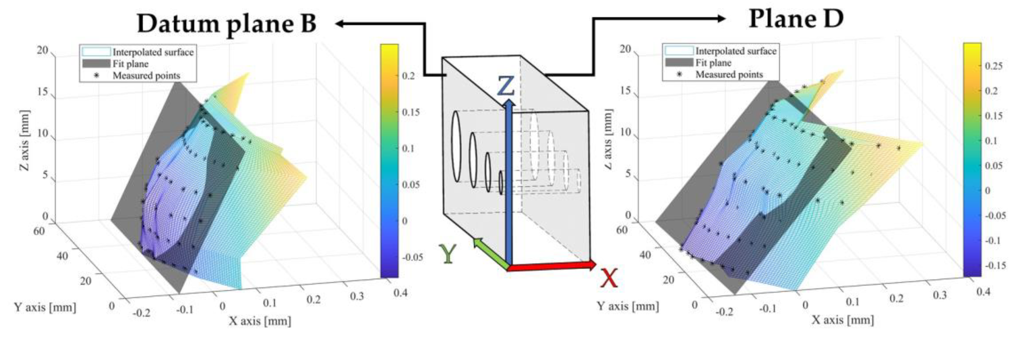
Figure 12 clearly shows that flatness form error can be directly ascribed to the shape deformation of the sintered sample. The concave shape of plane D is also confirmed in the opposite plane, datum plane B, which shows the same deformation, as displayed in
Figure 13 referred to sample 90°.
The dimensional change in sintering determines the shape distortion, which is likely due to the differences in the powder bed density at the green state, as explained above. The inhomogeneous heating rate of plane B and plane D, and the consequent thermal deformation, should also be considered. Differing from sample 0°, the presence of holes does not play a major role: plane D heated up faster, likely due to its position in the furnace and, consequently, densified earlier than plane B, causing distortion.
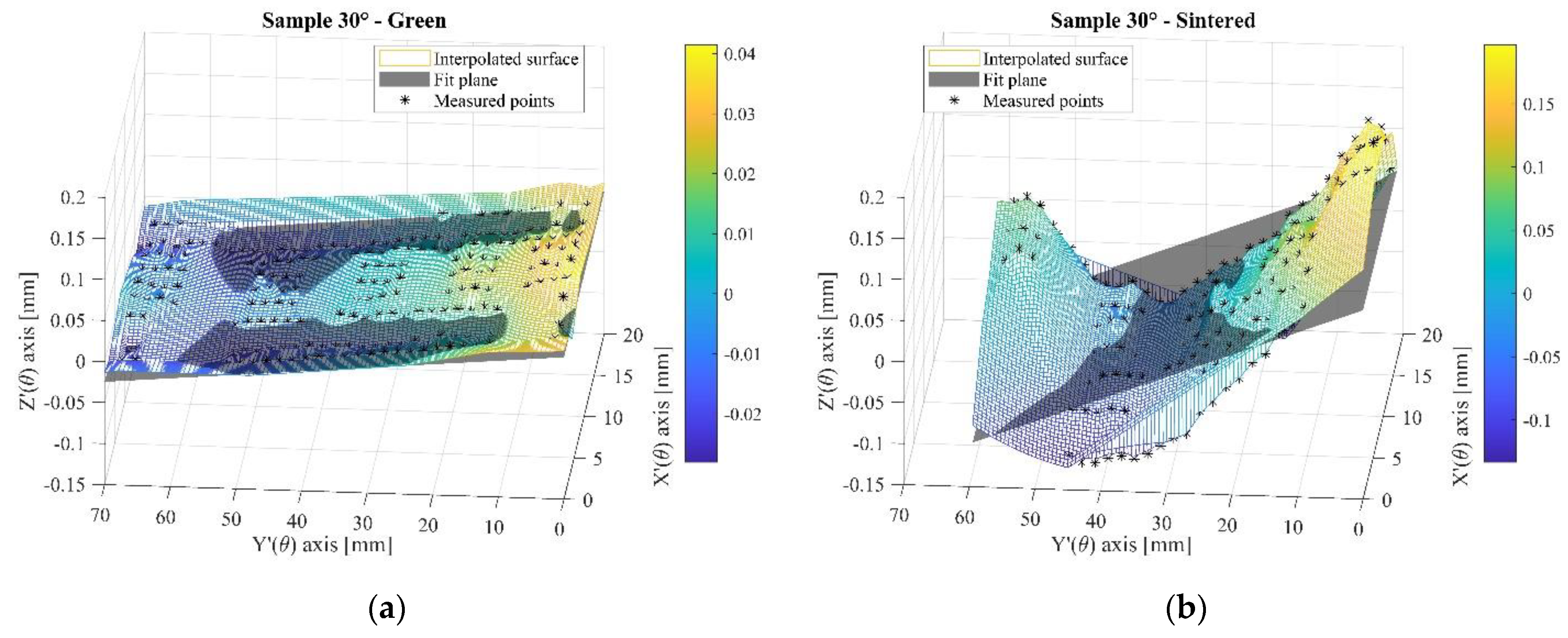
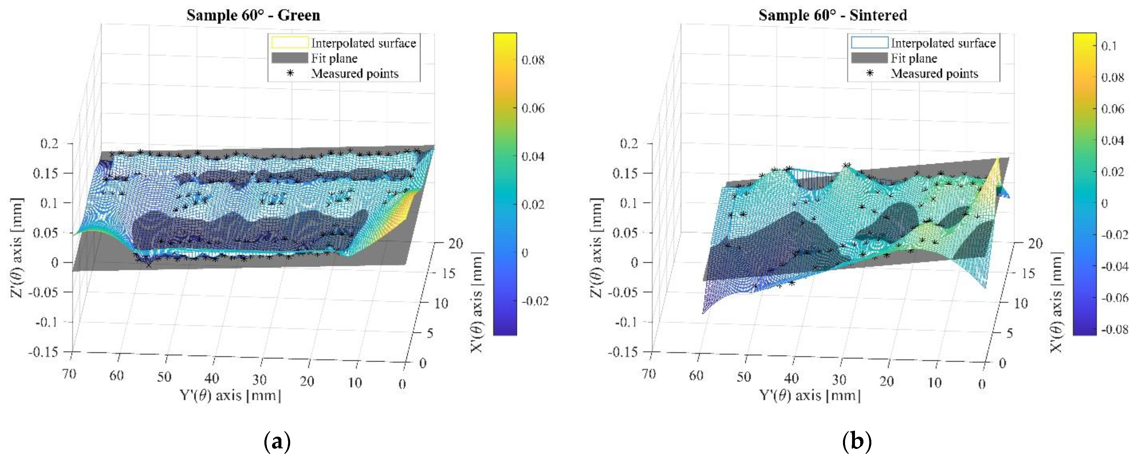
Figure 14,
Figure 15 and
Figure 16 show plane D of samples 30°, 45° and 60° at the green and sintered states. Aiming to highlight the flatness form errors, a new X′(θ)Y′(θ)Z′(θ) reference system was adopted, corresponding to the different orientations, so that X′(θ)-Y′(θ) was the reference plane parallel to plane D, and Z′(θ) represents the direction perpendicular to the plane. The color bar shows the coordinates of the interpolated surface along the Z′(θ) direction.
Figure 14a,
Figure 15a and
Figure 16a confirm the slightly irregular surface in green parts, likely to be attributed to the differences in saturation level. Again, the surface morphology is not significantly affected by the presence of holes. As highlighted above, referring to
Figure 10, layer shift is supposed to play the major role in determining the flatness form error at the green state in the investigated sampling.
The analysis of sintered surfaces displayed different causes of flatness form error. In samples 30° and 45°, flatness form error is clearly related to the shape deformation, as observed in sample 90°. In agreement with the previous assumption, the higher thermal irradiation in plane D determined the thermal deformation and an inhomogeneous shrinkage. No shape deformation was observed in sample 60°, and the flatness form error is clearly associated with the amplification of the irregular morphology observed in the green state, as discussed in sintered sample 0°.
Upon increasing the inclination angle, the mechanisms observed for sample 0° prevail.
The transient thermal state of the sample during the sintering heating stage will be investigated in more depth in future work to clarify the origin of distortion.


