Review

Magnetron Sputtering High-Entropy Alloy Coatings: A Mini-Review

by
Sai Krishna Padamata
1,2,
Andrey Yasinskiy
1,3,*,
Valentin Yanov
1,4 and
Gudrun Saevarsdottir
2,5
1
Laboratory of Physics and Chemistry of Metallurgical Processes and Materials, Siberian Federal University, 660025 Krasnoyarsk, Russia
2
Department of Engineering, Reykjavik University, 102 Reykjavik, Iceland
3
IME Process Metallurgy and Metal Recycling, RWTH Aachen University, 52056 Aachen, Germany
4
Institute of Materials Science and Technology, TU Wien, 1060 Vienna, Austria
5
Department of Materials Science and Engineering, NTNU, NO-7491 Trondheim, Norway
*
Author to whom correspondence should be addressed.
Metals 2022, 12(2), 319; https://doi.org/10.3390/met12020319
Submission received: 4 January 2022 / Revised: 7 February 2022 / Accepted: 7 February 2022 / Published: 11 February 2022
(This article belongs to the Special Issue Design of High-Entropy Alloys)

Abstract

:
Surface coatings can enhance the substrate material’s properties and increase its lifetime. HEA-based materials have been extensively investigated as coating materials due to their superior hardness, excellent oxidation and corrosion resistance, effective diffusion barrier properties and wear resistance. Magnetron sputtering has been regarded as one of the most efficient methods for the deposition of HEA-based thin films. Metallic- and nitride-based HEA coatings can be easily deposited by introducing N2 gas along with the Ar in the reaction chamber. The parameters such as target composition, bias voltage, sputtering power and notably, gas flow ratio, influence the thin film’s morphology and mechanical properties.

1. Introduction

High-entropy alloys (HEAs) have been a topic of interest in the field of metallurgy since their discovery in 2004 by Yeh et al. [1]. HEAs contain at least five elements with an atomic range of between 5% and 35%, having simple solid-solution phases (i.e., FCC, BCC, HCP or even a mixture of these phases) despite their complex chemical composition [2]. For instance, in Al-Co-Cr-Fe-Ni alloy, the volume fraction of FCC and BCC phases depends on the Al wt.% in the alloy [3]. An increase in the Al composition in the alloy leads to the transformation of FCC to BCC phases and vice versa [4]. HEAs exhibit high strength and hardness, superior thermal stability, excellent wear and corrosion resistance and good fracture toughness [5,6,7,8,9]. These attractive properties increase the potential of HEAs in engineering applications. HEAs can also be defined based on the entropy value [10]. The entropy of an alloy increases with the molecular randomness in the crystal lattice [11]. The molecular randomness is associated with the number of constituent elements in the alloy. The ideal configurational entropy of mixing is as follows:
Δ S m i x = R Σ z i l n z i
where R is the universal gas constant and zi is the molar fraction of the ith element. The mixing entropy of equiatomic HEAs is as follows:
Δ S m i x = R l n z
Here, z is the constituent element in HEAs; thus, increasing the number of elements in the alloy increases the entropy and forms a solid solution (according to Equation (2)). An alloy with a mixing entropy ΔSmix ≥ 1.5R and atomic size difference δ < 6.6 is considered as a HEA [1,12]. Here, δ can be defined from the below equation:
δ = i = 1 n z i ( 1 r i r   ¯ ) 2
where n is the number of elements, zi is the molar fraction of the ith element, ri is the atomic radius of the ith element, and r   ¯ is the mean atomic radius.
Surface coating is an efficient technique to enhance the mechanical and functional properties of the material. HEAs and HEA-based materials can be used as coating materials, which can drastically improve the surface characteristics of the substrate material. The HEAs used as thin films or thick coatings on the substrate can increase the endurance at optimal deposition parameters [13]. For instance, aluminum and its alloys, widely used in the aerospace, military and automotive industries, have low density, high thermal conductivity and easy formability. However, the alloys lack high hardness and good wear and corrosion resistance. By depositing HEA coatings of Al, a significant improvement in the overall mechanical and chemical properties can be attained [14,15].
The HEA coatings can be fabricated using magnetron sputtering (MS), arc cladding, laser cladding, thermal spraying and electrodeposition [16]. Table 1 presents the main advantages and disadvantages of the mentioned coating techniques. In particular, MS is an interesting coating technique as both HEA metal-based and ceramic-based as well as multi-layered coatings can be deposited [13]. The constituent elements used in this coating technique are usually nitride- or carbide-forming elements. The coating through MS has low diffusivity, high corrosion resistance and high hardness, which can be used as diffusion barriers [17,18]. The deposition parameters can effectively tune the physical properties, microstructure and grain size of the HEA layer. In general, a thin film with desired stoichiometry can be easily fabricated using the MS process. The deposited thin films can be quenched at a rate of 109 K/s, limiting the concentration fluctuation in the coatings. The MS process has high deposition efficiency but is also time-consuming. This paper discusses the HEA coatings by MS, deposition parameters influencing the characteristics of the coating and related applications based on recently published work on the MS coating.

2. Magnetron Sputtering Coating

In the MS technique, an electric field is generated between two electrodes within a vacuum chamber. In general, inert argon gas is pumped into the chamber and is positively ionized due to the electric field colloids with the electric field’s negatively charged plate (cathode). The collision of Ar+ ions with the targeted material located on the cathode leads to the ejection of atoms/molecules (constituent elements of HEAs) from the target area towards the substrate [20,21]. The ionization and collision rates of Ar on the target material in the sputtering system influence the deposition rate and coating thickness. Introducing the magnets underneath the target can create a magnetic field, which traps the secondary electrons emitted by the target into the discharge and increases Ar’s ionization, increasing the collision rate between the Ar+ and the target material (see Figure 1). The HEA film’s stoichiometry can be easily controlled by varying the chemical composition of the target material and the operational parameters. HEA nitride, carbide and oxide coatings can be readily synthesized by introducing N2, C2H2 and O2 gases along with the Ar gas.
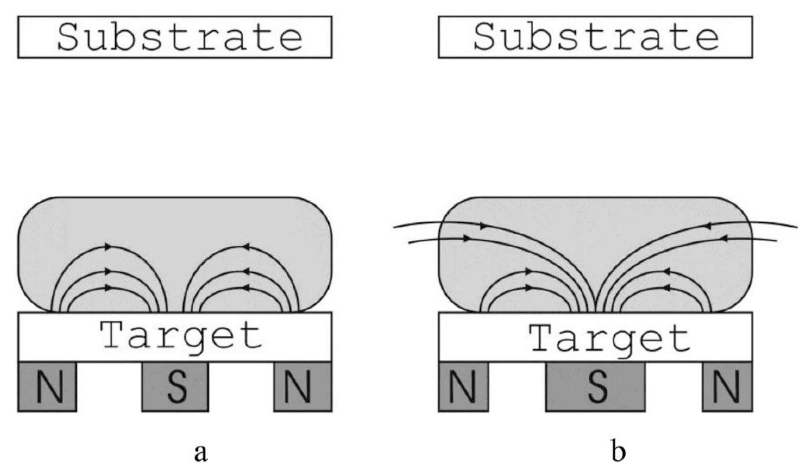
MS can be either balanced (conventional) or unbalanced based on the configuration of the magnetic field between the magnetic poles that form magnetrons. In balanced MS, the magnets are arranged so that the magnetic field lines coming out of the outer poles at the target surface close within the sputtering chamber at the inner poles at the target surface. In contrast, only a few magnetic field lines are closed between the inner and outer poles in an unbalanced MS magnetic system. The unclosed magnetic field lines are radially directed towards the walls of the sputtering chamber [22]. The magnetic fields in balanced and unbalanced MS are schematized in Figure 2.
The sputtering targets are usually prepared using the vacuum arc-melting method and remelted and solidified several times to ensure chemical homogeneity, then cut to the desired geometry and polished [23]. Schwarz et al. [23] deposited a CoCrFeNi coating using two different targets prepared via spark plasma sintering. One of the targets was prepared from a homogeneous HEA powder fabricated using gas atomization, while the second target was prepared from direct sintering of a pure element powder mixture. The authors reported that coatings with a similar chemical composition and structure were deposited from both targets. However, they pointed out that targets prepared from the powder mixture are more economical and easier to prepare [23]. Cemin et al. [24] fabricated AlSiTaTiZr thin films using 5-element mosaic assembly, circular (“pizza-shaped” geometry, Figure 3a), using the MS method. The sputter yield of Al is double compared to that of Si, Ta, Ti and Zr when considering argon impinging with energies < 1 KeV (as shown in Figure 3b). Therefore, the Al section was designed at half the size compared to the size of other elements. The stoichiometry of HEA thin films was Al10Si19Ta44Ti11Zr16, with a thickness of 2.2 µm and had an amorphous structure.
Cemin et al. [25] investigated the influence of substrate bias voltage on the deposition of NbTaTiVZr thin films. For grounded substrate, the crystal structure of NbTaTiVZr was a randomly oriented, polycrystalline BCC pure metal structure with low hardness. For low substrate bias voltage (−25 V), there was an increase in crystalline size and roughness of the top layer, which is associated with the low-energy argon ions accelerated towards the growing film, having the ability to enhance the adatom ability. For high substrate bias voltages (−75 V), argon ion bombardment accelerates and results in smoother films with higher lattice strains and higher hardness. The substrates are initially cleaned with acetone, pure alcohol and then de-ionized water. Before the deposition process, the target and substrate are cleaned by Ar bombardment for at least 2 min to remove any contaminants or oxides present on the target surface [26,27]. The substrate temperature during the deposition influences the grain size and lattice constant of the HEA-nitride coating. With an increase in the substrate temperature, the grain size increases due to thermal migration enhancement of surface adatoms under deposition. At the same time, the substrate temperature did not affect the HEA-nitride structure and remained FCC for substrate temperatures between 100 and 500 °C [27]. Khan et al. [26] studied the influence of sputtering power on the thickness and hardness of AlCoCrCuFeNi thin films deposited on the Si wafer by the radiofrequency MS method. The authors reported that when an increase of sputtering power occurred from 200 to 300 W, the hardness of the thin films significantly dropped from 13.0 ± 2.5 to 4.5 ± 0.3 GPa, while the film thickness increased from 80 ± 3 to 100 ± 7 nm.
Shaginyan et al. [28] prepared an equimolar AlFeCoNiCuCrV HEA coating by the magnetron sputtering method, where the coating has a nanocrystalline microstructure that presents a solid two-phase solution (BCC + FCC). An increase in the bias voltage (ranging from 0 to −200 V) increases the hardness of the HEA coating. The Al, Cu and Ni composition in the HEA coating decreases at high bias voltages with increasing ion bombardment intensities. This phenomenon could have occurred due to the preferential sputtering of Al, Cu and Ni elements on the coating surface, leading to a decrease in their composition on the HEA coating or scattering of Al, Cu and Ni atoms sputtered from the target during their movement towards the substrate caused by the Ar atoms’ collisions with these particular elements. A drastic decrease in Al, Cu and Ni composition in coatings can be avoided if the bias voltage is less than −160 V. It was also revealed that the ion bombardment intensities do not affect phase change, meaning the phase remained BCC + FCC for different ion energies. The maximum hardness of the HEA coating was 19.0 GPa at a bias voltage of −200 V.
Nitride-based HEA coatings can be readily prepared using magnetron sputtering. Nitride-based films can be prepared by introducing N2 gas along with Ar gas into the vacuum chamber. The stoichiometry of (HEA)xNy can be easily controlled by varying the nitrogen flow ratio, RN = N2/(Ar + N2). Cheng et al. [29] deposited (AlCrMoTaTiZr)N coatings at different RN using magnetron sputtering, using equimolar AlCrMoTaTiZr targets. The distance between the target and the substrate material was 75 mm, and the applied power of the target was 150 W. The substrate temperature was 400 °C, and coating thickness varied between 1.2 and 1.5 µm depending on the RN value. The coating deposited at RN = 0 has an amorphous structure. However, nitride-based coatings (at least 37% nitrogen) have NaCl-type FCC structures. (AlCrMoTaTiZr)N film exhibited the highest hardness of 40.2 GPa when coatings were deposited at RN = 40%. The HEA-nitride layer was wear-resistant with a wear rate of 2.8 × 10⁻⁶ mm3/N m. It is worth noting that target poisoning occurs at higher nitrogen, oxygen or acetylene flow rates or ratios, resulting in a decrease in the deposition rate of the coating [28,30]. Besides the target composition, parameters such as bias voltage and gas (N2, O2 or CH4) pressure influence the surface morphology and mechanical properties of HEA-based coatings deposited by magnetron sputtering. Table 2 includes the details about HEA-based thin films fabricated using the MS method.

3. Properties

3.1. Mechanical Behavior

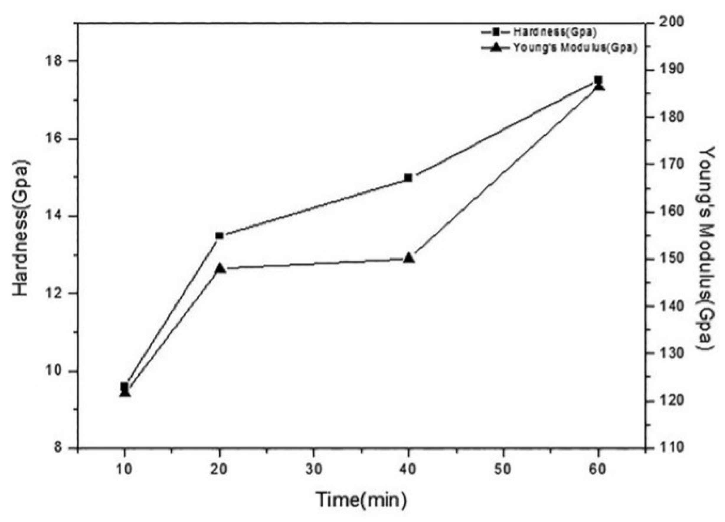
A significant increase in hardness and Young’s modulus of a material can be achieved by HEA-based coatings using the direct current (DC) MS technique. Li et al. [47] prepared a FeAlCuCrCoMn coating on a quartz glass wafer to investigate its mechanical behavior. EDS results show that the deposited film on the substrate is equimolar and has an amorphous structure (similar to the substrate’s structure) at the initial stage of the deposition, exhibiting lower hardness and Young’s modulus of 8.2 and 122 GPa, respectively. However, with an increase in deposition time, the thickness of the coating increases, and the film transforms to a FCC solid-solution structure as the substrate has less influence on the film structure, resulting in an increase in hardness and Young’s modulus to 17.5 and 186 GPa, respectively (see Figure 4). At plasma power below 80 W, the grain size on the coating surface is around 10 nm. More dense and smooth coatings were deposited at high plasma power (100 W). However, at 150 W, the particles coarsened, and the surface coating became looser and micro-holes started appearing, having a negative effect on the mechanical properties of the coating. The maximum film thickness was about 1.788 µm.
Zhang et al. [48] fabricated amorphous AlFeCoNiCuZrV coatings using the DC MS process. The sputtering was performed under Ar and O2 atmosphere to investigate the influence of the oxygen flow ratio, RO, on HEA thin film’s mechanical behavior and microstructure. With an increase in RO, the thickness and Young’s modulus of the thin film decreased, while the hardness of the film slightly increased (see Figure 5). HEA thin film remained an amorphous structure irrespective of the RO. The hardness and Young’s modulus were 11 and 182 GPa, respectively, at RO = 0%, and 13 and 163 GPa, respectively, at RO = 50%.
Braic et al. [37] successfully deposited (TiZrNbHfTa)N and (TiZrNbHfTa)C coatings on C45 and M2 steel substrates in Ar + N2 and Ar + CH4 atmospheres, respectively. The maximum hardness of nitride and carbide deposits was 33 and 28 GPa. Compared to HEA-nitrides, HEA-carbide had a low friction coefficient (µ = 0.15).
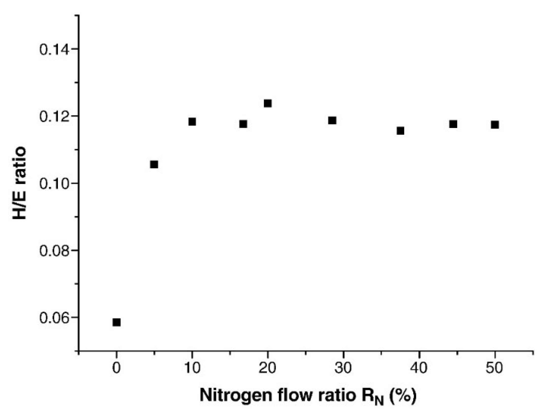
Huang and Yeh [38] investigated the effect of N content on the mechanical properties of AlCrNbSiTiV coatings on a Si wafer. The AlCrNbSiTiV thin film had an amorphous structure with hardness and Young’s modulus of 10.4 and 177 GPa, respectively. (AlCrNbSiTiV)N0.5 film could be synthesized with a RN above 10%. Even at RN = 5%, there was a significant increase in the hardness and Young’s modulus. The HEA-nitride film transformed to a FCC structure. At RN = 5%, the hardness and Young’s modulus ranged from 35 to 41 and 300 to 360 GPa, respectively. Maximum hardness and H/E (hardness/Young’s modulus) ratio were achieved when the RN was 20% (Figure 6) [38].
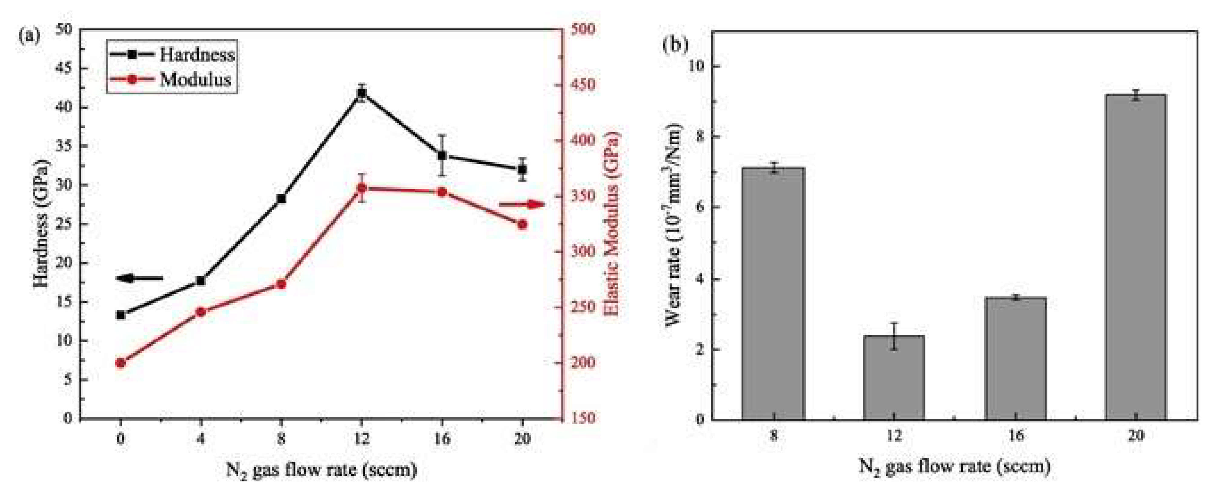
Xu et al. [49] prepared AlCrTiVZr nitride films on a Si wafer using high-power impulse magnetron sputtering at varying nitrogen flow rates (FN), from 0 to 20 sccm. The HEAN films reach a saturated state at and above 8 sccm. The hardness and modulus significantly increased from 13.3 and 199 to 42.5 and 355 GPA, respectively, when the FN rose to 12 from 0 sccm. The lowest wear rate of 2.3 × 10⁻⁷ mm3/Nm was recorded at FN = 12 sccm. Over the critical N2 flow rate (FN = 12 sccm), the bombardment of high-energy particles weakens due to the decrease in plasma energy, which results in the decline in hardness and Young’s modulus, and the increase in wear rate (see Figure 7).

3.2. Corrosion Resistance

Surface coating is an effective way to enhance the corrosion resistance of the substrate. It has been well-established that using HEA/HEAN thin layers on metal substrates can protect the substrate from corrosion. Studies suggest that Ni-rich HEA coatings demonstrate high corrosion resistance [50]. Computational studies suggest that Ni-rich HEA has a higher pitting resistance equivalent number (PREN), which reflects higher corrosion resistance. Ni59Cr22Fe3Mo16W3 exhibited low corrosion current density and more positive corrosion potential compared to Ni38Cr21Fe20Ru13Mo6 in 0.1 M Na2SO4 + H2SO4 (pH = 4); thus, higher Ni compositions promote corrosion resistance [50]. Moreover, Ni promotes the formation of a single FCC structure, which prevents galvanostatic corrosion and promotes the formation of Ni-based passive films, improving the corrosion resistance [51].
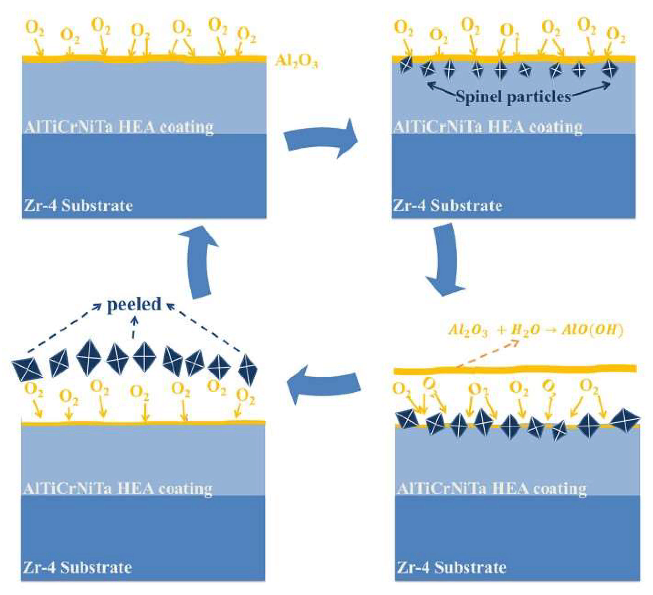
Zhao et al. [52] investigated the corrosion behavior of an AlTiCrNiTa coating fabricated on Zr-4 substrate using the radiofrequency (RF) MS technique. The corrosion process was studied by placing the HEA-coated specimen in an autoclave containing pure water with 1000 ppm boron and <10 ppm oxygen at 320 °C and a saturation pressure of 11.3 Mpa for 45 days. With an increase in corrosion time, there was an increase and a decrease in specimen weight. After the completion of the 45-day autoclave test, the coated samples’ weight loss was 10 mg/dm2, indicating the dissolution of the HEA coating. It has been suggested that the corrosion process was cyclic and layer-by-layer, as shown in Figure 8. In brief, Al present in the coating reacts with O2 and leads to the formation of Al2O3 as the outermost layer. Spinel NiCr2O4 particles are formed on the Al2O3 layer due to the contact of O2 with Cr. Al2O3 reacts with H2O, resulting in the formation of AlO(OH), leading to the dissolution of the Al2O3 layer, followed by peeling of NiCr2O4 particles. This would suggest that with time, the durability of the coating is reduced. The authors suggest that this problem can be solved by reducing the Al content to reduce the dissolution of Al2O3 and increasing the Cr content to promote the formation of a dense spinel NiCr2O4 coating.
Zhang et al. [42] fabricated a nearly equal molar ratio AlCrMoNbZr HEA coating on N36 zirconium alloy to improve the corrosion resistance of the substrate used in light water reactor fuel cladding. The coated substrate was immersed in static pure water at 360 °C at 18.7 MPa for 30 days. It was found that there was no N36 substrate oxide formation, indicating that the HEA coating successfully protected the substrate from corrosion. SEM examination reveals the formation of Nb2Zr6O17, Cr2O3 and ZrO2 protective oxide layers on the coating surface. Results suggest that the AlCrMoNbZr HEA coating is suitable for use as an accident-tolerant fuel (ATF) material to improve the corrosion resistance of Zr alloy used in fuel cladding.
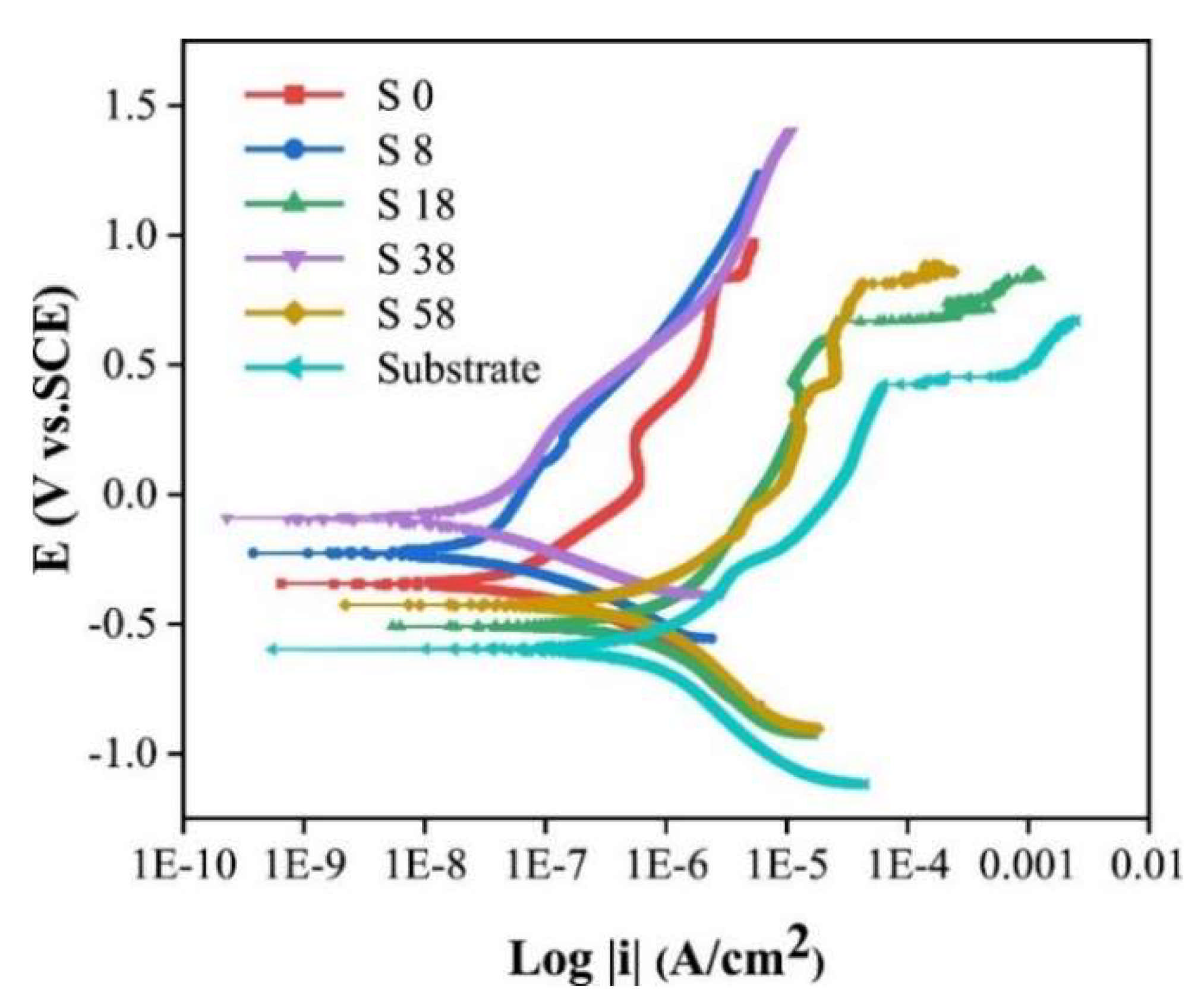
Zhang et al. [43] deposited a (CrNbTiAlV)Nx coating on AISI 440 C steel substrate using the MS method to examine the corrosion resistance (in 3.5 wt.% NaCl solution) of the coatings and the substrate. As shown in potentiodynamic polarization curves (Figure 9), compared with the substrate, all the films show a more positive corrosion potential and smaller corrosion current densities, implying better corrosion resistance. For the S0 sample, the uniform amorphous structure prevents the penetration of Cl ions and improves the corrosion resistance. A columnar structure is formed at low nitrogen concentrations on the film’s surface. The introduction of grain boundaries will act as a pathway for chloride ion diffusion, resulting in faster corrosion, to an extent. The authors reported that coatings deposited at appropriate FN could form a dense nanocrystalline structure, improving the corrosion resistance ability of the coatings. No pitting potentials were observed for S8 and S38 layers, which means excellent resistance towards penetration and pitting of chloride ions.
Gao et al. [53] prepared a CoCrFeNiAl0.3 HEA thin coating on a silicon substrate using the RF MS process. The corrosion behavior of the HEA thin film was examined by performing potentiodynamic polarization on the coated substrate in a 3.5 wt.% NaCl solution at room temperature. Results show that the CoCrFeNiAl0.3 HEA thin coating has a significantly lower corrosion rate than a silicon substrate.
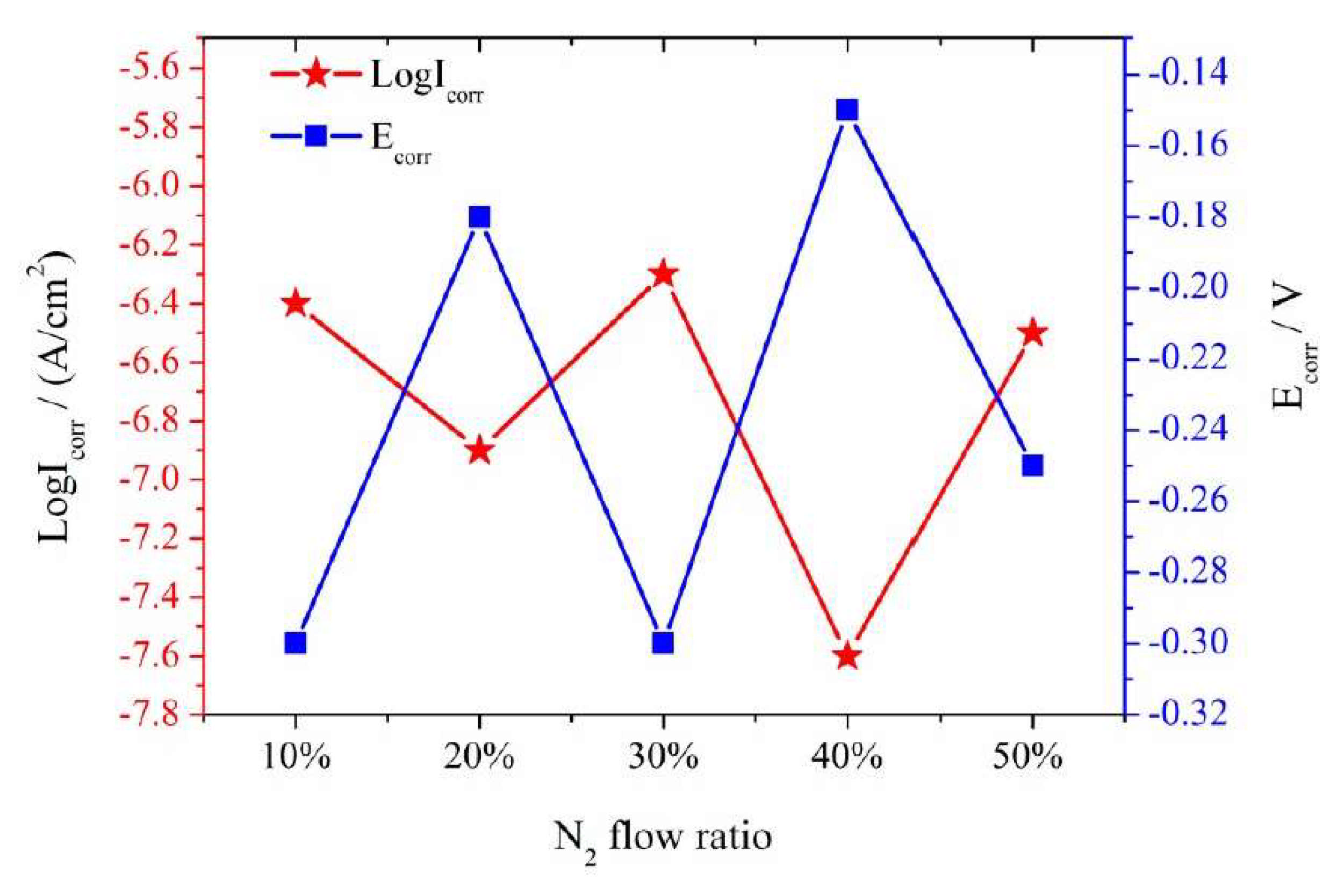
Xing et al. [54] prepared a (NbTiAlSiZr)(100−x)Nx coating using the MS technique on 304 stainless-steel by varying N2 flow rates between 0% and 50% (with an increment of 10%). Electrochemical potentiometric electrode polarization of the 304 stainless-steel (304 SS) substrate with the HEA nitride coating was performed in 0.5 mol/L of H2SO4 etching solution to study the corrosion resistance of the HEAN coating. It was found that the thin films prepared with an N2 flow rate of 10% and 30% have higher corrosion rates than the 304 SS substrate, while the HEAN thin films synthesized from 20%, 40% and 50% N2 flow rates have lower corrosion rates compared to 304 SS substrates. When the N2 flow rate was 20%, the N2 interacted with the metals, forming a strong covalent bond and improving the corrosion resistance. However, with an increase in N2 flow rate to 30%, the homogeneity of (NbTiAlSiZr)(100−x)Nx was disturbed, leading to high corrosion rates compared to the substrate (Figure 10).

3.3. Thermal Stability and Oxidation Resistance

Recent research shows that HEA thin films also possess excellent thermal stability and superior oxidation resistance, similar to bulk HEA materials. Sheng et al. [55] studied the thermal stability of (NbTiAlSiW)xNy thin films. The structure of the thin films remained amorphous even after heating at 700 °C for 24 h. However, after 1 h of heat treatment at 1000 °C, an amorphous structure of the thin film was transformed to a crystallized structure (BCC or FCC) with homogeneous nano-scaled grains. The metallic film had a BCC solid-solution structure with no N2 flow. The thin film’s structure was influenced by Nb and W elements as they possess a BCC structure. With an increase in N2 flow rate, the nitride film was transformed to an FCC structure. This transformation to FCC can be attributed to NbN and TiN inter-metallics with FCC structure formed during the heat treatment. Shen et al. [56] studied the oxidation resistance of a (Al0.34Cr0.22Nb0.11Si0.11Ti0.22)50N50 thin film coated on a Si wafer by the MS method. The coatings were deposited at RN = 50%, with a substrate temperature of 415 °C, a bias voltage of −100 V and the sputtering power was kept at 150 W. The oxide layer thickness of the HEAN coating after annealing at 900 °C for 50 h was only 290 nm. The mass gain after oxidizing the HEAN coating at 1300 °C was 0.0015 mg.cm2. The oxide layer was composed of eight different oxide structures, which would slow down the O2 diffusion and increase the oxidation resistance of the substrate. The outermost layer, Al2O3, played a crucial role in enhancing the oxidation resistance of the coating. One of the main reasons for the improved oxidation resistance is attributed to the Nb-containing SiO2-rich layer, which reduces the number of vacancies and slows down the diffusion of oxygen atoms. Kretschmer et al. [57] investigated the oxidation resistance of (AlCrNbTaTi)N and Si-doped (AlCrNbTaTi)N thin films prepared by the MS method on Si and sapphire substrates. The (AlCrNbTaTi)N film had an FCC structure, and decomposition of the FCC structure only occurred when the annealing temperature reached 1000 °C. Decomposition temperature shifted to 1200 °C when 12.0 at.% of Si was introduced to the HEA film composition, which means that Si-doping can further improve the oxidation resistance of HEA films. A similar phenomenon was observed by Tsai et al. [58], where the oxidation resistance of (AlCrMoTaTi)N enhanced with the addition of Si 7.51 at.%. This could be due to the presence of SiO2 amorphous structure as an outer layer, which improves the oxidation resistance.

3.4. Diffusion Retardation

HEA-based coatings have been considered as diffusion barrier materials due to their excellent mechanical behavior, high corrosion resistance and limited diffusion kinetics. HEA and HEA-nitride-based coatings can be an intermediate connection in circuits. For instance, the HEA-nitride interlayer between the Cu and Si in circuits can act as a successful diffusion barrier. Tsai et al. [59] reported that the AlMoNbSiTaTiVZr thin layer (thickness of 100 nm) successfully performed as an effective diffusion barrier between Cu and Si. The HEA thin layer prevented Cu-silicide formation when Cu/AlMoNbSiTaTiVZr/Si was annealed at 700 °C for 30 min. However, when annealed at 750 °C, the Cu penetrates into Si and forms Cu-silicide. Chang and Chen [60] prepared an ultrathin (AlCrTaTiZr)N interlayer with a thickness of 10 nm. The HEA-N interlayer acts as a diffusion barrier for Cu interconnects. The Si/(AlCrTaTiZr)N/Cu film stack was exposed to an extremely high temperature of 900 °C, and it was observed that the HEAN nanofilm was thermally stable and acted successfully as a diffusion barrier, with no Cu-silicide found on the Si surface. The HEAN coating’s excellent diffusion retardation behavior is attributed to its simple solid-solution structure, high packing density and low free volume.
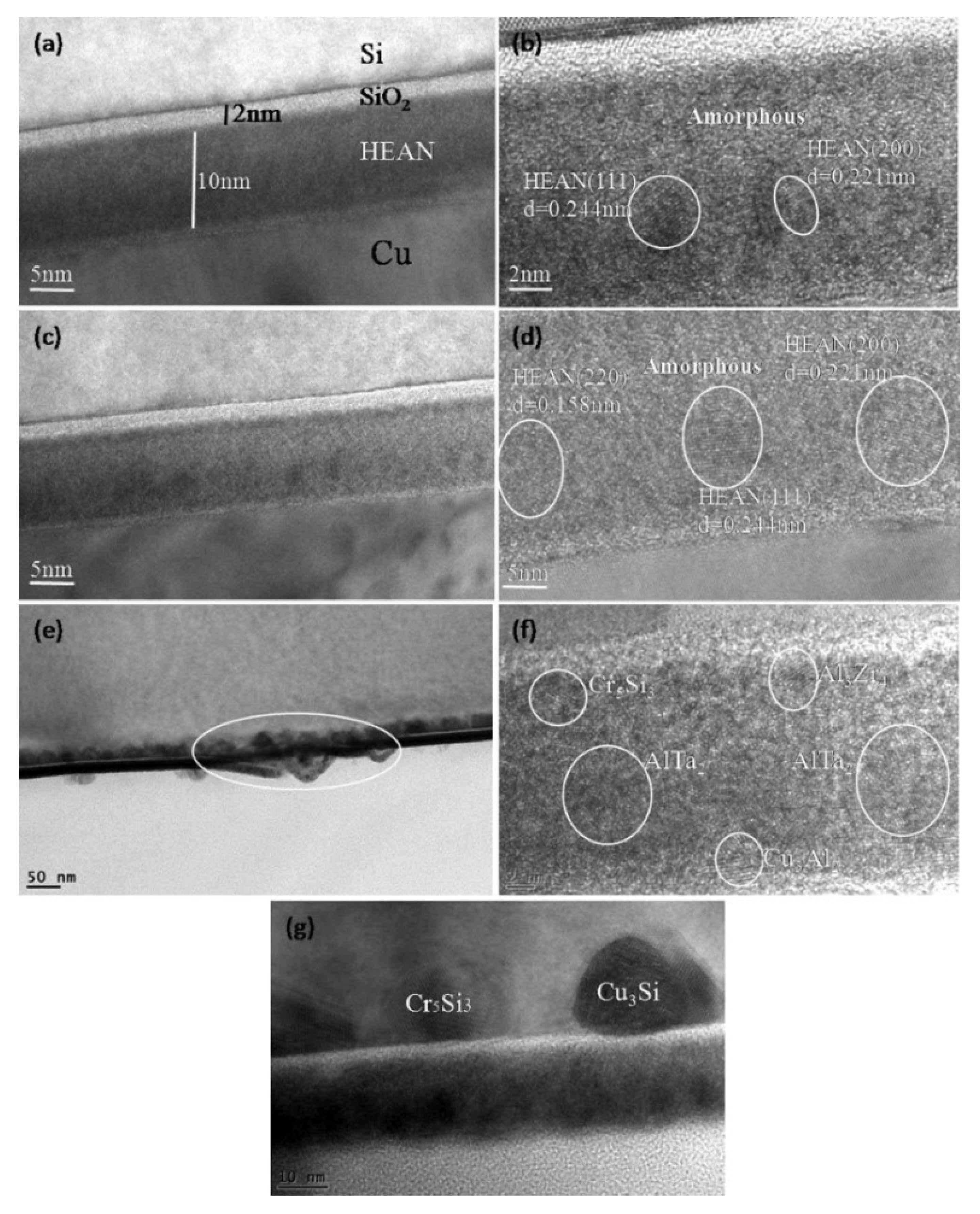
Li et al. [61] fabricated a multi-component AlCrTaTiZrRu/(AlCrTaTiZrRu)N0.7 double-layer coating as a diffusion barrier for Cu interconnection using the MS process. Cu(50 nm)/AlCrTaTiZrRu(3 nm)/(AlCrTaTiZrRu)N0.7(10 nm)/Si structures were annealed between 700 and 900 °C to examine the diffusion barrier properties of the thin multi-component intermediate coating. The nanocomposite structure of the HEA/HEAN multilayer remained unchanged after the annealing at temperatures below 800 °C. No Cu-silicides were found on the HEAN or the Si surface, indicating that the HEA/HEAN thin films successfully functioned as diffusion barriers. However, at a high annealing temperature of 900 °C, Cu-silicides and other inter-metallics were found on the surface of Cu films, meaning complete failure of multilayer HEA thin films as diffusion barriers at temperatures above 800 °C. Li et al. [62] prepared a Cu/(AlCrTaTiZrMo)N/Si structure (Figure 11a,b) and performed annealing between 700 and 900 °C in a vacuum for 1 h. Under annealing temperatures below 800 °C, the HEAN layer remained amorphous with a nanocrystalline structure, effectively acting as a diffusion barrier between Cu and Si with no Cu-silicide presence (see Figure 11c,d). However, in structures annealing at 900 °C, the Cu-silicide and other inter-metallics were found on HEAN layers, meaning interdiffusion occurred between Cu and Si (see Figure 11e–g).
Chang et al. [63] reported that (AlCrTaTiZr)N can act as an effective diffusion barrier between Cu and Si, even at temperatures of around 900 °C, by increasing the HEAN layer thickness to 50 nm. The excellent diffusion barrier ability of HEA and HEAN thin films is attributed to the lattice distortion due to the difference in atoms’ radii, nanocomposite structures surrounded by the amorphous matrix without any grain boundaries and the high stacking density without rapid diffusion pathways.
Xu et al. [64] prepared an AlCoCrNiMo thin film using direct current magnetron sputtering, which acts as an interlayer between the NiAlHf protective coating and the Ni-based super-crystal superalloy. Isothermal oxidation at 1100 °C was performed on the NiAlHf/HEA/Ni-based superalloy structure to examine the interdiffusion behavior and high-temperature oxidation resistance. The sputtering parameters were: a working temperature of 200 °C, working pressure of 0.8 Pa, sputtering power of 300 W and a bias voltage of −100 V. The HEA film thickness was 4 µm. Results suggest that the HEA intermediate layer performed well as a diffusion barrier as no interdiffusion zone or any other intermetallic phases were observed after the NiAlHf/HEA/Ni-based superalloy structure was exposed to high temperatures. Moreover, the corrosion resistance of the NiAlHf protective layer was enhanced with the inclusion of HEA thin film as an intermediate layer. The sluggish diffusion effect of HEA films is attributed to minimizing interlayer diffusion, making them effective diffusion barriers. Moreover, the formation of the Al2O3 layer between the NiAlHf/HEA and HEA/Ni enhanced the high-temperature oxidation resistance of NiAlHf. The Co element in the HEA barrier helps in suppressing the formation of secondary reaction zones and topologically close-packed precipitates in Ni-super alloys by stabilizing the γ/γ’ matrix.

3.5. Wear Resistance

HEA coatings are considered to have better wear resistance compared to other alloy coatings at a wide range of temperatures, making HEA coatings a suitable candidate for tribological applications. Tuten et al. [32] fabricated TiTaHfNbZr thin films on a biomedical Ti-6Al-4V substrate using the RF MS technique. The coefficient of friction (COF) with varying sliding distances was evaluated at three different loads (1, 2 and 3 N). For an applied load of 1 N, the COF of TiTaHfNbZr thin films (≈800 nm) was in the range of 0.05 to 0.1, while the COF of Ti-6Al-4V was 0.3 to 0.35. Visible wear marks were observed on the Ti-6Al-4V surface at an applied load of 3 N, however, no visible wear marks were seen on the TiTaHfNbZr thin film’s surface. The superior hardness and elasticity of HEA thin films contributed to their high wear resistance. The authors suggest that Ti-6Al-4V material with a TiTaHfNbZr coating can be used for long-term orthopedic implants.
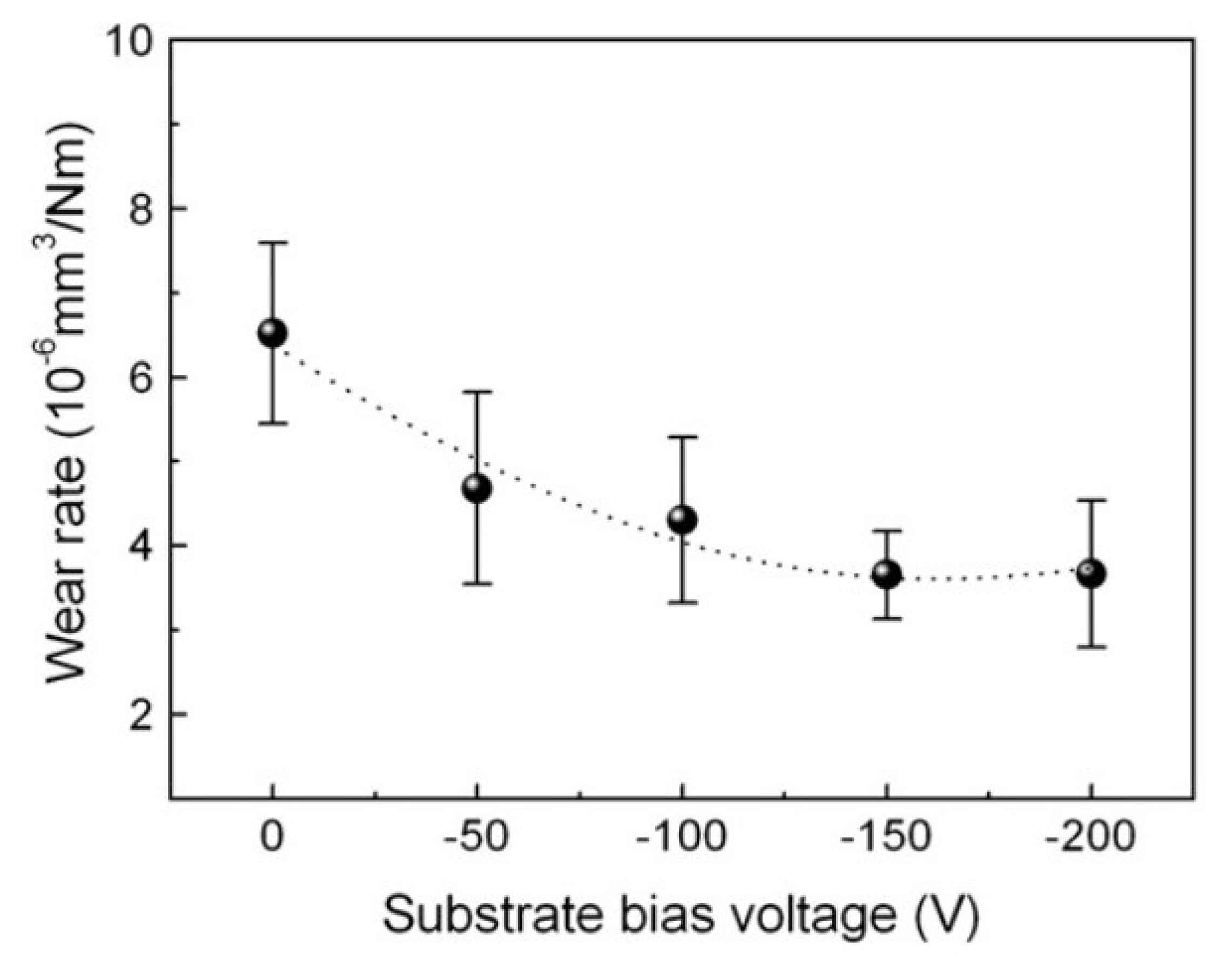
Lai et al. [45] fabricated (AlCrTaTiZr)N thin films on Si substrate using the RF MS technique. As shown in Figure 12, the wear rate of the coating decreases with an increase in substrate bias voltage. On the other hand, bias voltage did not affect the COF (constant value 0.75) of the coatings. The lowest wear rate of 3.66 × 10⁻⁶ mm3/Nm was recorded when the substrate bias voltage was −150 V. A lower wear rate at a high bias voltage is attributed to the high hardness and cohesive strength of the coatings caused by the enhanced ion-bombarding effect.
Luo et al. [65] prepared multilayer self-lubricating NbMoWTa/Ag thin films using the MS technique and investigated their wear resistance. Tribological properties of NbMoWTa/Ag multilayer films were investigated at different individual layer thicknesses (h). The wear rate and COF of NbMoWTa/Ag multilayer films decreased with the decrease of h from 100 to 2.5 nm. The multilayer films with h = 2.5 nm possess high hardness and better wear resistance compared to monolithic NbMoWTa films. This is mainly contributed by the transition of the deformation mechanism from classic Hall–Petch strengthening to coherent strengthening for NbMoWTa/Ag multilayers with the decrease in h. At h = 2.5 nm, the layers are highly coherent with the self-lubricating ability and the wear rate of the multilayer film was 9 × 10⁻⁶ mm3/Nm.

4. Concluding Remarks

This paper briefly discussed the HEA-based thin layers deposited by the magnetron sputtering method. The main parameters that influence the properties of coatings are target composition, bias voltage and gas flow rate. MS HEA coatings exhibit excellent properties, such as high hardness and Young’s modulus, excellent corrosion and wear resistance, thermal stability at elevated temperatures and diffusion retardation. HEA coatings have shown excellent wear resistance and can be used as coatings on orthopedic implants to prolong their lifetime. The properties of HEA coatings can be further enhanced with nitrogen doping, as the structure of HEA coatings transforms from amorphous to FCC. The HEA-nitride coatings have better mechanical properties and corrosion resistance than metallic HEA thin films, owing to the FCC structure of HEA-nitride coatings. HEAN thin films have superior corrosion resistance and can eliminate the pitting effect when used as protective coatings for ships. HEAN intermediate coatings can act as diffusion barriers in Cu interconnection in circuits. The HEAN thin films have excellent thermal stability, as the structure remains unchanged when exposed to high temperatures. However, it is worth noting that HEA coatings show better corrosion resistance compared to HEAN coatings when the HEAN coatings are not fabricated at optimal N2 flow rates. Moreover, metallic HEA coatings show excellent diffusion barrier behavior at temperatures below 750 °C.

Author Contributions

Conceptualization, S.K.P.; methodology, S.K.P.; validation, A.Y., V.Y. and G.S.; investigation, S.K.P.; writing—original draft preparation, S.K.P.; writing—review and editing, A.Y., V.Y. and G.S.; supervision, G.S.; project administration, A.Y., funding acquisition, A.Y. All authors have read and agreed to the published version of the manuscript.

Funding

The work was performed as a part of the State Assignment for the Science of Siberian Federal University (No. FSRZ-2020-0013). Use of Krasnoyarsk Regional Center of Research Equipment of Federal Research Center “Krasnoyarsk Science Center SB RAS” is acknowledged.

Conflicts of Interest

The authors declare no conflict of interest.

References

  1. Yeh, J.W.; Chen, S.K.; Lin, S.J.; Gan, J.Y.; Chin, T.S.; Shun, T.T.; Tsau, C.H.; Chang, S.Y. Nanostructured High-Entropy Alloys with Multiple Principal Elements: Novel Alloy Design Concepts and Outcomes. Adv. Eng. Mater. 2004, 6, 299–303. [Google Scholar] [CrossRef]
  2. Xu, X.D.; Guo, S.; Nieh, T.G.; Liu, C.T.; Hirata, A.; Chen, M.W. Effects of mixing enthalpy and cooling rate on phase formation of AlxCoCrCuFeNi high-entropy alloys. Materialia 2019, 6, 100292. [Google Scholar] [CrossRef]
  3. Wang, W.R.; Wang, W.L.; Wang, S.C.; Tsai, Y.C.; Lai, C.H.; Yeh, J.W. Effects of Al addition on the microstructure and mechanical property of AlxCoCrFeNi high-entropy alloys. Intermetallics 2012, 26, 44–51. [Google Scholar] [CrossRef]
  4. Tsai, M.H.; Yeh, J.W. High-entropy alloys: A critical review. Mater. Res. Lett. 2014, 2, 107–123. [Google Scholar] [CrossRef]
  5. Otto, F.; Dlouhý, A.; Somsen, C.; Bei, H.; Eggeler, G.; George, E.P. The influences of temperature and microstructure on the tensile properties of a CoCrFeMnNi high-entropy alloy. Acta Mater. 2013, 61, 5743–5755. [Google Scholar] [CrossRef] [Green Version]
  6. Munitz, A.; Kaufman, M.; Nahmany, M.; Derimow, N.; Abbaschian, R. Microstructure and mechanical properties of heat-treated Al1. 25CoCrCuFeNi high entropy alloys. Mater. Sci. Eng. A 2018, 714, 146–159. [Google Scholar] [CrossRef]
  7. Chuang, M.H.; Tsai, M.H.; Wang, W.R.; Lin, S.J.; Yeh, J.W. Microstructure and wear behavior of AlxCo1.5CrFeNi1.5Tiy high-entropy alloys. Acta Mater. 2011, 59, 6308–6317. [Google Scholar] [CrossRef]
  8. Chen, Y.; Duval, T.; Hung, U.; Yeh, J.; Shih, H. Microstructure and electrochemical properties of high entropy alloys—A comparison with type-304 stainless steel. Corros. Sci. 2005, 47, 2257–2279. [Google Scholar] [CrossRef]
  9. Gludovatz, B.; Hohenwarter, A.; Catoor, D.; Chang, E.H.; George, E.P.; Ritchie, R.O. A fracture-resistant high-entropy alloy for cryogenic applications. Science 2014, 345, 1153–1158. [Google Scholar] [CrossRef] [PubMed] [Green Version]
  10. Gao, M.C.; Yeh, J.W.; Liaw, P.K.; Zhang, Y. (Eds.) High-Entropy Alloys: Fundamentals and Applications; Springer: Cham, Switzerland, 2016; 524p. [Google Scholar]
  11. Zhou, Y.; Zhang, Y.; Wang, Y.; Chen, G. Microstructure and Compressive Properties of Multicomponent Alx(TiVCrMnFeCoNiCu)100-x High-Entropy Alloys. Mater. Sci. Eng. A 2007, 454–455, 260–265. [Google Scholar] [CrossRef]
  12. Zhang, Y.; Lu, Z.P.; Ma, S.G.; Liaw, P.K.; Tang, Z.; Cheng, Y.Q.; Gao, M.C. Guidelines in predicting phase formation of high-entropy alloys. MRS Commun. 2014, 4, 57–62. [Google Scholar] [CrossRef]
  13. Li, J.; Huang, Y.; Meng, X.; Xie, Y. A Review on High Entropy Alloys Coatings: Fabrication Processes and Property Assessment. Adv. Eng. Mater. 2019, 21, 1900343. [Google Scholar] [CrossRef]
  14. Ni, C.; Shi, Y.; Liu, J.; Huang, G. Characterization of Al0.5FeCu0.7NiCoCr high-entropy alloy coating on aluminum alloy by laser cladding. Opt. Laser Technol. 2018, 105, 257–263. [Google Scholar] [CrossRef]
  15. Shon, Y.; Joshi, S.S.; Katakam, S.; Rajamure, R.S.; Dahotr, N.B. Laser additive synthesis of high entropy alloy coating on aluminum: Corrosion behavior. Mater. Lett. 2015, 142, 122–125. [Google Scholar] [CrossRef]
  16. Li, W.; Liu, P.; Liaw, P.W. Microstructures and properties of high-entropy alloy films and coatings: A review. Mater. Res. Lett. 2018, 6, 199–229. [Google Scholar] [CrossRef] [Green Version]
  17. Chang, S.; Li, C.; Chiang, S.; Huang, Y. 4-nm thick multilayer structure of multi-component (AlCrRuTaTiZr)Nx as robust diffusion barrier for Cu interconnects. J. Alloys Compd. 2012, 515, 4–7. [Google Scholar] [CrossRef]
  18. Lin, S.; Chang, S.; Huang, Y.; Shieu, F.; Yeh, J. Mechanical performance and nanoindenting deformation of (AlCrTaTiZr)NCy multi-component coatings co-sputtered with bias. Surf. Coat. Technol. 2012, 206, 5096–5102. [Google Scholar] [CrossRef]
  19. Meghwal, A.; Anupam, A.; Murty, B.S.; Berndt, C.C.; Kottada, R.S.; Ang, A.S.M. Thermal Spray High-Entropy Alloy Coatings: A Review. J. Therm. Spray Tech. 2020, 29, 857–893. [Google Scholar] [CrossRef]
  20. Calderon Velasco, S.; Cavaleiro, A.; Carvalho, S. Functional properties of ceramic-Ag nanocomposite coatings produced by magnetron sputtering. Prog. Mater. Sci. 2016, 84, 158–191. [Google Scholar] [CrossRef] [Green Version]
  21. Frey, H.; Khan, H.R. Handbook of Thin Film Technology; Springer: Cham, Switzerland, 2010; 380p. [Google Scholar]
  22. Golosov, D.A. Balanced magnetic field in magnetron sputtering systems. Vacuum 2017, 139, 109–116. [Google Scholar] [CrossRef]
  23. Schwarz, H.; Uhlig, T.; Rösch, N.; Lindner, T.; Ganss, F.; Hellwig, O.; Lampke, T.; Wagner, G.; Seyller, T. CoCrFeNi High-Entropy Alloy Thin Films Synthesised by Magnetron Sputter Deposition from Spark Plasma Sintered Targets. Coatings 2021, 11, 468. [Google Scholar] [CrossRef]
  24. Cemin, F.; Jimenez, M.J.M.; Leidens, L.M.; Figueroa, C.A.; Alvarez, F. A thermodynamic study on phase formation and thermal stability of AlSiTaTiZr high-entropy alloy thin films. J. Alloys Compd. 2020, 838, 155580. [Google Scholar] [CrossRef]
  25. Cemin, F.; de Mello, S.R.S.; Figueroa, C.A.; Alvarez, F. Influence of substrate bias and temperature on the crystallization of metallic NbTaTiVZr high-entropy alloy thin films. Surf. Coat. Technol. 2021, 421, 127357. [Google Scholar] [CrossRef]
  26. Khan, N.A.; Akhavan, B.; Zhou, C.; Zhou, H.; Chang, L.; Wang, Y.; Liu, Y.; Fu, L.; Bilek, M.M.; Liu, Z. RF magnetron sputtered AlCoCrCu0.5FeNi high entropy alloy (HEA) thin films with tuned microstructure and chemical composition. J. Alloys Compd. 2020, 836, 155348. [Google Scholar] [CrossRef]
  27. Huang, P.K.; Yeh, J.W. Effects of substrate temperature and post-annealing on microstructure and properties of (AlCrNbSiTiV)N coatings. Thin Solid Films 2009, 518, 180–184. [Google Scholar] [CrossRef]
  28. Shaginyan, L.R.; Gorban, V.F.; Krapivka, N.A.; Firstov, S.A.; Kopylov, I.F. Properties of Coatings of the Al–Cr–Fe–Co–Ni–Cu–V High Entropy Alloy Produced by the Magnetron Sputtering. J. Superhard. Mater. 2016, 38, 25–33. [Google Scholar] [CrossRef]
  29. Cheng, K.H.; Lai, C.H.; Lin, S.J.; Yeh, J.W. Structural and mechanical properties of multi-element (AlCrMoTaTiZr)Nx coatings by reactive magnetron sputtering. Thin Solid Films 2011, 519, 3185–3190. [Google Scholar] [CrossRef]
  30. Kao, W.H.; Su, Y.L.; Horng, J.H.; Wu, H.M. Effects of carbon doping on mechanical, tribological, structural, anti-corrosion and anti-glass-sticking properties of CrNbSiTaZr high entropy alloy coatings. Thin Solid Films 2021, 717, 138448. [Google Scholar] [CrossRef]
  31. Liao, W.B.; Zhang, H.; Liu, Z.Y.; Li, P.F.; Huang, J.J.; Yu, C.Y.; Lu, Y. High Strength and Deformation Mechanisms of Al0.3CoCrFeNi High-Entropy Alloy Thin Films Fabricated by Magnetron Sputtering. Entropy 2019, 21, 146. [Google Scholar] [CrossRef] [PubMed] [Green Version]
  32. Tüten, N.; Canadinc, D.; Motallebzadeh, A.; Bal, B. Microstructure and tribological properties of TiTaHfNbZr high entropy alloy coatings deposited on Ti−6Al−4V substrates. Intermetallics 2019, 105, 99–106. [Google Scholar] [CrossRef]
  33. Yu, X.; Wang, J.; Wang, L.; Huang, W. Fabrication and characterization of CrNbSiTiZr high-entropy alloy films by radio-frequency magnetron sputtering via tuning substrate bias. Surf. Coat. Technol. 2021, 412, 127074. [Google Scholar] [CrossRef]
  34. Zeng, Q.; Xu, Y. A comparative study on the tribocorrosion behaviors of AlFeCrNiMo high entropy alloy coatings and 304 stainless steel. Mater. Today Commun. 2020, 24, 101261. [Google Scholar] [CrossRef]
  35. Chang, H.W.; Huang, P.K.; Davison, A.; Yeh, J.W.; Tsau, C.H.; Yang, C.C. Nitride films deposited from an equimolar Al–Cr–Mo–Si–Ti alloy target by reactive direct current magnetron sputtering. Thin Solid Films 2008, 516, 6402–6408. [Google Scholar] [CrossRef]
  36. Lin, C.H.; Duh, J.G. Corrosion behavior of (Ti–Al–Cr–Si–V)xNy coatings on mild steels derived from RF magnetron sputtering. Surf. Coat. Technol. 2008, 203, 558–561. [Google Scholar] [CrossRef]
  37. Braic, V.; Vladescu, A.; Balaceanu, M.; Luculescu, C.R.; Braic, M. Nanostructured multi-element (TiZrNbHfTa)N and (TiZrNbHfTa)C hard coatings. Surf. Coat. Technol. 2012, 211, 117–121. [Google Scholar] [CrossRef]
  38. Huang, P.K.; Yeh, J.W. Effects of nitrogen content on structure and mechanical properties of multi-element (AlCrNbSiTiV)N coating. Surf. Coat. Technol. 2009, 203, 1891–1896. [Google Scholar] [CrossRef]
  39. Johansson, K.; Riekehr, L.; Fritze, S.; Lewin, E. Multicomponent Hf-Nb-Ti-V-Zr nitride coatings by reactive magnetron sputter deposition. Surf. Coat. Technol. 2018, 349, 529–539. [Google Scholar] [CrossRef]
  40. Ren, B.; Shen, Z.; Liu, Z. Structure and mechanical properties of multi-element (AlCrMnMoNiZr)Nx coatings by reactive magnetron sputtering. J. Alloys Compd. 2013, 560, 171–176. [Google Scholar] [CrossRef]
  41. Kao, W.H.; Su, Y.L.; Horng, J.H.; Wu, W.C. Mechanical, tribological, anti-corrosion and anti-glass sticking properties of high-entropy TaNbSiZrCr carbide coatings prepared using radio-frequency magnetron sputtering. Mater. Chem. Phys. 2021, 268, 124741. [Google Scholar] [CrossRef]
  42. Zhang, W.; Tang, R.; Yang, Z.B.; Liu, C.H.; Chang, H.; Yang, J.J.; Liao, J.L.; Yang, Y.Y.; Liu, N. Preparation, structure, and properties of an AlCrMoNbZr high-entropy alloy coating for accident-tolerant fuel cladding. Surf. Coat. Technol. 2018, 347, 13–19. [Google Scholar] [CrossRef]
  43. Zhang, C.; Lu, X.; Wang, C.; Sui, X.; Wang, Y.; Zhou, H.; Hao, J. Tailoring the microstructure, mechanical and tribocorrosion performance of (CrNbTiAlV)N x high-entropy nitride films by controlling nitrogen flow. J. Mater. Sci. Technol. 2022, 107, 172–182. [Google Scholar] [CrossRef]
  44. Chang, Z.C.; Liang, J.Y. Oxidation Behavior and Structural Transformation of (CrTaTiVZr)N Coatings. Coatings 2020, 10, 415. [Google Scholar] [CrossRef]
  45. Lai, C.H.; Cheng, K.H.; Lin, S.J.; Yeh, J.W. Mechanical and tribological properties of multi-element (AlCrTaTiZr)N coatings. Surf. Coat. Technol. 2008, 202, 3732–3738. [Google Scholar] [CrossRef]
  46. Behravan, N.; Farhadizadeh, A.; Ghasemi, S.; Khademi, A.; Shojaei, H.; Ghomi, H. The pressure dependence of structure and composition of sputtered AlCrSiTiMoO high entropy thin film. J. Alloys Compd. 2021, 852, 156421. [Google Scholar] [CrossRef]
  47. Li, X.; Zheng, Z.; Dou, D.; Li, J. Microstructure and Properties of Coating of FeAlCuCrCoMn High Entropy Alloy Deposited by Direct Current Magnetron Sputtering. Mater. Res. 2016, 19, 802–806. [Google Scholar] [CrossRef] [Green Version]
  48. Zhang, J.; Zhu, J.B.; Sun, Z.Y.; Li, J.C. Preparation of Amorphous Coatings of AlFeCoNiCuZrV Alloy by Direct Current Magnetron Sputtering Method. Asian J. Chem. 2014, 26, 5627–5630. [Google Scholar] [CrossRef]
  49. Xu, Y.; Li, G.; Xia, Y. Synthesis and characterization of super-hard AlCrTiVZr high-entropy alloy nitride films deposited by HiPIMS. Appl. Surf. Sci. 2020, 523, 146529. [Google Scholar] [CrossRef]
  50. Lu, P.; Saal, J.E.; Olson, G.B.; Li, T.; Swanson, O.J.; Frankel, G.S.; Gerard, A.Y.; Quiambao, K.F.; Scully, J.R. Computational materials design of a corrosion resistant high entropy alloy for harsh environments. Scr. Mater. 2018, 153, 19–21. [Google Scholar] [CrossRef]
  51. Dou, D.; Li, X.C.; Zheng, Z.Y.; Li, J.C. Coatings of FeAlCoCuNiV high entropy alloy. Surf. Eng. 2016, 32, 766–770. [Google Scholar] [CrossRef]
  52. Zhao, S.; Liu, C.; Yang, J.; Zhang, W.; He, L.; Zhang, R.; Yang, H.; Wang, J.; Long, J.; Chang, H. Mechanical and high-temperature corrosion properties of AlTiCrNiTa high entropy alloy coating prepared by magnetron sputtering for accident-tolerant fuel cladding. Surf. Coat. Technol. 2021, 417, 127228. [Google Scholar] [CrossRef]
  53. Gao, L.; Liao, W.; Zhang, H.; Surjadi, J.U.; Sun, D.; Lu, Y. Microstructure, Mechanical and Corrosion Behaviors of CoCrFeNiAl0.3 High Entropy Alloy (HEA) Films. Coatings 2017, 7, 156. [Google Scholar] [CrossRef]
  54. Xing, Q.; Wang, H.; Chen, M.; Chen, Z.; Li, R.; Jin, P.; Zhang, Y. Mechanical Properties and Corrosion Resistance of NbTiAlSiZrNx High-Entropy Films Prepared by RF Magnetron Sputtering. Entropy 2019, 21, 396. [Google Scholar] [CrossRef] [PubMed] [Green Version]
  55. Sheng, W.; Yang, X.; Wang, C.; Zhang, Y. Nano-Crystallization of High-Entropy Amorphous NbTiAlSiWxNy Films Prepared by Magnetron Sputtering. Entropy 2016, 18, 226. [Google Scholar] [CrossRef]
  56. Shen, W.J.; Tsai, M.H.; Tsai, K.Y.; Juan, C.C.; Tsai, C.W.; Yeh, J.W.; Chang, Y.S. Superior Oxidation Resistance of (Al0.34Cr0.22Nb0.11Si0.11Ti0.22)50N50 High-Entropy Nitride. J. Electrochem. Soc. 2013, 160, C531–C534. [Google Scholar] [CrossRef]
  57. Kretschmer, A.; Kirnbauer, A.; Moraes, V.; Primetzhofer, D.; Yalamanchili, K.; Rudigier, H.; Mayrhofer, P.H. Improving phase stability, hardness, and oxidation resistance of reactively magnetron sputtered (Al,Cr,Nb,Ta,Ti)N thin films by Si-alloying. Surf. Coat. Technol. 2021, 416, 127162. [Google Scholar] [CrossRef]
  58. Tsai, D.C.; Deng, M.J.; Chang, Z.C.; Kuo, B.H.; Chen, E.C.; Chang, S.Y.; Shieu, F.S. Oxidation resistance and characterization of (AlCrMoTaTi)-Six-Ncoating deposited via magnetron sputtering. J. Alloys Compd. 2015, 647, 179–188. [Google Scholar] [CrossRef]
  59. Tsai, M.H.; Yeh, J.W.; Gan, J.Y. Diffusion barrier properties of AlMoNbSiTaTiVZr high-entropy alloy layer between copper and silicon. Thin Solid Films 2008, 516, 5527–5530. [Google Scholar] [CrossRef]
  60. Chang, S.Y.; Chen, D.S. 10-nm-thick quinary (AlCrTaTiZr)N film as effective diffusion barrier for Cu interconnects at 900 °C. Appl. Phys. Lett. 2009, 94, 231909. [Google Scholar] [CrossRef]
  61. Li, R.; Chen, T.; Jiang, C.; Zhang, J.; Zhang, Y.; Liaw, P.K. Applications of High Diffusion Resistance Multicomponent AlCrTaTiZrRu/(AlCrTaTiZrRu)N0.7 Film in Cu Interconnects. Adv. Eng. Mater. 2020, 22, 2000557. [Google Scholar] [CrossRef]
  62. Li, R.; Qiao, B.; Shang, H.; Zhang, J.; Jiang, C.; Zhang, W. Multi-component AlCrTaTiZrMo-nitride film with high diffusion resistance in copper metallization. J. Alloys Compd. 2018, 748, 258–264. [Google Scholar] [CrossRef]
  63. Chang, S.Y.; Chen, M.K.; Chen, D.S. Multiprincipal-Element AlCrTaTiZr-Nitride Nanocomposite Film of Extremely High Thermal Stability as Diffusion Barrier for Cu Metallization. J. Electrochem. Soc. 2009, 156, G37–G42. [Google Scholar] [CrossRef]
  64. Xu, Z.; Zhang, P.; Wang, W.; Shi, Q.; Yang, H.; Wang, D.; Hong, Y.; Wang, L.; Guo, C.; Lin, S.; et al. AlCoCrNiMo high-entropy alloy as diffusion barrier between NiAlHf coating and Ni-based single crystal superalloy. Surf. Coat. Technol. 2021, 414, 127101. [Google Scholar] [CrossRef]
  65. Luo, D.; Zhou, Q.; Ye, W.; Ren, Y.; Greiner, C.; He, Y.; Wang, H. Design and Characterization of self-lubricating refractory high entropy alloy based multilayered films. ACS Appl. Mater. Interfaces 2021, 13, 55712–55725. [Google Scholar] [CrossRef] [PubMed]
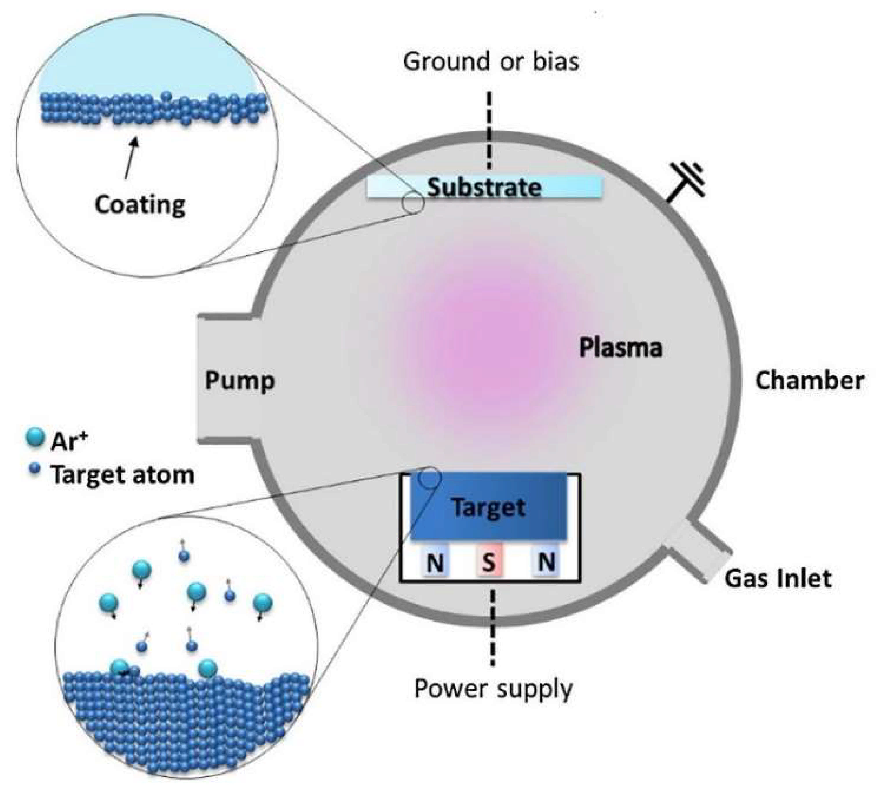
Figure 1. A schematic diagram of magnetron sputtering. Reproduced with permission from [20]. Copyright 2016, Elsevier.
Metals 12 00319 g001
Figure 2. (a) Balanced MS and (b) unbalanced MS schematic diagrams [N: North pole, S: South pole]. Reproduced with permission from [22]. Copyright 2016, Elsevier.
Metals 12 00319 g002
Figure 3. (a) Photograph of the AlSiTaTiZr multi-component “pizza-shaped” target used for the radio-frequency MS process, and (b) sputter yield for Ar+ ions at different energies impinging on the five elements present in the target. Reproduced with permission from [24]. Copyright 2020, Elsevier.
Metals 12 00319 g003
Figure 4. Hardness and Young’s modulus of the thin films with varying deposition time under 100 W plasma power [47] (Creative Commons Attribution 4.0 International License).
Metals 12 00319 g004
Figure 5. Variation in hardness and Young’s modulus with RO [48] (Creative Commons Attribution 4.0 International License).
Metals 12 00319 g005
Figure 6. H/E ratio of AlCrNbSiTiV nitride films deposited at different nitrogen flow ratios. Reproduced with permission from [38]. Copyright 2009, Elsevier.
Metals 12 00319 g006
Figure 7. (a) Hardness and Young’s modulus, and (b) wear rates of the (AlCrTiVZr)N films as a function of the FN. Reproduced with permission from [49]. Copyright 2009, Elsevier.
Metals 12 00319 g007
Figure 8. Schematic diagram of oxide peeling off during the corrosion process. Reproduced with permission from [52]. Copyright 2021, Elsevier.
Metals 12 00319 g008
Figure 9. Potentiodynamic polarization curves of the (CrNbTiAlV)Nx films at different nitrogen flow rates (in sccm) and substrate in artificial seawater at room temperature, where V is the corrosion potential and i is corrosion current density. Reproduced with permission from [43]. Copyright 2022, Elsevier.
Metals 12 00319 g009
Figure 10. Relationship between the self-corrosion potential (Ecorr) and the corrosion current density (Icorr) of NbTiAlSiZrNx HEA films with RN [54] (Creative Commons Attribution 4.0 International License).
Metals 12 00319 g010
Figure 11. (a,b) TEM cross-section image of the as-deposited Cu/(AlCrTaTiZrMo)N0.2/Si, (c,d) annealing at 800 °C and (e,f,g) annealing at 900 °C (circle: nanocrystalline lattices). Reproduced with permission from [62]. Copyright 2021, Elsevier.
Metals 12 00319 g011
Figure 12. The wear rates of the (AlCrTaTiZr)N thin films at varying substrate bias voltages. Reproduced with permission from [45]. Copyright 2008, Elsevier.
Metals 12 00319 g012
Table 1. Summary of HEA-based coating techniques [13,16,19].
TechniqueAdvantagesDisadvantages
Magnetron sputtering
  • Easy to obtain film stoichiometry similar to the stoichiometry of the target material
  • Rapid quenching of thin films at a rate of 109 K/s
  • Easy fabrication of superior mechanical ability and corrosion-resistant HEA nitride coatings
  • A slight variation in gas flow rate could drastically change the composition of HEA thin films
  • Time-consuming
Arc cladding
  • Low dilution of the substrate material
  • Excellent metallurgical bonding between substrate and coating
  • Low deposition coefficient
Laser cladding
  • Rapid solidification velocity (103–106 K/s), avoiding component segregation
  • Coatings with 1−5 mm thickness can be fabricated
  • Possible decline of the substrate and HEA coating properties due to elemental dilution
Thermal spraying
  • High deposition coefficient
  • Low dilution of coating materials
  • Highly porous films
  • Lamellar structure
Electrodeposition
  • Cost-efficient
  • Can fabricate coatings on complex geometries
  • Time-consuming
  • Contamination of coating from anode products
Table 2. The details about HEA-based coatings fabricated using magnetron sputtering.
CoatingsSubstratesPhasesThicknessHardnessRef.
(CrNbSiTaZr)CWCAmorphous1.2 − 2.1 µm6.53–20.12 GPa[30]
Al0.3CoCrFeNiSi waferFCC4.0 µm11.09 GPa[31]
TiTaHfNbZrTi-6Al-4VAmorphous0.8 µm12.51 GPa[32]
CrNbSiTiZrStainless steelAmorphous1.0 µm12.4 GPa[33]
AlFeCrNiMoStainless steelBCC1.5 µm-[34]
AlCrMoSiTiSi wafer and SiO2-SiAmorphous1.0 µm10–16 GPa[35]
(TiAlCrSiV)xNyMild steelAmorphous + FCC≈1.7 µm-[36]
(TiZrNbHfTa)NC45 steelFCC2.0 µm≈33 GPa[37]
(TiZrNbHfTa)NM2 steelFCC2.0 µm≈28 GPa[37]
(AlCrNbSiTiV)NSi waferAmorphous + FCC≈1.0 µm≈41 GPa[38]
(HfNbTiVZr)NSi wafer, α-SiO2, α-Al2O3FCC≈1.2 µm≈7.6–18.8 GPa[39]
(AlCrMnMoNiZr)NxSi waferFCC1.5 µm≈11.9 GPa[40]
(TaNbSiZrCr)CWC and SiFCC0.7–1.9 µm34.1 GPa[41]
AlCrMoNbZrN36 Zr alloyAmorphous + BCC3.0 µm11.8 GPa[42]
(CrNbTiAlV)NxAISI 440 C steelFCC0.67 µm49.95 GPa[43]
(CrTaTiVZr)NSi waferFCC1.0 µm34.3 GPa[44]
(AlCrTaTiZr)NSi and cemented carbide substrateFCC1.3 & 1.0 µm36.9 GPa[45]
AlCrSiTiMoOSiAmorphous3.3–3.8 µm8.9 GPa[46]
Publisher’s Note: MDPI stays neutral with regard to jurisdictional claims in published maps and institutional affiliations.