Abstract
Industrial tests and thermodynamic calculations were utilized to investigate the source and formation of magnetic particle inspection defects identified on the near-surface of the Cr5 back-up roll forged ingot, which was used in large cold rolling mills. The results showed that the linear aggregating SiO2-MnO-Al2O3 liquid inclusions up to 3 mm led to the flaw detection failure. SiO2-MnO-Al2O3 liquid inclusions were firstly formed in the inductive furnace. Due to its low contact angle, a huge amount of SiO2-MnO-Al2O3 liquid inclusions were inherited into the forged ingot. The formation of SiO2-MnO-Al2O3 liquid inclusions was attributed to the over-oxidation and relatively low aluminum content in the molten steel, as calculated by Factsage 8.1. Controlling the amount of aluminum in molten steel during the smelting process could modify the formation of SiO2-MnO-Al2O3 and CaO-SiO2-Al2O3 liquid oxide into solid Al2O3 type inclusions that were easily removed. Besides, the CaO-SiO2-Al2O3 liquid oxide could be transformed from CaO-Al2O3 type oxide by the significant loss of aluminum content during the VD process or slag entrapment. Certain content of aluminum in the molten steel could improve the flaw detection caused by the aggregating SiO2-MnO-Al2O3 inclusions effectively.
1. Introduction
In recent years, rolling mills have been making progress to meet the ever-increasing needs for high-quality steel products, particularly in China. Accordingly, the work roller and back-up roller are required to exhibit superior performance such as exceptional fatigue strength under high load and speed service conditions [1,2,3,4,5,6,7].
It is widely recognized that increasing Chromium content could reduce wear loss linearly [8,9,10,11]. Therefore, the chromium content of backup rollers has increased from 1.2% up to 3% and 5% in the 1970s [9,12,13]. The appearance of vacuum refining and electro-slag remelting (ESR) technology guaranteed the goal of high carbon with high alloy elements content and achieved the low hydrogen content [13,14]. Adding alloy elements like Mo, V, and W into backup rollers could also promote mechanical properties further as required. Nowadays, backup rollers were classified into Cr3 series and Cr5 series by their chromium content [8,9,15]. Non-destructive testing (NDT) technology, e.g., ultrasonic testing (UT), magnetic particle inspection (MPI), radiographic testing (RT), etc., have been widely used in the industry [16]. MPI was utilized frequently among these methods owing to the demanding requirements of surface and near-surface quality in rollers More and more defects were considered as metallurgical defects, which were caused by inclusions created in deoxidation, reactions between molten steel, slag and refractory, or even slag entrapment [17,18,19,20,21,22,23,24]. Jamil et al. [24] found that alumina and oxide types non-metallic inclusions caused the failure of ultrasonic testing in the sugar mill shaft. Lu et al. [25] found that large-sized, long-striped MnS inclusions were the major cause of the magnetic particle testing failure in the heavy truck crankshaft. Wang et al. [26] also found that the aggregation of single Al2O3 particles and Al2O3 clusters existed on the surface of 80 t 20Cr-8Ni stainless ingot, which failed the penetrating testing.
However, the studies aimed at promoting the properties of rollers were mainly around the after-casting manufacturing procedure, e.g., obtaining ideal characteristics of carbides, microstructure by heat treatment, etc. [27,28,29,30]. Meanwhile, few studies concerning the evolution and influence of inclusions in the large forged ingots were found [24]. Consequently, combined the appearance of ultrasonic defects on the post-forging rollers with the corresponding specimens during the plant steelmaking process, the origin, evolution, and improvement of defects have been analyzed and clarified. Besides, under the different deoxidation processes, the corresponding evolution and formation mechanism of oxide inclusions aided by thermodynamics calculation and plant trials were discussed as follows.
2. Materials and Methods
2.1. Experimental Procedure
The steelmaking process of 50ton Cr5 type backup roller could be briefly described as “induction furnace (IF) → ladle furnace (LF1) → ladle furnace (LF2) → vacuum degasser (VD) → ladle furnace (LF3) → vacuum casting (VC)”, as shown in Figure 1 The return scrap and alloy raw materials were melted in the IF. Then the deoxidation, desulfurization, and composition adjustment took place in LF1, which served as a pre-refining procedure. After the LF2 refining process, the vacuum degasser mainly undertook to degas especially dehydrogenation. Afterward, LF3 was considered to fulfill the final composition adjustment and superheat degree requirements before vacuum casting. To trace the origin of the defects, we implemented the tracking and analysis during the whole metallurgical process. And the original deoxidizer was silicon-aluminum (Si-Al) complex deoxidizer (Si: 65% in mass%, Al: 25% in mass%).

Figure 1.
Schematic illustration of original metallurgical process and sampling.
Lollipop steel specimens quenched by water and slag were sampled at different smelting stages i.e., the end of IF smelting, the beginning and end of each LF refining process, the vacuum-breaking of VD, and the beginning of VC, which were named by their chronological order, respectively. The defective parts sampled after forging and fine machining were rechecked and illustrated by a magnetic particle flaw detector, which was processed into 15 mm × 15 mm × 15 mm cubes to achieve the defective location and characteristics by optical microscope, as shown in Figure 2. All the specimens in the smelting process were machined to 10 mm × 10 mm × 10 mm cubes for testing and analysis. Schematic illustrations of the metallurgical process and sampling were shown in Figure 1.
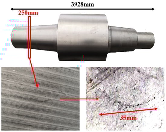
Figure 2.
Sampling and defective part characteristics on the roller.
2.2. Analysis Method of Composition and Micro-Inspection
The [Si], [Mn], [Al], [Ca] contents in molten steel were determined by inductively coupled plasma optical emission spectrometer method (ICP-OES). (ThermoFisher, Waltham, MA, USA) The total oxygen contents were analyzed by the inert gas fusion-infrared absorptiometry method with an accuracy of ±0.0001%. The compositions of slag specimens that corresponded with steel specimens, respectively, were determined by X-ray fluorescence spectrometer (XRF). (PANalytical B.V., Almelo, The Netherlands) Additionally, the steel specimens were all well-ground and polished for the following micro-inspection. Scanning electron microscopy (SEM) (FEI, Hillsboro, OR, USA) and energy-dispersive X-ray spectroscopy (EDS) (Bruker, Billerica, MA, USA) for the micro-inspection. The maximum diameter of inclusions was considered as the size of the inclusions. Afterward, the composition of steel and slag specimens is shown in Table 1 and Table 2, respectively.

Table 1.
Main chemical composition of steel specimens in mass %.
Table 2.
Main chemical composition of slag specimens in mass %.
3. Results
3.1. Analysis of Defective Part on the Ingot
The defective parts that failed the magnetic particle inspection test were investigated through SEM and EDS analysis method, which is shown in Figure 3. A linear and aggregating defect up to 3 mm was observed, which could lead to the failure of flaw detection directly, as shown in Figure 3a. Based on the element mapping of defects, the linear and aggregating defect is composed of single SiO2-MnO-Al2O3 inclusion, which presented irregular in shape and uneven in size, as shown in Figure 3b. The morphology and element mapping of single and large-size inclusions are shown in Figure 3c,d, respectively. The large SiO2-MnO-Al2O3 inclusion that demonstrated in irregular plate strip is up to nearly 372 μm. In general, the SiO2-MnO-Al2O3 type inclusions considered as easily deformable have a low liquidus temperature and contact angle, which could increase difficulties of the removal by its floatation [31,32,33]. Besides, large-size inclusions, e.g., SiO2-MnO-Al2O3, CaO-SiO2-Al2O3 inclusions with low contact angles were also considered to have a poor tendency of agglomeration [34]. However, Vantilt et al. [32] found the cluster and agglomeration of liquid, spherical SiO2-MnO-Al2O3 inclusions driven by the capillary depression forces. The morphological difference of SiO2-MnO-Al2O3 inclusions from spherical to irregular was suggested as the result of forging. In summary, it could be suggested that the formation of the large-size and aggregating SiO2-MnO-Al2O3 type inclusions led to the failure in the previous MPI test.

Figure 3.
Morphology and element mapping of the defective area on the near surface of ingot. (a) morphology of defects in overall; (b) clusters of SiO2-MnO-Al2O3 inclusions; (c,d) large-size single SiO2-MnO-Al2O3 inclusion.
3.2. Characteristics of the Inclusions during the Metallurgical Process
To clarify the origin and formation of large-size SiO2-MnO-Al2O3 type inclusions in molten steel, the evolution of inclusions during the metallurgical process was investigated through SEM and EDS analysis, especially for the large-size inclusions. Morphology and composition of typical large-size inclusions at different stages were shown in Table 3. Typical inclusions in specimen A1 (IF-end before tapping) were large-size spherical SiO2-MnO-Al2O3 inclusions up to 30 μm, which were even-distributed in the composition based on the micrograph. After the tapping, the main inclusion type remained as SiO2-MnO-Al2O3. In the meanwhile, a few CaO content appeared in some SiO2-MnO-Al2O3 inclusions, and the shapes changed from sphere to non-smooth and irregular sphere. After the addition of Si-Al complex deoxidizer during the following LF1 and LF2 refining process, the main inclusions converted into CaO-SiO2-Al2O3 type with a low liquidus temperature and contact angle as well [31,34]. Additionally, only a few SiO2-MnO-Al2O3 inclusions with decreasing sizes were found at the end of the LF2 refining process. After the breaking of VD, the CaO- SiO2- Al2O3 inclusions were observed as a minor part. The main inclusion changed from CaO-SiO2-Al2O3 to SiO2-MnO-Al2O3 type. In the following LF3 refining and VC casting process, the main inclusion remained still as CaO-SiO2-Al2O3. In the meanwhile, SiO2-MnO-Al2O3 type became minor with decreasing sizes gradually.
Table 3.
Morphology and composition (in mass%) of typical large-size inclusions at different stages (Specimen A1–A8).
To illustrate the evolution of large-size inclusions at a different stage, the composition and size of inclusions found in specimen A1–A8 were marked in the ternary diagram of CaO-SiO2-Al2O3 and SiO2-MnO-Al2O3 system utilizing Factsage 8.1 thermodynamics software, (version 8.1, CRCT, Montreal, Canada) as shown in Figure 4a–d, respectively. The isothermal temperature of each diagram was set as 1873 K. The red line represented the liquid oxide phase region. During the smelting process, a few inclusions are located in the liquid oxide phase. Inclusions were mainly distributed around CaO and SiO2 corners in the CaO-SiO2-Al2O3 ternary diagram shown in Figure 4a. At the end of the IF melting process, the composition of inclusions was mainly located in the SiO2 corner with a certain amount of Al2O3. During the LF1 refining process, the inclusions were going to own higher Al2O3 and CaO contents gradually. Then, most inclusions found in the LF2-initial stage were mainly liquid oxide. However, the CaO content in the inclusions compared with the initial stage has risen rapidly till the end of LF2-end. Despite the slight decrease of CaO content in a few inclusions, however, the main inclusions with larger sizes were still found around the corner of SiO2. Afterward, the composition of inclusions stayed roughly stable in the following process. Due to the limits of the ternary diagram, the composition of inclusions was also projected into the SiO2-MnO-Al2O3 system to clarify the evolution of SiO2-MnO-Al2O3 type inclusions, which were shown in Figure 4b,d. SiO2-MnO-Al2O3 type inclusions were mainly found at the initial stage before the LF1 refining process. Meanwhile, the composition of SiO2-MnO-Al2O3 inclusions found after the breaking of VD were similar to the ones at the IF-end. Moreover, the composition of SiO2-MnO-Al2O3 in the defective area marked in Figure 4b was located in the liquid oxide phase.
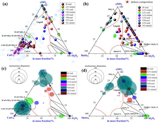
Figure 4.
Composition and size distribution of inclusions during the metallurgical process in CaO-SiO2-Al2O3 and SiO2-MnO-Al2O3 ternary phase diagram at 1873 K. (a) Composition of inclusions in CaO-SiO2-Al2O3 diagram, (b) composition of inclusions in SiO2-MnO-Al2O3 diagram, (c) size distribution of inclusions in CaO-SiO2-Al2O3 diagram, (d) size distribution of inclusions in SiO2-MnO-Al2O3 diagram.
The size of inclusions was represented by the diameter of circles in the diagram as shown in Figure 4c,d, respectively, which were mainly spherical both in the CaO-SiO2-Al2O3 and SiO2-MnO-Al2O3 system. During the latter half of LF1 and the whole LF2 refining process, the sizes of inclusions were up to 30 μm owing to the collision, agglomeration, floatation, and absorption by high basicity slag. Super large-size inclusion up to 100 μm was only observed at the breaking of VD. The rest of the large-size inclusions were mainly located in dual-phase regions, which were around the corner of CaO and SiO2. However, the sizes of inclusions found in the LF3-end and VC-initial were mostly rather smaller compared with VD-end ones. In addition, the sizes of pure liquid inclusions were relatively smaller. The SiO2-MnO-Al2O3 inclusions were firstly observed at the stage of IF-end, then grew up bigger during the stage of the LF refining process. A huge amount of large-sized SiO2-MnO-Al2O3 inclusions that were unabsorbed and undissolved in the refining slag were found after the breaking of VD, which could lead to the failure of flaw detection directly.
The type and the average size of all type inclusions at each stage was shown in Figure 5. The SiO2-MnO-Al2O3 inclusions were found during the whole metallurgical process. The occurrence of Al2O3 and CaO-SiO2-Al2O3 inclusions were presented as complementary. Owing to the incomplete deoxidation in the molten steel and stirring between slag and molten steel during the avoiding of the top slag process, the Al2O3 inclusions were found mostly before the LF2 refining process. Then the Al2O3 inclusions were modified into the MgO-Al2O3 spinel inclusions due to the dissolution of MgO-based refractory. The CaO-SiO2-Al2O3 inclusions remained as the majority till the VC-initial stage. The average size of inclusions at the breaking of VD was much higher than the other stages owing to the appearance of the large amount, large-sized SiO2-MnO-Al2O3 inclusions.
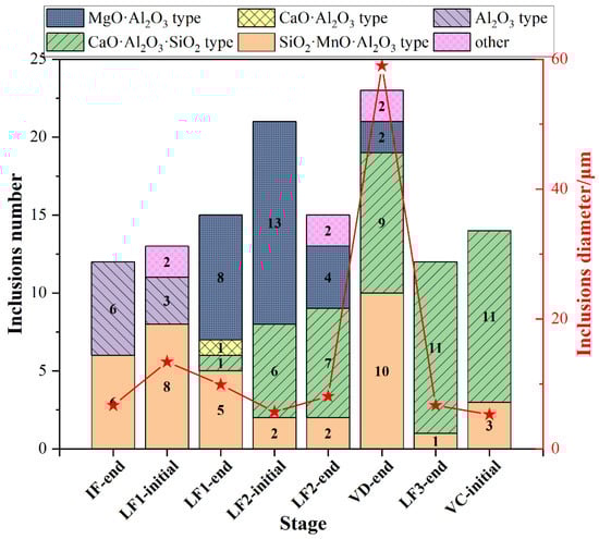
Figure 5.
Type and average size distribution of all inclusions at different stages.
4. Discussion
4.1. Formation Mechanism of the SiO2-MnO-Al2O3 Type Inclusions
Based on observation and analysis for the inclusions found in the metallurgical process, it could be inferred that the SiO2-MnO-Al2O3 inclusions were formed at the end of IF, and remained in the following stages. To clarify the formation mechanism of the SiO2-MnO-Al2O3 inclusion, the stability phase diagrams of the Si-Mn-O system in the Fe-5Cr back-up roller system were calculated through Factsage 8.1 software at different aluminum content (0, 0.003%, 0.007%, 0.01%, 0.015%). The colored dotted line represented different oxygen content in the molten steel, which was shown in Figure 6a–e, respectively. As shown in Figure 6a, at the 0 aluminum content, it could be found that liquid oxide, SiO2, spinel (MnO-Cr2O3), and MnO phases in the molten steel with the content of silicon and manganese ranging from 1 ppm to 10% and 100 ppm to 10%, respectively. Besides, the regions of SiO2, MnO, and liquid oxide phase became larger with the increasing oxygen content in the molten steel, which also indicated that the increasing degree of over-oxidation extended the formation scale of liquid oxide. The spinel and SiO2 phase-field were modified into Al2O3 and mullite phase fields. The Al2O3+liquid oxide dual-phase field was formed in the previous pure liquid oxide phase-field region when the aluminum content increased to 30 ppm. Due to the similar aluminum content, the composition of A3 and A4, A5, and A6 were located in the dual-phase of Al2O3+liquid oxide and marked in Figure 6b,c, respectively. It could be indicated that the endogenous inclusions of each stage should be Al2O3+liquid oxide type, which was verified above. Due to the strong stirring of the VD process and the similar SiO2-MnO-Al2O3 inclusions composition between IF-end and VD-end, as shown in Figure 5b, the SiO2-MnO-Al2O3 inclusions found in the A6(VD-end) could be suggested as the result of slag entrapment containing unabsorbed or undissolved, large-sized SiO2-MnO-Al2O3 inclusions. At a certain oxygen content in the molten steel, the region related to the liquid oxide became smaller with the increasing aluminum content. Consequently, it could be inferred that the aluminum content could promote the decrease of liquid oxide effectively.
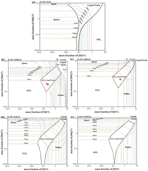
Figure 6.
Calculated oxide stability diagrams of Si-Mn-O system with iso-oxygen contours (in ppm) in Fe-5Cr back-up roller at 1873 K: (a) with 0 Al (b) with 30 ppm Al (c) with 70 ppm Al (d) with 0.01% Al (e) with 0.015% Al.
4.2. Modification of the Liquid Oxide Inclusions
To obtain the quantitative relationship between the aluminum content and the formation of liquid oxide, the evolution of oxide inclusions in Fe-5Cr-0.55C-0.55Si-0.6Mn-6 ppm Ca containing different aluminum contents was calculated with the aid of Factsage 8.1 software, as shown in Figure 7. The FactIPS, FTmisc, and FToxide databases were used for calculation. The soluble oxygen contents in the molten steel ranged from 20 ppm to 200 ppm were shown in Figure 7a,c,e,g, respectively, which corresponded to the different stages in the smelting process. The upper and lower aluminum contents during the smelting process were marked in a blue dotted line. As shown in Figure 7g, at the oxygen content of 200 ppm in molten steel, the SiO2, liquid oxide, and Al2O3 phase existed when the aluminum content was below 100 ppm corresponded to the actual value. The liquid oxide phase disappeared completely, which was replaced by the CA6 (CaO-6Al2O3) phase till the aluminum content reached roughly 0.024%. Besides, the SiO2, Al2O3, and MnO contents in the liquid oxide stayed as the dominating part, and the CaO content in liquid oxide stayed as a minor part. Then, the liquid oxide formed at 200 ppm oxygen content was determined as SiO2-MnO-Al2O3 type inclusions which corresponded to the observed results above. Consequently, it could be inferred that a minimum of 0.024% aluminum content in the molten steel was required to convert the SiO2-MnO-Al2O3 type liquid oxide into the high melting point Al2O3 inclusions, which were widely recognized as easier to remove by their floatation and slag absorption than liquid oxides did [34,35,36,37]. Generally, the contact angles of liquid oxide and solid oxide are below 90° and beyond 90° at 1873 K, respectively, which could reflect the difficulties of slag absorption. The liquid film was formed between the liquid inclusions and slag interface when the liquid inclusions were about to go through the slag-steel interface. Then the slow discharge of liquid film would take rather longer to get absorbed than the solid ones, in which no liquid film has been formed during the process. Then, it could be concluded that reducing of liquid oxide (SiO2-MnO-Al2O3 and CaO-SiO2-Al2O3 type) and modification to the Al2O3 type solid inclusions could promote the cleanness of molten steel effectively. The aluminum content required for the complete modification of solid Al2O3 type inclusions reduced from 0.024% to 0.01% when the oxygen level declined from 200 ppm to 50 ppm, which corresponded to the process of IF melting to LF refining, as shown in Figure 7c,d,e,f. However, in the meanwhile, the CaO content in liquid oxide has risen higher than MnO at the 50 ppm oxygen content in molten steel, which meant the newly formed liquid oxide transformed from SiO2-MnO-Al2O3 type to CaO-SiO2-Al2O3 type corresponding to the analysis in the LF2-refining process. In addition, the newly formed stable phases were converted to CA2 (CaO-2Al2O3) and CA6 (CaO-6Al2O3) phases by the effect of high basicity slag. The required aluminum content for the complete modification rose to 0.02% at the 20 ppm oxygen content in molten steel, which represented the end of the LF refining process in the plant trial. Due to the modification of the high basicity slag and complete oxidation in molten steel, the solid inclusions were converted into pure CA2 inclusion. The content of CaO in liquid oxide has risen higher than SiO2 gradually, as shown in Figure 7a,b. Above all, it could be suggested that a minimum of 0.024% aluminum content could minimize the formation of SiO2-MnO-Al2O3 liquid oxide before the tapping. Besides, maintaining the aluminum content beyond 0.02% in the whole refining process could also minimize the formation of CaO-SiO2-Al2O3 liquid oxide.
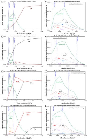
Figure 7.
Equilibrium formation of inclusions during different soluble oxygen content stages at 1873 K in Fe-5Cr-0.55C-0.55Si-0.6Mn-6 ppm Ca-Al in mass % (a,b) with 20 ppm (c,d) with 50 ppm (e,f) with 100 ppm (g,h) with 200 ppm (a,c,e,g) present the formation of all inclusions at different oxygen content (b,d,f,h) present the actual composition of liquid oxide inclusions corresponding to the previous one, respectively.
4.3. Optimization and Verification of Plant Trials
Based on the results and analysis above, the authors brought the aluminum control over the whole smelting process into effect to solve the flaw detection issues caused by SiO2-MnO-Al2O3 type inclusions, as shown in Figure 8. Meanwhile, the composition of slag was redesigned to match both the high aluminum content in molten steel and the refining function. Then, the steel specimens corresponding to the previous stages were also sampled and analyzed as above. Specific details of sampling in the optimized plant trial are shown in Figure 8. The composition of slag specimens in the optimized process is shown in Table 4.
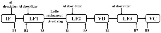
Figure 8.
Schematic illustration of optimized metallurgical process and sampling.
Table 4.
Main chemical composition of slag specimens in the optimization process in mass%.
Morphology and composition of improved typical inclusions at different stages were shown in Table 5. Only aggregating and irregular Al2O3 particles were found before the LF1 refining process. Then, pure Al2O3 particles were modified into small-sized and quasi-spherical CaO-Al2O3 type inclusions in the LF refining process. However, the CaO-Al2O3 type inclusions were modified into CaO-SiO2-Al2O3 type inclusions after the breaking of the VD process. The CaO-SiO2-Al2O3 type inclusions remained as the main inclusions till the casting of the VC process. To illustrate the optimized evolution of large-size inclusions at different stages, the composition and size of inclusions found in specimens B1-B8 were marked in the ternary diagram of the CaO-SiO2-Al2O3 system, as shown in Figure 9. During the whole smelting process, a few inclusions were located at the line of SiO2-Al2O3, which meant few SiO2-MnO-Al2O3 type inclusions were found. Large-sized inclusions were mostly located in the liquid oxide and liquid oxide+CaO dual-phase field, which was relatively smaller than the SiO2-MnO-Al2O3 type ones. Besides, large-sized inclusions were CaO-Al2O3 type at the end of LF2 refining. However, the liquid oxides were mostly converted to CaO-SiO2-Al2O3, which were formed after the breaking of VD. It could be suggested that the inclusions with the tendency of high Al2O3 content usually owned small sizes. On the contrary, the inclusions with the tendency of high CaO content or a certain SiO2 content owned larger sizes generally in this study. Fewer inclusions were found than the original process especially the SiO2-MnO-Al2O3 type, which caused the failure of the MPI test. It showed that the modification of aluminum in the over-oxidation environment before the tapping was effective in a certain degree. In addition, the amount and sizes of inclusions in the optimized process were smaller than the previous ones.
Table 5.
Morphology and composition (in mass %) of typical inclusions at different stages (Specimen B1–B8).
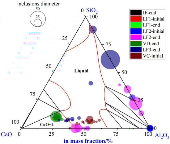
Figure 9.
Composition and size distribution of large-size inclusions during the optimized metallurgical process in CaO-SiO2-Al2O3 ternary phase diagram at 1873 K.
The type and the average size of all type inclusions at each stage was shown in Figure 10. SiO2-MnO-Al2O3 inclusions were found after the LF2-initial stage, which could be entrapped from the slag during the avoiding slag process. Owing to the optimized control of aluminum content, Al2O3 inclusions dominated in inclusions before LF-2 refining, which were modified by the calcium content in the high basicity slag. Besides, the inclusion found at the breaking of VD owned larger sizes than other stages. The appearance of Al2O3 and CaO-SiO2-Al2O3 inclusions was also presented as complementary, which matched the previous results. However, more CaO-SiO2-Al2O3 inclusions were found after the breaking of the VD process than the previous ones. Therefore, the relationship between SiO2, Al2O3 content in the inclusions, and the aluminum content in the molten steel was illustrated and shown in Figure 11. The SiO2 contents in the inclusions and the aluminum content in the molten steel presented a negative correlation. At the end of LF2 refining, the SiO2 contents in the inclusions were almost none. However, the Al2O3 contents of the inclusions decreased rapidly when the smaller SiO2 contents increased. The SiO2 contents decreased gradually after adding in the aluminum wire (aluminum 99%). Consequently, it could be inferred that the aluminum contents in the molten steel could suppress the formation of SiO2 contents in the CaO-SiO2-Al2O3 inclusions to a certain degree. However, the precise inner mechanism requires further investigation [38].
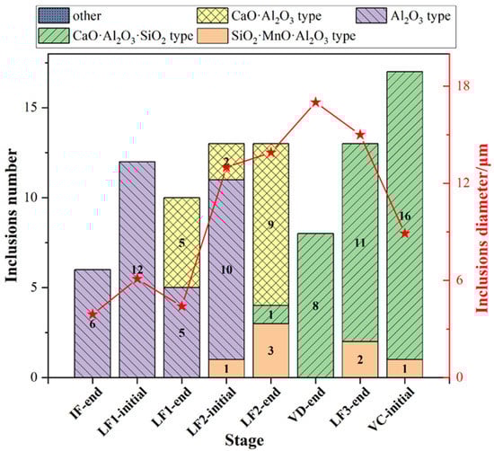
Figure 10.
Type and average size distribution of all inclusions at different stages in the optimized plant trial.
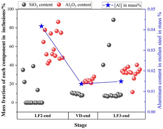
Figure 11.
Mass fraction of SiO2 and Al2O3 contents in the inclusions and the corresponding aluminum content during LF2-end, VD-end, LF3-end stage.
According to the experimental results and thermodynamic calculation, the formation and evolution mechanism of typical inclusions during the original and optimized metallurgical process were illustrated and shown in Figure 12. The scarps and alloys were melted by IF under the atmosphere. Then there would be a huge amount of FeO, MnO, and Cr2O3 oxide formed and entered into the top slag, which provided the oxygen content into the molten steel. If there were insufficient aluminum content in the molten steel, the huge number of SiO2-MnO-Al2O3 inclusions would be formed by the joint control of silicon, manganese, and aluminum over the oxygen content in the molten steel, which was not easy to remove by its floatation and the absorption of the slag. In the refining stage, the CaO content would emerge in both the SiO2-MnO-Al2O3 and Al2O3 inclusions by the modification of the high basicity slag. Besides, the CaO-Al2O3 type inclusions were converted into CaO-SiO2-Al2O3 inclusions owing to the insufficient aluminum content caused the aluminum loss during the VD process and the slag entrapment [39,40,41]. The precise and inner mechanism of these requires further investigation in the next stage.
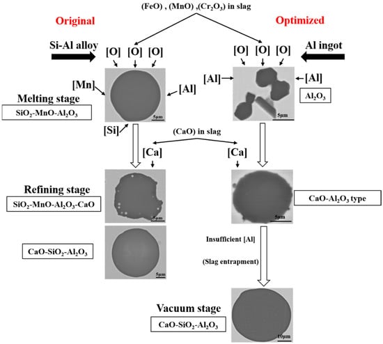
Figure 12.
Schematic of formation and evolution of typical inclusions during the original and optimized metallurgical process.
5. Conclusions
In the current study, the source and formation of the defects that failed in the MPI test in forged backup rollers were investigated and the corresponding optimized process in the plant trials was conducted. Based on the analysis of inclusions characteristics and thermodynamic calculations, the conclusions were obtained as follows:
- (1)
- The linear and aggregating distribution of SiO2-MnO-Al2O3 inclusions up to 3 mm was the cause of the failure in flaw detection. The sizes of SiO2-MnO-Al2O3 were rather uneven. Besides, SiO2-MnO-Al2O3 inclusions with irregular plate strip shapes were uniformly distributed in composition.
- (2)
- SiO2-MnO-Al2O3 type inclusions were mainly formed in the over-oxidation environment during the IF melting. Owing to its low contact angles, large-size SiO2-MnO-Al2O3 inclusions in the defective area were inherited from the initial smelting process. CaO-SiO2-Al2O3 inclusions formed during the LF refining process were the dominating inclusions in the whole process.
- (3)
- The content of aluminum in the molten steel over 0.024% in Fe-5Cr back-up roller steel could suppress the formation of SiO2-MnO-Al2O3 liquid oxide during an over-oxidation environment. CaO-SiO2-Al2O3 liquid oxide inclusions could be completely modified as solid CaO-Al2O3 type inclusions over 0.02% aluminum content during the refining process. After the optimization, the amount and sizes of large-size liquid inclusions (>50 μm) decreased significantly before the VD refining.
Author Contributions
Conceptualization and writing, W.Z.; methodology, W.Z. and Y.Z.; software, W.Z. and G.W.; validation, W.Z., G.W. and Z.Z.; formal analysis, W.Z. and Y.Z.; investigation, W.Z.; supervision, Y.Z. and G.C.; project administration, Y.Z. and G.C. All authors have read and agreed to the published version of the manuscript.
Funding
This research was funded by the National Natural Science Foundation of China, grant numbers U196021 and 51874034.
Institutional Review Board Statement
Not applicable.
Informed Consent Statement
Not applicable.
Data Availability Statement
Not applicable.
Acknowledgments
The authors would like to express appreciation to the National Natural Science Foundation of China for the financial support, the State Key Laboratory of Advanced Metallurgy at the University of Science and Technology Beijing, and to Luoyang CITIC HIC Casting and Forging Co., Ltd., for academic and experimental assistance.
Conflicts of Interest
The authors declare no conflict of interest.
References
- Yu, S.D.; Chen, H. Current Status and Several Problems of Roller Industry in China. Iron Steel 2007, 42, 1–6. [Google Scholar]
- Montmitonnet, P.; Buessler, P. A Review on Theoretical Analyses of Rolling in Europe. ISIJ Int. 1991, 31, 525–538. [Google Scholar] [CrossRef][Green Version]
- Gonzalez, W.B.; Llano, J.; García, J. Metallurgical Application to Work and Back Up Rolls for Hot & Cold Rolling of Flat Products; Rolls for Flat Rolling of Steel: Lugones, Spain, 2007. [Google Scholar]
- Mammeri, A.; Belzune, F.J.; Rodirguez, C.; Torre, M.; Poveda, S.; Garcia, J. Mechanical Properties of Chromium Steels for Back up Rolling Rolls. Rev. Metal. 2003, 39, 107–113. [Google Scholar] [CrossRef][Green Version]
- Nakagawa, Y.; Hashimoto, T.; Katayama, H.; Morikawa, H. Development of High-Cr Roll for Hot Strip Mill with Superior Resistance to Surface Deterioration and Spalling of Outer Shell. Tetsu-to-Hagane 1988, 74, 1993–2000. [Google Scholar] [CrossRef]
- Shimizu, M.; Shitamura, O.; Matsuo, S.; Kamata, T.; Kondo, Y. Development of High Performance New Composite Roll. ISIJ Int. 1992, 32, 1244–1249. [Google Scholar] [CrossRef]
- Di Schino, A.; Di Nunzio, P.E. Metallurgical Aspects Related to Contact Fatigue Phenomena in Steels for Back-Up Rolls. Acta Metall. Slovaca 2017, 23, 62–71. [Google Scholar] [CrossRef]
- Jia, R.; Li, X.D.; Li, J.C.; Gu, K. Present Research Situation on Cr5 Series Large Back-up Roll Process in China. Hot Work. Technol. 2013, 42, 62–65. [Google Scholar]
- Mccann, J. Overview of Work Rolls for Cold Rolling. Ironmak. Steelmak. 2000, 27, 15–18. [Google Scholar]
- Kang, X.; Li, D.; Xia, L.; Campbell, J.; Li, Y. Development of Cast Steel Back-up Roll. Int. J. Cast Met. Res. 2006, 19, 66–71. [Google Scholar] [CrossRef]
- Ichino, K.; Ishikawa, S.; Kataoka, Y.; Toyooka, T. Improvement of Hot Wear Characteristic of High Speed Tool Steel Roll by Increase in Cr and Mo Contents. Tetsu-to-Hagane 2003, 89, 680–685. [Google Scholar] [CrossRef][Green Version]
- Yu, H.; Ji, C.; Chen, B.; Wang, C.; Zhang, Y. Characteristics and Evolution of Inclusion Induced Surface Defects of Cold Rolled IF Sheet. J. Iron Steel Res. Int. 2015, 22, 17–23. [Google Scholar] [CrossRef]
- Sano, Y.; Hattori, T.; Haga, M. Characteristics of High-Carbon High Speed Steel Rolls for Hot Strip Mill. ISIJ Int. 1992, 32, 1194–1201. [Google Scholar] [CrossRef]
- Kobayashi, K. Technical View on Forged Steel Rolls in Japan. Tetsu-to-Hagane 1971, 57, 725–737. [Google Scholar] [CrossRef][Green Version]
- Chen, J.L. Development of Cr5 Forged Blank of Cold-Rollers. Forg. Stamp. Technol. 2006, 31, 10–12. [Google Scholar]
- Zhou, Q.; Zhang, J.; Yin, Y.; Zhai, M. Characterization of Inclusions in Axle Steel by Ingot Casting. Metall. Res. Technol. 2019, 116, 501–508. [Google Scholar] [CrossRef]
- Huang, H.G.; Du, F.S.; Zhang, F. FEM Analyses on Forming Mechanics of Inclusion Defects Inner Heavy Backup-Roll Forging. China Mech. Eng. 2009, 20, 477–481. [Google Scholar]
- Dong, B.L. Cause Analysis on Exposed Inclusion and Steel Melting Process Optimization of Backup Roll. Heavy Cast. Forg. 2019, 40, 46–48. [Google Scholar]
- Gotoh, K.; Okada, H.; Sasaki, T.; Koide, T. Effects of Roll Surface Deteriorations on Scale Defect in Hot Rolling. Tetsu-to-Hagane 1998, 84, 861–867. [Google Scholar] [CrossRef][Green Version]
- Takechi, H.; Namba, K.; Kawasaki, K.; Fujiwara, K. Evaluation of the Fatigue Damage of Rolls for Strip Mills below the Surface by X-ray Diffraction Method. Tetsu-to-Hagane 1979, 65, 2067–2075. [Google Scholar] [CrossRef]
- Ray, A.K.; Mishra, K.K.; Chaudhary, P.N. Failure Analysis of Rolls of Cold Rolling Mill in Steel Plant. In Failure Analysis, Proceedings of the Clinic on Failure Analysis, Jamshedpur, India, 18–19 February 1997; NML: Jamshedpur, India, 1997; pp. 37–46. [Google Scholar]
- Wang, R.; Bao, Y.; Li, Y.; Yan, Z.; Li, D.; Kang, Y. Influence of Metallurgical Processing Parameters on Defects in Cold-Rolled Steel Sheet Caused by Inclusions. Int. J. Miner. Metall. Mater. 2019, 26, 440–446. [Google Scholar] [CrossRef]
- Wang, Q.; Li, Z.; Shi, Y.; Wang, L.; Liu, F. Interior Crack and Its Formation Mechanism in Overlaying Weld of Back-up Rolls. Eng. Fail. Anal. 2013, 34, 268–277. [Google Scholar] [CrossRef]
- Jamil, M.; Khan, A.M.; Hegab, H.; Sarfraz, S.; Sharma, N.; Mia, M.; Gupta, M.K.; Zhao, G.; Moustabchir, H.; Pruncu, C.I. Internal Cracks and Non-Metallic Inclusions as Root Causes of Casting Failure in Sugar Mill Roller Shafts. Materials 2019, 12, 2474. [Google Scholar] [CrossRef] [PubMed]
- Lu, J.; Cheng, G.; Wu, M.; Yang, G.; Che, J. Detection and Analysis of Magnetic Particle Testing Defects on Heavy Truck Crankshaft Manufactured by Microalloyed Medium-Carbon Forging Steel. J. Iron Steel Res. Int. 2020, 27, 608–616. [Google Scholar] [CrossRef]
- Wang, Q.; Cheng, G.; Li, J.; Dou, W.; Hu, X. Formation Mechanism of Large Inclusions in 80t 20Cr–8Ni Stainless Steel Casting for Nuclear Power. Steel Res. Int. 2019, 90, 1900349. [Google Scholar] [CrossRef]
- Goto, K.; Matsuda, Y.; Sakamoto, K.; Sugimoto, Y. Basic Characteristics and Microstructure of High-Carbon High Speed Steel Rolls for Hot Rolling Mill. ISIJ Int. 1992, 32, 1184–1189. [Google Scholar] [CrossRef]
- Lee, W.-H.; Liu, Y. Laboratory Evaluation of New Type of Backup Roll for Strip Shape Control. ISIJ Int. 2005, 45, 1636–1640. [Google Scholar] [CrossRef]
- Prasad, M.S.; Ray, A.; Dhua, S.K.; Avtar, R.; Jha, S. Premature Failure of Work-Rolls in Tandem Mill: Some Microstructural Revelations. J. Fail. Anal. Prev. 2004, 4, 67–72. [Google Scholar] [CrossRef]
- Kimura, T.; Ishii, M.; Amano, K.; Ueda, S.; Oka, Y.; Nakano, S. Secondary Hardening Characteristics and Those Effects on the Wear and Thermal Shock Resistance of 5%Cr-Mo-V Steel Roll for Cold Strip Mill. ISIJ Int. 1992, 32, 1224–1231. [Google Scholar] [CrossRef][Green Version]
- Parry, G.; Ostrovski, O. Wetting of Solid Iron, Nickel and Platinum by Liquid MnO–SiO2 and CaO–Al2O3–SiO2. ISIJ Int. 2009, 49, 788–795. [Google Scholar] [CrossRef]
- Vantilt, S.; Coletti, B.; Blanpain, B.; Fransaer, J.; Wollants, P.; Sridhar, S. Observation of Inclusions in Manganese-Silicon Killed Steels at Steel-Gas and Steel-Slag Interfaces. ISIJ Int. 2004, 44, 1–10. [Google Scholar] [CrossRef]
- Wang, K.; Jiang, M.; Wang, X.; Wang, Y.; Zhao, H.; Cao, Z. Formation Mechanism of SiO2-Type Inclusions in Si-Mn-Killed Steel Wires Containing Limited Aluminum Content. Metall. Mater. Trans. B 2015, 46, 2198–2207. [Google Scholar] [CrossRef]
- Shinozaki, N.; Echida, N.; Mukai, K.; Takahashi, Y.; Tanaka, Y. Wettability of Al2O3-MgO, ZrO2-CaO, Al2O3-CaO Substrates with Molten Iron. Tetsu-to-Hagane 1994, 80, 748–753. [Google Scholar] [CrossRef]
- Van Ende, M.-A.; Guo, M.; Proost, J.; Blanpain, B.; Wollants, P. Formation and Morphology of Al2O3 Inclusions at the Onset of Liquid Fe Deoxidation by Al Addition. ISIJ Int. 2011, 51, 27–34. [Google Scholar] [CrossRef]
- Kapilashrami, E.; Sahajwalla, V.; Seetharaman, S. Investigation of the Wetting Characteristics of Liquid Iron on Mullite by Sessile Drop Technique. ISIJ Int. 2004, 44, 653–659. [Google Scholar] [CrossRef]
- O’Malley, R.J. Inclusion Evolution and Removal in Ladle Refining; Missouri University of Science & Technology: Rolla, MO, USA, 2017. [Google Scholar]
- Wu, S.; Guo, X.; Wang, Y.; Wu, G.; Lyu, S. Laboratory Study on Evolution Mechanism of Nonmetallic Inclusions in Al-Deoxidized Spring Steel. Trans. Indian Inst. Met. 2020, 73, 2807–2816. [Google Scholar] [CrossRef]
- Kawakami, K.; Taniguchi, T.; Nakashima, K. Generation Mechanisms of Non-Metallic Inclusions in High-Cleanliness Steel. Tetsu-to-Hagane 2007, 93, 743–752. [Google Scholar] [CrossRef]
- Deng, Z.; Zhu, M. Deoxidation Mechanism of Al-Killed Steel during Industrial Refining Process. ISIJ Int. 2014, 54, 1498–1506. [Google Scholar] [CrossRef]
- Miao, Z.; Cheng, G.; Li, S.; Qiu, W.; Zeng, L.; Long, H. Formation Mechanism of Large-Size CaO–Al2O3–MgO–SiO2 Inclusions in High Carbon Chromium Bearing Steel. ISIJ Int. 2021, 61, 2083–2091. [Google Scholar] [CrossRef]


Publisher’s Note: MDPI stays neutral with regard to jurisdictional claims in published maps and institutional affiliations. |
© 2022 by the authors. Licensee MDPI, Basel, Switzerland. This article is an open access article distributed under the terms and conditions of the Creative Commons Attribution (CC BY) license (https://creativecommons.org/licenses/by/4.0/).