Article

Microstructure and Properties of Press-Bonded Dissimilar Stainless Steel and Mild Carbon Steel Ingots

School of Mechanical Engineering and Automation, Northeastern University, Shenyang 110819, China
*
Author to whom correspondence should be addressed.
Metals 2022, 12(12), 2142; https://doi.org/10.3390/met12122142
Submission received: 16 November 2022 / Revised: 4 December 2022 / Accepted: 12 December 2022 / Published: 14 December 2022
(This article belongs to the Special Issue Advanced Technology in Microalloyed Steels)

Abstract

:
Dissimilar steel welds between stainless and mild steels are necessary for the efficient utilization of stainless steels in construction. In the present work, a dissimilar large-sized steel ingot was fabricated by press bonding a Q235 steel to a SUS 304 steel at 1100–500 °C. The microstructure of bonded interfaces has been characterized by scanning electron microscopy, electron probe microanalysis, and transmission electron microscopy, together with tensile tests to evaluate the bonding strength. It has been demonstrated that a strong-bonded, high-quality, dissimilar steel ingot could be fabricated by press bonding. The (Fe, Cr)3C carbide is present in the narrow zone of diffusion-bonded stainless steel and mild steel. Interestingly, the maximum hardness is not too high to make the transition zone brittle but enough to constrain the narrow soft ferrite during tensile and fatigue tests, causing the final fracture to occur in the mild steel region rather than the bonding interface.

1. Introduction

Traditionally, stainless steel has been considered an extravagant solution to structural engineering problems due to the relatively high material cost. However, the emergence of structural stainless steel design codes and a better understanding of the unique benefits of stainless steel properties are bringing more interest to the application of conventional structural engineering materials. In terms of the efficient utilization of stainless steels for civil structural engineering, it is necessary to use dissimilar steel welds between stainless and mild steels because mild steel is commercially available while maintaining the special properties of stainless steels.
Large steel ingots are of paramount importance in the energy, chemical, and mechanical industries. Large steel ingots are difficult to fabricate, even by electroslag remelting processes [1], due to macrosegregation. Diffusion bonding [2] and deformation bonding [3] are competent methods for joining similar and dissimilar materials. Diffusion bonding of materials in a solid state is a process for making a monolithic joint through the formation of bonds at the atomic level as a result of the closure of the mating surfaces due to local plastic deformation at elevated temperature, which aids interdiffusion at the surface layers of the materials being joined [2]. In deformation bonding, layers of the component materials are stacked and subjected to large plastic deformation until they are bonded together; this is the most efficient technique from the industrial processing viewpoint and includes pressing, rolling, and explosive bonding [3]. Press and roll bonding have been used to fabricate laminated metal composites [4,5,6,7,8]. To make a large steel ingot, several high-quality round ingots are stacked and subjected to large plastic deformation, so press bonding is the most suitable technique. Lee et al. [9] fabricated heavy titanium parts with massive diffusion bonding of multi-sheets by applying a low pressure of inert gas. Sun et al. [10] reported the leading manufacture of the first large-scale integral weldless stainless steel forging ring by multilayer additive hot-compression bonding technology. Liu et al. [11] manufactured a large high-speed homogeneous steel consisting of four blocks using the optimal processing parameters (1150 °C/50% strain), obtained by hot-compression bonding tests in a Gleeble 3500 machine. Xie et al. [12] fabricated a heavy plate with excellent mechanical properties using the multilayer hot-compression bonding method, based on the optimal deformation and holding conditions for interface bonding. However, little work is available in the literature about large, dissimilar ingots.
In order to fabricate dissimilar steel ingots, ingots of similar metals, such as carbon steel, stainless steel, and copper, have been successfully fabricated by hot-press bonding several ingots into one monolithic larger ingot. This study focuses on the microstructure and mechanical properties, especially the tensile and high cycle fatigue properties, of a dissimilar ingot press-bonded from a mild carbon steel Q235 into an austenitic stainless steel SUS340.

2. Materials and Methods

Table 1 shows the analyzed chemical compositions of mild carbon steel Q235 and austenitic stain-free steel SUS 304. Two cylinder ingots (⌀ 280 mm × 100 mm) were cut, fine machined, cleaned with acetone, and assembled end to end by a tight weld, as shown in Figure 1a. A small stainless steel tube was tight welded after the assembly was evacuated to a pressure of 0.5 Pa for 30 min. The assembled ingot was heated at 1100 °C for 1 h in a resistance heating furnace, pressed at a rate of 2 mm/s for about 20 s using a 50 MN hydraulic press, the pressure increased from 15 MPa to 20 MPa, and kept constant at 20 MPa until the sample cooled (insulated by a thermal barrier between anvils and the sample) to about 500 °C (using a UT303D+ infrared thermodetector) in 20 min, the sample was unloaded to cool within a thermal barrier in air to room temperature. The height of the samples decreased from 200 to 160 mm, the corresponding true strain was 0.22, and the average strain rate was 0.01/s.
The bonded ingot was machined, as shown in Figure 1b, and cut into various samples using an electro-discharge machine for mechanical property testing and microstructure observation. In order to observe the microstructure of the bonding interface, the samples were ground and polished to 1 μm diamond paste, the mild carbon was etched using nital reagent, and the SUS 304 stainless steel was etched using aqua regia nitrohydrochloric acid. Metallographic observations were performed utilizing an OLYMPUS-DSX-500 optical microscope and an OXFORD-7582 scanning electron microscope (SEM) with an electron backscattering diffractometer (EBSD Oxford) detector. The interface compositions were determined using energy dispersive spectrometry (EDS) in the SEM. The EBSD specimens were mechanically polished, followed by argon ion polishing for 1 h. The accelerating voltage for the EBSD examination was 20 kV, and the step size was 50 nm. Data acquisition and post-processing were performed using the HKL Channel 5 software. The fine microstructure at the interface was examined using a JEOL JEM 2100F transmission electron microscopy (TEM) operated at 200 kV. Thin TEM foils were ground to 50 μm and twinjet polished in a 5% perchloric acid solution at −20 °C with a voltage of 20 V. The room temperature tensile properties, Charpy U-notched energy, microhardness and nanoindentation hardness, and high-cycle fatigue were evaluated. Samples for the tensile and fatigue tests were ground on abrasive paper. Uniaxial tensile testing was performed at room temperature using a SANSCMT-5000 universal testing machine. A constant strain rate of 5 × 10⁻³ s−1 was employed for this study. Microhardness testing was performed using the FEM-700 microhardness tester under a load of 9.8 N in 10 s. Nanoindentation was conducted on a G200 nanoindenter at 10 nm/s to 1000 nm depth. High-cycle fatigue testing was carried out on a QBG-100 high-frequency fatigue machine under alternative tensile and compression stresses with a resonance frequency of 100–130 Hz.

3. Results and Discussion
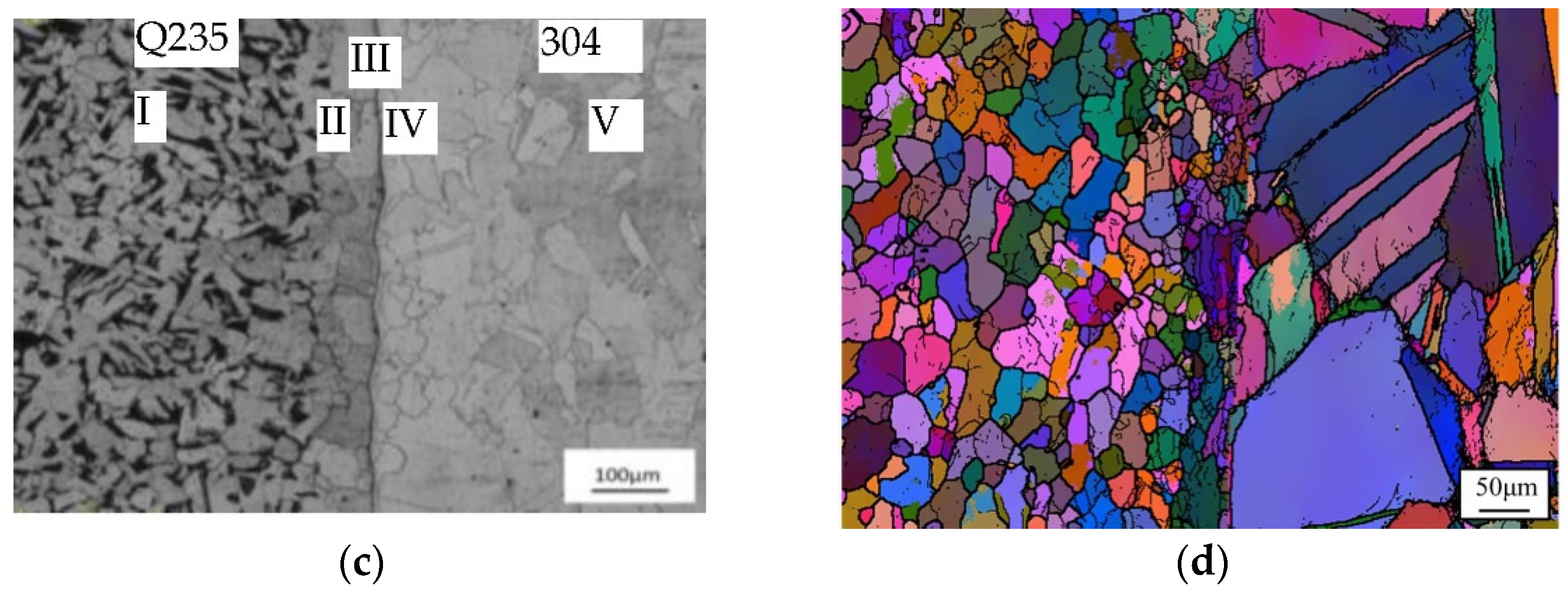
3.1. Microstructure

The initial microstructures of Q235 and 304 before bonding (BD) are shown in Figure 2a,b. The optical and SEM examinations performed on the interface and materials as bonded are shown in Figure 2c,d. The interface exhibits good bonding and is free from voids and oxides, although Xie et al. [13] reported that thick oxide scale was formed in low vacuum and remained at the bonding interface between 316 LN after hot-compression bonding at 1200 °C. As shown in Figure 2c, five distinct zones are observed, corresponding to: (I) parent Q235 with typical ferrite (white) and pearlite (black) microstructure, as that of Q235 before bonding; (II) fine grain ferrite stabilized zone of 2–4 grain width near the bonding interface; pearlite grains disappear in this zone; (III) transition zone; (IV) fine grain austenite zone; and (V) coarse grain austenite grain zone. The microstructures of zones I–II are in good agreement with the literature [14,15,16,17,18]. The EBSD map on the interface is shown in Figure 2d. Stainless steel SUS304 has coarse polyhedral austenite grains, while mild carbon steel Q235 maintains equiaxed grains, in which a number of fine grains of various orientations are distributed along the bonding interface, more on the side of Q235 steel. These fine grains are presumably brought about partly by dynamical recrystallization due to a larger strain at the interface.
The scanning electron micrographs of the joint interface are shown in Figure 3a,b. A distinct ferrite-stabilized zone (II) of about 100 μm width near the perfect interface is shown in Figure 3a. Figure 3b shows the deep etched interface microstructure; there is a transition zone (III) of 1 μm width along the interface; acicular carbides are present in this zone, as shown in the enlarged image in the lower right corner and on the austenite grain boundaries indicated by arrows in Figure 3b. The transition zone is composed of acicular carbide and ferrite. Vigraman et al. [18] called the transition zone the reaction zone, while Kurt et al. [14] called it the Cr-carbide region.
The compositions across the bonding interface were evaluated by energy dispersive spectroscopy (EDS). The line scanning of element Cr across the interface is shown in Figure 4a, and local Cr distribution across the interface in a region of 15 μm is shown in Figure 4b. The average concentration of Cr by EDS (spot analyses) in the middle of the transition zone is about 9%, half of that in stainless steel. The average concentration of Cr in ferrite stabilized zone decreases from 3.5 to 0.7% in an interval of 2–5 μm away from the transition zone. Cr atoms diffuse from the stainless steel across the bonding interface to carbon steel, while Fe and carbon atoms diffuse from carbon steel to the stainless steel. The width of the diffusion zone of Cr in the austenitic steel is about 3 μm; that in the carbon steel is larger than 3 μm. The main reason for the difference in diffusion zone between both sides is that the diffusion coefficients of Cr in gamma iron are greater than that of alpha iron [19]. Stanley [20] reported that at 725 °C, the diffusion of C atoms in alpha iron is over 100 times as fast as it is in gamma iron. Thus, C atoms partly diffuse from the carbon steel into the austenite across the interface and dissolve in it. Since austenite has high carbon solubility, some of the carbon atoms diffuse into stainless steel far away from the interface along the high angle boundaries. Diffusion along grain boundaries is greater than volume diffusion and reaches a maximum around 45° for high-angle (θ > 20°) grain boundaries [21]. Bokshtein et al. [22] demonstrated preferential diffusion of carbon along grain boundaries of a Fe-14.3%Cr alloy at 500–700 °C and 950 °C, where there was a marked enrichment of the grain boundaries with carbon and a diffusion of carbon from the boundaries into the grain. In this study, atoms from carbon steel Q235 diffuse across the interface, partly into the austenite grain and partly along the high-angle boundaries far into the stainless steel. Upon cooling, carbon and chromium atoms interact with each other to form carbides in the transition zone and austenite grain boundaries and further restrict the movement of grain boundaries, finally resulting in the presence of fine austenite grains on the side of stainless steel at the interface. Meanwhile, the ferrite stabilizer chromium from stainless steel dissolves in the carbon steel depleted of carbon, leading to the formation of the ferrite stabilized zone upon cooling.
TEM examination also shows that there is a transition zone across the interface, as shown in Figure 5, where carbides (black) are distributed in the ferrite matrix, causing the formation of pearlite. Selected area electron diffraction at the areas denoted by A, B, and C reveals that the carbides in the transition zone denoted by B are alloy carbides of (Fe, Cr)3C. Kurt et al. [14,15,16] reported that carbide Cr23C6 is present in the carbide zone of diffusion-bonded stainless steel and medium carbon couples. Vigraman et al. [18] considered the carbides as FeC and CrC. The present results are in good agreement with the studies reported by Kurt et al. and Vigraman et al.

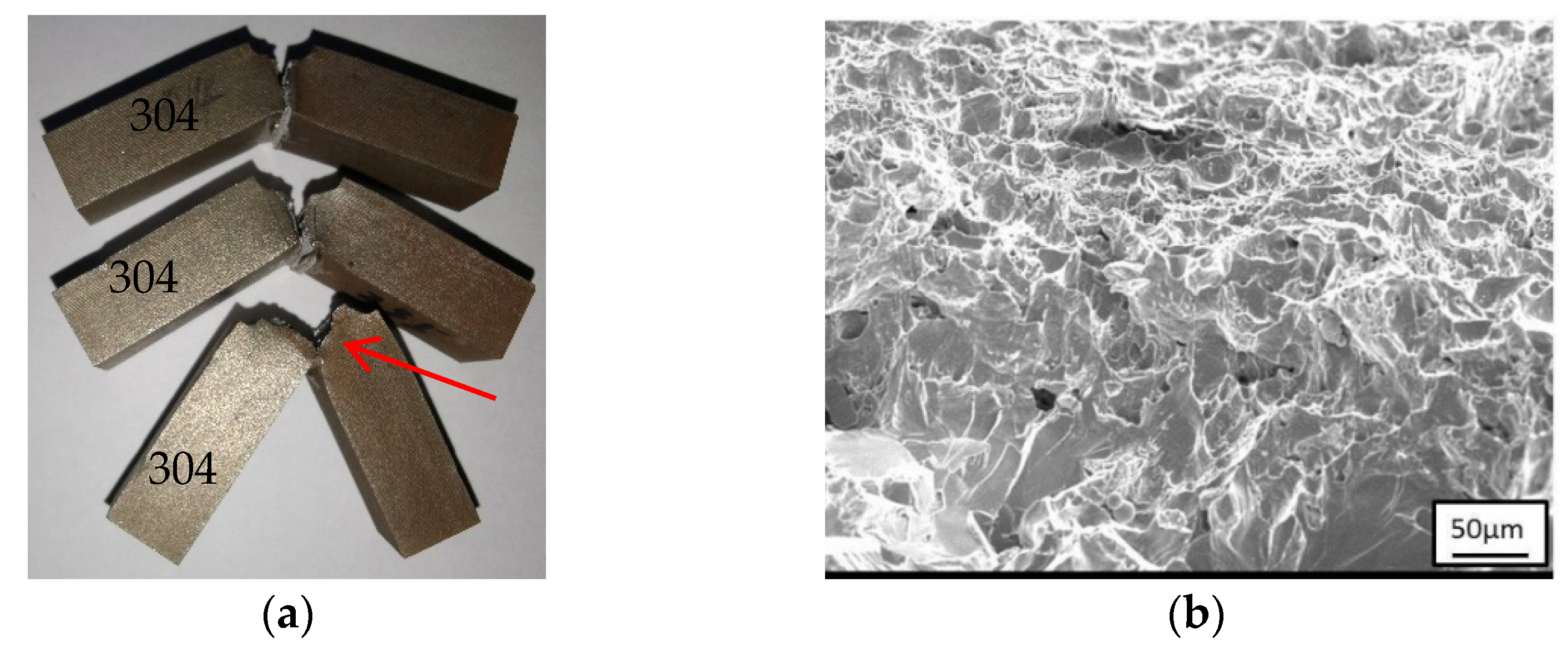
3.2. Mechanical Properties

To evaluate the overall properties of the Q235 and 304 joints, a series of tensile tests, Charpy impact tests, and high-cycle fatigue tests are performed. Table 2 shows the tensile properties, Charpy U-notch energy, and high cycle fatigue strengths obtained. Note that the corresponding properties of initial Q235 and 304 plates before bonding (BD) are also shown in the comparisons.
From Table 2, it is clear that the average yield and ultimate tensile strengths of a bonded joint are 236 MPa and 430 MPa, respectively, which are almost the same as those of Q235 steel before bonding. The typical tensile engineering stress—engineering strain curves of a press-bonded joint, Q235 and 304 before bonding (BD) and as bonded, are shown in Figure 6. All three samples of bonded joints fractured in Q235 are about 8 mm away from the interface (as shown in the bottom-right corner of Figure 6a, showing a typical cup and cone fracture with ductile dimples, as shown in Figure 6b). The total elongation of the bonded joint is almost half that of Q235 because the plastic deformation of the samples was mainly contributed by Q235 and the yielding point phenomenon of mild steels is inhibited. All samples did not fracture along the bonding interface, which indicates that the tensile strength of the joint is greater than that of Q235 and the bonded joint is strong.
The average Charpy U-notch energy of a bonding joint is 118 J, which is slightly larger than that of the Q235 side but smaller than that of the initial Q235 mild steel before bonding. The macrographs and morphologies of the impact samples of the bonded Q235/304 joint are shown in Figure 7. The cracks have been found to initiate in the middle of the U-notch and then propagate along the interface to the Q235 side, as shown by the red arrow. The SEM fractograph shows a mixed mode of ductile and quasi-cleavage fracture, which is characterized by some dimples and a river pattern, respectively. It is worth noting that all Charpy U-notched impact samples fractured at the side of Q235 rather than at the bonded joint, implying that the present Q235/304 bonded joint exhibits higher fracture toughness than Q235 mild steel.
Figure 8 shows the S-N curve and three typical fatigue fractured samples, and the fatigue endurance of 170 MPa was used in this study. Surprisingly, all tested fatigue samples fractured in the parent zone of Q235 mild steel, not in the ferrite-stabilized zone or the bonding interface transition zone. This phenomenon demonstrates that the Q235/304 bonded joint exhibits higher fatigue properties than Q235 mild steel. Figure 8b shows the corresponding SEM fractograph of the fatigue sample after 2.1 × 10⁵ cycles at 200 MPa, which shows a transgranular-type brittle fracture with a large number of cleavage planes and river patterns. Similarly, the results of the fatigue properties demonstrate that the present press-bonded Q235/304 joint is strong enough to avoid the fracture occurring at the interface under high cycle fatigue conditions.
Microhardness testing shows that there is a maximum hardness zone and a minimum hardness zone across the bonding interface, which correspond to the transition zone and the ferrite stabilized zone, as discussed above. The values of microhardness tend to increase from the bonding interface to the Q235 side to some extent, and the maximal value of hardness is reached in the transition zone, as shown in Figure 9a. Nanoindentation using a much smaller indenter tip and loader is a more accurate test method to analyze the hardness distribution, especially in a narrow zone. Figure 9b shows micrographs of four partial indent lines across the interface and the average hardness distribution across the interface in an interval of 320 μm. The values of hardness tend to decrease from the bonding interface to the Q235 side, which is consistent with the gradient Cr solution strengthening and the plasticity constraints of the harder transition zone [23,24]. The maximum hardness is not too high to make the transition zone brittle, but it is sufficient to constrain the narrow soft ferrite-stabilized zone during tensile and fatigue tests to assume large plastic deformation.
According to the results, it can be inferred that all properties of the Q235 mild steel and 304 stainless steel joints, including tensile strengths, Charpy U-notched energy, microhardness, nanoindentation hardness, and high cycle fatigue strength, are dependent on that of Q235 mild steel, demonstrating that the current bonded joint of Q235/304 is strong enough and, at the very least, stronger than Q235 mild steel.

4. Conclusions

The microstructure and properties of a dissimilar ingot fabricated by diffusion bonding mild carbon steel into austenitic stainless steel were investigated. The following results were obtained:
  • A strong, high-quality, dissimilar steel ingot of mild carbon steel and austenitic stainless steel can be fabricated by press bonding;
  • There is a soft ferrite stabilized zone and a hard carbide transition zone along the bonding interface;
  • The mechanical properties are dependent on those of the mild carbon steel and not on the bonding interface; the carbides do not impair the mechanical properties.

Author Contributions

Conceptualization, X.H. and Z.L.; methodology, X.H.; software, Z.L.; validation, X.H. and Z.L.; data curation, X.H.; writing—original draft preparation, Z.L.; writing—review and editing, X.H.; All authors have read and agreed to the published version of the manuscript.

Funding

This research received no external funding.

Institutional Review Board Statement

Not applicable.

Informed Consent Statement

Not applicable.

Data Availability Statement

Not applicable.

Conflicts of Interest

No conflict of interest was declared in this work.

References

  1. Medovar, B.I.; Boyko, G.A. Electroslag Technology; Springer Inc.: New York, NY, USA, 1991; pp. 184–189. [Google Scholar]
  2. Kazakov, N.F. Diffusion Bonding of Materials; Mir Publishers: Moscow, Russia, 1985; pp. 10–12. [Google Scholar]
  3. Lesuer, D.R.; Syn, C.K.; Sherby, O.D.; Wadsworth, J. Mechanical behaviour of laminated metal composites. Int. Mater. Rev. 1996, 41, 169–197. [Google Scholar] [CrossRef]
  4. Sherby, O.D.; Wadsworth, J.; Caligiuri, R.D.; Eiselstein, L.E.; Snyder, B.C.; Whalen, R.T. Superplastic bonding of ferrous laminates. Scr. Metall. 1979, 13, 941–946. [Google Scholar] [CrossRef]
  5. Li, S.; Zhang, Q.D. Coupled deformation and diffusion process at the stainless steel/carbon steel interface in the deformation bonding process. Strength Mater. 2018, 50, 818–823. [Google Scholar] [CrossRef]
  6. Li, H.; Yang, C.; Sun, L.X.; Li, M.Q. Hot press bonding of γ-TiAl and TC17 at a low bonding temperature by imposing plastic deformation and post heating. Mater. Lett. 2017, 187, 4–6. [Google Scholar] [CrossRef]
  7. Huschka, M. Press cycle for multilayer bonding. Circuit World 1990, 16, 40–45. [Google Scholar] [CrossRef]
  8. Amirkhanlou, S.; Ketabchi, M.; Parvin, N.; Khors, S.; Bahrami, R. Accumulative press bonding: A novel manufacturing process of nanostructured metal matrix composites. Mater. Des. 2013, 51, 367–374. [Google Scholar] [CrossRef]
  9. Lee, H.; Yoon, B.; Yi, Y. Fabrication of titanium parts by massive diffusion bonding. J. Mater. Process. Technol. 2008, 201, 280–284. [Google Scholar] [CrossRef]
  10. Sun, M.; Xu, B.; Xie, B.; Li, D.; Li, Y. Leading manufacture of the large-scale weldless stainless steel forging ring: Innovative approach by the multilayer hot-compression bonding technology. J. Mater. Sci. Technol. 2021, 71, 84–86. [Google Scholar] [CrossRef]
  11. Liu, W.; Zhang, J.; Sun, M.; Xu, B.; Cao, Y.; Li, D. A hot compression bonding method for manufacturing large high-speed homogeneous steels. J. Mater. Res. Technol. 2022, 17, 507–522. [Google Scholar] [CrossRef]
  12. Xie, B.; Sun, M.; Xu, B.; Wang, C.; Zhang, J.; Zhao, L.; Li, D.; Li, Y. Evolution of interfacial characteristics and mechanical properties for 316LN stainless steel joints manufactured by hot-compression bonding. J. Mater. Process. Technol. 2020, 283, 116733. [Google Scholar] [CrossRef]
  13. Xie, B.; Sun, M.; Xu, B.; Wang, C.; Jiang, H.; Li, D.; Li, Y. Oxidation of stainless steel in vacuum and evolution of surface oxide scales during hot-compression bonding. Corros. Sci. 2019, 147, 41–52. [Google Scholar] [CrossRef]
  14. Kurt, B.; Çalik, A. Interface structure of diffusion bonded duplex stainless steel and medium carbon steel couple. Mater. Charact. 2009, 60, 1035–1040. [Google Scholar] [CrossRef]
  15. Kurt, B.; Orhan, N.; Ozel, S. Interface microstructure of diffusion bonded austenitic stainless steel and medium carbon steel couple. Sci. Technol. Weld. Join. 2007, 12, 197–201. [Google Scholar] [CrossRef]
  16. Kurt, B. The interface morphology of diffusion bonded dissimilar stainless steel and medium carbon steel couples. J. Mater. Process. Technol. 2007, 190, 138–141. [Google Scholar] [CrossRef]
  17. Kurt, B.; Eroglu, M. Diffusion bonding between high chromium white iron and austenitic stainless steel. Sci. Technol. Weld. Join. 2007, 12, 467–471. [Google Scholar] [CrossRef]
  18. Vigraman, T.; Narayanasamy, R.; Ravindran, D. Microstructure and mechanical property evaluation of diffusion-bonded joints made between SAE 2205 steel and AISI 1035 steel. Mater. Des. 2012, 35, 156–169. [Google Scholar] [CrossRef]
  19. Davies, G.A.; Ponter, A.B.; Menzies, I.A. The diffusion of chromium in iron and low carbon steels. Acta Metall. 1967, 15, 1799–1804. [Google Scholar] [CrossRef]
  20. Stanley, J.K. The diffusion and solubility of carbon in alpha. Met. Trans. 1949, 185, 725–761. [Google Scholar] [CrossRef]
  21. Achter, M.R.; Smoluchowski, R. Diffusion in grain boundaries and their structures. J. Appl. Phys. 1951, 22, 1260–1264. [Google Scholar] [CrossRef]
  22. Bokshtein, S.Z.; Gubareva, M.A.; Kontorovich, I.E.; Moroz, L.M. Peculiarities of the diffusion of carbon in iron. Met. Sci. Heat Treat. 1961, 3, 6–9. [Google Scholar] [CrossRef]
  23. Kelly, P.; Hills, D.A.; Nowell, D. Models for plastic constraint in brazed or diffusion-bonded joints between ceramic components. Acta Metall. Mater. 1992, 40, 2149–2154. [Google Scholar] [CrossRef]
  24. Pridans, J.; Bilello, J.C. Plastic constraint as a mechanism for film strengthening. Acta Metall. 1972, 20, 1339–1346. [Google Scholar] [CrossRef]
Figure 1. Diagram of sample assembling and bonded ingot. (a) Diagram shows the assembly of Q235 and SUS 304; (b) press-bonded dissimilar Q235/304 steel ingot after machining; the upper is 304.
Metals 12 02142 g001
Figure 2. Optical microstructure of a bonded joint near the interface: (a) the microstructure of Q235 before bonding; (b) the microstructure of 304 before bonding; (c) the microstructure of a bonded joint; and (d) the orientation distribution of grains near the interface by EBSD.
Metals 12 02142 g002aMetals 12 02142 g002b
Figure 3. Scanning electron microscopy of microstructure near the interface: (a) The five zones (I–V) of the bonding joint. (b) The carbides in the (III) transition zone and the austenite grain boundary.
Metals 12 02142 g003
Figure 4. Results of the line scanning for chromium across the bonding interface (a) The image of line scanning. (b) The distribution of chromium across the interface in a region of 15 μm.
Metals 12 02142 g004
Figure 5. The TEM observation and selected area electron diffraction analysis on the interface: (a) the TEM image; (b) the selected area electron diffraction pattern of each area at the interface.
Metals 12 02142 g005
Figure 6. Tensile properties of a press-bonded Q235/304 joint: (a) the engineering stress-strain curves; (b) the SEM fractograph of the Q235/304 joint.
Metals 12 02142 g006
Figure 7. Charpy U-notched properties of the bonded joints (a) the photograph of the broken samples; (b) the SEM fractograph of the fracture.
Metals 12 02142 g007
Figure 8. High cycle fatigue stress-number curve of a press-bonded Q235/304 joint: (a) the stress-number curve; (b) a SEM fractograph of the transgranular crack propagation in a sample fractured under 200 MPa after 2.1 × 10⁵ cycles.
Metals 12 02142 g008
Figure 9. Microhardness and nanoindentation hardness profiles of the bonded joints: (a) the microhardness profile across the interface; (b) the nanoindentation hardness profile across the interface.
Metals 12 02142 g009
Table 1. Chemical composition of the specimens.
ElementsCCrNiMnSPSiFe
Q2350.22--0.300.050.0450.35Balance
SUS 3040.0517.488.10.990.0030.0350.37Balance
Table 2. Mechanical properties of Q235, SUS304 and bonded joints.
MaterialYielding Strength Sy (MPa)Ultimate Tensile Strength Su (MPa)%Elongation (%)CUN Energy (J)Fatigue Endurance (MPa)
Q235 (BD)23844030120
304 (BD)32678035190
Q23523343028111170
30431372034184
Q235/304 joint23643018118170
Publisher’s Note: MDPI stays neutral with regard to jurisdictional claims in published maps and institutional affiliations.

