Article

Microstructure and Mechanical Properties of P21-STS316L Functionally Graded Material Manufactured by Direct Energy Deposition 3D Print

1
Korea Institute of Industrial Technology, Busan 46938, Republic of Korea
2
Department of Materials Science and Engineering, Pusan National University, Busan 46241, Republic of Korea
3
Department of Materials Science and Engineering, Pukyong National University, Busan 48547, Republic of Korea
4
Korea Institute of Industrial Technology, Ulsan 44776, Republic of Korea
*
Authors to whom correspondence should be addressed.
Metals 2022, 12(12), 2086; https://doi.org/10.3390/met12122086
Submission received: 21 October 2022 / Revised: 21 November 2022 / Accepted: 2 December 2022 / Published: 5 December 2022
(This article belongs to the Special Issue Optimization of Metal Additive Manufacturing Processes)

Abstract

:
Functionally graded materials (FGMs) have a characteristic whereby the composition and structure are gradually changed according to the location, and the mechanical properties or chemical properties are gradually changed accordingly. In this study, using a multi-hopper direct energy deposition 3D printer, an FGM material whose composition changes gradually from P21 ferritic steel to stainless steel 316L austenitic steel was fabricated. From optical microscope, scanning electron microscope, and X-ray diffraction analysis, columnar, cell, and point type solidified micro-structure and precipitations were observed depending on the deposited compositions. Electron probe microanalysis and electron backscatter diffraction analysis confirmed the component segregation, ferrite austenite volume fraction and phase distribution behavior according to compositions. In the FGM specimen test, the ultimate tensile strength of STS316L, which was the most fragile, was measured, and the toughness was measured for the notch area, which did not represent the FGM characteristics. Hardness showed changes according to FGM position and was suitable for FGM analysis. The maximum hardness was measured in the FGM duplex area, which was caused by grain refinement, precipitate strengthening, and solid solution strengthening. In nuclear power plant welds high strength can cause adverse effects on stress corrosion cracking, and caution is needed in applying FGM.

1. Introduction

Functionally graded material (FGM) is characterized as a material whose material composition or structure gradually changes depending on location [1,2]. FGMs have the characteristics of gradually changing mechanical properties (strength, hardness, toughness, etc.), chemical properties (corrosion resistance, oxidation resistance), thermal properties (coefficient of thermal expansion, thermal conductivity) and wear characteristics depending on the composition and structure according to location.
FGM can provide suitable solutions when various characteristics are required simultaneously, or extreme characteristics are required in high-tech industries such as aerospace, nuclear power, national defense, energy, medical, electronics, automobile, chemical, cutting, etc. [3]. In addition, FGM facilitates commercialization by enabling the optimal combination of properties at an affordable price [4].
FGM was introduced in 1972 and the concept of metal FGM appeared in 1984. By 2021, 16 FGM international conferences were held, and the number of publications reached the level of 1500 per year [2].
FGM has been studied for metal, ceramic, metal–ceramic, ceramic–polymer, etc. depending on the material [5]. Depending on the manufacturing method, the number of studies were in the order of centrifugal force, powder metallurgy, additive manufacturing (AM), vapor deposition, infiltration, thermal spray, tape and slip casting, and electrodeposition [2,5,6].
With the recent development of a direct energy deposition (DED) 3D printer for alloy development equipped with a multi-hopper, AM FGM production using the device has become possible [3,7,8]. DED 3D printer AM produces 3D shapes by spraying metal powder on the base and dissolving it using laser [3,9,10,11]. AM FGM method is a method in which multiple hoppers are installed, and powders of different compositions are instantaneously sprayed and melted by controlling the amount of powder supplied between hoppers, and then laminated blocks can be manufactured. With DED 3D printer, small-scale alloys and alloy blocks with different compositions for each location can be produced, and FGM, high entropy alloy, metal matrix composite, and bimetallic studies using this technology are being conducted.
Metal AM FGM studies focus on nickel base alloy, titanium alloy, stainless steel, mold steel, tungsten carbide, and titanium carbide materials [2]. The mentioned materials are applied to gas turbines, jet engines, bio, automobiles, molds, etc. These are state-of-the-art products, and the commercialization of AM parts is actively underway in an industrial field where the profit from property improvement due to the application of AM technology exceeds the price increase of parts. Accordingly, AM powders for manufacturing parts are easy to secure and the price is reasonable. The material AM characteristics have been sufficiently studied, and basic information such as lamination process, microstructure, and characteristics for FGM research and development are convenient to obtain.
The AM FGM research in the fields of high stress, high corrosion, high radiation, and large temperature gradient such as nuclear power and aerospace was mainly conducted on nickel-based alloys [1,4,12,13,14,15], 300 series stainless steels, and Ti64 alloys [6,16,17].
The primary system of a nuclear pressurized water reactor is in a high-temperature, high-pressure, water, high-base, and high-radiation environment. Weldment of various materials such as nickel-based alloy, ferritic low-alloy steel, austenitic stainless steel, and Zircaloy are used in nuclear reactors. In particular, there are many welds between ferritic steel and austenitic stainless steel. Ferritic steels have high strength, resistance to radiation and low coefficient of thermal expansion [18]. Austenitic stainless steels have high corrosion resistance and toughness but contain a large amount of nickel and cobalt with radio-active activation coefficient. Therefore, in order to secure strength, corrosion resistance, abrasion resistance, and radiation resistance simultaneously, ferritic steel and stainless steel joint parts are used by welding or cladding [19].
In ferritic steel and stainless steel welds, residual stress occurs due to differences in compositions, strength, and thermal expansion coefficient. During operation of a nuclear power plant, the combined action of residual stress and corrosive water environment causes radioactive coolant leakage due to stress corrosion cracking (SCC), which is an important problem in nuclear power plants [7,19]. Because there is no fundamental solution to the problem, we replace parts when we find SCC through periodic inspection. In order to solve the SCC, studies such as crack generation due to differences in thermal and physical properties of ferritic steel and austenitic steel joints [3,20] and crack generation due to chemical composition differences were conducted [21,22].
A solution to solve SCC can be found by reducing the difference in physical and chemical properties by manufacturing FGM, whose composition continuously changes at the junction of ferritic steel and austenitic stainless steel using DED 3D printer. FGM research between ferritic steel and stainless steel provides studies between materials with different microstructure phases. Therefore, there is a high possibility that unexpected complex microstructure, precipitation phase, dissolution structure and behavior may occur. Previous studies on FGM of ferritic steel and austenitic steel have measured hardness and microstructure change by fabricating FGM with significant component changes to 25% or 50% [9,19,23]. Due to the compositional change being discontinuous, the studied materials were difficult to define as FGM and the microstructure analysis was not detailed.
In this study, a single material block of P21 and STS316L and an FGM block in which the component changes by 1% for every 0.3 mm were manufactured using a multi-hopper DED 3D printer. The compositions, microstructure, precipitation, hardness and tensile strength of each part of the FGM were analyzed, and stable phases were predicted for each location of the FGM using a thermodynamic tool. Through this study, the FGM characteristics between ferritic steel and austenitic steel are analyzed to discuss the possibility of SCC suppression using FGM in dissimilar metal welding. In addition, we confirm the applicability of microstructure analysis, mechanical property evaluation, and thermodynamic stability prediction of new materials generated by FGM and suggest material development methods using FGM and microanalysis.

2. Materials and Methods

The powders used for lamination of the DED 3D printer are P21 (MIDAS) and STS316L (MIDAS), and the shape is spherical with a size of 50 to 150 micrometers (Figure 1). The chemical compositions of each powder are summarized in Table 1.
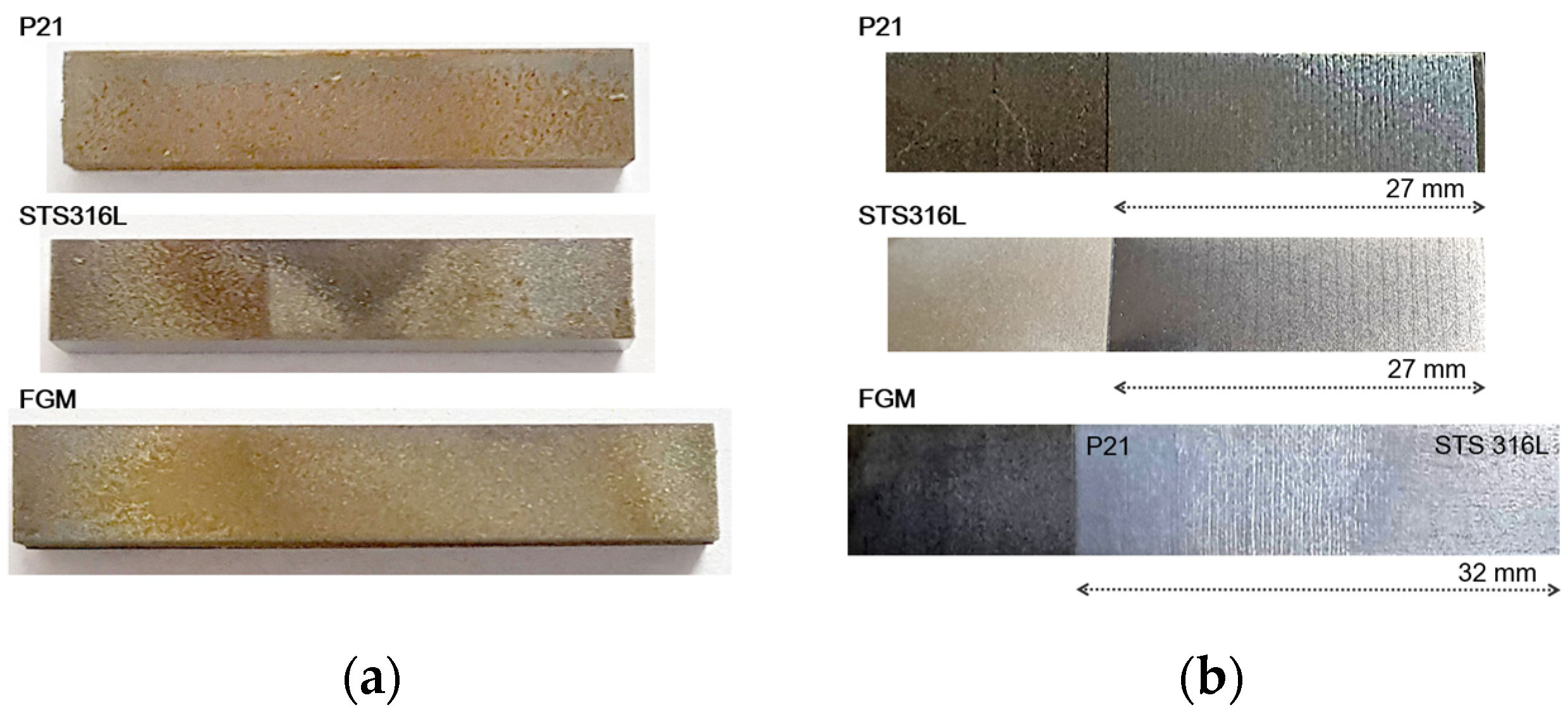
The microstructure observation cuboid blocks were made of P21, STS316L and FGM (P21-STS316L). The sizes of blocks were 27, 27, 32 mm, respectively, and the stacking direction is described in the Figure 2b schematic diagram. Single composition blocks were laminated in a high-purity argon atmosphere using a multi-hopper DED 3D printer (InssTek, MX-Lab). The blocks were laminated with 90 layers to a thickness of 0.3 mm. The FGM block was laminated with a thickness of 0.3 mm and 100 layers while changing the P21 and STS316L by 1% each. The 3D printing parameters are summarized in Table 2.
Blocks for tensile and impact tests were made of P21, STS316L, and FGM in 100 × 10 × 1 and 55 × 10 × 2.5 sizes, respectively, and plate tensile specimens (ASTM E8, Figure 3a) and 1/4 inch sub-size (ASTM E23, Figure 3b) impact specimens were manufactured.
Specimens for microstructure analysis were fabricated by wire cutting and hot mounting of laminated material, and Macro, optical microscope (OM), scanning electron microscope (SEM), energy-dispersive X-ray spectroscopy (EDS), electron probe X-ray micro analyzer (EPMA), X-ray diffraction (XRD) and electron backscatter diffraction (EBSD) analysis were performed. Macrostructures were measured with a DSLR digital camera (Nikon D80, Tokyo, Japan) for the blocks in the etching state of 5% Nital (P21) and Glyceregia (STS316L, FGM) after one micro polishing. Inclusions were measured at 200 magnification using OM (Leica DM 27000M, Wetzlar, Germany) in the micro polishing condition. OM (Leica DM 27000M, Wetzlar, Germany), SEM (Hitachi, S-4800, Tokyo, Japan), EDS (HORIBA, EMAX, Kyoto, Japan) analysis were performed. XRD (PANAlytical, X’Pert PRO MPD, Malvern, UK) measured the entire area of the P21, STS316L, and FGM blocks under the conditions of target Ceramic Cu, measuring angle 45 to 75°, 20 mA, and 45 kV and precipitation phase analysis was performed with HighScore Plus software. For EBSD analysis specimens, after polishing the FGM block by one micrometer, colloidal silica polishing was performed to remove surface residual stress with an automatic polisher (Presi, Mecatech, Eybens, France). EBSD (JEOL 7200F, Tyoko, Japan, Oxford, NanoAnalysis, Abingdon, UK) was measured with 20 kV of accelerating voltage, 70 μm step size. Band contrast, inverse pole figure (IPF), phase fraction and distribution analysis were performed using TSL orientation imaging microscopy software. EPMA (JEOL JXA8530F (5CH), Tyoko, Japan) component analysis was performed on micro-polished blocks.
Vickers hardness, tensile and instrumented impact tests were performed for physical property analysis. Vickers hardness (HMV-3T) was measured using microstructure analysis specimens. The measuring distance was 1 mm, the load was 9.8 N, and the holding time was 10 s. For the tensile test, P21, STS316L, and FGM plate tensile specimens were evaluated using the MTS model 45. For the impact tests, instrumented impact tests were performed using Zwick/Roell PSW750.

3. Results and Discussion

3.1. Macrostructure and Microstructure

Figure 4a shows the wire cutting surface of the DED laminate. Wire cutting was performed perpendicular to the direction of DED stacking. In all blocks, the wire cut surfaces exhibited red rust of the electrochemically oxidized surface due to the Electrical Discharge Machine (EDM). In the STS316L block (Figure 4a), a color difference was observed due to the difference in oxidation properties owing to material change at the interface between the substrate carbon steel and STS316L. Figure 4b shows the etched block surfaces after mirror polishing. Laser welding pass layers were clearly observed. Large-scale welding defects such as lack of fusion, porosity, cracks, and undissolved [24] were not observed in the macrostructure analysis.
Figure 5 shows micro defects in the polished blocks. Inclusions were observed, several micrometers in size, in all blocks. In STS316L, inclusions with a size of ten micrometers or more were observed, and the appearance frequency was the highest among the materials. During printing, surface oxides in the atomizing powder might be absorbed into the block during lamination and remain [25]. Inclusions were fine, individually dispersed, and were generally less likely to be considered harmful inclusions several millimeters in length [26]. Therefore, the DED stacked blocks structure was judged to be sound. P21 and STS316L were Fe-based materials with Fe content of 70% or more, and the powder shapes were similar to a 50–100 μm diameter sphere. Accordingly, the powder density, fluidity, laser absorption rate, dissolution and vaporization properties affecting the weld properties were similar in the three material blocks, and the blocks integrity was also ensured well [27].
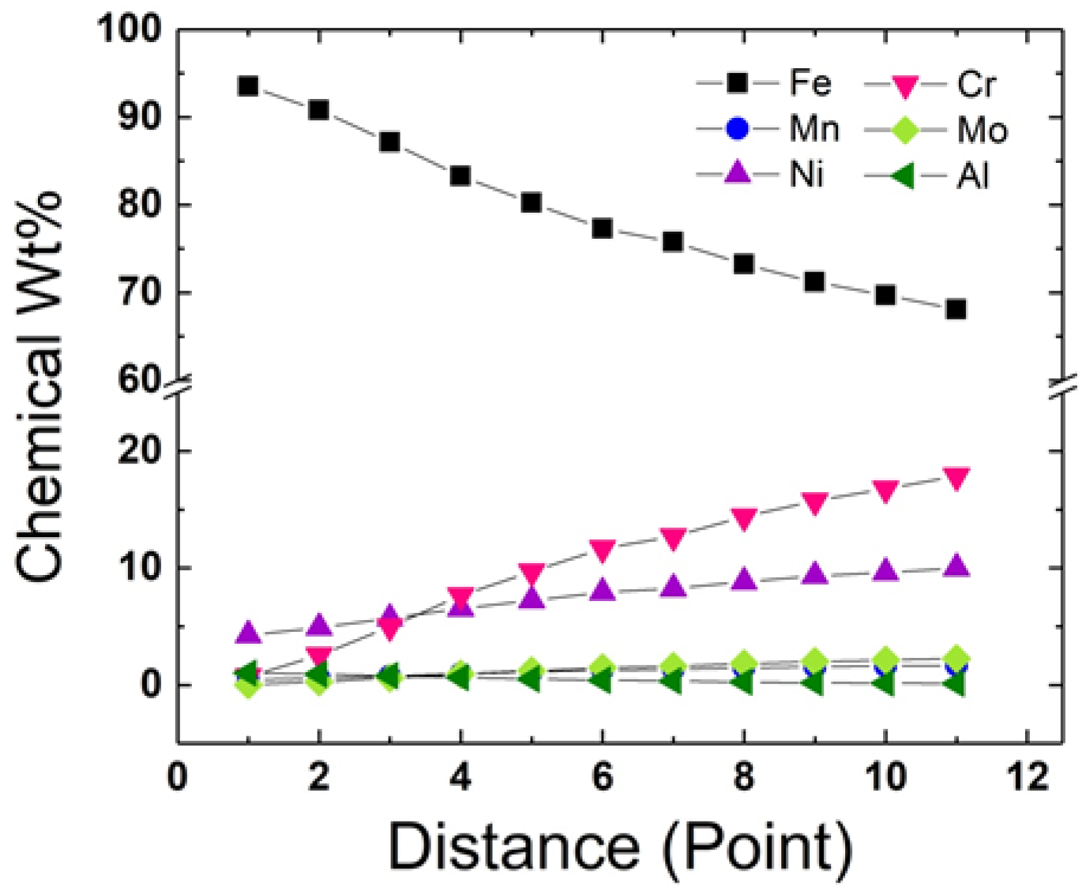
Figure 6 shows the content distribution measured through EDS of main components Fe, Cr, Ni, Mo, Mn, Al at 11 points at 1.5 mm intervals in the FGM block. The components changed almost linearly and continuously from P21 to STS316L and showed a distribution almost similar to the planned component distribution, so the block was well manufactured. A slight deviation of some components from the linear interpolation values of the two materials might be caused by volatilization and segregation during the melting and solidification process, or an injection amount error due to minute differences in properties between the two materials. The materials in this study were structural material, and the measured component differences were less than the allowable error range, so that would not cause considerable property differences. In the case of FEM lamination of materials that require sensitive properties, precise micro-composition control is necessary.
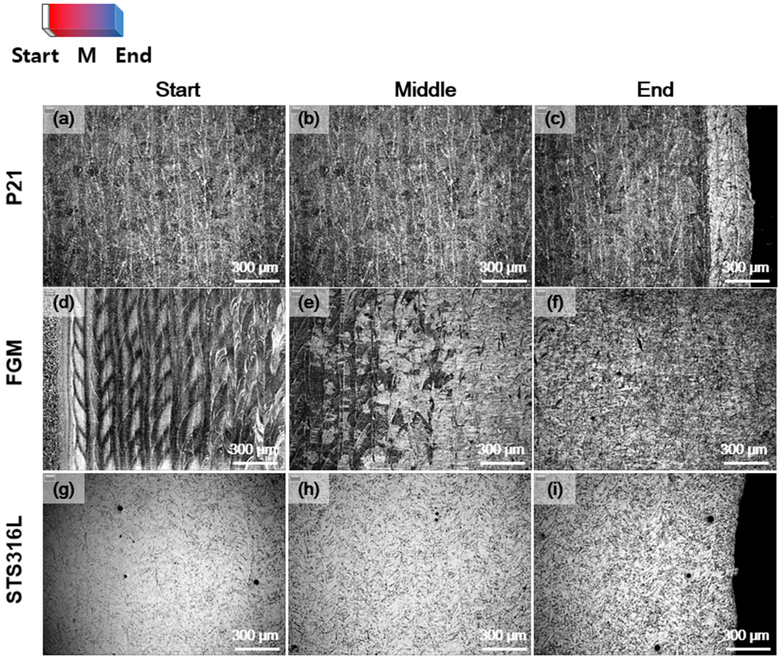
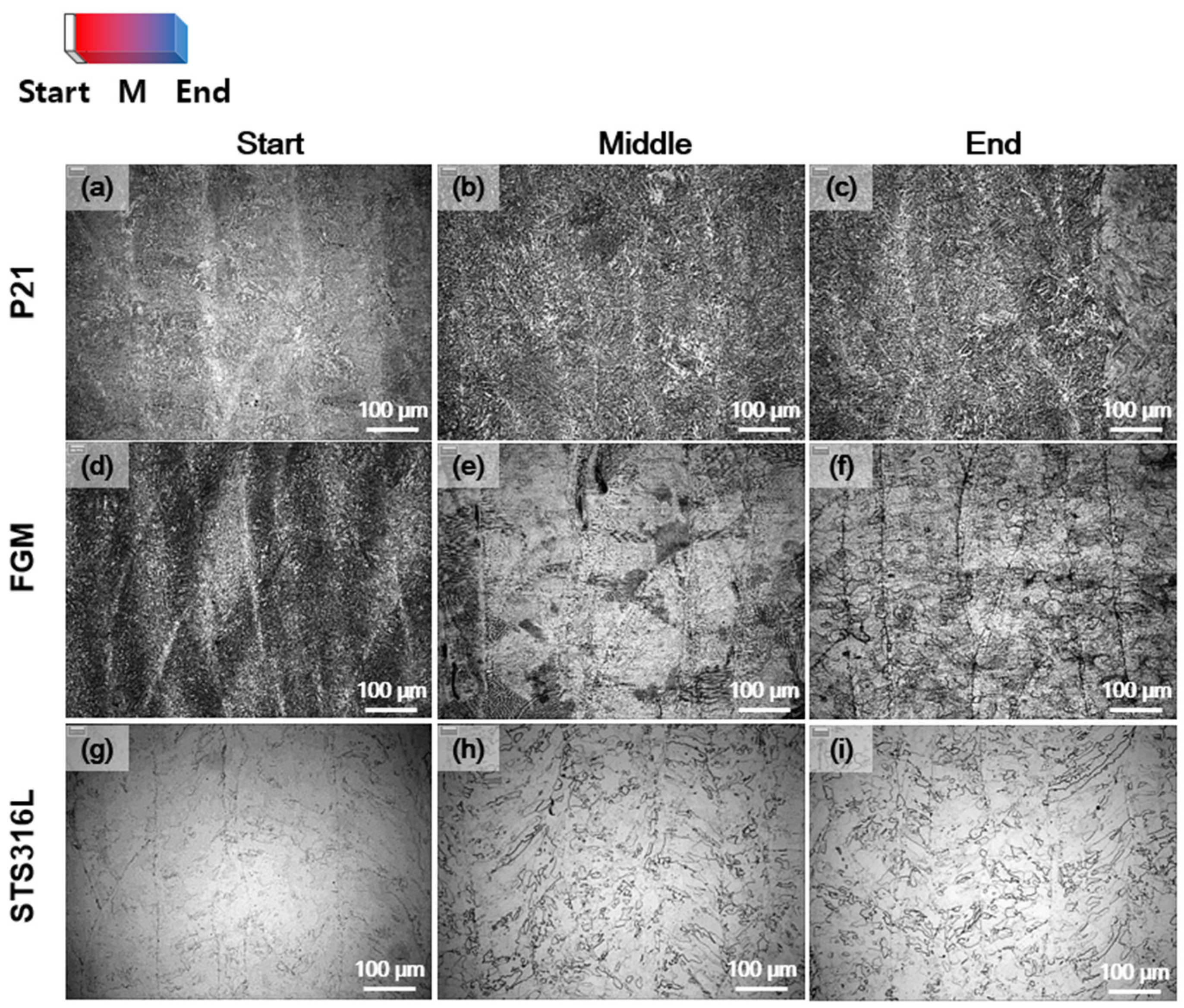
The shape of the DED laser welding beads according to the welding pass were observed in the OM image (Figure 7). Welding proceeded forward, backward, left and right on the laminated surface, and the welding paths were observed in sectoral shapes (vertical to the image) and band shapes (up and down horizontal to the image). In P21, white microstructures were observed along the surface of the weld bead, which were confirmed to be ferrite in the large magnification image (Figure 8). In continuous welding, austenizing due to reheating by the next pass welding on the weld bead surface and subsequent slow cooling was expected to form ferrite. In P21, the boundaries between the weld beads were clear and in STS316L that were faint. This was because in STS316L, there was no phase transformation even under reheat treatment by subsequent welding. In FGM, the microstructure was initially similar to P21, showed a specific microstructure in the mixed region, and gradually changed similar to final STS316L.
P21 showed the bainite structure in the 200× image (Figure 8a–c). At the beginning of the P21 block, microstructures with blurred phase boundaries were observed (Figure 8a). During multi-layer welding, the original structure could be degenerate by repeated reheating according to subsequent welding, and the phase boundary became blurred [28]. STS316L showed bimodal distribution grain composed of large grains with a diameter of near 50 micrometers and fine grains at the weld bead boundary. In the lamination area of the STS316L block, the grain size was large and the boundary between the beads was blurred. Particle size coarsening and component homogenization between weld beads occurred due to the heat treatment effect by subsequent welding. In the FGM block, the bainite microstructure observed at P21 was initially observed, and the same austenite structure as that of STS316L was observed at the end. In the middle of the FGM, distinct columnar dendrite structures not observed in other blocks were partially observed. The dendrites were observed in columnar shape and cell shape. Columnar dendrites grew during the solidification of the weld pool, and the dendrite shape was observed to be different from the columnar shape to the cell shape in the microstructure image according to the direction relationship between the cross section of the specimen and the dendrite column. Similar shapes and directions of dendrites were observed in the weld bead in the same direction because dendrite growth proceeded in the bead solidification direction and similar dendrites grew in the weld bead in the same direction. In the P21 and STS316L single material stacked blocks, dendrite was not observed because recrystallization occurred due to reheating during subsequent welding. Dendrite shapes were clearly observed in the FGM block. EBSD analysis confirmed the dendrites and the austenite structures surrounding them. The dual phase structure seems to have prevented homogenization due to subsequent heat treatment.
In the SEM image (Figure 9), as the mixing ratio with STS316L increased in the FGM region, the dendrite boundary became clear and the bainite region gradually decreased (Figure 9a,b). As the STS316L mixing rate further increased, again the dendrite boundaries faded (Figure 9c). At the weld bead interface, a mushy zone with a thickness of several micrometers was observed (Figure 9d). After the mushy zone, a number of fine dendrites were grown; the number gradually decreased, and the thickness increased to grow into columnar dendrites of a constant thickness. Porosity and shrinkage defects were observed at the weld bead boundary (Figure 9d). The inside of the dendrite was delta ferrite, and the strength was low due to component release during solidification. Dendrite external austenite had a high alloy content and could have higher strength than ferrite by solid solution strengthening. The deformation in the shrinkage appeared in the ferrite, and it seems to be due to the strength reversal phenomenon according to the alloy. With subsequent welding, the shrinkage was dissolved, but some remained. Shrinkage defects have a hollow tube shape and act as a crack initiation point during deformation, which can lead to a decrease in toughness.
In FGM, EBSD was measured at P21 volume fractions 100, 75, 50, 25, and 0%, and named as P100, P75, P50, P25, and P0, respectively. In the IPF, the prior austenite grain size was measured to be similar in bainite (P100, Figure 10a) and in austenite (P0, Figure 10e) as 40~50 micrometers. In the FGM dual phase region (P75, P50), structures of dendrite inner ferrite and outer austenite were observed. As columnar dendrites of ferrite structure were formed in the weld pool, the austenite stabilizing elements were discharged in the liquid phase and solidification was completed into the final austenite structure (Figure 10e). The austenite surrounding the dendrite effectively blocks dislocation movement, and the effective grains in the FGM state material cause a refining effect, which can lead to an increase in strength and hardness. Austenite showed a uniform distribution in P21-rich materials (P75, P50). In the STS316L-rich material (P25) ferrite distribution was biased in a prior austenite region.
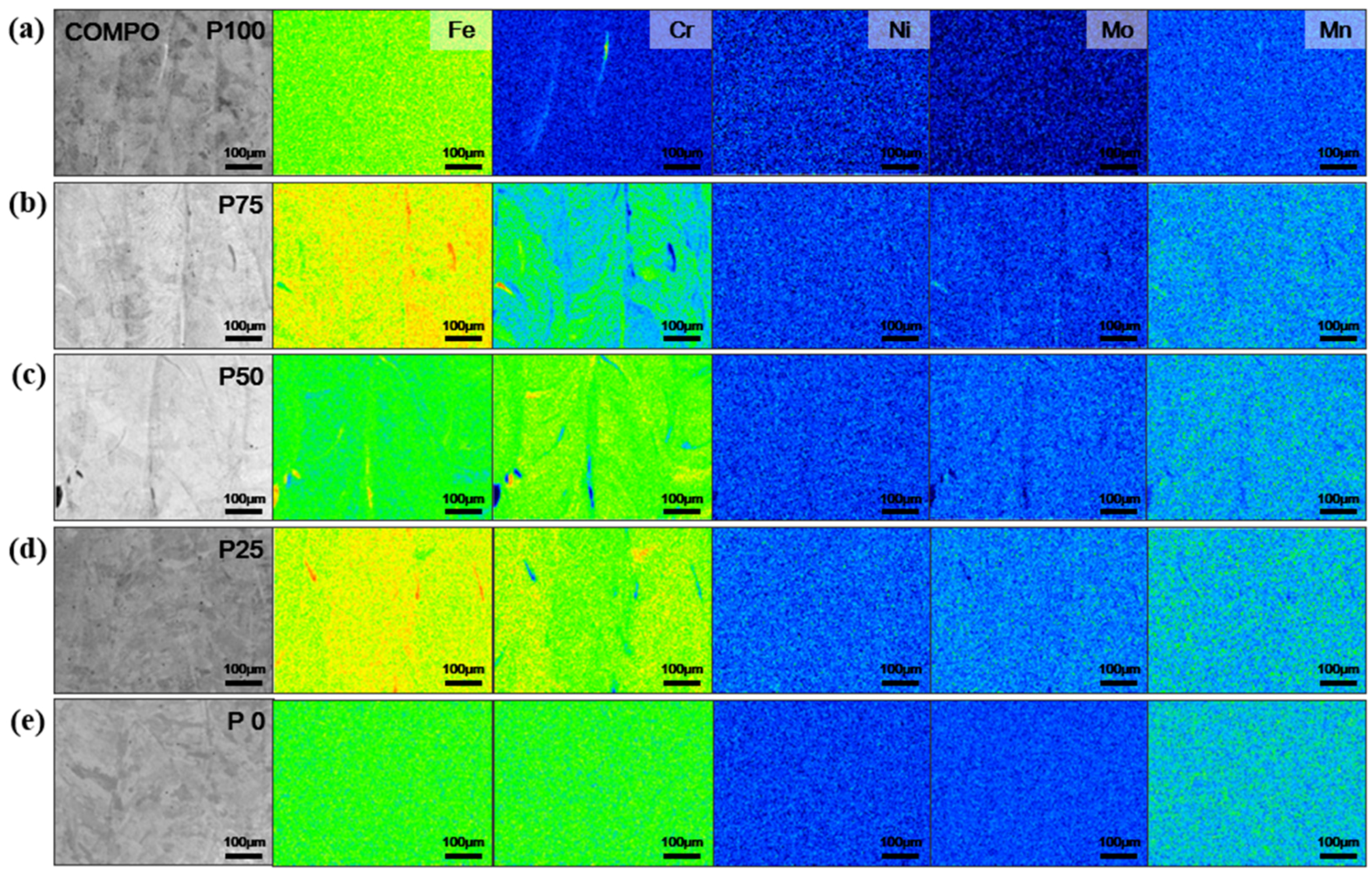
In EPMA analysis, chromium segregations were observed in P75, P50, and P25 materials (Figure 11). The amount of chromium alloy increased from 0.65 wt% in P21 to 17.01% in STS316L, and segregation occurred between phases and positions in FGM. Chromium segregation distribution was measured similar to the dendrite size on a few micrometers scale. The distribution of chromium biased on the austenite grain size scale at P25 was similar to the non-uniform distribution of ferrite at EBSD P25. Therefore, it was determined that the main element that induced the dual phase shape characteristic in FGM was chromium. Chromium is a ferrite stabilizing element that induces ferrite in materials with a high content. Nickel content was high from 4.03 wt% of P21 to 10.02 wt% of STS316L, but segregation did not appear in all parts of FGM. Nickel was an austenite stabilizing element, and it was gradually mixed with P21 in FGM leading to an increase in the austenite fraction. Segregation of elements such as nickel, molly, and manganese, which were the main alloying elements, was not found and was distributed evenly, and alloy formation during powder mixing and dissolution during laser welding appeared to be correct.

3.2. Precipitations

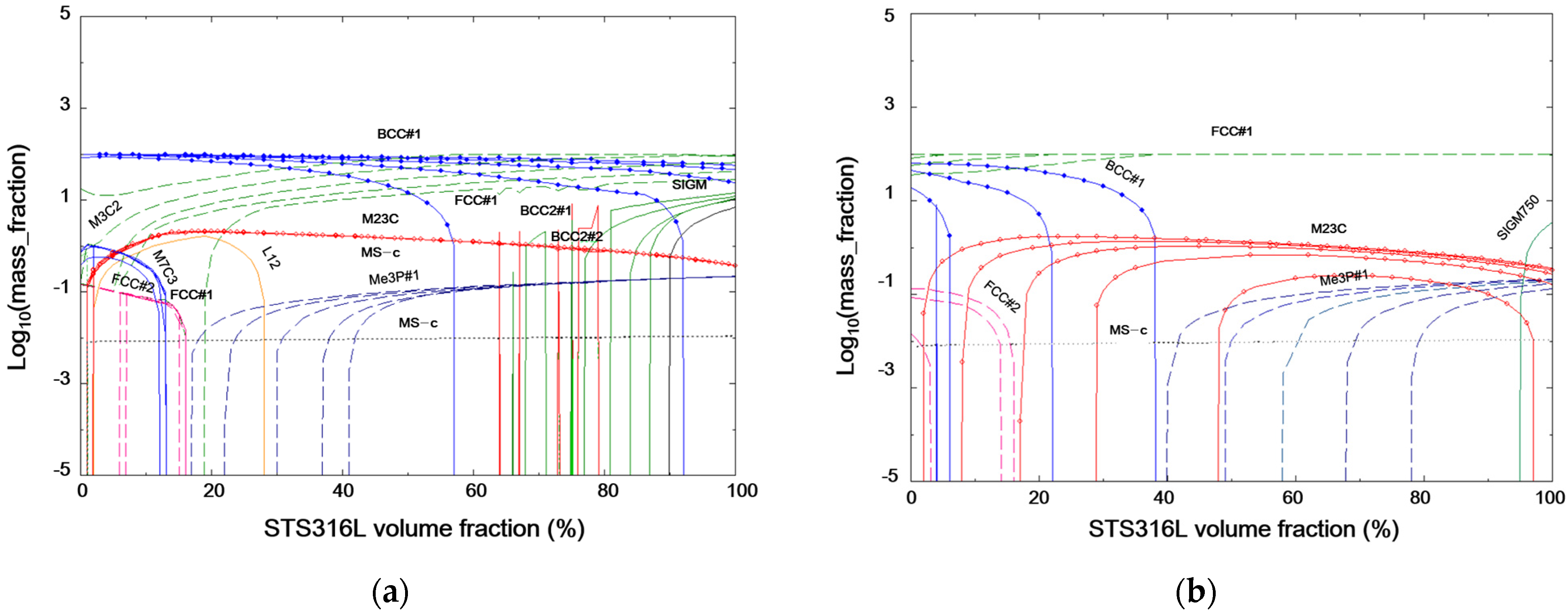
As a result of the equilibrium diagram thermodynamics software (CALPAD Factsage) analysis, the BCC fraction decreased and the FCC fraction increased as P21 was mixed with STS316L (Figure 12a). As the tempering heat treatment temperature increases, the FCC fraction increases (Figure 12b). The carbide-forming elements were Cr, Mo, and V. In P21, the total amount of the corresponding elements was 0.77 wt%, and in STS316L, it increased to 19.05 wt%. As for carbides, M23C6 was the main element in the region with high P21, but as the STS316L fraction increased, carbides with large alloys such as M3C5 and M7C3 increased. As STS316L increased, the carbon content decreased and the amount of precipitation phase forming elements, e.g., Chromium and Molybdenum, increased (Table 1). The L12 phase occurs from 2% of STS316L and appears to be (Ni, Mn)3AlC kappa carbides formed by combining aluminum and carbon in P21 with nickel and manganese in STS316L [29]. The L12 phase started to occur as the STS316L was mixed and was maintained up to 30% and disappeared. That was because the carbon and aluminum content decreased as the STS316L fraction increased. At 30% or more of STS316L, a section where the precipitated phase disappeared, the matrix structure was changed to FCC and the total amount of carbon decreased as most carbon became solid solution. STS316L over 65%, sigma phase was formed. Sigma phase is an intermetallic compound between Fe and Cr. It has a layered structure and is an element that occurs when the cooling rate is slow at high temperature in high chromium steel [30]. The layered structure is likely to act as a crack initiation point and lowers the impact toughness [31].
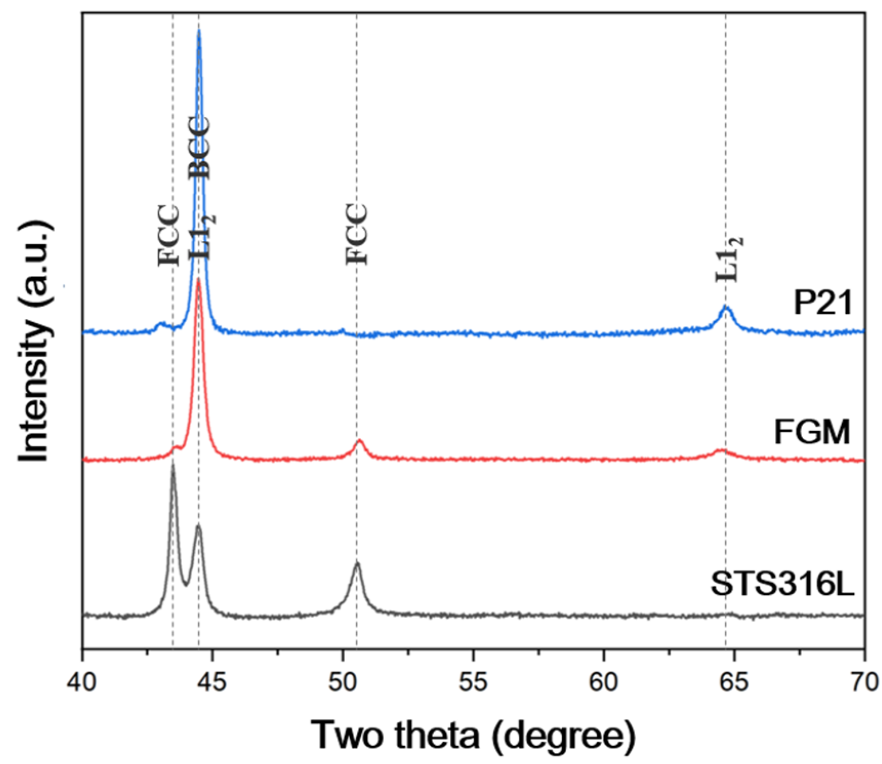
The precipitated phase analyzed by XRD was L12 (Figure 13). The frequency of confirmation of precipitation was low during SEM and XRD analysis of the material in this study. The precipitation phase predicted by thermodynamic calculations is an equilibrium phase that occurs when maintained at the temperature for a long time. On the other hand, the materials used in this study were laser welding materials, so solidification was very fast and the high temperature exposure time for forming the precipitated phase was short, so it was judged that there was a limitation in the formation of the precipitated phase. The precipitation phase observed in the material often had the shape of spherical inclusions, had a low frequency of appearance, and was located inside of grain. They appeared to have been incorporated during welding without dissolving after they were created during the production of the base material powder. Since the precipitation phase was hardly generated, the precipitation strengthening effect by heat treatment was judged to be small and the solid solution strengthening effect by the solid solution alloy element was strong.

3.3. Mechanical Properties

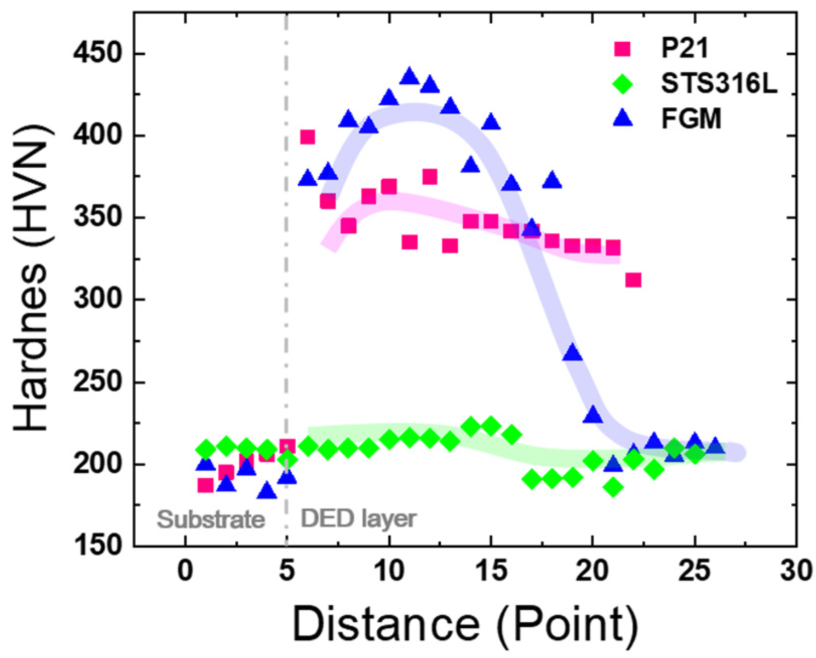
The hardness of FGM initially started at a level similar to that of P21, and as it was mixed with STS316L the hardness increased and then decreased and converged to the same hardness as STS316L (Figure 14). The hardness increase was measured up to 30% of STS316L (Figure 14), and this section was similar to the section where the L12 secondary phase was generated on the state diagram (Figure 12a). The increase in hardness in the initial section of FGM seems to be caused by solid solution strengthening, generation of L12 intermetallic compounds, and grain refinement due to dual phase distribution inside and outside the dendrite by mixing stainless steel in the P21 matrix. As the ratio of STS316L increased, the matrix changed to austenite and the carbon solubility of the matrix increased, resulting in a decrease in the amount of carbide causing precipitation hardening. As the amount of carbon in the base was reduced to the extremely low level of STS316L, solid solution strengthening by carbon, an interstitial element with a large solid solution strengthening effect, decreased. As the ferrite austenite dual phase disappeared, the effect of refining the particle size was reduced, and as a result it was interpreted that the hardness was lowered to the level of STS316L. The FGM hardness between P21 and STS316L was not numerically proportional to the ratio of the two materials but strengthening and softening occurred according to the microstructure phenomenon. An increase in hardness in the initial section of FGM increases dissimilar metal weld adhesion, but may accelerate SCC [32]. Therefore, it is not suitable to apply FGM to the situation where SCC occurs in ferritic steel and austenitic steel welds in nuclear power plants. In addition, high hardness increases fatigue due to thermal deformation, so FGM is not suitable for reducing thermal fatigue of dissimilar welds. In the P21, STS316L single material block, the hardness decreased as it went to the surface where the lamination was finished. As the stacked block size increased, the surface moved away from the base, which was the heat sink, and the cooling was delayed. As a result, the heating temperature of the material increased and the holding time became longer, which might have increased the effect of grain coarsening or tempering and decreased the hardness.
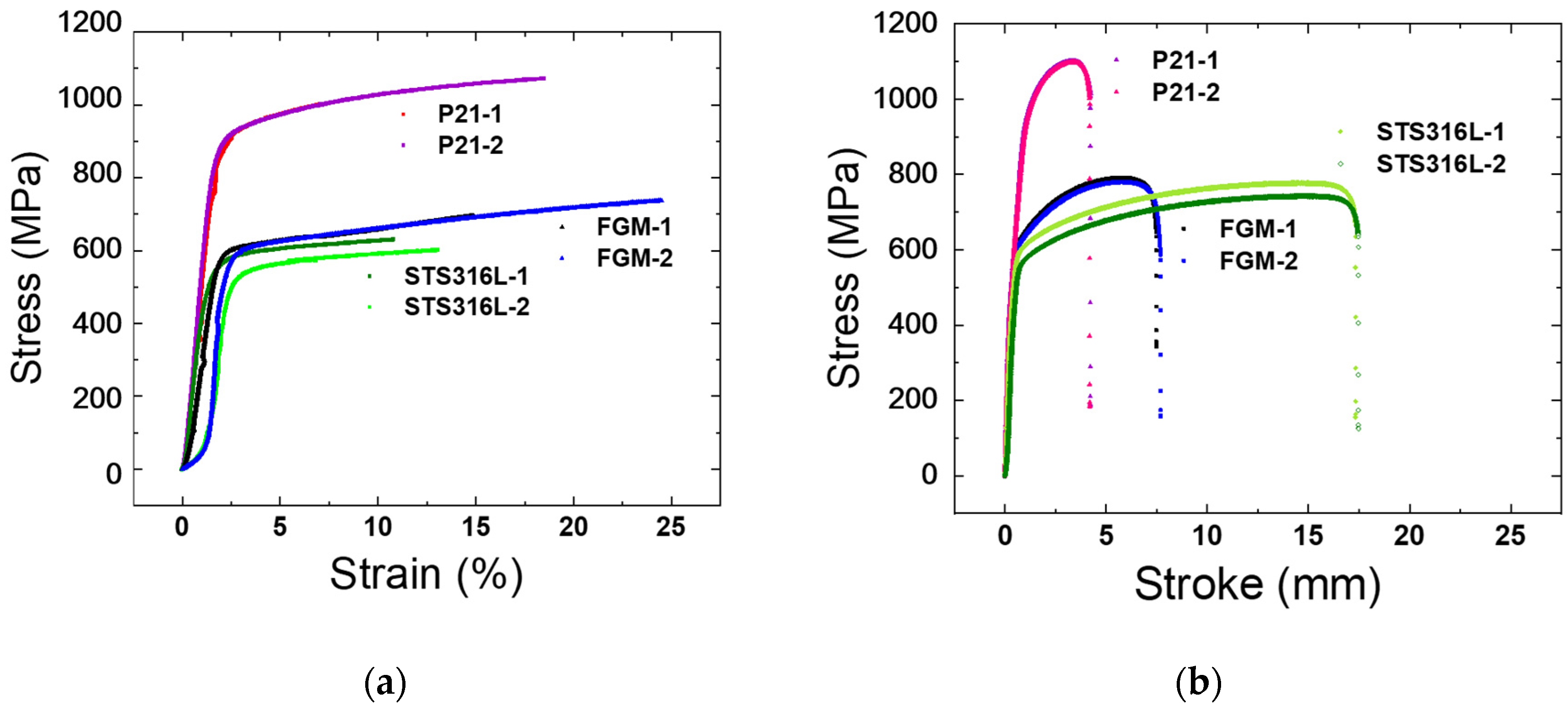
Tensile test results for P21, STS316L and FGM materials were compared (Figure 15). The ultimate tensile strength (UTS) of FGM material was 619 MPa, which was similar to that of STS316L at 616 MPa. The elongation of FGM was 20%, which was between 12% of P21 and 60% of STS316L. The strength of the weakest part would be measured in the tensile test of the FGM bulk material, which had different strength for each part in the material. Therefore, the yield strength and UTS seem to be measured by the properties of the unmixed STS316L material, which had the lowest yield strength and UTS among FGMs. As for the elongation, FGM showed intermediate values between P21 and STS316L. STS316L total strain length was reduced as the strain was confined to the STS316 region in FGM. U. Savita et al. confirmed that the tensile curve of the attached material coincided with the stainless steel tensile curve when the elongation was recalculated for only stainless steel in in625 and stainless steel joining materials [14].
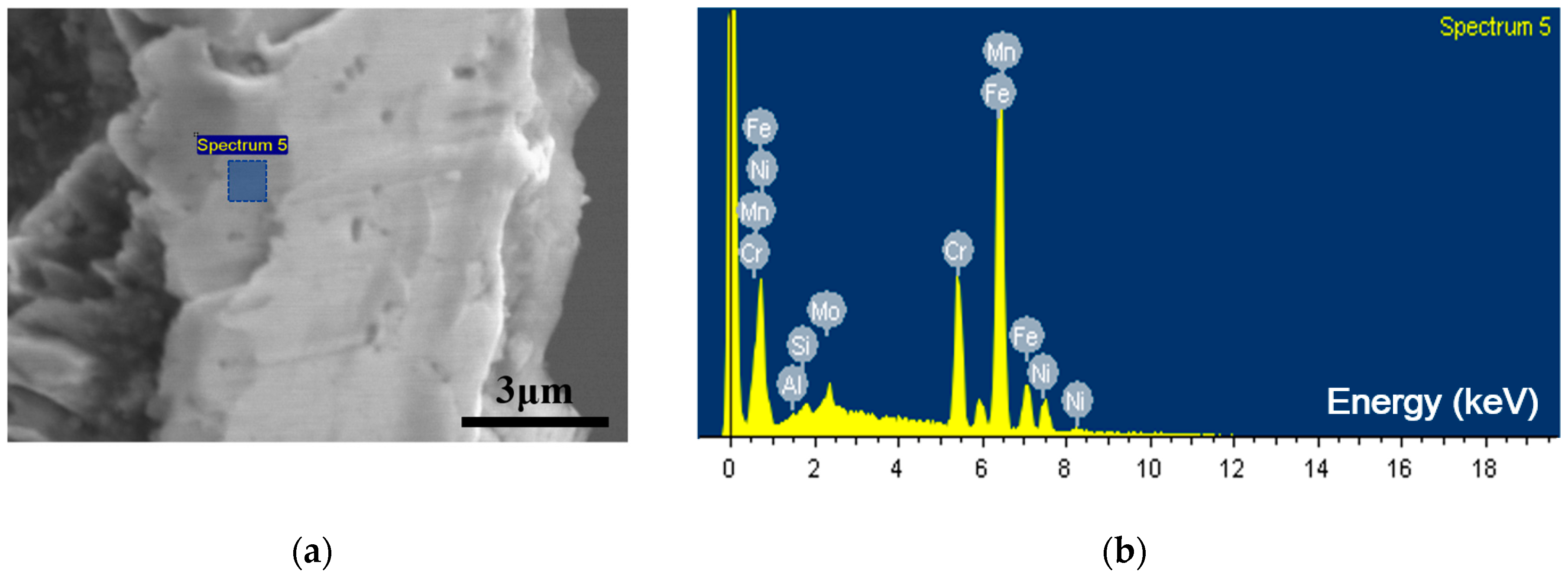
The fracture of tensile specimens of P21 material and STS316L material occurred near the center of the gage (Figure 16a,b). In the FGM material, the deformations were all biased to one side and the fracture occurred at the same location, 25% of the gage from the grip (Figure 16c). STS316L compositions were detected by EDS analysis of the fracture surface of the FGM tensile specimen (Figure 17, Table 3). In the FGM tensile specimen, fracture and deformation occurred only in the STS316L area outside of the FGM, so the FGM characteristics could not be identified from the FGM bulk material tensile test. Hardness tends to be proportional to yield strength [33]. Studies to predict tensile properties through instrumented indentation tests have been conducted [34]. In addition, studies on the strength evaluation of micro-specimens through the micro-pillar compression test have been conducted [35]. FGM strength and ductility studies can be conducted through indirect measurement of physical properties and conversion.
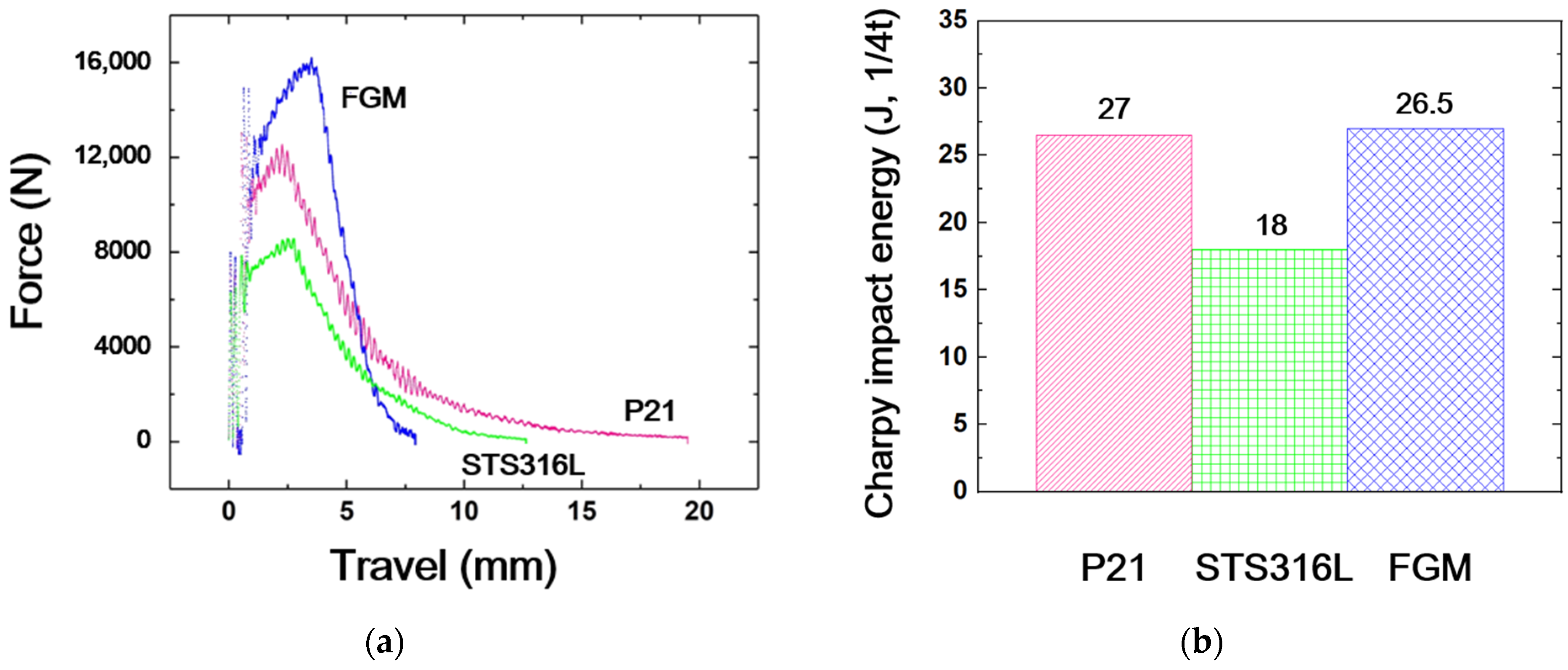
The 1/4T Charpy impact specimens were manufactured and instrumented impact tests were performed. P21, FGM, and STS316L showed high impact toughness in the order. In the graph of the instrumented impact test (Figure 18), the large absorbed energy is shown in the specimen with large force and travel distance. STS316L had low force and low total shock absorption energy. FGM had the highest force among the three materials, but had the shortest travel distance and showed a level of impact absorption energy similar to that of P21. In the impact test, the properties of the material of the notch region were measured. Therefore, in the FGM impact test, the characteristics of the P50 component material where the notch was located were measured. In FGM, specimens with changed notch positions can be manufactured and evaluated in order to secure impact characteristics according to the components of each part; however, there are restrictions on specimen production from small FGM blocks.

4. Conclusions

FGM blocks with continuously changing components over 0.3 mm and 100 layers from P21 to STS316L were successfully fabricated by a DED 3D printer, and the microstructure, component distribution and physical properties were evaluated. The stable matrix structure and precipitation phase were predicted by thermodynamic calculation, and the correlation with the microstructure and physical property changes could be confirmed. The important findings of this study are summarized below:
  • P21 and STS316L FGM blocks, whose components were precisely changed linearly depending on the part, could be manufactured with a multi-hopper metal DED 3D printer. P21 and STS316L are iron alloy spherical powders with similar density, fluidity, laser absorption rate, and dissolution properties. Therefore, FGM blocks with a sound microstructure at the level of a single material could be manufactured owing to smooth metal powder spraying, mixing and alloying;
  • In the DED 3D printing block P21 showed ferrite, STS316L showed austenite, and FGM showed ferrite, ferrite austenite duplex, and austenite microstructures, depending on the location. In P21 and STS316L, the dendrite structures disappeared due to the heat during welding; however, in the duplex area of FGM, the dendrites were maintained due to the interfaces between austenite phase in dendrite and ferrite phase inter dendrite. Precipitate phase was not observed in OM and SEM in FGM, and L12 phase was analyzed in XRD. L12 was one of the phases predicted by the Factsage thermodynamic calculations were not observed in the small magnification analysis, because the actual DED printing cooling rate was high and the alloy was supersaturated or the precipitate phases were finely formed;
  • In the FGM of P21 and STS316L, the hardness did not show an interpolation value between the properties of each material depending on the material mixing ratio; however, it increased to a larger value than P21 hardness, the strongest material among the two materials, and then decreased to the value of STS316L hardness. The hardness behavior was related to duplex phase fraction and distribution, precipitation strengthening, solid solution strengthening, and particle size refinement, according to the mixing of two materials with different components in FGM. High weld hardness improves bonding strength but reduces SCC and thermal fatigue properties. Therefore, setting a hardness target and forming an appropriate alloy is necessary to optimize the characteristics of the dissimilar metal welds;
  • FGM showed UTS of STS316L and intermediate elongation of STS316L and P21 single material. Impact toughness was measured at a level similar to that of P21. The strength of the weakest part of the FGM bulk tensile specimen was measured, and the impact toughness of the notched part of the impact specimen was measured. Since the material of FGM changes depending on the area, tensile and impact tests that measure only specific area characteristics are not suitable for FGM evaluation;
  • Alloy composition and physical properties change depending on location in FGM. Hardness can be measured by location of FGM, which is a suitable method for measuring FGM properties. Minimum scale alloy fabrication, evaluation, and analysis are possible with FGM fabrication, micro-hardness evaluation, OM, SEM, and XRD microstructure analysis. That can dramatically reduce time and cost of developing new alloys and securing material property database.
From this study, it is found that selection of welding materials based on physical property DB is necessary for improving FGM quality. In addition, it is confirmed that efficiency of new material production and physical property DB construction can be greatly improved by using DED 3D printing, FGM production, and microphysical property evaluation methods. FGM-based alloy development will be actively utilized as an efficient research method for development of materials that do not have existing physical property DB, such as high-entry alloys and extreme materials. In addition, the realization of shapes and components using the metal material property DB and DED 3D printing will contribute to the improvement of the industrial revolution manufacturing process that can highly personalize product manufacturing.

Author Contributions

Conceptualization, N.K. and D.N.; methodology, B.J.K. and S.G.L.; validation, Y.-s.A.; formal analysis, M.J.; investigation, H.-S.K.; writing—original draft preparation, M.J., B.K. and J.Y.P.; writing—review and editing, Y.-s.A., N.K., S.G.L., H.C.K. and D.N.; visualization, M.J. and H.-S.K.; supervision, B.K.; project administration, B.K.; funding acquisition, B.K. and D.N. All authors have read and agreed to the published version of the manuscript.

Funding

The materials: mechanical test and the APC of this study was supported by the Technology Innovation Program (20206500000020, Development of wear-resistant hard-facing materials and processes for NPP valve seat and disc) funded By the Ministry of Trade, Industry & Energy (MI, Republic of Korea) and the analysis (microstructure, precipitations, simulation) of this study was supported by the Global Flagship Industry Quality Response Root Technology Development Program (20016457, Development of 100 ton or more eccentric drive shaft manufacturing technology for ultra-large industrial machinery to enter the global market) funded By the Ministry of Trade, Industry & Energy (MI, Republic of Korea).

Data Availability Statement

The data presented in this study are available on request from the corresponding author.

Conflicts of Interest

The authors declare no conflict of interest.

References

  1. Carroll, B.E.; Otis, R.A.; Borgonia, J.P.; Suh, J.-O.; Dillon, R.P.; Shapiro, A.A.; Hofmann, D.C.; Liu, Z.-K.; Beese, A.M. Functionally graded material of 304L stainless steel and inconel 625 fabricated by directed energy deposition: Characterization and thermodynamic modeling. Acta Mater. 2016, 108, 46–54. [Google Scholar] [CrossRef] [Green Version]
  2. Saleh, B.; Jiang, J.; Fathi, R.; Al-hababi, T.; Xu, Q.; Wang, L.; Song, D.; Ma, A. 30 Years of functionally graded materials: An overview of manufacturing methods, Applications and Future Challenges. Compos. Part B Eng. 2020, 201, 108376. [Google Scholar] [CrossRef]
  3. Zhang, C.H.; Zhang, H.; Wu, C.L.; Zhang, S.; Sun, Z.L.; Dong, S.Y. Multi-layer functional graded stainless steel fabricated by laser melting deposition. Vacuum 2017, 141, 181–187. [Google Scholar] [CrossRef]
  4. Kim, S.; Chun, C.-K. Fe-Ni base Functionally Graded Deposition by Direct Energy Deposition Additive Manufacturing Process. J. Weld. Join. 2020, 38, 359–365. [Google Scholar] [CrossRef]
  5. Udupa, G.; Rao, S.S.; Gangadharan, K.V. Functionally Graded Composite Materials: An Overview. Procedia Mater. Sci. 2014, 5, 1291–1299. [Google Scholar] [CrossRef]
  6. Bobbio, L.D.; Otis, R.A.; Borgonia, J.P.; Dillon, R.P.; Shapiro, A.A.; Liu, Z.-K.; Beese, A.M. Additive manufacturing of a functionally graded material from Ti-6Al-4V to Invar: Experimental characterization and thermodynamic calculations. Acta Mater. 2017, 127, 133–142. [Google Scholar] [CrossRef]
  7. Shin, G.; Park, Y.; Kim, D.W.; Yoon, J.h.; Kim, J.H. Effect of Post-Weld Heat Treatment on Microstructure and Hardness Evolution of Functionally Graded Materials Produced by Direct Energy Deposition. Korean J. Met. Mater. 2021, 59, 81–98. [Google Scholar] [CrossRef]
  8. Jeong, J.-S.; Shin, K.-H. Fabrication of Functionally Graded Materials Between P21 Tool Steel and Cu by Using Laser-Aided Layered Manufacturing. Trans. Korean Soc. Mech. Eng. A 2013, 37, 61–66. [Google Scholar] [CrossRef]
  9. Nam, S.; Cho, H.; Kim, C.; Kim, Y.-M. Effect of Process Parameters on Deposition Properties of Functionally Graded STS 316/Fe Manufactured by Laser Direct Metal Deposition. Metals 2018, 8, 607. [Google Scholar] [CrossRef] [Green Version]
  10. Li, W.; Yan, L.; Chen, X.; Zhang, J.; Zhang, X.; Liou, F. Directed energy depositing a new Fe-Cr-Ni alloy with gradually changing composition with elemental powder mixes and particle size’ effect in fabrication process. J. Mater. Process. Technol. 2018, 255, 96–104. [Google Scholar] [CrossRef]
  11. Dev Singh, D.; Arjula, S.; Raji Reddy, A. Functionally Graded Materials Manufactured by Direct Energy Deposition: A review. Mater. Today Proc. 2021, 47, 2450–2456. [Google Scholar] [CrossRef]
  12. Yang, S.W.; Yoon, J.; Lee, H.; Shim, D.S. Defect of functionally graded material of inconel 718 and STS 316L fabricated by directed energy deposition and its effect on mechanical properties. J. Mater. Res. Technol. 2022, 17, 478–497. [Google Scholar] [CrossRef]
  13. Lin, X.; Yue, T.M.; Yang, H.; Huang, W. Laser rapid forming of SS316L/Rene88DT graded material. Mater. Sci. Eng. A 2005, 391, 325–336. [Google Scholar] [CrossRef]
  14. Savitha, U.; Jagan Reddy, G.; Venkataramana, A.; Sambasiva Rao, A.; Gokhale, A.A.; Sundararaman, M. Chemical analysis, structure and mechanical properties of discrete and compositionally graded SS316–IN625 dual materials. Mater. Sci. Eng. A 2015, 647, 344–352. [Google Scholar] [CrossRef]
  15. Niendorf, T.; Leuders, S.; Riemer, A.; Brenne, F.; Tröster, T.; Richard, H.A.; Schwarze, D. Functionally Graded Alloys Obtained by Additive Manufacturing. Adv. Eng. Mater. 2014, 16, 857–861. [Google Scholar] [CrossRef]
  16. Hofmann, D.C.; Roberts, S.; Otis, R.; Kolodziejska, J.; Dillon, R.P.; Suh, J.O.; Shapiro, A.A.; Liu, Z.K.; Borgonia, J.P. Developing gradient metal alloys through radial deposition additive manufacturing. Sci. Rep. 2014, 4, 5357. [Google Scholar] [CrossRef] [Green Version]
  17. Reichardt, A.; Dillon, R.P.; Borgonia, J.P.; Shapiro, A.A.; McEnerney, B.W.; Momose, T.; Hosemann, P. Development and characterization of Ti-6Al-4V to 304L stainless steel gradient components fabricated with laser deposition additive manufacturing. Mater. Des. 2016, 104, 404–413. [Google Scholar] [CrossRef]
  18. Ahn, S.-Y.; Kang, N. The Effects of δ-ferrite on Weldment of 9-12% Cr Steels. J. Korean Weld. Join. Soc. 2013, 31, 8–16. [Google Scholar] [CrossRef] [Green Version]
  19. Shin, G.; Yoon, J.h.; Kim, D.W.; Park, Y.; Kim, J.H. A Study on the Influence of Laser Power on the Microstructure and Mechanical Properties of Functionally Graded Materials Produced by Direct Energy Deposition. Korean J. Met. Mater. 2020, 58, 782–792. [Google Scholar] [CrossRef]
  20. Zuback, J.S.; Palmer, T.A.; DebRoy, T. Additive manufacturing of functionally graded transition joints between ferritic and austenitic alloys. J. Alloy. Compd. 2019, 770, 995–1003. [Google Scholar] [CrossRef]
  21. Shah, K.; Izhar Ul, H.; Shah, S.A.; Khan, F.U.; Khan, M.T.; Khan, S. Experimental study of direct laser deposition of Ti-6Al-4V and Inconel 718 by using pulsed parameters. Sci. World J. 2014, 2014, 841549. [Google Scholar] [CrossRef] [PubMed]
  22. Pulugurtha, S.R. Functionally Graded Ti6Al4V and Inconel 625 by Laser Metal Deposition; Missouri University of Science and Technology: Rolla, MO, USA, 2014. [Google Scholar]
  23. Kim, D.-K.; Woo, W.; Kim, E.-Y.; Choi, S.-H. Microstructure and mechanical characteristics of multi-layered materials composed of 316L stainless steel and ferritic steel produced by direct energy deposition. J. Alloy. Compd. 2019, 774, 896–907. [Google Scholar] [CrossRef]
  24. Stavridis, J.; Papacharalampopoulos, A.; Stavropoulos, P. Quality assessment in laser welding: A critical review. Int. J. Adv. Manuf. Technol. 2017, 94, 1825–1847. [Google Scholar] [CrossRef]
  25. Saboori, A.; Toushekhah, M.; Aversa, A.; Lai, M.; Lombardi, M.; Biamino, S.; Fino, P. Critical Features in the Microstructural Analysis of AISI 316L Produced By Metal Additive Manufacturing. Metallogr. Microstruct. Anal. 2020, 9, 92–96. [Google Scholar] [CrossRef] [Green Version]
  26. E45-18a; A. Standard Test Methods for Determining the Inclusion Content of Steel. ASME: New York, NY, USA, 2018.
  27. Hoadley, A.; Rappaz, M. A thermal model of laser cladding by powder injection. Metall. Trans. B 1992, 23, 631–642. [Google Scholar] [CrossRef]
  28. Evaluation of Mechanical Property for Welded Austenitic Stainless Steel 304 by Following Post Weld Heat Treatment. Korean J. Met. Mater. 2017, 55, 664–670. [CrossRef]
  29. Cheng, W.-C.; Cheng, C.-Y.; Hsu, C.-W.; Laughlin, D.E. Phase transformation of the L1 2 phase to kappa-carbide after spinodal decomposition and ordering in an Fe–C–Mn–Al austenitic steel. Mater. Sci. Eng. A 2015, 642, 128–135. [Google Scholar] [CrossRef]
  30. Hsieh, C.-C.; Wu, W. Overview of Intermetallic Sigma (σ) Phase Precipitation in Stainless Steels. ISRN Metall. 2012, 2012, 732471. [Google Scholar] [CrossRef]
  31. Liang, T.; Hu, X.Q.; Kang, X.H.; Li, D.Z. Effect of The Sigma Phase on the Mechanical Properties of a Cast Duplex Stainless Steel during the Ageing Treatment at 850 °C. Adv. Mater. Res. 2013, 684, 325–329. [Google Scholar]
  32. Gooch, T. Stress corrosion cracking of welded joints in high strength steels. Weld. J. 1974, 53, 287. [Google Scholar]
  33. Busby, J.T.; Hash, M.C.; Was, G.S. The relationship between hardness and yield stress in irradiated austenitic and ferritic steels. J. Nucl. Mater. 2005, 336, 267–278. [Google Scholar] [CrossRef]
  34. Kim, J.-Y.; Lee, K.-W.; Lee, J.-S.; Kwon, D. Determination of tensile properties by instrumented indentation technique: Representative stress and strain approach. Surf. Coat. Technol. 2006, 201, 4278–4283. [Google Scholar] [CrossRef]
  35. Hu, Y.; Guo, Q.; Zhao, L.; Li, Z.; Fan, G.; Li, Z.; Xiong, D.-B.; Su, Y.; Zhang, D. Correlating micro-pillar compression behavior with bulk mechanical properties: Nanolaminated graphene-Al composite as a case study. Scr. Mater. 2018, 146, 236–240. [Google Scholar] [CrossRef]
Figure 1. Spherical Powders used for 3D Printing deposition: (a) P21; (b) STS316L.
Metals 12 02086 g001
Figure 2. Schematic diagram of DED deposited samples: (a) composition gradient; (b) deposition direction.
Metals 12 02086 g002
Figure 3. DED 3D printing specimen design with FGM (shaded area): (a) plate tensile specimen; (b) 1/4 thickness sub size impact test specimen.
Metals 12 02086 g003
Figure 4. DED block macro images: (a) EDM wire cut blocks; (b) Mirror polished and etched blocks. 10mm thickness base plates were located on the left. Different colors appeared after etching due to differences in chemical compositions from DED stacked blocks.
Metals 12 02086 g004
Figure 5. Inclusion distribution in DED samples: (a) P21; (b) STS316L; (c) FGM.
Metals 12 02086 g005
Figure 6. Compositions distributions of FGM block according to location by EDS analysis.
Metals 12 02086 g006
Figure 7. 50x OM microstructure images of P21, FGM and STS316L DED samples: (a) P21 start; (b) P21 middle; (c) P21 end; (d) FGM start; (e) FGM middle; (f) FGM end; (g) STS316L start; (h) STS316L h; (i) STS316L end.
Metals 12 02086 g007
Figure 8. 200× OM microstructure images of P21, FGM and STS316L DED samples: (a) P21 start; (b) P21 middle; (c) P21 end; (d) FGM start; (e) FGM middle; (f) FGM end; (g) STS316L start; (h) STS316L h; (i) STS316L end.
Metals 12 02086 g008
Figure 9. FGM dendrite SEM microstructure images: (a) dendrite images began to reveal; (b) clear dendrites shown; (c) dendrite fading; (d) weld bead boundary mushy zone and dendrite internal crack initiation.
Metals 12 02086 g009
Figure 10. EPMA band contrast, IPF and phase map analysis by location and mixing ratio in FGM samples: (a) P21 100–STS316L 0%; (b) P21 75–STS316L 25%; (c) P21 50–STS316L 50%; (d) P21 25–STS316L 75%; (e) P21 0–STS316L 100%.
Metals 12 02086 g010
Figure 11. EPMA COMPO images and major components distributions by location and mixing ratio in FGM sample: (a) P21 100–STS316L 0%; (b) P21 75–STS316L 25%; (c) P21 50–STS316L 50%; (d) P21 25–STS316L 75%; (e) P21 0–STS316L 100%.
Metals 12 02086 g011
Figure 12. Thermodynamic equilibrium phase diagram depending on fraction between P21 and STS316L and temperature: (a) temperature range 500~700 °C; (b) temperature range 750~950 °C.
Metals 12 02086 g012
Figure 13. XRD intensity of P21, STS316L and FGM samples.
Metals 12 02086 g013
Figure 14. Micro-hardness measurement depending on location of P21, STS316L and FGM DED samples.
Metals 12 02086 g014
Figure 15. Tensile test curves of P21, STS316L and FGM: (a) stress–strain curves; (b) stress–stroke curves.
Metals 12 02086 g015
Figure 16. Fractured specimens after tensile tests: (a) P21; (b) STS316L; (c) FGM.
Metals 12 02086 g016
Figure 17. Shape and compositions of the fracture surface of FGM tensile specimen: (a) EDS analysis of shade area in fracture surface, shaded area; (b) EDS energy spectrum.
Metals 12 02086 g017
Figure 18. Instrumented Charpy impact tests results of 2.5 mm sub-size specimens of P21, STS316L and FGM: (a) force–travel curve; (b) Charpy impact energy.
Metals 12 02086 g018
Table 1. Chemical compositions (wt%) of the DED 3D printing powders used.
ElementCSiMnPSNiCrMoAlCuV
P210.210.380.38-0.0034.030.65-1.110.010.12
STS316L0.020.491.390.0330.00410.0217.012.03---
Table 2. DED 3D printing process parameters.
ParametersValue
Beam diameter0.4 mm
Power200 W
Depositions speed850 mm/min
Deposition thickness0.3 mm/layer
Deposition rate3 g/min
Deposition modeZigzag
Hatch angle90°
Gas flowHelium
Table 3. Compositions of the fracture surface of the FGM tensile test specimen and deposited powders (wt%).
ElementFracture SurfacePowder
STS316LP21
Al0.08-1.11
Si0.910.490.38
Cr17.4917.010.65
Mn1.011.390.38
Ni10.2110.024.03
Mo3.062.03-
Publisher’s Note: MDPI stays neutral with regard to jurisdictional claims in published maps and institutional affiliations.